Loading ...
Loading ...
Loading ...
An all-pole disconnect switch having a contact
separation of at least 3mm in all poles should be
connected to supply power wiring.
Wrong wire connections may cause malfunction of
some electric components. After fixing wire, ensure
that leads between connection to fixed point have
some space.
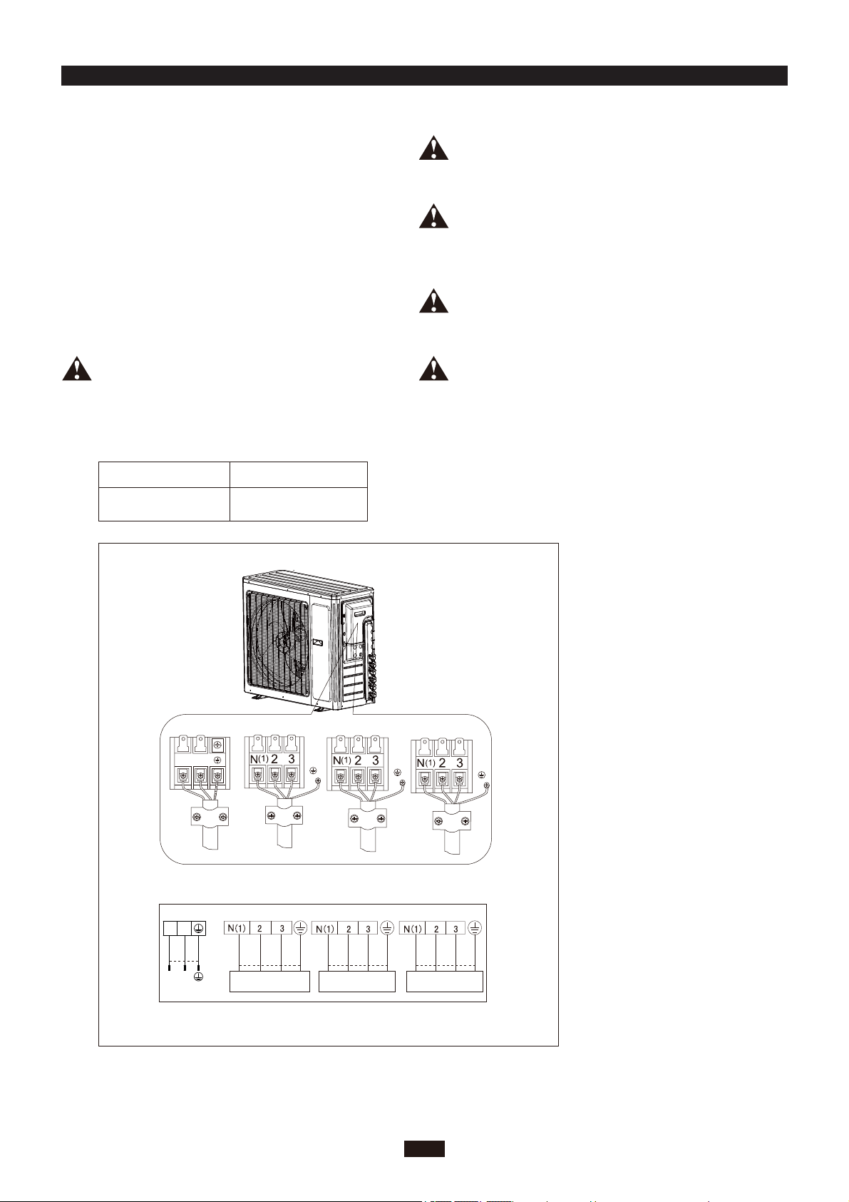
The connection pipes and the connection wiring of
unit A, unit B, unit C and unit D must correspond to
each other respectively.
The appliance shall be installed in accordance with
national wiring regulations.
1. Remove the handle at the right side plate of the
outdoor unit (one screw).
2. Remove the wire clamp, connect the power
connection wire to the appropriate terminal and
secure the connection. The wiring connections
must be consistent with the indoor unit terminal
connections. Wiring should match that of indoor
unit.
3. Secure power connection wire with a wire clamp.
4. Ensure all wire is securely attached.
5. Install the handle.
Note: The above figures are only intended to be a simple
diagram of the appliance and may not correspond to the
appearance of the units that have been purchased.
Provide a circuit breaker with suitable capacity,
please note the following table. Circuit
breakers will prevent short-circuits and
overload. (Caution: do not use a fuse only for
circuit protection.
40A
Breaker capacityAir-conditioner
MULTIU24HP230V1DO
MULTIU24HP230V1DO
ELECTRICAL CONNECTIONS INSTALLER
7
Power wire
L1 L2
To the power supply
To unit A
connecting
wire
To unit B
connecting
wire
To unit C
connecting
wire
INDOOR UNIT A INDOOR UNIT B
white
(blue)
white
(blue)
black
(brown)
red
(brown)
L2
L1
POWER
L1
L2
(yellow-
green)
green
(yellow-
green)
green
black white
(blue)
red
(brown)
(yellow-
green)
green
black
INDOOR UNIT C
white
(blue)
red
(brown)
(yellow-
green)
green
black
CBA
Loading ...
Loading ...
Loading ...