
Section 4 - ADJUSTMENTS & REPAIR
WARNING
DO NOT attempt any adjustments, maintenance,
service or repairs with the engine running. STOP
engine. STOP blade. Engage parking brake. Remove
key. Remove spark plug wire from spark plug and
secure away from plug. Engine and components are
HOT. Avoid serious burns, allow all parts to cool
before working on machine. Fuel Filler Cap and vent
must be closed securely to prevent fuel spillage.
4.2.4. MOWER DRIVE BELT ADJUSTMENT
(FOR 28" & 30" DECKS ONLY)
1. Remove mower drive belt cover. Refer to
Section "CHECK MOWER DRIVE BELT".
2. Move blade lever up and over to the "ON" position.
3. Place deck cutting height in the 3rd position.
Measure the belt spacing between idler pulley and
belt. The distance should measure 1-1/4" but no
less than 1". See Figure 4.5.
F 1-I/4"
y_-=
l ENGINE DRIVE
SPINDLE IDLER PULLEY
PULLEY PULLEY ASSEMBLY
FIGURE 4.5
4. If the distance is less than 1", adjust belt tension.
5. Move blade lever to the "OFF" position.
6. Loosen hardware that secures the clamp that
anchors the front frame assembly to the rear main
case. See Figure 4.6.
7. Pull front frame forward until belt spacing, with
blade lever "ON", measures 1-1/4".
8. Retighten hardware that secures clamp. Make sure
hardware is tightened securely.
IMPORTANT: The SNAPPER Rear Engine Rider Models
with 33" decks do not require belt tension adjustment. But, if
front frame assembly clamp is loosened for any reason,
recheck belt spacing between idler pulley and belt. With
blade lever in the "ON" position, the distance should
measure 1-3/4".
9. When belt adjustment is complete it will be
necessary to check Clutch/Brake Cable slack.
10. Disengage parking brake and allow pedal to remain
in the engaged wheel drive (Up) position. See Figure
4.7.
11. Clutch/Brake Cable should have approximately
3/16" of slack. If the cable does not have slack
adjustment of cable must be performed.
SLIDE FRONT
END ASSMBLY
LOOSEN
HARDWARE
LOOSEN HARDWARE AND SLIDE FRONT
FRAME ASSEMBLY FORWARD TO OBTAIN THE
DESIRED BELT TENSION MEASUREMENT
FIGURE 4.6
12. Peel back the rubber clutch/brake pedal pad and
push one ferrule through hole in pedal to attain slack
in cable. See Figure 4.7. Recheck cable for the
approximate 3/16" of slack. Replace pedal pad when
adjustment is complete.
IMPORTANT: Too much slack may cause improper
clutching and braking could be affected. Too little slack
may cause improper clutch function. Recheck service
brake/park brake and readjust if necessary. Refer to
Section "SERVICE BRAKE/PARK BRAKE ADJUSTMENT".
PEEL BACK PEDAL PAD. PUSH
ONEFERRULETHROUGH PEDAL.
RECHECK CABLE SLACK
FERRULE_
FERRULE
\
PEDAL IS SHOWN IN
THE ENGAGED OR UP
POSITION
js y
FIGURE 4.7
21
Section 4 - ADJUSTMENTS & REPAIR
WARNING
DO NOT attempt any adjustments, maintenance,
service or repairs with the engine running. STOP
engine. STOP blade. Engage parking brake. Remove
key. Remove spark plug wire from spark plug and
secure away from plug. Engine and components are
HOT. Avoid serious burns, allow all parts to cool
before working on machine. Fuel Filler Cap and vent
must be closed securely to prevent fuel spillage.
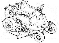
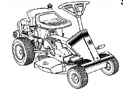
4.3 REAR ENGINE RIDER DRIVE COMPONENTS
Your Snapper rider is equipped with a patented
smooth start clutch. The clutch should operate
smoothly and provide ample traction. If problems are
experienced, contact your Snapper dealer for repair.
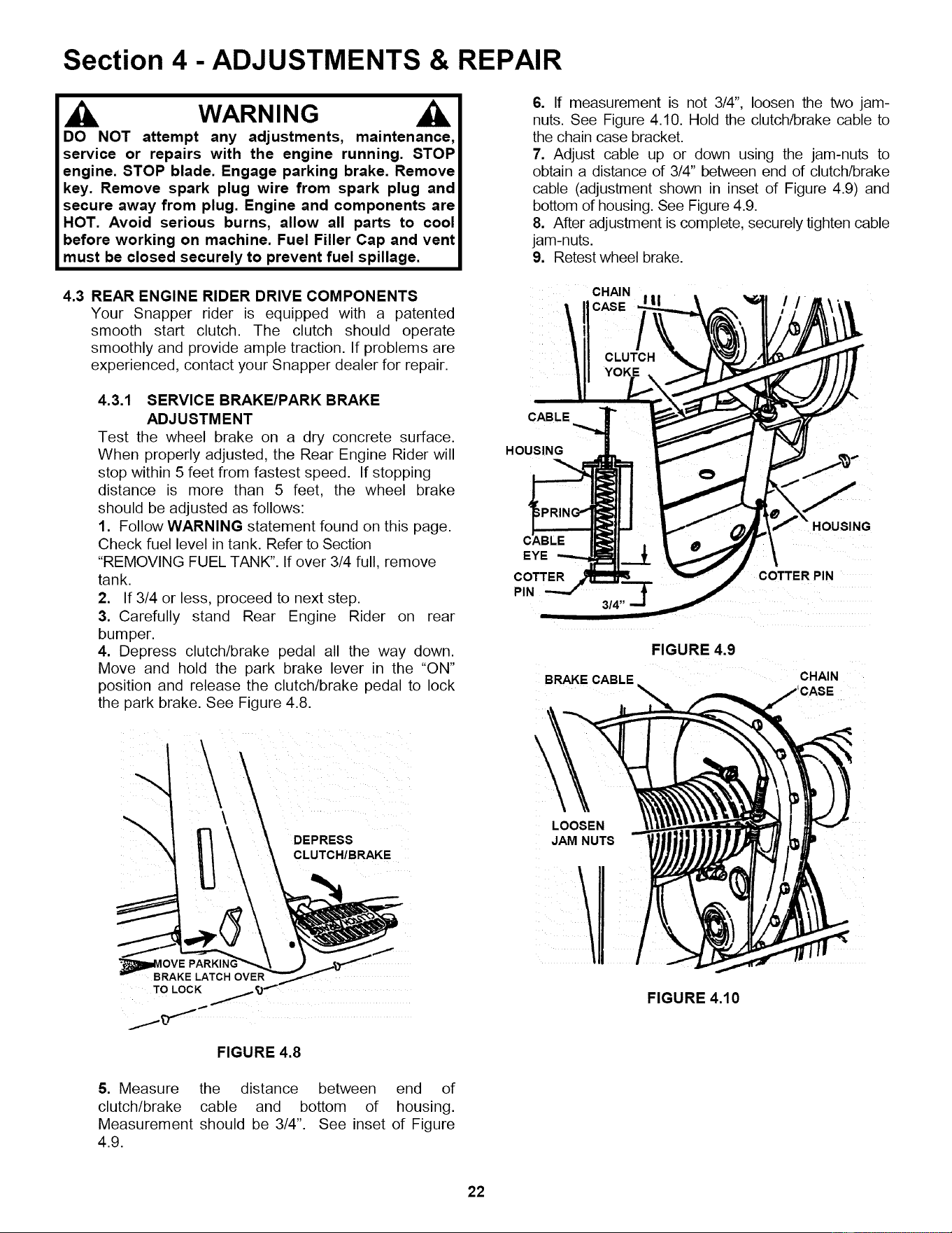
4.3.1 SERVICE BRAKE/PARK BRAKE
ADJUSTMENT
Test the wheel brake on a dry concrete surface.
When properly adjusted, the Rear Engine Rider will
stop within 5 feet from fastest speed. If stopping
distance is more than 5 feet, the wheel brake
should be adjusted as follows:
1. Follow WARNING statement found on this page.
Check fuel level in tank. Refer to Section
"REMOVING FUEL TANK". If over 3/4 full, remove
tank.
2. If 3/4 or less, proceed to next step.
3. Carefully stand Rear Engine Rider on rear
bumper.
4. Depress clutch/brake pedal all the way down.
Move and hold the park brake lever in the "ON"
position and release the clutch/brake pedal to lock
the park brake. See Figure 4.8.
DEPRESS
CLUTCH/BRAKE
OVE
BRAKE LATCH OVER
TO LOCK
FIGURE 4.8
6. If measurement is not 3/4", loosen the two jam-
nuts. See Figure 4.10. Hold the clutch/brake cable to
the chain case bracket.
7. Adjust cable up or down using the jam-nuts to
obtain a distance of 314"between end of clutch/brake
cable (adjustment shown in inset of Figure 4.9) and
bottom of housing. See Figure 4.9.
8. After adjustment is complete, securely tighten cable
jam-nuts.
9. Retest wheel brake.
CHAIN
CABLE
HOUSING
CABLE
EYE
COTTER
PIN
FIGURE 4.9
BRAKE CABLE
HOUSING
COTTER PIN
CHAIN
\
LOOSEN
JAM NUTS
/
FIGURE 4.10
5. Measure the distance between end of
clutch/brake cable and bottom of housing.
Measurement should be 314". See inset of Figure
4.9.
22
Section 4 - ADJUSTMENTS & REPAIR
WARNING
DO NOT attempt any adjustments, maintenance,
service or repairs with the engine running. Stop
engine. Stop blade. Engage parking brake. Remove
key. Remove spark plug wire from spark plug and
secure away from plug. Engine and components are
HOT. Avoid serious burns, allow all parts to cool
before working on machine. Fuel Filler Cap and Vent
must be closed securely to prevent fuel spillage. DO
NOT use a cutting blade that shows signs of
excessive wear or damage. On Rear Engine Riders
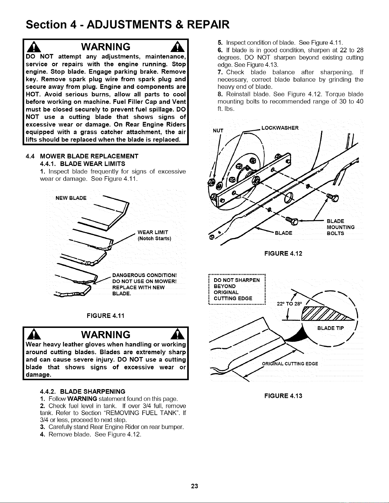
5. Inspect condition of blade. See Figure 4.11.
6. If blade is in good condition, sharpen at 22 to 28
degrees. DO NOT sharpen beyond existing cutting
edge. See Figure 4.13.
7. Check blade balance after sharpening. If
necessary, correct blade balance by grinding the
heavy end of blade.
8. Reinstall blade. See Figure 4.12. Torque blade
mounting bolts to recommended range of 30 to 40
ft. Ibs.
LOCKWASHER
equipped with a grass catcher attachment, the air
lifts should be replaced when the blade is replaced.
4.4
"°'d%/, / b
MOWER BLADE REPLACEMENT
4.4.1. BLADE WEAR LIMITS
1. Inspect blade frequently for signs of excessive
wear or damage. See Figure 4.11.
NEW BLADE
@
BLADE BOLTS
FIGURE 4.12
"_.= _ DANGEROUS CONDITION!
HARPEN
REPLACE WITH NEW
BLADE.
FIGURE 4.11
WARNING
Wear heavy leather gloves when handling or working
around cutting blades. Blades are extremely sharp
and can cause severe injury. DO NOT use a cutting
blade that shows signs of excessive wear or
damage.
CUTTING EDGE O/28o /_,,,_ -'-"
• .................................. ; 22 ° T X
BLADE TiP /
/
qAL CUTTING EDGE
4.4.2. BLADE SHARPENING
1. Follow WARNING statement found on this page.
2. Check fuel level in tank. If over 3/4 full, remove
tank. Refer to Section "REMOVING FUEL TANK". If
3/4 or less, proceed to next step.
3. Carefully stand Rear Engine Rider on rear bumper.
4. Remove blade. See Figure 4.12.
FIGURE 4.13
23

Section 4 - ADJUSTMENTS & REPAIR
WARNING
The electrolyte (acid) produces a highly explosive gas.
Keep all sparks, flame and fire away from area when
charging battery or when handling electrolyte or
battery. Electrolyte (acid) is a highly corrosive liquid.
Wear eye protection. Wash affected areas immediately
after having eye or skin contact with electrolyte (acid).
Battery acid is corrosive. Rinse empty acid containers
with water and mutilate before discarding. If acid is
spilled on battery, bench, or clothing, etc., Flush with
clear water and neutralize with baking soda. DO NOT
attempt to charge battery while installed on the RIDER.
DO NOT use "BOOST" chargers on the battery.
4.6.3. BATTERY SERVICE
1. Remove battery. Refer to Section "BATTERY
REMOVAL".
2. Place battery in a well ventilated area on a level
surface.
3. Using distilled water, refill cells as required to
cover cell plates of which can also be visualized
through the plastic battery case.
4. With cell caps removed, connect battery charger
to battery terminals. Red to positive (+) terminal
and black to negative (-) terminal.
5. Slow charge battery at 1 amp for 10 hours.
6. If battery will not accept charge or is partially
charged after 10 hours of charging at 1 amp,
replace with new battery.
4.6.4. BATTERY STORAGE
If mower is to be stored out of season on its rear
bumper, it is recommended the battery be removed,
charged and stored.
1. Remove battery. Refer to Section "BATTERY
REMOVAL".
2. Perform battery service.
3. Bring battery to full charge, if required.
4. Store battery in an area away from the RIDER on a
wood surface. DO NOT STORE BATTERY ON A
CONCRETE SURFACE.
4.6.5. NEW BATTERY PREPARATION
1. Remove battery from carton.
2. Place battery in a well ventilated area on a level
non-concrete surface.
3. Remove battery cell caps. Fill cells as required
with electrolyte (purchased separately) to proper
level. Fill to 3/16" above cell plates. Filling battery
with electrolyte will bring the battery to 80% charged
state.
4. With cell caps removed, connect battery charger to
battery terminals; RED to positive (+) and BLACK to
negative (-) terminal.
IMPORTANT: 3/16" above cell plates is the recommended
level. DO NOT place anything in battery other than specified
electrolyte.
lj , WARNING
DO NOT attempt to charge battery while installed on the I
Riding Mower. DO NOT use "BOOST" chargers on the
battery. DO NOT OVERFILL! I
5. Slow charge the battery at 1 amp for 2 hours to
bring the battery to full charge.
6. After charging, check level of electrolyte and add
as needed to bring level to 3/16" above cell plates.
7. Reinstall cell caps.
8. Remove the hair pin and swivel from the deck
support to allow clearance for battery installation.
9. Slide battery partially into battery housing.
10. Connect positive (+) cable (red) first, from wiring
harness to the positive terminal (+) on battery using
bolt and nut provided in hardware bag. Connect
negative (-) cable (black) last, to negative terminal (-)
on battery using bolt and nut. Apply a small amount of
grease over terminals to prevent corrosion.
11. Insert battery completely into battery housing.
12. Reinstall battery cover. See Figure4.17.
13. Reinstall swivel and hair pin for deck support.
4.6.6. BATTERY TESTING
There are two types of battery tests: Unloaded and
Loaded. The unloaded test is the procedure that will
be discussed. It's the simplest and most commonly
used. An unloaded test is made on a battery without
discharging current. To perform unloaded testing,
check charge condition using either a hydrometer or
voltmeter.
1. Using a voltmeter, voltage readings appear
instantly to show the state of charge. Remember to
hook the positive lead to the battery's positive
terminal, and the negative lead to the negative
terminal.
2. A hydrometer measures the specific gravity of
each cell. The specific gravity tells the degree of
charge; generally, a specific gravity of about 1.265
to 1.280 indicates full charge. A reading of 1.230 to
1.260 indicates the battery should be charged. The
chart on the next page shows the charge level as
measured by syringe float hydrometer, digital
voltmeter and five ball hydrometer.
Shield the positive terminal with terminal cover I
located on battery harness. This prevents metal from
touching the positive terminal, which could cause l
sparks. I
(Battery Testing Chart on Next Page)
26

PRIMARY MAINTENANCE
Generally, wash foam-type filters
In a dlshwashlng detergent and
water solution. Rinse and wring
dry, then saturate with oil and
squeeze out excess. Failure to
re-oil this type filter will ruin the
engine.
Clean paper elements by tapping
lightly. Blowing with air will
rupture paper elements.
Use a flashlight to detect clogged
or torn paper elements - replace If
damaged In any way.
Air Is also needed to keep
your engine cool. Dirt, dust
& debris build up to restrict
and clog cooling air Intake
screens and fins. Clean
screens and fins at frequent
Intervals. The engine blower
housing and shrouds should
be removed at least once
each season or more often
t under dry, dusty conditions
for a thorough cleaning of
fins.
Failure to keep external
surfaces clean not only
presents fire hazards, but
causes overheating and
resulting engine damages
such as:
1. distorted valve guides
2. sticking valves
t _°o. 3. scuffed, scored
,.,. walls
4. overspeedlng
5. loss of power
6. complete failure of
engine.
Dirt can also be introduced
into an engine In dirty fuel
from a contaminated
container. Always use clean
fresh fuel from a clean
container to guard against
dirt, sludge and water
contamination.
Be aware that fuel breaks
down in storage and forms
gummy compounds which
will block carburetor pass-
ages. Never use fuel more
than 3 months old. Drain
tank then run the engine out
of fuel before storing during
the off-season.
An engine must also have proper lubrication.
All engines use some oil. On 4-cycle engines,
CHECK OIL LEVEL BEFORE EACH START-UP.
Wipe area clean around the oll check plug or
dipstick opening to keep dirt from falling into
the engine when checking the oil. Always
check with the machine on a level surface.
On engines with dipstick, keep the level up to,
but not over, the FULL mark. When adding o11,
allow time for all of the oll to flow down the fill
tube to prevent a false full reading when the
level could actually be low and result In engine
damage.
35
PRIMARY MAINTENANCE
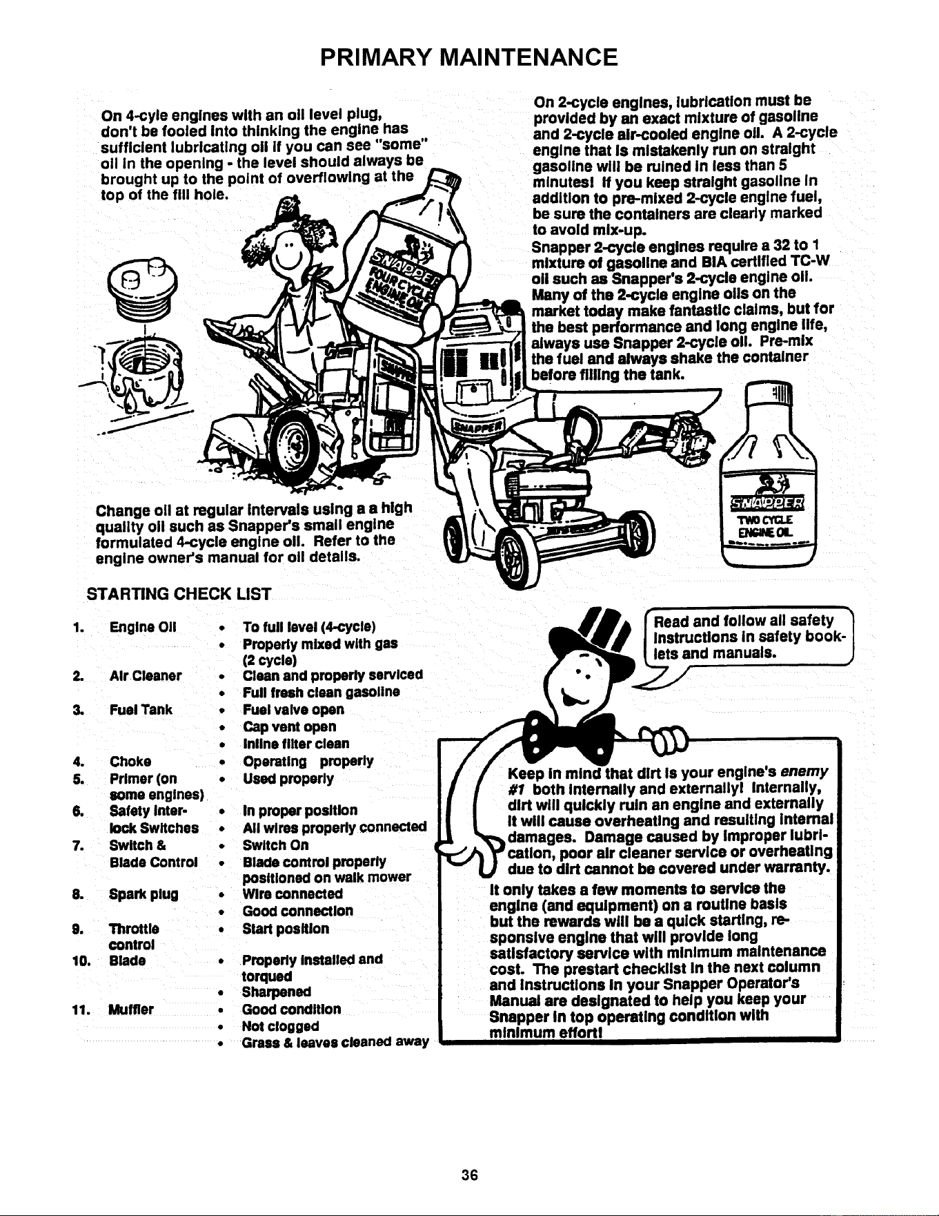
On 4-cyle engines with an oil level plug,
don't be fooled into thinking the engine has
sufficient lubricating oii if you can see "some"
oil in the opening - the level should always be
brought up to the point at the
top of the fill hole.
I
On 2-cycle engines, lubrication must be
provided by an exact mixture of gasoline
and 2-cycle air-cooled engine oil A 2-cycle
engine that Is mistakenly run on straight
gasoline will be ruined in less than 5
minutesl If you keep straight gasoline In
addlUon to pre-mixed 2-cycle engine fuel,
be sure the containers are clearly marked
to avoid mix-up.
Snapper 2-cycle engines require a 32 to 1
mixture of gasoline and BIA certified TC-W
oil such as Snapper's 2-cycle engine o11.
Many of the 2-cycle engine oils on the
market today make fantastic claims, but for
the best performance and long engine life,
always usa Snapper 2-cycle oil Pre-mix
the fuel and always shake the container
before tilting the tank.
Change oil at regular Intervals using a a high
quality oil such as Snapper's small engine
formulated 4-cycle engine oil Refer to the
engine owner's manual for oil details.
STARTING CHECK LIST
1. Engine Oil
2. Air Cleaner
3. Fuel Tank
4. Choke
5. Primer (on
someenglnes)
6. Safety Inter-
lock Switches
7. Switch &
BladeControl
8. Spark plug
9. Throttle
control
10. Blade
11. Muffler
• To full level (4-cycle)
• Properly mixed with gas
(2 cycle)
• Clean and properly serviced
• Full fresh clean gasoline
• Fuel valve open
• Cap vent open
• lnline filter clean
• Operating properly
• Used properly
• In proper position
• All wires propedy connected
• Switch On
• Blade control properly
positioned on walk mower
• Wire connected
• Good connection
• Start position
Properly Installed and
torqued
• Sharpened
• Good condition
• Not clogged
• Grass & leaves cleaned away
Read and follow all safety
Instructions in safety book-
lets and manuals.
Keep in mind that dirt Is your engine's enemy
#1 both Internally and externallyl Internally,
dirt will quickly ruin an engine and externally
It will cause overheating and resulting Internal
Damage caused by Improper lubrl-
poor air cleaner service or overheating
due to dirt cannot be covered under warranty.
It only takes a few moments to service the
engine (and equipment) on a routine basis
but the rewards will be a quick starting, re-
sponsive engine that will provide long
satisfactory service with minimum maintenance
cosL The prestart checklist In the next column
and Instructions In your Snapper Operator's
Manual are designated to help you keep your
Snapper In top operating condition with
minimum effortl
36

SNAPPER PRODUCT REGISTRATION FORM
IMPORTANT: KEEP THIS INFORMATION FOR YOUR PERSONAL RECORDS
(Complete the following information on your Snapper purchase)
Model Number
Serial Number
Date of Purchase
Retailer
Retailer's Phone Number
It is very important that you register your purchase with Snapper to ensure
warranty coverage. Please mail your product registration card to:
Snapper at P.O. Box 777, McDonough, Georgia 30253.
Or you may register on line at www.snapper.com.
You can contact us at our web site or if you would like to speak with a Customer
Service Representative. Call us at the Snapper Customer Relations Center. For
faster service please have your Serial Number and Model Number available.
Call the Snapper Customer Relations Center at 1-800-935-2967.
Eastern Standard Time
Monday through Friday from 8am to 6pm.
Saturday from 9am to lpm.
37

NOTES
38