
Ed:
Rev :
Cod :
INSTRUCTION
09/20 GRLDEVEEFK50000
- 2 -
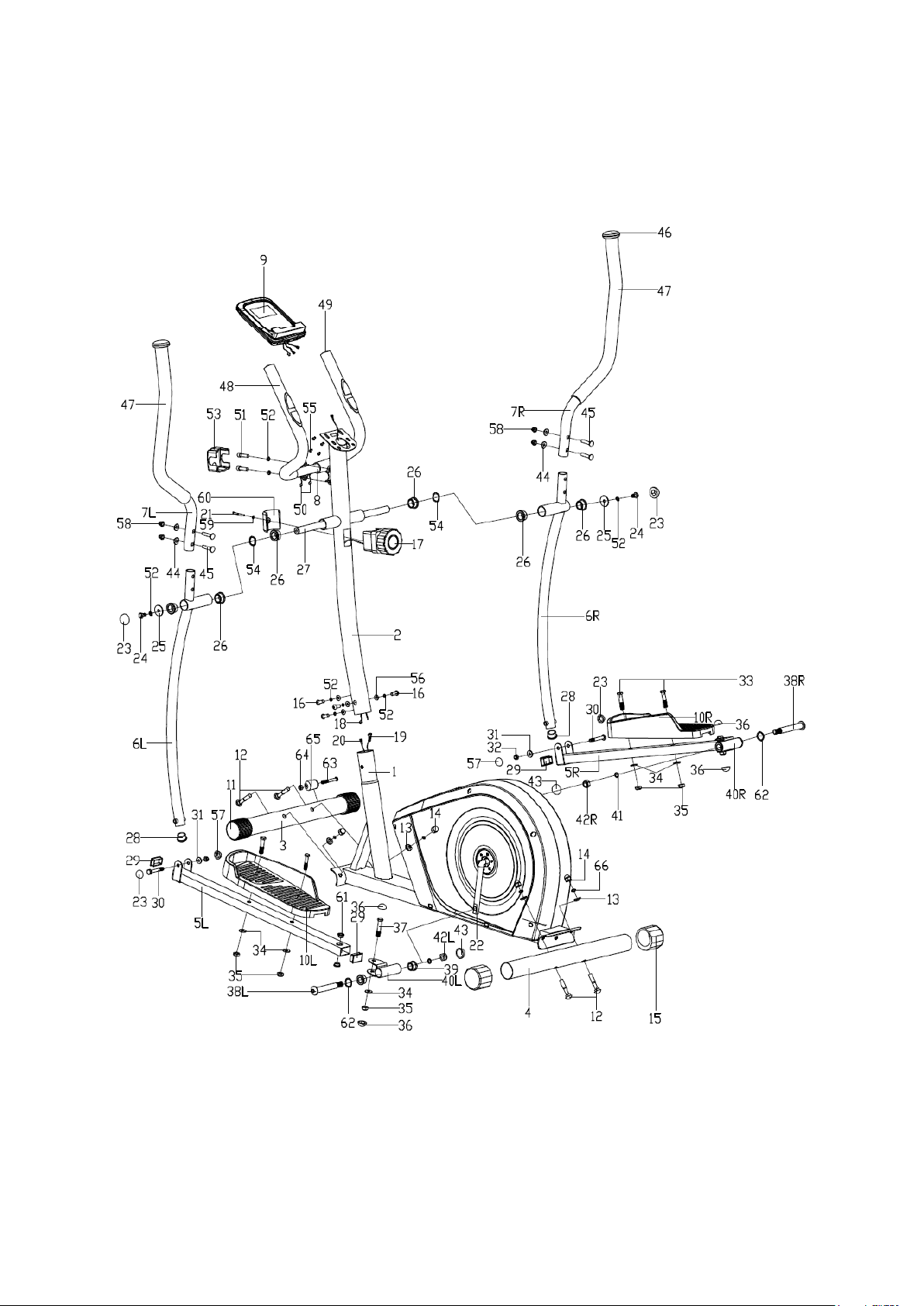
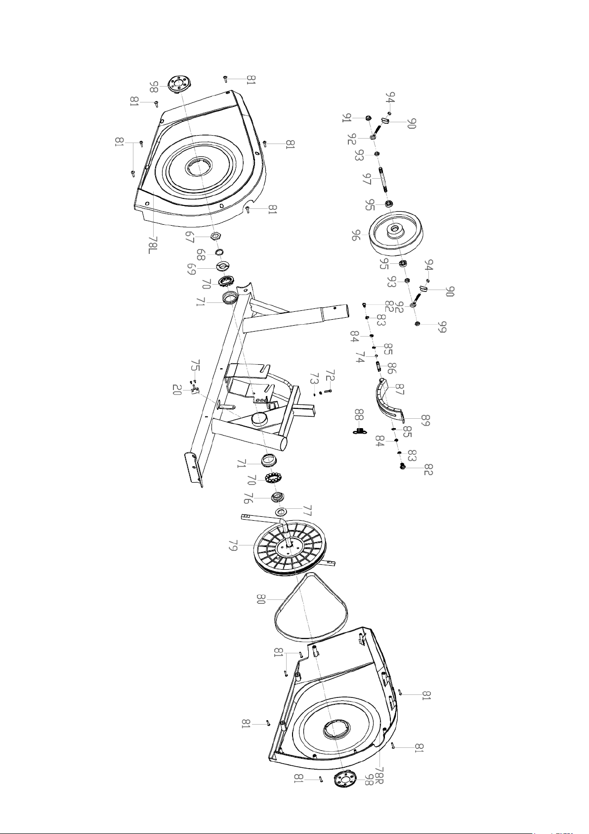
EXPLODED DIAGRAM
- 3 -

- 4 -
PARTS LIST
NO.
DESCRIPTION
QTY
NO.
DESCRIPTION
QTY
1
Main frame
1
51
Hex bolt M8X30
2
2
Handlebar post
1
52
Spring washer D8
8
3
Front stabilizer
1
53
Handlebar chuck cover
1
4
Rear stabilizer
1
54
Waved washer Φ20XΦ28 X0.3
2
5L/R
Pedal support (L/R)
1pr
55
Cross screw
4
6L/R
Swing bar(L/R)
1pr
56
Arc washer Φ20Xd8.5XR25
4
7L/R
Handlebar (L/R)
1pr
57
Nut cap S13
2
8
Armrest
1
58
Acorn nut M8
4
9
Computer
1
59
Flat washer D5
1
10L/R
Pedal (L/R)
1pr
60
Tension controller cover
1
11
Front end cap
2
61
Metal bushing Φ14X10XΦ10.1
4
12
Carriage bolt M10X63
4
62
Waveform washer D17X0.3
2
13
Arc washer Φ10 X1.5XΦ25XR28
4
63
Outer hexagon bolt M6XL45
2
14
Acorn nut M10
4
64
Nylon nut M6
2
15
Rear end cap
2
65
Transport wheel
2
16
Allen screw M8X15
4
66
Spring washer D10
4
17
Tension controller
1
67
Nut
1
18
Extension wire
1
68
Lock washer
1
19
Tension cable
1
69
Inside Bearing Collar
1
20
Sensor wire
1
70
Ball Bearing
2
21
Cross screw M5X45
1
71
Bearing Collar
2
22
Crank
1
72
Hex bolt M5 x 50
1
23
Nut cap S14
4
73
Hex nut M5
2
24
Hex bolt M8X15
2
74
Wave washer D12
1
25
Flat washer Φ8.2XΦ32 X2
2
75
Screw ST2.9 x 12
2
26
Axle bushing Φ32 X2.5
6
76
Outside Bearing Collar
1
27
Long axle
1
77
Big washer
1
28
Round end cap Φ28 X1.5
2
78L/R
Chain cover
1pr
29
Square end cap 40X25X1.5
4
79
Belt pulley
1
30
Hex bolt M8X55
2
80
Belt
1
31
Flat washer d8 X1.5
2
81
Screw ST4.2 x18
12
32
Nylon nut M8
2
82
Hex bolt M6 x 15
2
33
Hex bolt M10X45
4
83
Spring washer D6
2
34
Flat washer d10X1.5
6
84
Spring washer D6
2
35
Nylon nut M10
6
85
Circlip
2
36
Nut cap S16
4
86
Magnet board
1
37
Hex bolt M10X50
2
87
Magnet
8
38L/R
Pedal locking bolt (L/R)
1pr
88
Spring
1
39
Axle bushing Φ24 X20XΦ16.1
4
89
Magnet board
1
40L/R
Connecting joint (L/R)
1pr
90
U-shape washer
2
41
Spring washer Φ13 XB2
2
91
Flange nut M10 x 1
1
42L/R
Nylon nut (L/R)
1pr
92
Adjustable bolt
2
43
Nut cap S19
2
93
Hex conical surface nut M10x1
2
44
Arc washer Φ20 Xd8X2XR16
4
94
Hex nut M6
2
45
Carriage bolt M8X40
4
95
Bearing 6000
2
46
Mushroom end cap
2
96
Flywheel
1
- 5 -
47
Handlebar foam grip
2
97
Flywheel axle
1
48
Armrest foam grip
2
98
Crank cover
2
49
Round end cap Φ25X1.5
2
99
Hex thin nut M10 x 1
1
50
Pulse sensor wire
2
NOTE:
Most of the listed assembly hardware has been packaged separately, but some
hardware items have been preinstalled in the identified assembly parts. In these
instances, simply remove and reinstall the hardware as assembly is required.
Please reference the individual assembly steps and make note of all preinstalled
hardware.
PREPARATION: Before assembling, make sure that you will have enough
space around the item; Use the present tooling for assembling; Before
assembling please check whether all needed parts are available.
It is strongly recommended this machine to be assembled by two or more
people to avoid possible injury.
ASSEMBLY INSTRUCTION
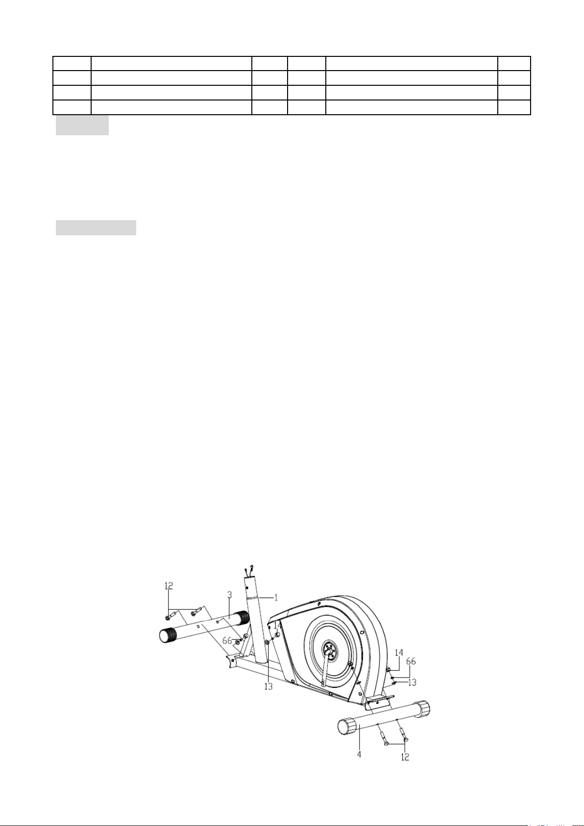
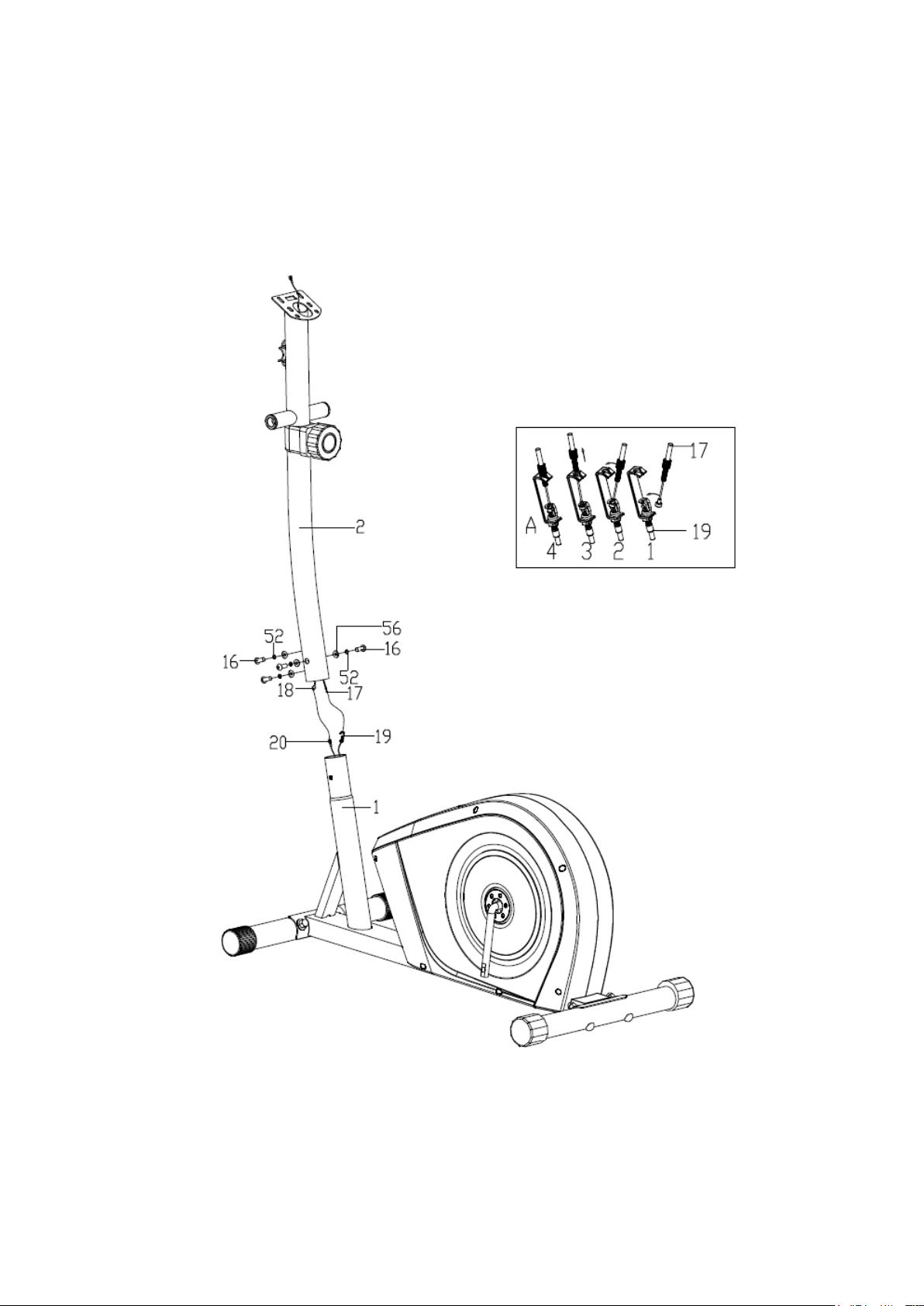
Step 1:
Fix the Front stabilizer (3) and Rear stabilizer (4) to the Main frame (1) with Carriage bolt
(12), Spring washer (66), Arc washer (13) and Acorn nut (14)
- 6 -
Connect the Sensor wire (20) well with Extension wire (18) and then connect the Tension
cable (19) well with wire of Tension controller (17) as shown.
Fix the Handlebar post (2) to the Main frame (1) with Allen screw (16), Spring washer (52),
Arc washer (56).
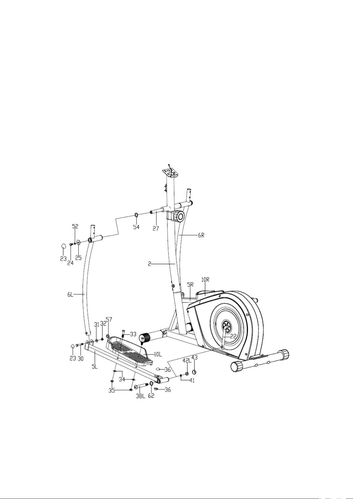
Step 2:
- 7 -
A: Fix the Swing bar (6L) on the long axle of the Handlebar post (2) with Hex bolt (24),
Spring washer (52), Flat washer (25), Waved washer (64) and Long axle (27) as shown.
Please do not tighten them this time.
B: Attach the connecting joint together with Pedal Support (5L) to the Crank (22) using
Pedal support bolt (38L), Waveform washer (62), Spring washer (41) and Nylon nut
(42L) as shown. Please do not tighten them this time.
C: Connect Swing bar (6L) with Pedal support (5L) using Hex bolt (30), Flat washer (31)
and Nylon nut (32). Tighten the Hex bolt (24) (30) and Nylon nut (42L). Finally Cover
the Nut caps (23) (57) (43)(36).
D: Fix the Pedal support (5R) and Swing bar (6R) to Crank (22) and Handlebar post (2) in
the same way.
E: Fix the Pedal (10L/R) to the Pedal support (5L/R) with Hex bolt (33), Flat washer (34)
and Nylon nut (35).
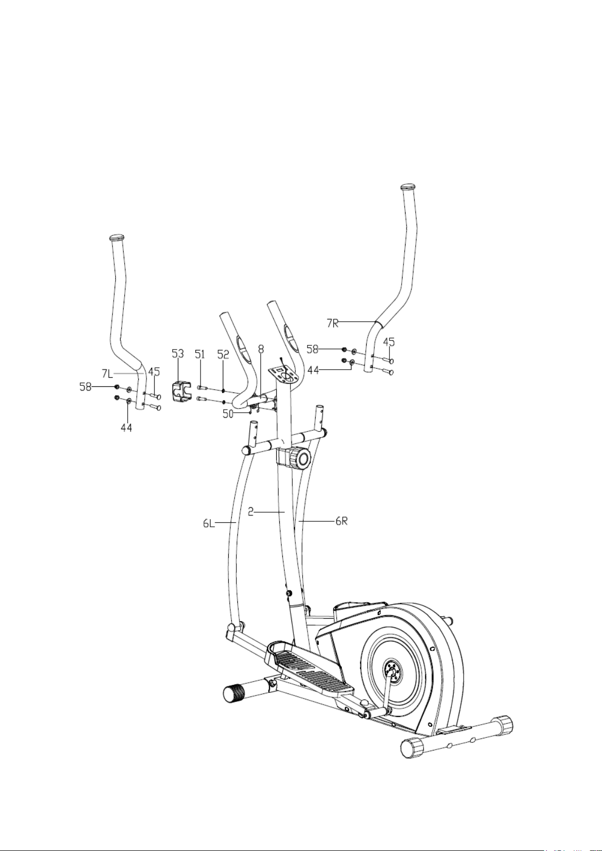
Step 3:
- 8 -
A: Put the Pulse sensor wire (50) through the handlebar post (2) and then out of the hole
of the computer bracket. Fix the armrest (8) on the handlebar post (2) with Hex screw
(51), Spring washer (52) and then cover the Handlebar chuck cover (53) to the related
position.
B: Attach the Handlebar (7L/R) to the Swing bar (6L/R) using Carriage bolt (45), Arc
washer (44) and Acorn nut (58).
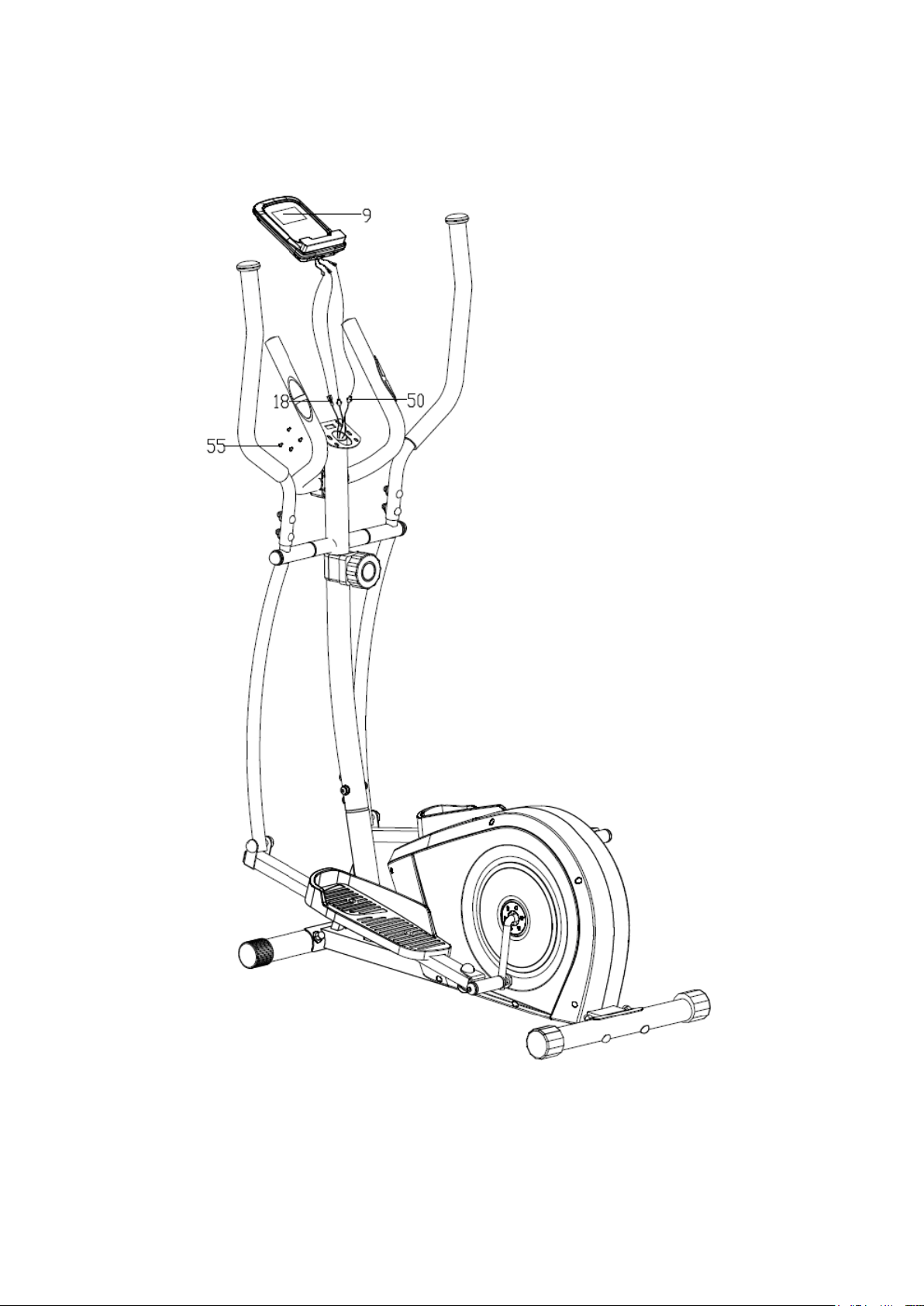
Step 4:
- 9 -
Connect the Pulse sensor wire (50) and Extension wire(18) with the wires coming from the
Computer (9), and then fix the Computer (9) onto the computer bracket of the Handlebar
post (2) with Cross screw (55).
Step 5:

GARLANDO SPA
Via Regione Piemonte, 32 - Zona Industriale D1
15068 - Pozzolo Formigaro (AL) - Italy
www.evert.it - info@evert.it