Loading ...
Loading ...
Loading ...
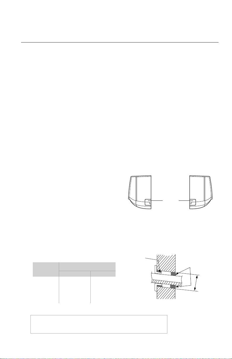
Carefully cut hole in the side of the front panel for piping to enter indoor unit as shown below.
Find and mark the proper location for the wall hole. Use table below to determine recommended
wall hole size for your unit size.
3.
Cut the wall hole with a 5° to 10°
downward slant to the outdoors.
4. Insert a wall sleeve into hole to prevent
damage to refrigerant pipes, insulation,
condensate drain hose and wiring.
5. Proper weather proofing of the wall surface and wall sleeve is essential to
assure a trouble-free installation. Apply sealant, caulking or equivalent weather
proofing material around the perimeter of the wall sleeve (interior & exterior) to
eliminate outdoor air and water leaks into the living space.
Refrigerant Piping
INDOOR UNIT INSTALLATION
NOTE: Expandable foam insulation may be added to fill large
wall gaps. Apply per manufacturer's instructions.
Drill Hole in Wall
If indoor unit refrigerant piping is going to exit from the rear:
1. It is recommended that the refrigerant pipe flare connectors extend through the wall
to the outside. In some situations field-fabricated piping extensions will be required to
extend the indoor unit refrigerant flare connections to the outside of the wall.
2. Use mounting bracket diagrams and dimensions to find and mark the proper location
for the wall hole.
If refrigerant piping is going through the right or left side of front panel
(not allowed on Crown models):
Unit Size
Wall Hole Size (Diameter)
(BtuH)
in mm
9,000 2 1/4 55
12,000 2 1/4 55
18,000 2 3/4 70
24,000 2 3/4 70
Table of Wall Hole Size per Unit Size
Left Side
Cut Piping
Hole
Right Side
20
Seal Hole
Hole Size
Indoor
Outdoor
Wall
Hole Sleeve
Wall Hole Diagram
Loading ...
Loading ...
Loading ...