Uncased
Coils
Upflow
-
Downflow
Heating
-
Cooling
Installation
Instructions
NOTE:
Read
the
entire
instruction
manual
before
starting
the
installation.
TABLE
OF
CONTENTS
PAGE
SAFETY
CONSIDERATIONS
...
0.00.00
eee
1
INTRODUCTION
2.00.6
eee
1
INSTALLATION
2.0...
eee
eee
2
Procedure
1
—
Inspect
Equipment
.................000.
2
Procedure
2
—
Select
Installation
.................00.
3
Procedure
3
—
Installation
of
Evaporator
Coil
...........
4
Procedure
4
—
Connect
Refrigerant
Piping
.............
6
Procedure
5
—
Connect
Refrigerant
Liquid
and
Suction
Lines
.......
0.0.0.0...
0005
6
Procedure
6
—
Condensate
Drain
Line
Connection
.......
7
Procedure
7
—
Humidifier
Application
................
8
SAFETY
CONSIDERATIONS
Improper
installation,
adjustment,
alteration,
service,
maintenance,
or
use
can
cause
explosion,
fire,
electrical
shock,
or
other
conditions
which
may
cause
death,
personal
injury
or
property
damage.
Consult
a
qualified
installer,
service
agency,
or
your
distributor
or
branch
for
information
or
assistance.
The
qualified
installer
or
agency
must
use
factory-
authorized
kits
or
accessories
when
modifying
this
product. Refer
to
the
individual
instructions
packaged
with
the
kits
or
accessories
when
installing.
Follow
all
safety
codes.
Wear
safety
glasses,
protective
clothing,
and
work
gloves.
Use
quenching
cloth
for
brazing
operations.
Have
fire
extinguisher
available.
Read
these
instructions
thoroughly
and
follow
all
warning
or
cautions
included
in
literature
and
attached
to
the
unit.
Consult
local
building
codes
and
the
current
editions
of
the
National
Electrical
Code
(NEC)
NFPA
70.
In
Canada,
refer
to
the
current
editions
of
the
Canadian
Electrical
Code
CSA
C22.1.
Recognize
safety
information.
When
you
see
this
symbol
A\
on
the
unit
and
in
instructions
or
manuals,
be
alert
to
the
potential
for
personal
injury.
Understand
the
signal
words
DANGER,
WARNING,
CAUTION,
and
NOTE.
These
words
are
used
with
the
safety-alert
symbol.
DANGER
identifies
the
most
serious
hazards
which
will
result
in
severe
personal
injury
or
death.
WARNING
signifies
hazards
which
could
result
in
personal
injury
or
death,
CAUTION
is
used
to
identify
unsafe
practices
which
may
result
in
minor
personal
injury
or
product
and
property
damage.
NOTE
is
used
to
highlight
suggestions
which
will
result
in
enhanced
installation,
reliability,
or
operation.
4.
WARNING
ELECTRICAL
SHOCK
HAZARD
Failure
to
follow
this
warning
could
result
in
personal
injury
or
death.
Before
installing
or
servicing
system,
always
turn
off
main
power
to
system.
There
may
be
more
than
one
disconnect
switch.
Tag
disconnect
switch
with
a
suitable
warning
label.
Turn
off
accessory
heater
power
if
applicable.
4&
CAUTION
UNIT
OR
PROPERTY
DAMAGE
HAZARD
Failure
to
follow
this
caution
may
result
in
product
or
property
damage.
This
coil
contains
Nitrogen
precharge
of
15
PSI.
Release
of
this
pressure
through
the
center
of
the
rubber
plugs
is
required
before
removing
the
plugs.
CUT
HAZARD
Failure
to
follow
this
caution
may
result
in
personal
injury.
Sheet metal
parts
may
have
sharp
edges
or
burrs.
Use
care
and
wear
appropriate
protective
clothing
and
gloves
when
handling
parts.
IMPORTANT:
Nitrogen
can
leak
out
through
the
hole
that
the
needle
pierced
in
the
plugs.
This
does
not
indicate
a
leaking
coil
nor
warrant
return
of
the
coil.
INTRODUCTION
Use
this
instruction
manual
to
install
indoor
coils
on
upflow
or
downtflow
furnaces.
(See
Fig.
1.)
Do
not
install
coil
in
horizontal
position.
Models
CNPVU/CNRVU
have
_
factory-
installed
thermostatic
expansion
valves
(TXVs).
CNPVU
models
are
used
with
Puron®
refrigerant
(R410A)
systems
and
CNRVU
models
are
used
with
R- 22
systems.
INSTALLATION
These
units
can
be
installed
in
either
upflow
or
downflow
configurations.
Before
installation,
there
are
several
performance
requirements
that
must
be
considered
because
poor
installation
can
negatively
alter
performance.
This
section
will
briefly
discuss
those
factors.
TXV
A
thermal
expansion
valve
is
utilized
in
this
coil
design
to
optimize
performance
and
comfort
throughout
the
entire
operating
range
of
the
system.
Special
attention
needs
to
be
taken
to
the
TXV
when
installing
the
coil
¢
Do
not
overheat
valve.
Temperatures
that
exceed
212°F
(100°C)
can
harm
valve
performance.
Use
a
wet
cloth
or
heat
sink
when
brazing.
¢
Place
filter
dryer
near
ID
unit
to
reduce
the
risk
of
debris
clogging
the
valve.
¢
Make
sure
TXV
bulb
is
securely
fastened
and
wrapped
in
the
indentation
on
heater
tube.
CNPVU
Models:
These
coils
have
a
factory-
installed
hard-
shutoff
TXV
designed
only
for
use
with
R-
410A
refrigerant.
Use
only
with
outdoor
units
designed
for
R-
410A.
CNRVU
Models:
These
coils
have
a
factory-
installed
hard-
shutoff
TXV
designed
only
for
use
with
R-22
refrigerant.
Use
only
with
outdoor
units
designed
for
R-
22.
NOTE:
All
TXVs
have
preset
superheat
settings
and
are
not
field-
adjustable.
°
Header
Plate
1
pe.
Airflow
Airflow
amount
and
distribution
are
vital
to
adequate
system
performance.
Problems
that
can
be
experienced
with
incorrect
airflow
include:
¢
low
system
performance
¢
restricted
TXV
¢
frosted
coil
*
poor
humidity
control
¢
water
blow-
off
When
attaching
the
coil
and
building
the
plenum,
pay
special
attention
to
the
effect
these
details
will
have
on
airflow.
After
system
start-up,
check
the
cfm
to
insure
that
it
is
correct.
(Generally,
the
cfm
should
be
350
to
400
cfm/ton
during
normal
cooling
operation.)
Condensate
Management
With
proper
installation,
these
coils
will
manage
the
condensate
without
blow-off
into
the
duct
work.
See
detailed
instructions
for
more
info.
Procedure
1
—
Inspect
Equipment
File
claim
with
shipper
if
equipment
is
damaged.
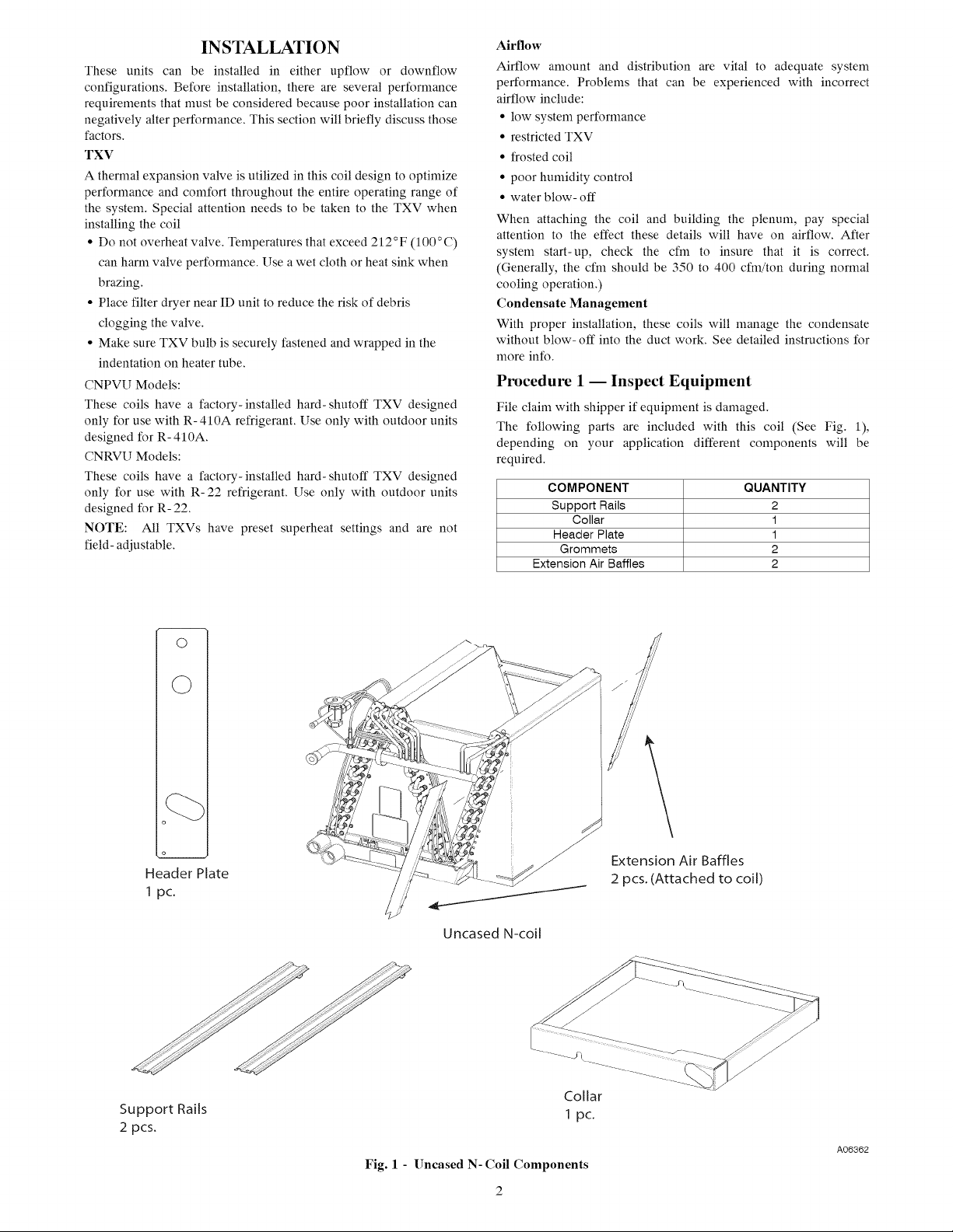
The
following
parts
are
included
with
this
coil
(See
Fig.
1),
depending
on
your
application
different
components
will
be
required.
COMPONENT
QUANTITY
2
Extension
Air
Baffles
2
pcs.
(Attached
to
coil)
Support
Rails
2
pcs.
Collar
1
pe.
A06362
Fig.
1
-
Uncased
N-
Coil
Components
2
Procedure
2
—
Select
Installation
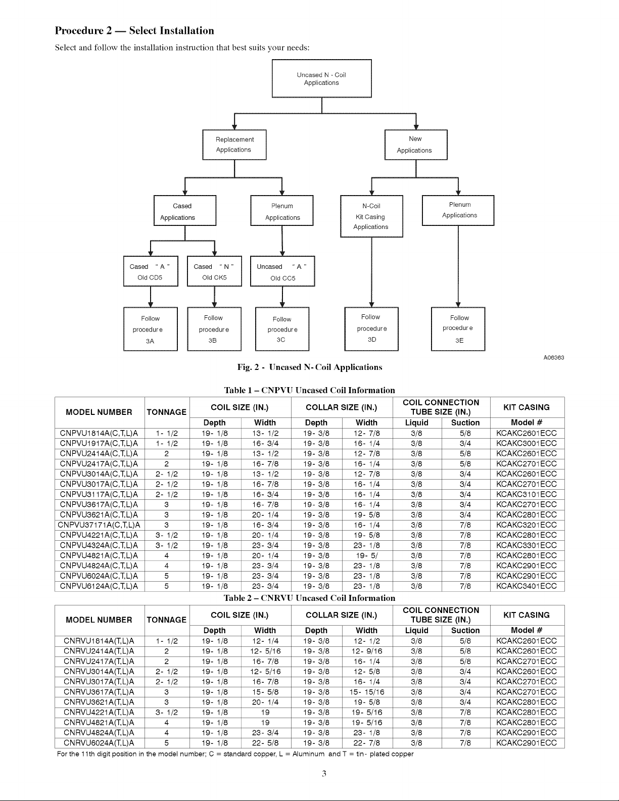
Select
and
follow
the
installation
instruction
that
best
suits
your
needs:
Uncased
N
-
Cail
Applications
Replacement
New
Applications
Applications
v
x x
v
Cased
Plenum
N-Goil
Plenum
Applications Applications
Kit
Casing
Applications
Applications
x
Cased
“A”
Cased
“N”
Uncased
“A”
Old
CDS
Old
CK5
Old
CCS
V.
7 7
Vv
Vv.
Follow
Follow
Follow
Follow
Follow
procedure procedure procedure
procedure
procedure
3A
3B
3c
3D
3E
A06363
Fig.
2
-
Uncased
N-
Coil
Applications
Table
1
-
CNPVU
Uncased
Coil
Information
COIL
CONNECTION
MODEL
NUMBER
TONNAGE
COIL
SIZE
(IN.)
COLLAR
SIZE
(IN.)
TUBE
SIZE
(IN.)
KIT
CASING
Depth
Width
Depth
Width
Liquid
Suction
Model
#
CNPVU1814A(C,
ELA
1-1/2
19-
1/8
13-
1/2
19-
3/8
12-
7/8
3/8 5/8
KCAKC2601ECC
CNPVU1917A(C,
ELA
1-1/2
19-
1/8
16-
3/4
19-
3/8
16-
1/4
3/8 3/4
KCAKC3001ECC
CNPVU2414A(C,
TL
L)A
2
19-
1/8
13-
1/2
19-
3/8
12-
7/8
3/8 5/8
KCAKC2601ECC
CNPVU2417A(C,
TL
L)A
2
19-
1/8
16-
7/8
19-
3/8
16-
1/4
3/8 5/8
KCAKC2701ECC
CNPVUS014A(C,
TL
L)JA
2-
1/2
19-
1/8
13-
1/2
19-
3/8
12-
7/8
3/8 3/4
KCAKC2601ECC
CNPVU38017A(C,
TL
L)A
2-
1/2
19-
1/8
16-
7/8
19-
3/8
16-
1/4
3/8 3/4
KCAKC2701ECC
CNPVU38117A(C,
ELA
2-
1/2
19-
1/8
16-
3/4
19-
3/8
16-
1/4
3/8 3/4
KCAKC3101ECC
CNPVU3617A(C,
TE
L)JA
3
19-
1/8
16-
7/8
19-
3/8
16-
1/4
3/8 3/4
KCAKC2701ECC
CNPVUS8621A(C,
TELIA
3
19-
1/8
20-
1/4
19-
3/8
19-
5/8
3/8 3/4
KCAKC2801ECC
CNPVU87171A(C,T.LA
3
19-
1/8
16-
3/4
19-
3/8
16-
1/4
3/8 7/8
KCAKC3201ECC
CNPVU4221A(C,
ELA
3-
1/2
19-
1/8
20-
1/4
19-
3/8
19-
5/8
3/8 7/8
KCAKC2801ECC
CNPVU4324A(C,
TL
L)A
3-
1/2
19-
1/8
23-
3/4
19-
3/8
23-
1/8
3/8 7/8
KCAKC83301ECC
CNPVU4821A(C,
ELA
4
19-
1/8
20-
1/4
19-
3/8
19-
5/
3/8
7/8
KCAKC2801ECC
CNPVU4824A(C,
TL
L)A
4
19-
1/8
23-
3/4
19-
3/8
23-
1/8
3/8 7/8
KCAKC2901ECC
CNPVU6024A(C,
TLIA
5
19-
1/8
23-
3/4
19-
3/8
23-
1/8
3/8 7/8
KCAKC2901ECC
CNPVU6124A(C,
TL
L)IA
5
19-
1/8
23-
3/4
19-
3/8
23-
1/8
3/8 7/8
KCAKC3401ECC
Table
2
-
CNRVU
Uncased
Coil
Information
COIL
CONNECTION
MODEL
NUMBER
TONNAGE
COIL
SIZE
(IN.)
COLLAR
SIZE
(IN.)
TUBE
SIZE
(IN.)
KIT
CASING
Depth
Width
Depth
Width
Liquid
Suction
Model
#
CNRVU1814A(T.
LA
1-1/2
19-
1/8
12-
1/4
19-
3/8
12-
1/2
3/8 5/8
KCAKC2601ECC
CNRVU2414A(T.
LA
2
19-
1/8
12-
5/16
19-
3/8
12-
9/16
3/8 5/8
KCAKC2601ECC
CNRVU2417A(T.L)A
2
19-
1/8
16-
7/8
19-
3/8
16-
1/4
3/8 5/8
KCAKC2701ECC
CNRVU3014A(T.
LA
2-
1/2
19-
1/8
12-
5/16
19-
3/8
12-
5/8
3/8 3/4
KCAKC2601ECC
CNRVU301
7A(T.LIA
2-
1/2
19-
1/8
16-
7/8
19-
3/8
16-
1/4
3/8 3/4
KCAKC2701ECC
CNRVU361
7A(T.LIA
3
19-
1/8
15-
5/8
19-
3/8
15-
15/16
3/8 3/4
KCAKC2701ECC
CNRVU3621A(T.LIA
3
19-
1/8
20-
1/4
19-
3/8
19-
5/8
3/8 3/4
KCAKC2801ECC
CNRVU4221
A(T.
LIA
3-
1/2
19-
1/8
19
19-
3/8
19-
5/16
3/8 7/8
KCAKC2801ECC
CNRVU4821A(T.L)A
4
19-
1/8
19
19-
3/8
19-
5/16
3/8 7/8
KCAKC2801ECC
CNRVU4824A(T,
LJA
4
19-
1/8
23-
3/4
19-
3/8
23-
1/8
3/8 7/8
KCAKC2901ECC
CNRVU6024A(T,LJA
5
19-
1/8
22-
5/8
19-
3/8
22-
7/8
3/8 7/8
KCAKC2901ECC
For
the
11th
digit
position
in
the
model
number;
C =
standard
copper,
L
=
Aluminum
and
T
=
tin-
plated
copper
3
See
Table
1
and
2
for
dimensions
and
overhang
options.
Note
instructions
for
placement
of
coil
casing
on
furnace.
For
replacement
applications
using
an
existing
CD5
coil
assembly
follow
Procedure
3A.
For
replacement
applications
using
an
existing
CK5
coil
assembly
follow
Procedure
3B.
For
replacement
applications
using
an
existing
uncased
A-coil
plenum
installation
follow
Procedure
3C.
For
new
applications
using
a
KCAKC
N-coil
kit
casing
follow
Procedure
3D.
For
new
applications
using
a
field-
fabricated
plenum
installation
follow
Procedure
3E.
Procedure
3
—
Installation
of
Evaporator
Coil
4&
CAUTION
UNIT
OR
PROPERTY
DAMAGE
HAZARD
Failure
to
follow
this
caution
may
result
in
product
or
property
damage.
Take
precautions
to
ensure
that
aluminum
tubes
do no
come
in
direct
contact
or
allow
for
condensate
runoff
with
dissimilar
metal.
Dissimilar
metals
can
cause
galvanic
corrosion
and
possible
premature
failure.
4&
CAUTION
CUT
HAZARD
Failure
to
follow
this
caution
may
result
in
personal
injury.
Sheet metal
parts
may
have
sharp
edges
or
burrs.
Use
care
and
wear
appropriate
protective
clothing
and
gloves
when
handling
parts.
3A.
Upflow
and
downflow
applications
using
an
existing
CD5
coil
casing.
1.
Remove
and
keep
front
access
and
tubing
header
panel.
.
Remove
old
A-
coil
from
casing
and
discard
coil.
Ww
.
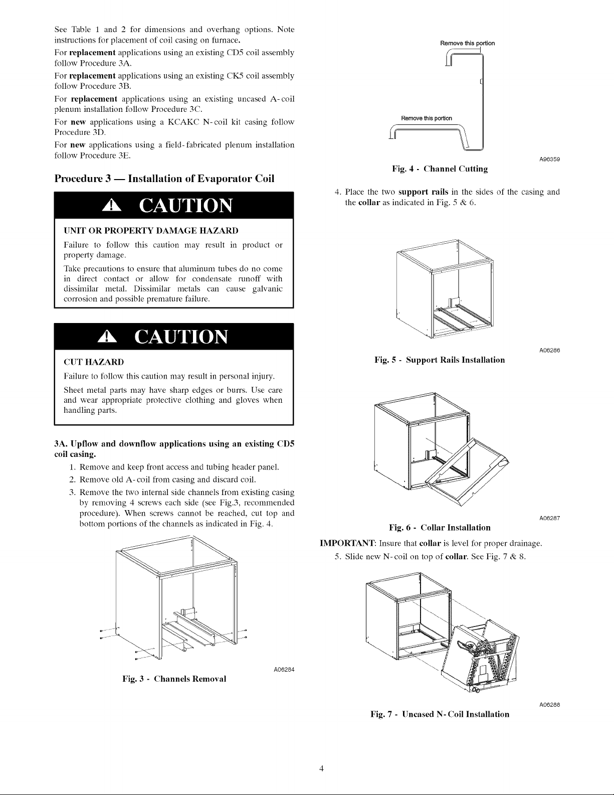
Remove
the
two
internal
side
channels
from
existing
casing
by
removing
4
screws
each
side
(see
Fig.3,
recommended
procedure).
When
screws cannot
be
reached,
cut
top
and
bottom
portions
of
the
channels
as
indicated
in
Fig.
4.
A06284
Fig.
3
-
Channels
Removal
Remove
this
portion
(oO
q
Remove
this
portion
Fig.
4
-
Channel
Cutting
AQ96359
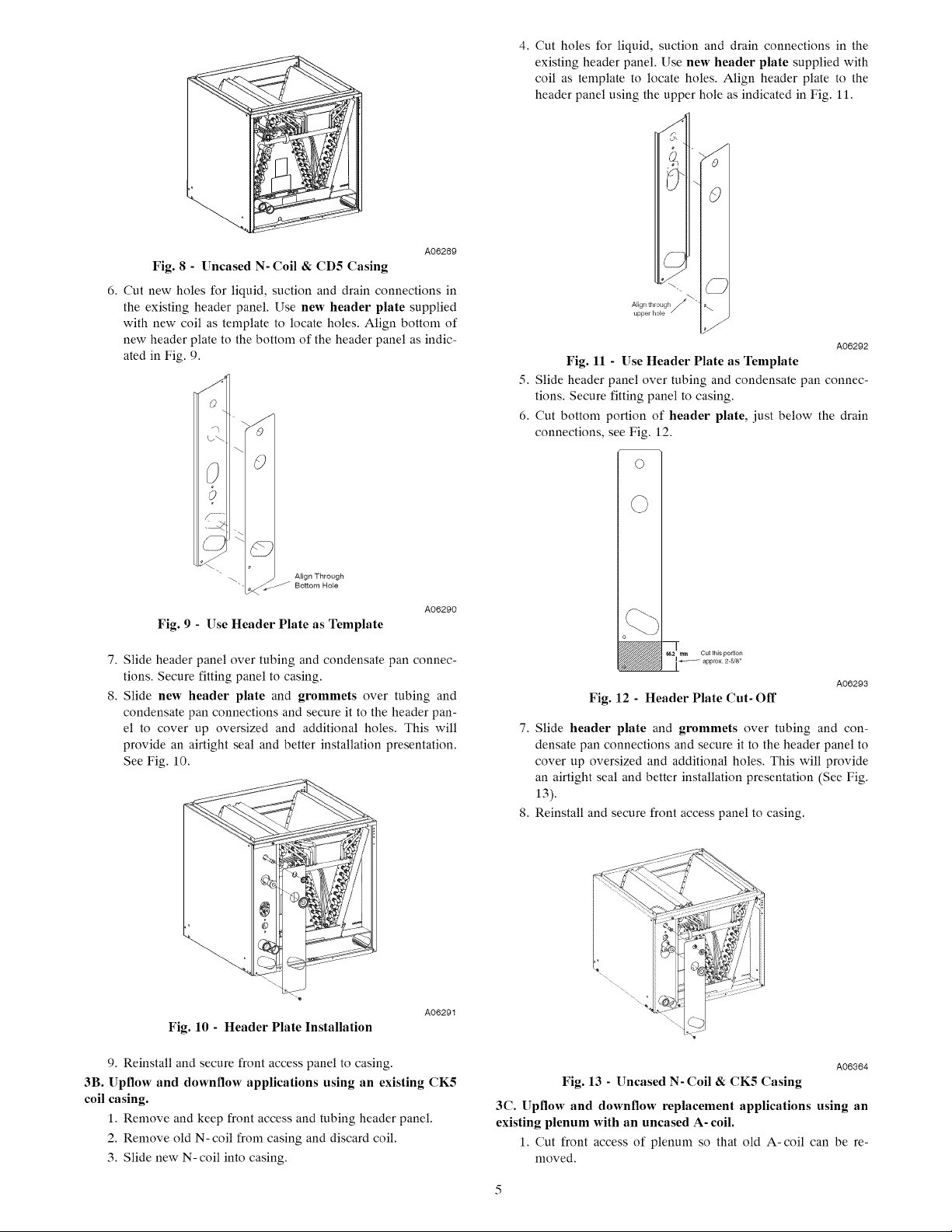
4.
Place
the
two
support
rails
in
the
sides
of
the
casing
and
the
collar
as
indicated
in
Fig.
5
&
6.
A06286
Fig.
5
-
Support
Rails
Installation
A06287
Fig.
6
-
Collar
Installation
IMPORTANT:
Insure
that
collar
is
level
for
proper
drainage.
5.
Slide
new
N-coil
on
top
of
collar.
See
Fig.
7
&
8.
A06288
Fig.
7
-
Uncased
N-
Coil
Installation
A06289
Fig.
8
-
Uncased
N-
Coil
&
CDS5
Casing
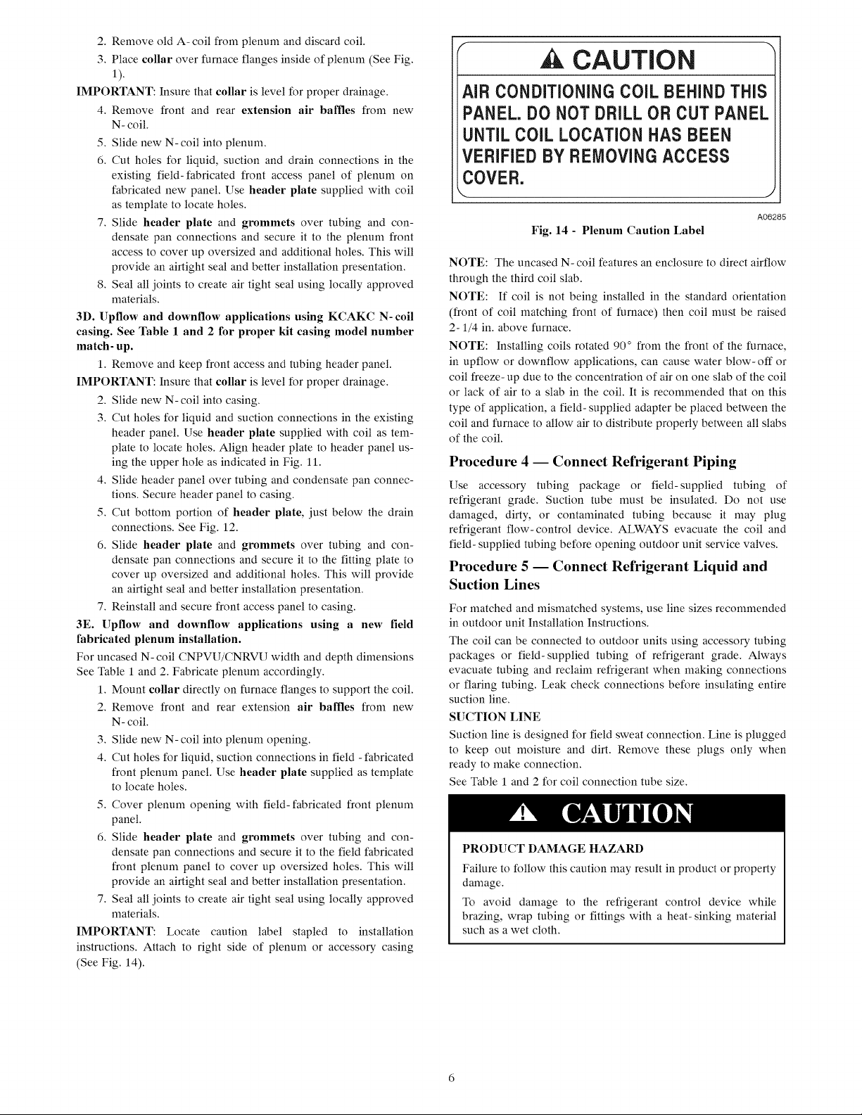
6.
Cut
new
holes
for
liquid,
suction
and
drain
connections
in
the
existing
header
panel.
Use
new
header
plate
supplied
with
new
coil
as
template
to
locate
holes.
Align
bottom
of
new
header
plate
to
the
bottom
of
the
header
panel
as
indic-
ated
in
Fig.
9.
Align
Through
~~
Bottom
Hole
A06290
Fig.
9
-
Use
Header
Plate
as
Template
7,
Slide
header
panel over
tubing
and
condensate
pan
connec-
tions.
Secure
fitting
panel
to
casing.
8.
Slide
new
header
plate
and
grommets
over
tubing
and
condensate
pan
connections
and
secure
it
to
the
header
pan-
el
to
cover
up
oversized
and
additional
holes.
This
will
provide
an
airtight
seal
and
better
installation
presentation.
See
Fig.
10.
A06291
Fig.
10
-
Header
Plate
Installation
9,
Reinstall
and
secure
front
access
panel
to
casing.
3B.
Upflow
and
downflow
applications
using
an
existing
CK5
coil
casing.
1.
Remove
and
keep
front
access
and
tubing
header
panel.
2.
Remove
old
N-
coil
from
casing
and
discard
coil.
3.
Slide
new
N-
coil
into
casing.
4.
Cut
holes
for
liquid,
suction
and
drain
connections
in
the
existing
header
panel.
Use
new
header
plate
supplied
with
coil
as
template
to
locate
holes.
Align
header
plate
to
the
header
panel
using
the
upper
hole
as
indicated
in
Fig.
11.
e
~,
Align
through
upper
hole
a
Aoe292
Fig.
11
-
Use
Header
Plate
as
Template
5.
Slide
header
panel over
tubing
and
condensate
pan
connec-
tions.
Secure
fitting
panel
to
casing.
6.
Cut
bottom
portion
of
header
plate,
just
below
the
drain
connections,
see
Fig.
12.
O
O
SS
°
62
mm
Cul
this
portion
fa
approx.
2-5/8"
Fig.
12
-
Header
Plate
Cut-
Off
A06293
7,
Slide
header
plate
and
grommets
over
tubing
and
con-
densate
pan
connections
and
secure
it
to
the
header
panel
to
cover
up
oversized
and
additional
holes.
This
will
provide
an
airtight
seal
and
better
installation
presentation
(See
Fig.
13).
8.
Reinstall
and
secure
front
access
panel
to
casing.
A06364
Fig.
13
-
Uncased
N-
Coil
&
CK5
Casing
3C.
Upfiow
and
downflow
replacement
applications
using
an
existing
plenum
with
an
uncased
A-
coil.
1.
Cut
front
access
of
plenum
so
that
old
A-coil
can
be
re-
moved.
2.
Remove
old
A-coil
from
plenum
and
discard
coil.
3.
Place
collar
over
furnace
flanges
inside
of
plenum
(See
Fig.
1).
IMPORTANT:
Insure
that
collar
is
level
for
proper
drainage.
4.
Remove
front
and
rear
extension
air
baffles
from
new
N-
coil.
5.
Slide
new
N-coil
into
plenum.
6.
Cut
holes
for
liquid,
suction
and
drain
connections
in
the
existing
field-fabricated
front
access
panel
of
plenum
on
fabricated
new
panel.
Use
header
plate
supplied
with
coil
as
template
to
locate
holes.
7,
Slide
header
plate
and
grommets
over
tubing
and
con-
densate
pan
connections
and
secure
it
to
the
plenum
front
access
to
cover
up
oversized
and
additional
holes.
This
will
provide
an
airtight
seal
and
better
installation
presentation.
8.
Seal
all
joints
to
create
air
tight
seal
using
locally
approved
materials.
3D.
Upflow
and
downflow
applications
using
KCAKC
N-
coil
casing.
See
Table
1
and
2
for
proper
kit
casing
model
number
match-up.
1.
Remove
and
keep
front
access
and
tubing
header
panel.
IMPORTANT:
Insure
that
collar
is
level
for
proper
drainage.
.
Slide
new
N-
coil
into
casing.
Ww
be
.
Cut
holes
for
liquid
and
suction
connections
in
the
existing
header
panel.
Use
header
plate
supplied
with
coil
as
tem-
plate
to
locate
holes.
Align
header
plate
to
header
panel
us-
ing
the
upper
hole
as
indicated
in
Fig.
11.
4.
Slide
header
panel over
tubing
and
condensate
pan
connec-
tions.
Secure header
panel
to
casing.
5.
Cut
bottom
portion
of
header
plate,
just
below
the
drain
connections.
See
Fig.
12.
6.
Slide
header
plate
and
grommets
over
tubing
and
con-
densate
pan
connections
and
secure
it
to
the
fitting
plate
to
cover
up
oversized
and
additional
holes.
This
will
provide
an
airtight
seal
and
better
installation
presentation.
7.
Reinstall
and
secure
front
access
panel
to
casing.
3E.
Upflow
and
downflow
applications
using
a
new
field
fabricated
plenum
installation.
For
uncased
N-
coil
CNPVU/CNRVU
width
and
depth
dimensions
See
Table
1
and
2.
Fabricate
plenum
accordingly.
1.
Mount
collar
directly
on
furnace
flanges
to
support
the
coil.
2.
Remove
front
and
rear
extension
air
baffles
from
new
N-
coil.
3.
Slide
new
N-
coil
into
plenum
opening.
4,
Cut
holes
for
liquid,
suction
connections
in
field
-
fabricated
front
plenum
panel.
Use
header
plate
supplied
as
template
to
locate
holes.
5.
Cover
plenum
opening
with
field-
fabricated
front
plenum
panel.
6.
Slide
header
plate
and
grommets
over
tubing
and
con-
densate
pan
connections
and
secure
it
to
the
field
fabricated
front
plenum
panel
to
cover
up
oversized
holes.
This
will
provide
an
airtight
seal
and
better
installation
presentation.
7.
Seal
all
joints
to
create
air
tight
seal
using
locally
approved
materials.
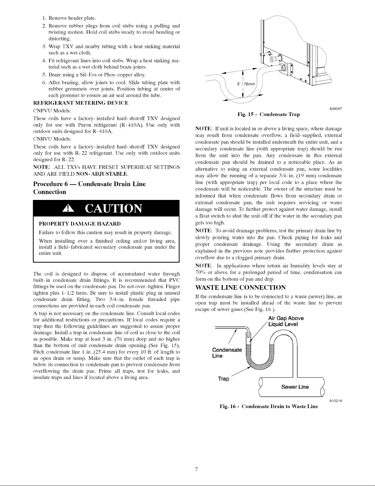
IMPORTANT:
Locate
caution
label
stapled
to
installation
instructions.
Attach
to
right
side
of
plenum
or
accessory
casing
(See
Fig.
14).
(
A
CAUTION
)
AIR
CONDITIONING
COIL
BEHIND
THIS
PANEL.
DO
NOT
DRILL
OR
CUT
PANEL
UNTIL
COIL
LOCATION
HAS
BEEN
VERIFIED
BY
REMOVING
ACCESS
COVER.
A06285
Fig.
14
-
Plenum
Caution
Label
NOTE:
The
uncased
N-
coil
features
an
enclosure
to
direct
airtlow
through
the
third
coil
slab.
NOTE:
If
coil
is
not
being
installed
in
the
standard
orientation
(front
of
coil
matching
front
of
furnace)
then
coil
must
be
raised
2-1/4
in.
above
furnace.
NOTE:
Installing
coils
rotated 90°
from
the
front
of
the
furnace,
in
upflow
or
downflow
applications,
can
cause
water
blow-
off
or
coil
freeze-
up
due
to
the
concentration
of
air
on
one
slab
of
the
coil
or
lack
of
air
to
a
slab
in
the
coil.
It
is
recommended
that
on
this
type
of
application,
a
field-
supplied
adapter
be
placed
between
the
coil
and
furnace
to
allow
air
to
distribute
properly
between
all
slabs
of
the
coil.
Procedure
4
—
Connect
Refrigerant
Piping
Use
accessory
tubing
package
or
field-supplied
tubing
of
refrigerant
grade.
Suction
tube
must
be
insulated.
Do
not
use
damaged,
dirty,
or
contaminated
tubing
because
it
may
plug
refrigerant
flow-
control
device.
ALWAYS
evacuate
the
coil
and
fieid-
supplied
tubing
before
opening
outdoor
unit
service valves.
Procedure
5
—
Connect
Refrigerant
Liquid
and
Suction
Lines
For
matched
and
mismatched
systems,
use
line
sizes
recommended
in
outdoor
unit
Installation
Instructions.
The
coil
can
be
connected
to
outdoor
units
using
accessory
tubing
packages
or
field-supplied
tubing
of
refrigerant
grade.
Always
evacuate
tubing
and
reclaim
refrigerant
when
making
connections
or
flaring
tubing.
Leak
check
connections
before
insulating
entire
suction
line.
SUCTION
LINE
Suction
line
is
designed
for
field
sweat
connection.
Line
is
plugged
to
keep
out
moisture
and
dirt.
Remove
these
plugs
only
when
ready
to
make
connection.
See
Table
1
and
2
for
coil
connection
tube
size.
PRODUCT
DAMAGE
HAZARD
Failure
to
follow
this
caution
may
result
in
product
or
property
damage.
To
avoid
damage
to
the
refrigerant
control
device
while
brazing,
wrap
tubing
or
fittings
with
a
heat-sinking
material
such
as
a
wet
cloth.
1.
Remove
header
plate.
bo
.
Remove
rubber
plugs
from
coil
stubs
using
a
pulling
and
twisting
motion.
Hold
coil
stubs
steady
to
avoid
bending
or
distorting.
3.
Wrap
TXV
and
nearby
tubing
with
a
heat
sinking
material
such
as
a
wet
cloth.
4.
Fit
refrigerant
lines
into
coil
stubs.
Wrap
a
heat
sinking
ma-
terial
such
as
a
wet
cloth
behind
braze
joints.
5.
Braze
using
a
Sil-
Fos
or
Phos-
copper
alloy.
6.
After
brazing,
allow
joints
to
cool.
Slide
tubing
plate
with
rubber
grommets
over
joints.
Position
tubing
at
center
of
each
grommet
to
ensure
an
air
seal
around
the
tube.
REFRIGERANT
METERING
DEVICE
CNPVU
Models:
These
coils
have
a
factory-
installed
hard-
shutoff
TXV
designed
only
for
use
with
Puron
refrigerant
(R-410A).
Use
only
with
outdoor
units
designed
for
R-
410A.
CNRVU
Models:
These
coils
have
a
factory-
installed
hard-
shutoff
TXV
designed
only
for
use
with
R-22
refrigerant.
Use
only
with
outdoor
units
designed
for
R-
22.
NOTE:
ALL
TXVs
HAVE
PRESET
SUPERHEAT
SETTINGS
AND
ARE
FIELD
NON-
ADJUSTABLE.
Procedure
6
—
Condensate
Drain
Line
Connection
4&
CAUTION
PROPERTY
DAMAGE
HAZARD
Failure
to
follow
this
caution
may
result
in
property
damage.
When
installing
over
a
finished
ceiling
and/or
living
area,
install
a
field-
fabricated
secondary
condensate
pan
under
the
entire
unit.
The
coil
is
designed
to
dispose
of
accumulated
water
through
built-in
condensate
drain
fittings.
It
is
recommended
that
PVC
fittings be
used
on
the
condensate
pan.
Do
not
over-
tighten.
Finger
tighten
plus
1-1/2
turns.
Be
sure
to
install
plastic
plug
in
unused
condensate
drain
fitting.
Two
3/4-in.
female
threaded
pipe
connections
are
provided
in
each
coil
condensate
pan.
A
trap
is
not
necessary
on
the
condensate
line.
Consult
local
codes
for
additional
restrictions
or
precautions.
If
local
codes
require
a
trap
then
the
following
guidelines
are
suggested
to
assure
proper
drainage.
Install
a
trap
in
condensate
line
of
coil
as
close
to
the
coil
as
possible.
Make
trap
at
least
3
in.
(76
mm)
deep
and
no
higher
than
the
bottom
of
unit
condensate
drain
opening
(See
Fig.
15).
Pitch
condensate
line
1
in.
(25.4
mm)
for
every
10
ft.
of
length
to
an
open
drain
or
sump.
Make
sure
that
the
outlet
of
each
trap
is
below
its
connection
to
condensate
pan
to
prevent
condensate
from
overflowing
the
drain
pan.
Prime
all
traps,
test
for
leaks,
and
insulate
traps
and
lines
if
located
above
a
living
area.
A08067
Fig.
15
-
Condensate
Trap
NOTE:
If
unit
is
located
in
or
above
a
living
space,
where
damage
may
result
from
condensate
overflow,
a
field-
supplied,
external
condensate
pan
should
be
installed
underneath
the
entire
unit,
and
a
secondary
condensate
line
(with
appropriate
trap)
should
be
run
from
the
unit
into
the
pan.
Any
condensate
in
this
external
condensate
pan
should
be
drained
to
a
noticeable
place.
As
an
alternative
to
using
an
external
condensate
pan,
some
localities
may
allow
the
running
of
a
separate
3/4-in.
(19
mm)
condensate
line
(with
appropriate
trap)
per local
code
to
a
place
where
the
condensate
will
be
noticeable.
The
owner
of
the
structure
must
be
informed
that
when
condensate
flows
from
secondary
drain
or
external
condensate
pan,
the
unit
requires
servicing
or
water
damage
will
occur.
To
further
protect
against
water
damage,
install
a
float
switch
to
shut
the
unit
off
if
the
water
in
the
secondary
pan
gets
too
high.
NOTE:
To
avoid
drainage
problems,
test
the
primary
drain
line
by
slowly
pouring
water
into
the
pan.
Check
piping
for
leaks
and
proper
condensate
drainage.
Using
the
secondary
drain
as
explained
in
the
previous
note
provides
further
protection
against
overflow
due
to
a
clogged
primary
drain.
NOTE:
In
applications
where
return
air
humidity
levels
stay
at
70%
or
above
for
a
prolonged
period
of
time,
condensation
can
form
on
the
bottom
of
pan
and
drip.
WASTE
LINE
CONNECTION
If
the
condensate
line
is
to
be
connected
to
a
waste
(sewer)
line,
an
open
trap
must
be
installed
ahead
of
the
waste
line
to
prevent
escape
of
sewer
gases
(See
Fig.
16
).
Air
Gap
Above
Liquid
Level
Condensate
Line
Trap
Sewer
Line
A10216
Fig.
16
-
Condensate
Drain
to
Waste
Line
4.
WARNING
EXPLOSION
HAZARD
Failure
to
follow
this
warning
could
result
in
personal
injury
or
death.
Provide
trap
with
air
gap
in
drain
line
when
connecting
to
waste
(sewer)
line.
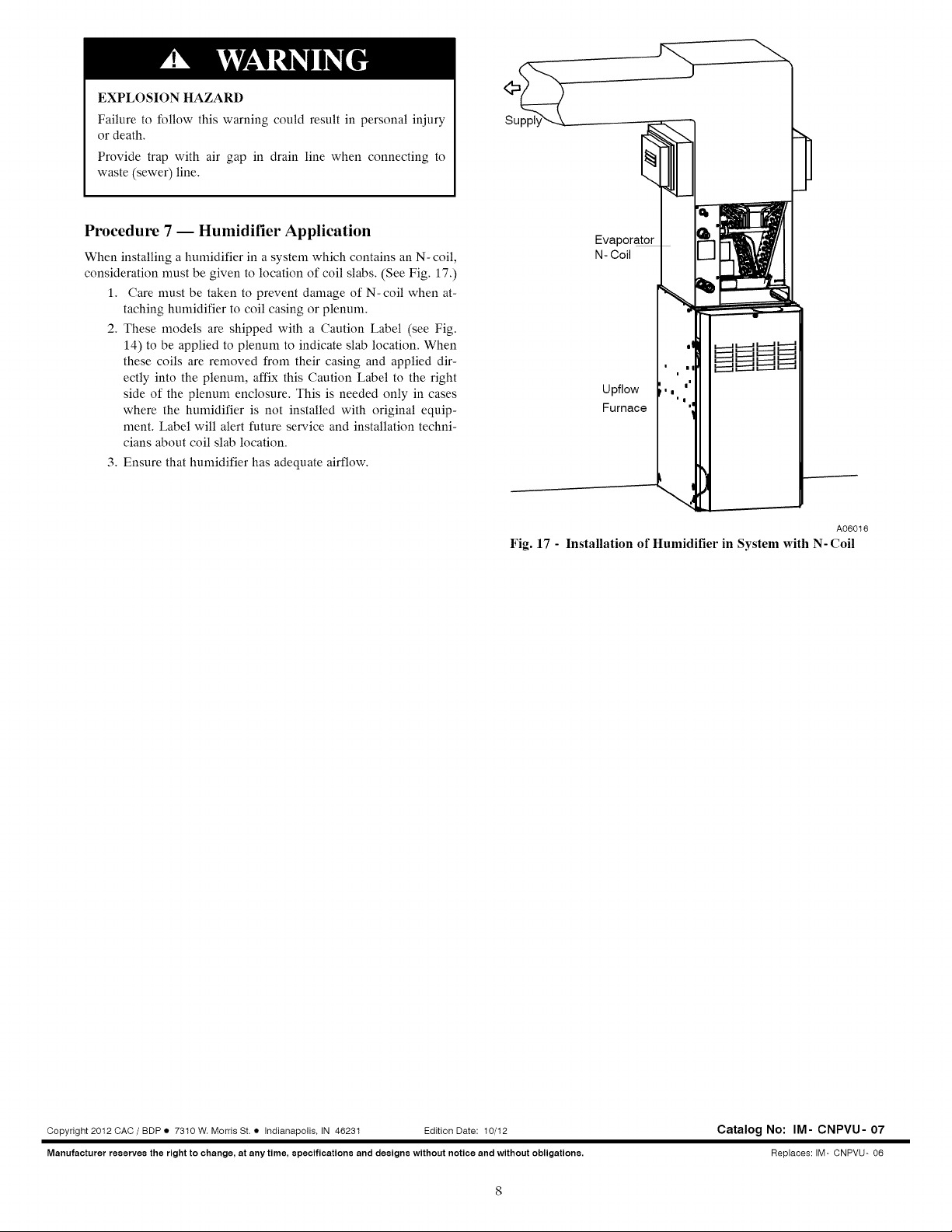
Procedure
7
—
Humidifier
Application
When
installing
a
humidifier
in
a
system
which
contains
an
N-
coil,
consideration
must
be
given
to
location
of
coil
slabs.
(See
Fig.
17.)
1.
Care
must
be
taken
to
prevent
damage
of
N-
coil
when
at-
taching
humidifier
to
coil
casing
or
plenum.
bo
.
These
models
are
shipped
with
a
Caution
Label
(see Fig.
14)
to
be
applied
to
plenum
to
indicate
slab
location.
When
these
coils
are
removed
from
their
casing
and
applied
dir-
ectly
into
the
plenum,
affix
this
Caution
Label
to
the
right
side
of
the
plenum
enclosure.
This
is
needed
only
in
cases
where
the
humidifier
is
not
installed
with
original
equip-
ment.
Label
will
alert
future
service
and
installation
techni-
cians
about
coil
slab
location.
3.
Ensure
that
humidifier
has
adequate
airflow.
Supply
Evaporator
N-
Coil
Upflow
Furnace
_
a
C1
(1
(Mt
(1
(110
A06016
Fig.
17
-
Installation
of
Humidifier
in
System
with
N-
Coil
Copyright
2012
CAC
/
BDP
®
7310
W.
Morris
St.
@
Indianapolis,
IN
46231
Edition
Date:
10/12
Catalog
No:
IM-
CNPVU-
07
Manufacturer
reserves
the
right
to
change,
at
any
time,
specifications
and
designs
without
notice
and
without
obligations.
Replaces:
IM-
CNPVU-
06