Thank you for selecting our quality appliance. Please be sure to read this user manual
carefully before using. Any question, please contact the professional service for help.
Split AC
HME030356N
HME030357N
HME030358N
HME030359N
HME030363N
HME030364N

BEFORE FIRST USE:
The Split AC contains both Indoor (Part 1) and Outdoor (Part 2)
units, these main unit parts are shipped separately in two boxes.
Start installation only once you have received both part boxes. It
is recommended to have the Split AC professionally installed by
HVAC specialist.
In the event this product malfunctions or customer believes
it is defective, the customer should contact Customer Service
and retain the defective product pending further instructions.
Defective product should be clearly marked or stored where it
cannot be used again by mistake. Failure to retain the product
may impede hOme
™
’s ability to correct any legitimate problem
and may limit the extent to which hOme
™
may provide recourse.

Important Safety Instructions
Operating Instructions
Cleaning and Maintenance
Accessories
Installation
Refrigerant Piping Connection
Air Evacuation
Electrical Requirements
Test Run
Impedance Information
Troubleshooting
Warranty
Manufacturing Info
Warning
Contact Us
6-9
10-22
23-25
26
27-38
39-41
42-43
44
45
46
47-49
50
50
50
50
TABLE OF CONTENTS


on bringing home your new appliance!
Congratulations
Don’t forget to register your product at homelabs.com/reg
for updates, coupons, and other relevant information.
Although greatly appreciated, product registration is not
required to activate any warranty.

6
Read Safety Precautions Before Operation and Installation
Incorrect installation due to ignoring instructions can cause serious damage or injury. The seriousness of
WARNING
This symbol indicates the possibility of personnel injury or loss of life.
CAUTION
This symbol indicates the possibility of property damage or serious consequences.
WARNING
• This appliance is not intended for use by persons (including children) with reduced physical, sensory
or mental capabilities, or lack of experience and knowledge, unless they have been given supervision
or instruction concerning use of the appliance by a person responsible for their safety. Children
should be supervised to ensure that they do not play with the appliance.
WARNINGS FOR PRODUCT USE
• If an abnormal situation arises (like a burning smell), immediately turn off the unit and disconnect
•
high speeds. This may cause injury.
•
combustion.
• Do not operate the air conditioner in places near or around combustible gases. Emitted gas may
collect around the unit and cause explosion.
• Do not operate your air conditioner in a wet room such as a bathroom or laundry room. Too much
exposure to water can cause short circuit.
• Do not expose your body directly to cool air for a prolonged period of time.
• Do not allow children to play with the air conditioner. Children must be supervised around the unit at
all times.
• If the air conditioner is used together with burners or other heating devices, thoroughly ventilate the
• In certain functional environments, such as kitchens, server rooms, etc., the use of specially designed
air-conditioning units is highly recommended.
CLEANING AND MAINTENANCE WARNINGS
• Turn off the device and disconnect the power before cleaning. Failure to do so can cause electrical shock.
• Do not clean the air conditioner with excessive amounts of water.
• Do not clean the air conditioner with combustible cleaning agents. Combustible cleaning agents can
CAUTION
• Turn off the air conditioner and disconnect the power if you are not going to use it for a long time.
• Turn off and unplug the unit during storms.
• Make sure that water condensation can drain unhindered from the unit.
• Do not operate the air conditioner with wet hands. This may cause electric shock.
Important Safety Instructions

7
Important Safety Instructions
• Do not use this unit for any other purpose than its intended use.
• Do not climb onto or place objects on top of the outdoor unit.
• Do not allow the air conditioner to operate for long periods of time with doors or windows open, or if
the humidity is very high.
ELECTRICAL WARNINGS
•
• Keep the power plug clean. Remove any dust or grime that accumulates on or around the plug. Dirty
•
• Do not modify the length of the power supply cord or use an extension cord to power the unit. Do
• The product must be properly grounded at the time of installation, or electrical shock may occur. For all
electrical work, follow all local and national wiring standards, regulations, and the Installation Manual.
• Connect cables tightly, and clamp them securely to prevent external forces from damaging the
electrical connections must be made according to the Electrical Connection Diagram located on the
panels of the indoor and outdoor units.
• All wiring must be properly arranged to ensure that the control board cover can close properly. If the
control board cover is not closed properly, it can lead to corrosion and cause the connection points
•
clearances in all poles, and have a leakage current that may exceed 10mA, the residual current device
(RCD) having a rated residual operating current not exceeding 30mA, and disconnection must be
TAKE NOTE OF FUSE SPECIFICATIONS
• The air conditioner’s circuit board (PCB) is designed with a fuse to provide over-current protection.
NOTE:
For the units with R32 or R290 refrigerant , only the blast-proof ceramic fuse can be used.
WARNINGS FOR PRODUCT INSTALLATION
•
• Installation must be performed according to the installation instructions. Improper installation can
• In North America, installation must be performed in accordance with the requirement of NEC and

8
•
be installed in accordance with national wiring regulations.
•
•
support the unit’s weight, or the installation is not done properly, the unit may drop and cause
serious injury and damage.
• Install drainage piping according to the instructions in this manual. Improper drainage may cause
water damage to your home and property.
• For units that have an auxiliary electric heater, do not install the unit within 3 feet of any
combustible materials.
• Do not install the unit in a location that may be exposed to combustible gas leaks. If combustible
• Do not turn on the power until all work has been completed.
• When moving or relocating the air conditioner, consult experienced service technicians for
disconnection and re-installation of the unit.
• For installing the appliance to its support, read the information for details in “indoor unit installation”
and “outdoor unit installation” sections.
•
•
•
equivalent or more, but of less than 50 tonnes of CO2 equivalent, if the system has a leak- detection
system installed, it must be checked for leaks at least every 24 months.
• When the unit is checked for leaks, proper record-keeping of all checks is strongly recommended.
WARNING FOR USING R32/R290 REFRIGERANT
•
Appliance shall not be installed in an unventilated space, if that space is smaller than 4m.
•
allowable pressure. When mechanical connectors are reused indoors, sealing parts shall be renewed.
•
Important Safety Instructions

9
SPECIAL NOTICE
• Disposing of this appliance in the forest or other natural surroundings endangers your health and is bad
FCC STATEMENT
The device could comply with the local national regulations. In USA, this device complies with part 15 of
(1) This device may not cause harmful interference, and
(2) This device must accept any interference received, including interference that may cause undesired
operation.
This equipment has been tested and found to comply with the limits for a Class B digital device, pursuant
to part 15 of the FCC Rules. These limits are designed to provide reasonable protection against harmful
interference in a residential installation. This equipment generates, uses and can radiate radio frequency
energy and, if not installed and used in accordance with the instructions, may cause harmful interference
to radio communications. However, there is no guarantee that interference will not occur in a particular
installation. If this equipment does cause harmful interference to radio or television reception, which
can be determined by turning the equipment off and on, the user is encouraged to try to correct the
• Reorient or relocate the receiving antenna.
• Increase the separation between the equipment and receiver.
• Connect the equipment into an outlet on a circuit different from that to which the receiver is connected.
•
•
authority to operate the equipment.
SAVE THESE INSTRUCTIONS
For Household Use Only
Important Safety Instructions
10
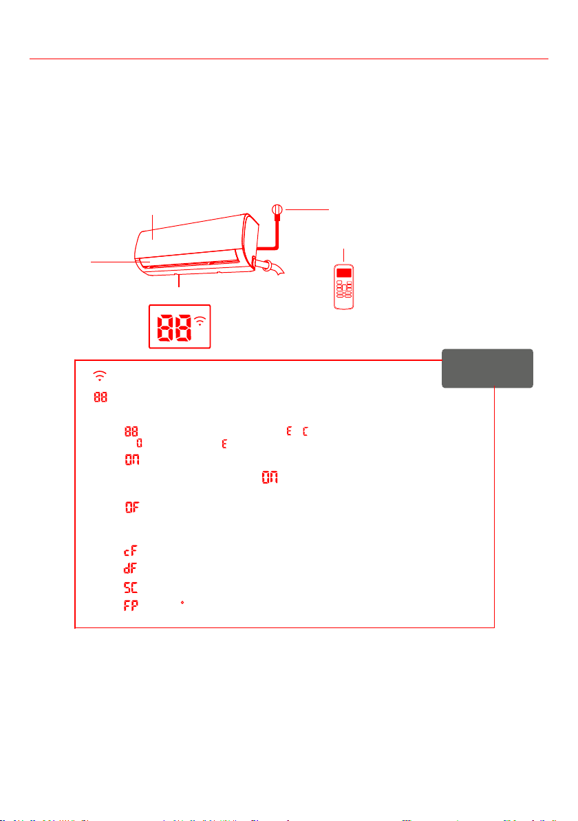
INDOOR UNIT DISPLAY
Note: Different models have different front panel and display window. Not all the indicators describing
below are available for the air conditioner you purchased. Check the indoor display window of the unit to
know which model you purchased.
Illustrations in this manual are for explanatory purposes. The actual shape of your indoor unit may be
slightly different. The actual shape shall prevail.
Power Cable (Not supplied)
Remote Control
Louver
Front Panel
Display window
Display Code
Meanings
Displays temperature, operation feature and
Error codes:
“ ” for 3 seconds when:
• FRESH, SWING, TURBO, or SILENCE feature is turned on
• TIMER OFF is set
• FRESH, SWING, TURBO, or SILENCE feature is turned off
“ ” when defrosting (cooling & heating units)
“ ” when anti-cold air feature is turned on
“ ” when unit is self-cleaning (some units)
,
,
“ ”
When ECO function (some units) is activated, the
illuminates gradually one by one as --
-- --set temperature -- ...... in one second interval.
“ ” when Wireless Control feature is activated (some units)
“ ” when 46 F heating feature is turned on (some units)
• TIMER ON is set (if the unit is OFF, remains on when TIMER ON is set )
“ ”
“ ” for 3 seconds when:
Operating Instructions
11
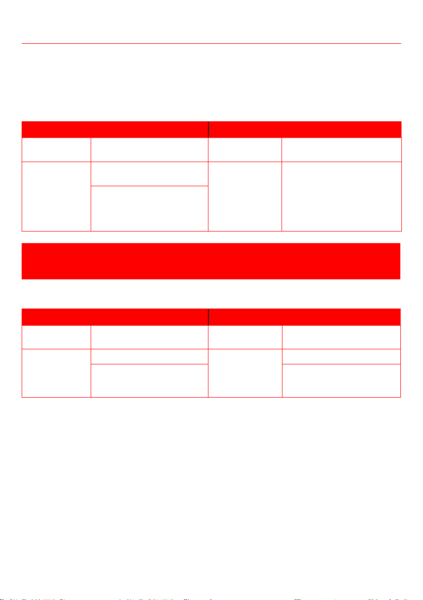
OPERATING TEMPERATURE
When your air conditioner is used outside of the following temperature ranges, certain safety protection
features may activate and cause the unit to disable.
Inverter Split Type
COOL MODE DRY MODE
Room
Temperature
17°C - 32°C
(62°F - 90°F)
0°C - 30°C
(32°F - 86°F)
10°C - 32°C
(50°F - 90°F)
Outdoor
Temperature
0°C - 50°C
(32°F - 122°F)
-15°C - 30°C
(5°F - 86°F)
0°C - 50°C
(32°F - 122°F)
-15°C - 50°C
(5°F - 122°F)
(For models with low temp.
cooling systems.)
When outside temperature is below 0°C (32°F), we strongly recommend keeping the unit plugged in at
all time to ensure smooth ongoing performance.
Fixed-speed Type
COOL MODE DRY MODE
Room
Temperature
17°C-32°C (62°F-90°F)
0°C-30°C
(32°F-86°F)
10°C-32°C (50°F-90°F)
Outdoor
Temperature
18°C-43°C (64°F-109°F)
-7°C-24°C
(19°F-75°F)
11°C-43°C (52°F-109°F)
-7°C-43°C (19°F-109°F)
(For models with low-temp
cooling systems)
18°C-43°C (64°F-109°F)
Note:
To further optimize the performance of your unit, follow below rules:
• Keep doors and windows closed.
• Limit energy usage by using TIMER ON and TIMER OFF functions.
• Do not block air inlets or outlets.
•
Operating Instructions
12
1. Auto-Restart
If the unit loses power, it will automatically restart with the prior settings once power has been
restored.
2. Anti-mildew
When turning off the unit from COOL, AUTO (COOL), or DRY mode, the air conditioner will continue
to operate at very low power to dry up condensed water to prevent mildew growth.
3. Louver Angle Memory
When turning on your unit, the louver will automatically resume its former angle.
4. Refrigerant Leakage Detection
when the unit detects any refrigerant leakage.
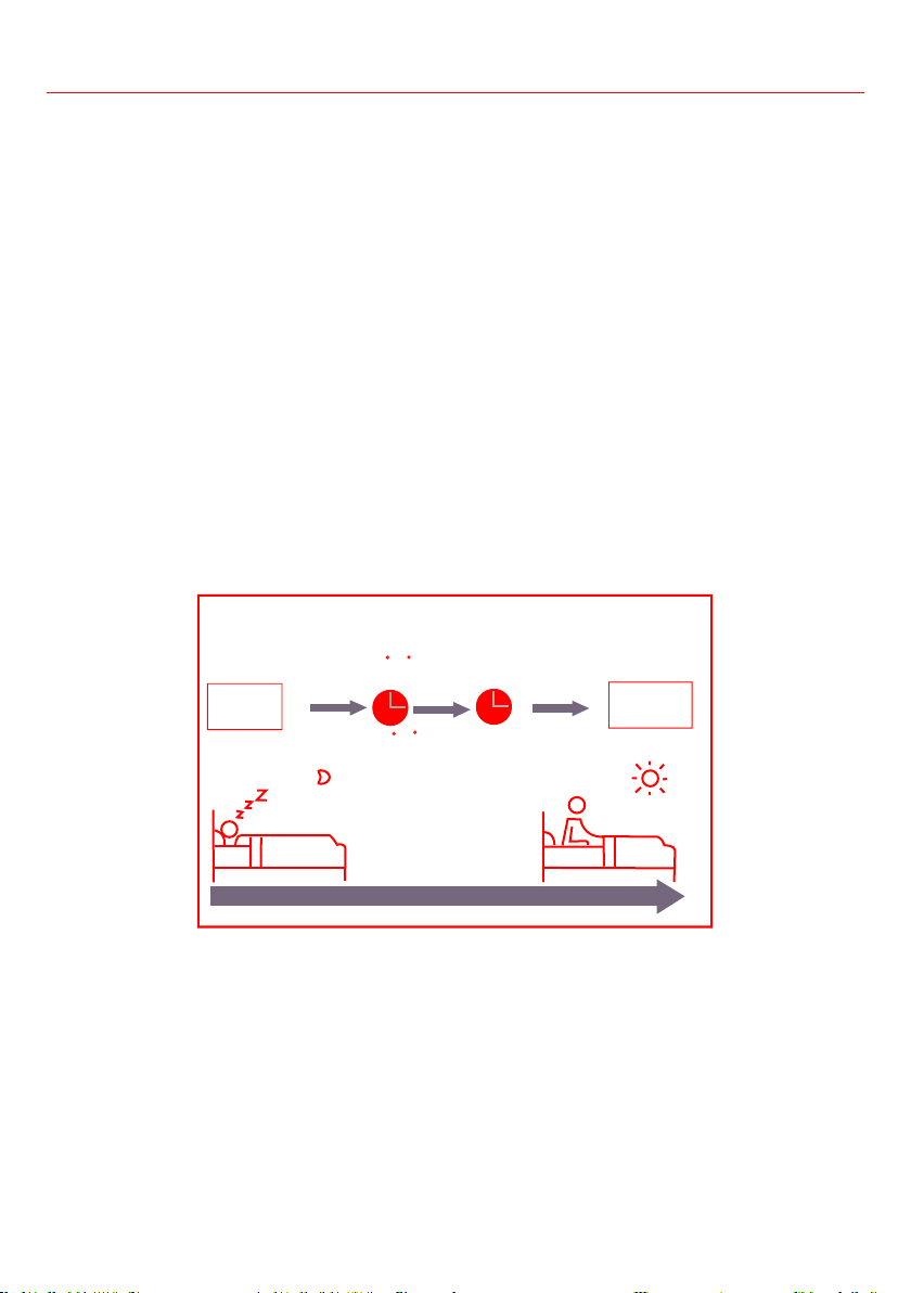
5. Sleep Operation
This function is used to decrease energy use while you sleep (and don’t need the same temperature
settings to stay comfortable). This function can only be activated via remote control and is not
available in FAN or DRY mode.
Press the SLEEP button when you are ready to go to sleep. When in COOL mode, the unit will
increase the temperature by 1°C (2°F) after 1 hour, and will increase an additional 1°C (2°F) after
another hour. When in HEAT mode, the unit will decrease the temperature by 1°C (2°F) after 1 hour,
and will decrease an additional 1°C (2°F) after another hour. The sleep feature will stop after 8 hours
Set
temperature
1hr
1hr
Keep
running
SLEEP Operation
Saving energy during sleep
Heat mode(-1 C/2 F) per hour
for the first two hours
Cool mode(+1 C/2 F) per hour
for the first two hours
6. Follow Me Operation
If you feel comfortable with the ambient temperature where you are, you can use the remote control to
send a signal to the air conditioner, which will be set to this temperature quickly.
• To activate this feature, press FOLLOW ME button, the remote control displays the ambient
temperature and send signal to the unit every 3 minutes.
• If the indoor unit doesn’t receive the signal for 7 minutes or pressing FOLLOW ME button again, the
Follow me function will terminate.
Operating Instructions
13
SETTING ANGLE OF AIR FLOW
While the unit is on, use the SWING/DIRECT button on remote control to set the direction (vertical angle)
Remote Control section for details.
Note:
When using COOL or DRY mode, do not set louver at a vertical an angle for long periods of time. This can
When using COOL or HEAT mode, setting the louver at a vertical an angle can reduce the performance of
remote control. Refer to Remote Control section for details.
Deflector rod
Operating Instructions
Fig.B
14
Operating Instructions
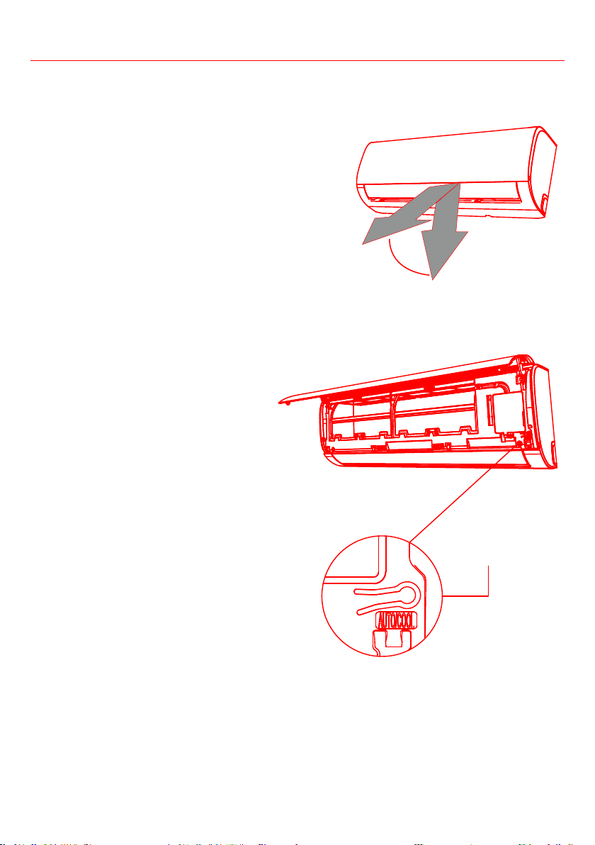
CAUTION
The manual button is intended for testing purposes and
emergency operation only. Do not use this function unless
the remote control is lost and it is absolutely necessary to
operate the unit. To restore to regular operation, use the
remote control to activate the unit. Turn off the unit before
any manual operation.
1. Open the front panel of the indoor unit.
2. Locate the MANUAL CONTROL button on the right-
hand side of the unit.
3. Press the MANUAL CONTROL button once to activate
FORCED AUTO mode.
4. Press the MANUAL CONTROL button again to activate
5. Press the MANUAL CONTROL button a
third time to turn the unit off.
6. Close the front panel.
Note: Do not move the louver by hand.
This will cause the louver to become out of
unit and unplug it for a few seconds, then
restart the unit. This will reset the louver.
CAUTION
and suction side of the unit. The high-speed
fan inside the unit may cause injury.
Range
Manual control
button
15
Operating Instructions
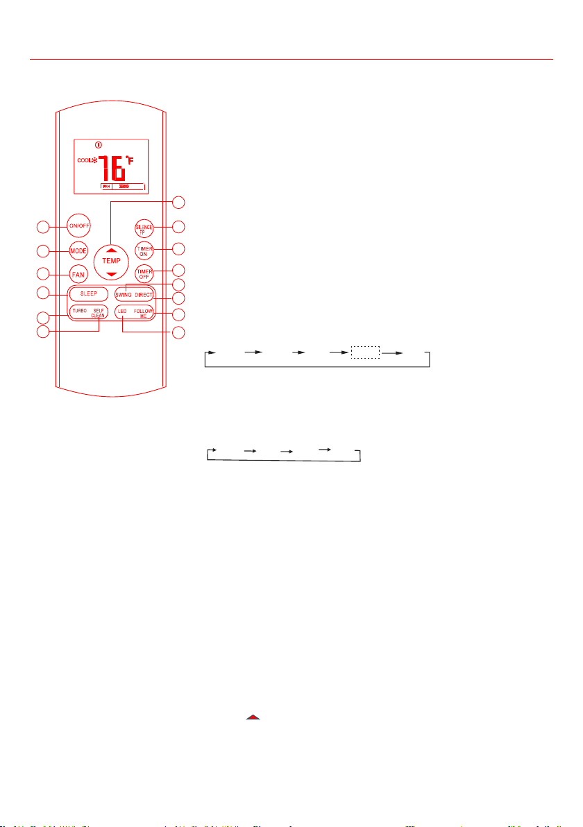
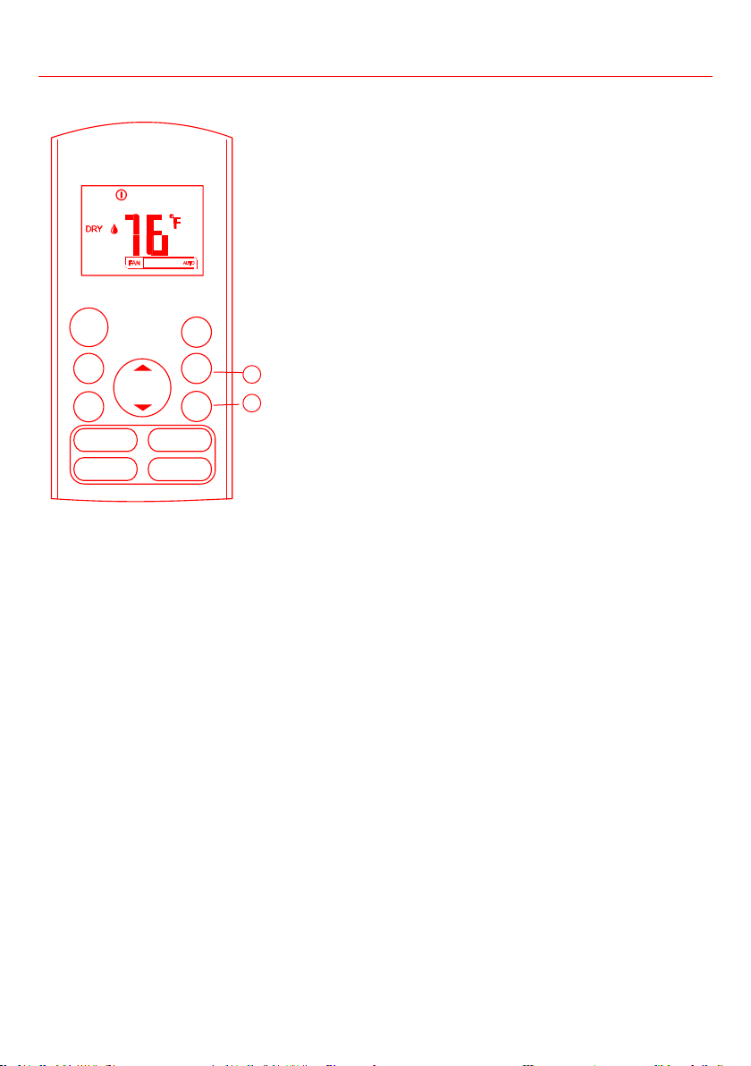
REMOTE CONTROL
Note:
• Buttons design is based on typical model and might be slightly
different from the actual one you purchased, the actual type shall
prevail.
• All the functions described are accomplished by the unit. If
the unit has not a feature, there is no corresponding operation
happens when pressing the relative button on the remote control.
• When there are wide differences between “Remote control
Illustration” and “USER’S MANUAL” on function description, the
description of “ USER’S MANUAL” shall prevail.
This button turns the air conditioner ON and OFF.
Press this button to switch the air conditioner mode in a sequence of
AUTO
COOL
DRY
HEAT FAN
Note: Do not select Heat mode if the machine you purchased is cooling-
only type. Heat mode is not supported by the cooling-only appliance.
Auto Low Med High
temperature and save energy. This function is available on COOL, HEAT
or AUTO mode only .
For details, see Sleep Operation in “Other Features” section on Page 12.
Note: Press MODE, FAN or ON/OFF button can exit the SLEEP mode.
reach the preset temperature at cooling or heating operation in the
shortest time (if the indoor unit does not support this function, there
is no corresponding operation happens when pressing this button.).
conditioner will automatically clean and dry the evaporator and keep it
as fresh for the next operation.
7. TEMP
Each time you push this button, the indoor temperature increases by
1°F. The highest temperature can be set is 86°F.
1
2
4
3
8
9
7
5
6
10
12
11
13
14
16
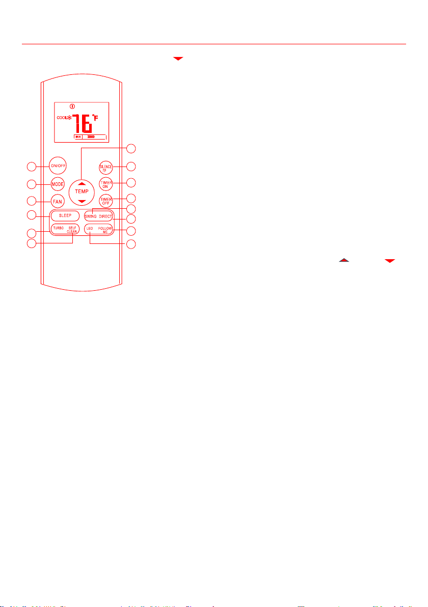
Operating Instructions
TEMP
Each time you push this button, the indoor temperature decreases by
1°F. The lowest temperature can be set is 62°F.
Note:
• Temperature control is not available in Fan mode.
• Press and hold both UP and DOWN buttons for 3 seconds to
switch between °C & °F temperature system.
• When the Silence function is activated, the unit will reduce the
noise to the lowest level and create a quiet and comfortable
room. Due to low frequency operation of compressor, it may result
SILENCE/FP
•
temperature of the air conditioner can be as lower as 46°F,
FP keeps the room temperature steady at 46°F and prevents
SILENCE/
FP button for more than 2 seconds. To exit FP function, press
ON/OFF, SLEEP, SILENCEFP, MODE, FAN, TEMP
or TEMP
button.
Press this button to initiate the auto-on time sequence. Each press
will increase the auto-timed setting in 30 minutes increments. When
the setting time displays 10.0, each press will increase the auto¬timed
setting 60 minutes increments. To cancel the auto-timed program,
simply adjust the auto-on time to 0.0.
Press this button to initiate the auto-off time sequence. Each press
will increase the auto-timed setting in 30 minutes increments. When
the setting time displays 10.0, each press will increase the auto-timed
setting 60 minutes increments. To cancel the auto-timed program,
simply adjust the auto-off time to 0.0
Press this button to activate the Follow Me feature, for details, refer to
Follow Me operation in “Other Features” section on Page 12.
Press to turn on or turn off the unit display.
1
2
4
3
8
9
7
5
6
10
12
11
13
14

17
Indicators on LCD
Mode display
AUTO
COOL DRY HEAT FAN
Displayed when remote controller is ON.
Battery display (low battery warning).
Displayed when TIMER ON time is set.
Displayed when TIMER OFF time is set.
Show set temperature or room temperature, or time
under TIMER setting.
Displayed in Sleep Mode operation.
Indicated that the air conditioner is operating in Follow
me mode.
Not available for this unit
Not available for this unit
Fan speed indications
Low speed
Medium speed
High speed
Auto fan speed
Note:
clear presentation. But during the actual operation only the
relative functional signs are shown on the display.
Operating Instructions
18
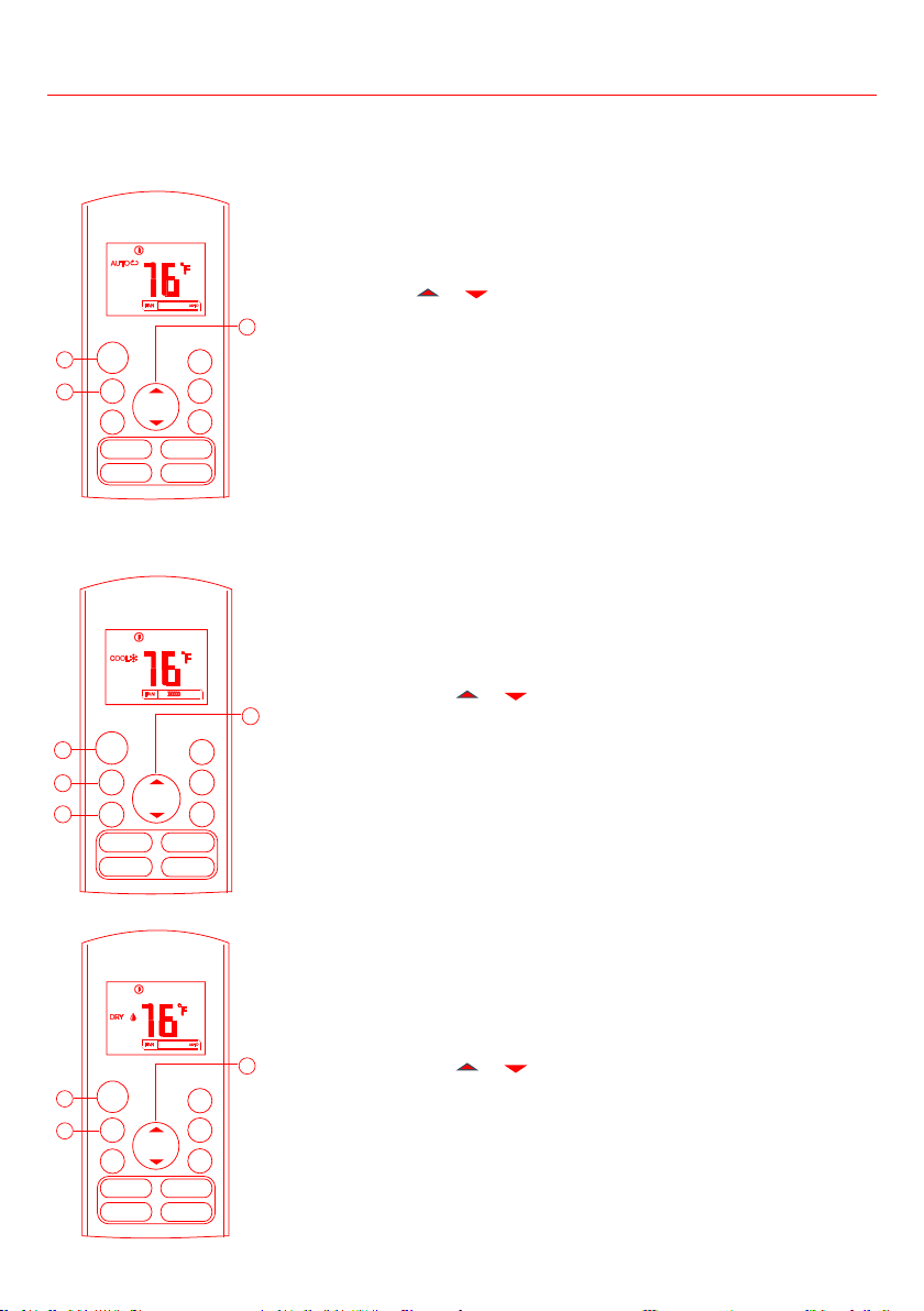
Auto operation
Ensure the unit is plugged in and power is available. The OPERATION
1. Press the MODE button and select Auto.
2. Press TEMP
or button to set the desired temperature. The
temperature can be set within a range of 62°F~86°F in 1°F increments.
3. Press the ON/OFF button to start the air conditioner.
Note:
- In Auto mode, the air conditioner can logically choose the mode of
Cooling, Fan, and Heating by sensing the difference between the actual
ambient room temperature and the set temperature.
- In Auto mode, you can not switch the fan speed. It has already been
automatically controlled.
- If Auto mode is not comfortable for you, select other mode as your
desire.
Ensure the unit is plugged in and power is available.
1. Press the MODE button to select COOL, HEAT (cooling & heating
models only) or FAN mode.
2. Press the TEMP
or buttons to set the desired temperature.
The temperature can be set within a range of 62°F~86°F in 1°F
increments.
3. Press the FAN
High.
4. Press the ON/OFF button to start the air conditioner.
Note:
In FAN mode, the setting temperature is not displayed on the remote
control and you can not control the room temperature either. In this case,
only step 1, 3 and 4 need to be performed.
Dehumidifying operation
Ensure the unit is plugged in and power is available. The OPERATION
1. Press the MODE button to select DRY mode.
2. Press the TEMP
or buttons to set the desired temperature.
The temperature can be set within a range of 62°F~86°F in 1 °F
increments.
3. Press the ON/OFF button to start the air conditioner.
Note:
In Dehumidifying mode, you can not switch fan speed. The fan speed is
automatically controlled.
Operating Instructions
SILENCE
FP
MODE
FAN
TEMP
ON/O FF
TIME R
ON
TIME R
OFF
3
1
2
LED FOL LOW
ME
TURB O SELF
CLE AN
SWIN G DIRE CT
SLEEP
MODE
FAN
TEMP
ON/O FF
SILENCE
FP
TIME R
ON
TIME R
OFF
3
1
2
LED FOL LOW
ME
TURB O SELF
CLE AN
SWING DIRECT
SLEEP
MODE
FAN
TEMP
ON/OFF
TIMER
ON
TIMER
OFF
4
1
3
2
SILENCE
FP
LED FOLLOW
ME
TURB O SELF
CLE AN
SWING DIRECT
SLEEP
19
Timer operation
Press the TIMER ON button to set the auto-on time of the unit.
Press the TIMER OFF button to set the auto-off time of the unit.
To set the Auto-on time.
1. Press the TIMER ON button. The remote control shows
TIMER ON, the last Auto-on setting time and the signal “H”
will be shown on the LCD display area. Now it is ready to
reset the Auto-on time to START the operation.
2. Press the TIMER ON button again to set desired Auto-on
time. Each time you press the button, the time increases
by half an hour between 0 and 10 hours and by one hour
between 10 and 24 hours.
3. After setting the TIMER ON. There will be a one second delay
before the remote control transmits the signal to the air
conditioner. Then, after approximately another 2 seconds, the
signal “h” will disappear and the set temperature will resume
on the LCD display.
To set the Auto-off time.
1. Press the TIMER OFF button. The remote control shows
TIMER OFF, the last Auto-off setting time and the signal “H”
will be shown on the LCD display area. Now it is ready to
reset the Auto-off time to stop the operation.
2. Press the TIMER OFF button again to set desired Auto-off
time. Each time you press the button, the time increases
by half an hour between 0 and 10 hours and by one hour
between 10 and 24 hours.
3. After setting the TIMER OFF. There will be a one second
delay before the remote control transmits the signal to the
air conditioner. Then, after approximately another 2 seconds,
the signal “H “ will disappear and the set temperature will
resume on the LCD display.
CAUTION
• When you select the timer operation, the remote control
automatically transmits the timer signal to the indoor unit
a location where it can transmit the signal to the indoor unit
properly.
• The effective operation time set by the remote control for
1.5, 2.0, 2.5, 3.0, 3.5, 4.0, 4.5, 5.0, 5.5, 6.0, 6.5, 7.0, 7.5, 8.0, 8.5,
9.0, 9.5, 10, 11, 12, 13, 14, 15, 16, 17, 18, 19, 20, 21, 22, 23 and 24
hours.
Operating Instructions
2
1
MODE
FAN
TEMP
ON/OFF
TIMER
ON
TIMER
OFF
SILENCE
FP
LED FOLLOW
ME
TURBO SELF
CLEAN
SWING DIRECT
SLEEP
20
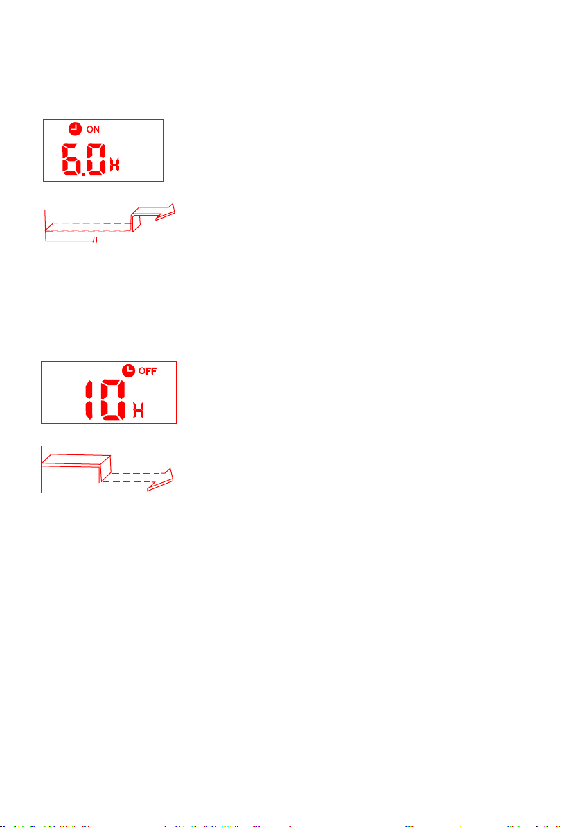
TIMER ON (Auto-on Operation)
The TIMER ON feature is useful when you want the unit to turn
on automatically before you return home. The air conditioner will
automatically start operating at the set time.
Example:
To start the air conditioner in 6 hours.
1. Press TIMER ON button, the last set auto-on time and a “h” will
show on the display area.
2. Press TIMER ON button repeatedly until “6.0h” is displayed on the
TIMER ON display of the remote control.
3. Wait for 3 seconds and the digital display area will show the
temperature again. The “TIMER ON” indicator remains on and this
function is activated.
TIMER OFF (Auto-off Operation)
The TIMER OFF feature is useful when you want the unit to turn
off automatically after you go to bed. The air conditioner will stop
automatically at the set time.
Example:
To stop the air conditioner in 10 hours.
1. Press TIMER OFF button, the last set auto-off time and a “h” will
show on the display area.
2. Press TIMER OFF button repeatedly until “10h” is displayed on the
TIMER OFF display of the remote control.
3. Wait for 3 seconds and the digital display area will show the
temperature again. The “TIMER OFF” indicator remains on and this
function is activated.
Operating Instructions
Start
Off
6 hours later
Set
Stop
On
Set 10 hours later
21
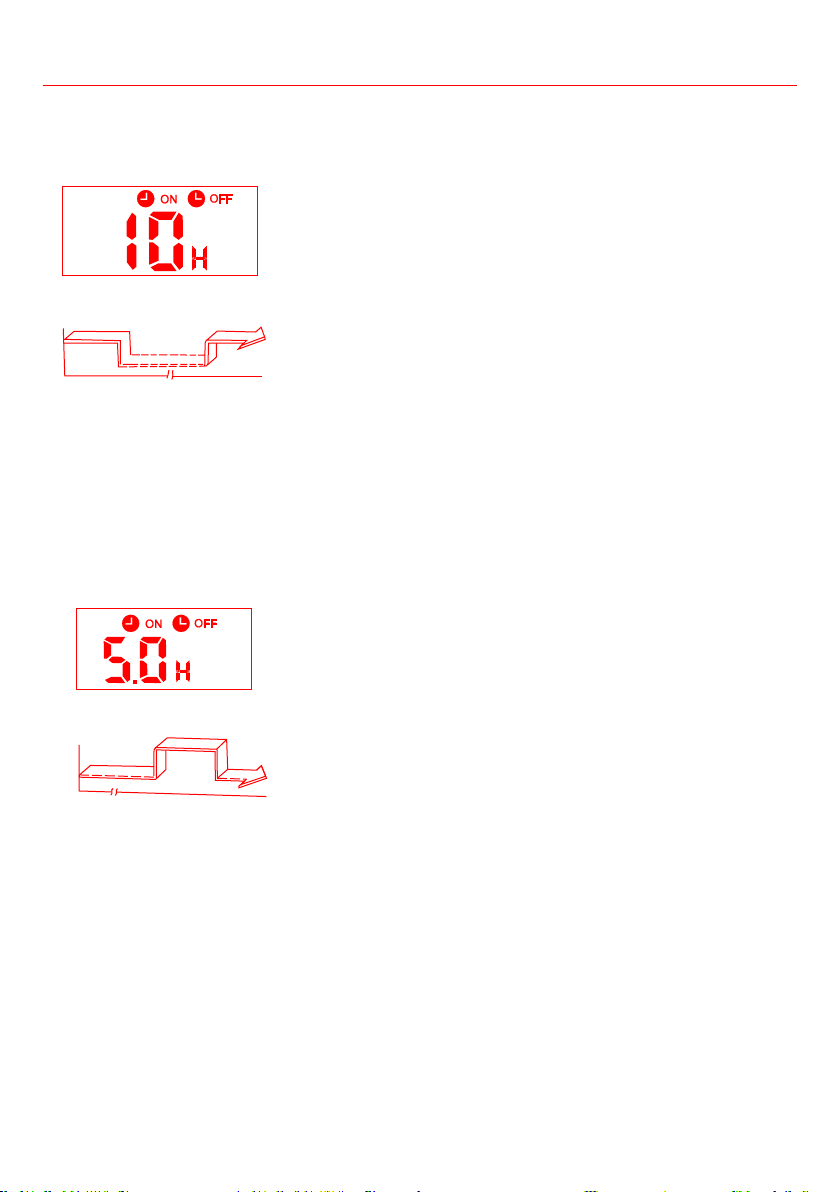
simultaneously)
• TIMER OFF - TIMER ON
(On — Stop — Start operation)
This feature is useful when you want to stop the air conditioner
after you go to bed, and start it again in the morning when you
wake up or when you return home.
Example:
To stop the air conditioner 2 hours after setting and start it again
10 hours after setting.
1. Press the TIMER OFF button.
2. Press the TIMER OFF button repeatedly until “2.0H” is
displayed on the TIMER OFF display.
3. Press the TIMER ON button.
4. Press the TIMER ON button repeatedly until “10H” is displayed
on the TIMER ON display .
5. Wait for 3 seconds and the digital display area will show the
temperature again. The “TIMER ON OFF” indicator remains on and
this function is activated.
• TIMER ON - TIMER OFF
(Off — Start — Stop operation)
This feature is useful when you want to start the air conditioner
before you wake up and stop it after you leave the house.
Example:
To start the air conditioner 2 hours after setting, and stop it 5
hours after setting.
1. Press TIMER ON button.
2. Press TIMER ON button repeatedly until “2.0H” is displayed on
the TIMER ON display.
3. Press TIMER OFF button.
4. Press TIMER OFF button repeatedly until “5.0H” is displayed on
the TIMER OFF display .
5. Wait for 3 seconds and the digital display area will show the
temperature again. The “TIMER ON OFF” indicator remains on and
this function is activated.
Operating Instructions
On
Stop
2 hours later
after setting
Set
Start
10 hours later
after setting
Off
Stop
Start
2 hours later
after setting
5 hours later
after setting
Set
22
Operating Instructions
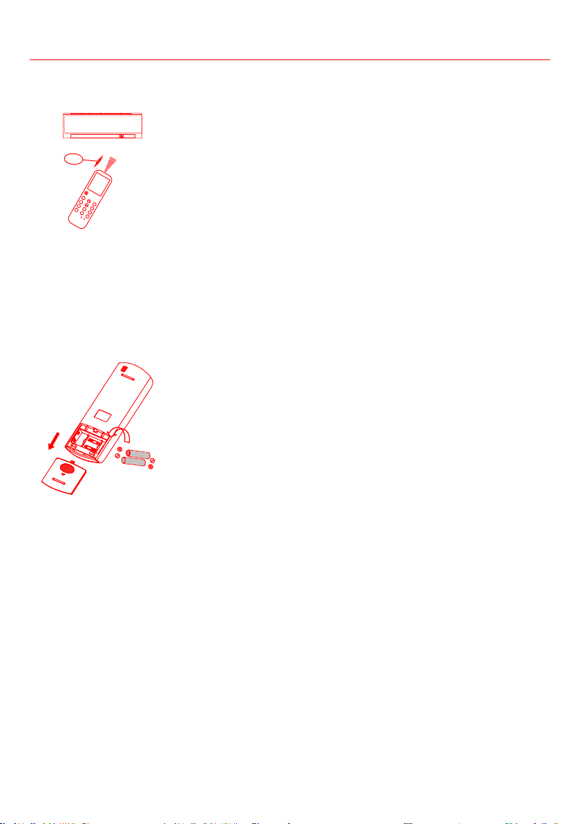
Location of the remote control
• Use the remote control within a distance of 26ft from the appliance,
pointing it towards the receiver of the appliance. Reception is
CAUTION
• The air conditioner will not operate if curtains, doors or other
materials block the signals from the remote control to the indoor unit.
• Prevent any liquid from falling into the remote control. Do not expose
the remote control to direct sunlight or heat.
• If the infrared signal receiver on the indoor unit is exposed to direct
sunlight, the air conditioner may not function properly. Use curtains to
prevent the sunlight from falling on the receiver.
• If other electrical appliances react to the remote control, either move
these appliances or consult your local dealer.
• Do not drop the remote control. Handle with care.
• Do not place heavy objects on the remote control, or step on it.
The following cases signify exhausted batteries. Replace old batteries with
new ones.
• Receiving beep is not emitted when a signal is transmitted.
• The power indicator fades away.
in the back rear part and protected by a cover.
(1) Remove the cover in the rear part of the remote control.
(2) Remove the old batteries and insert the new batteries, placing the (+)
and (-) ends correctly.
(3) Install the cover back on.
Note:
When the batteries are removed, the remote control erases all programming.
After inserting new batteries, the remote control must be reprogrammed.
CAUTION
• Do not mix old and new batteries or batteries of different types.
• Do not leave the batteries in the remote control if they are not going
to be used for 2 or 3 months.
• Do not dispose batteries as unsorted municipal waste. It is necessary to
collect such waste separately for special treatment.
26ft
MO DE
SW I
NG
TEM P
SHO RT CU T
FAN
SPE ED
TIMER
OFF
RESE T LOCK
LED
FOL LOW M E
TIMER
ON
TUR BO
SEL F CLEA N
DIREC T
SLE EP
FRE SH
23
Cleaning and Maintenance
CLEANING YOUR INDOOR UNIT
WARNING - BEFORE CLEANING OR MAINTENANCE
Always turn off your air conditioner system and disconnect its power supply before cleaning or
maintenance.
CAUTION
Only use a soft and dry cloth to wipe the unit clean. If the unit is very dirty, you can use a cloth soaked in
warm water to wipe it clean.
• Do not use chemicals or chemically treated cloths to clean the unit.
•
cause the plastic surface to crack or deform.
• Do not use water hotter than 40°C (104°F) to clean the front panel. This can deform and discolor the panel.
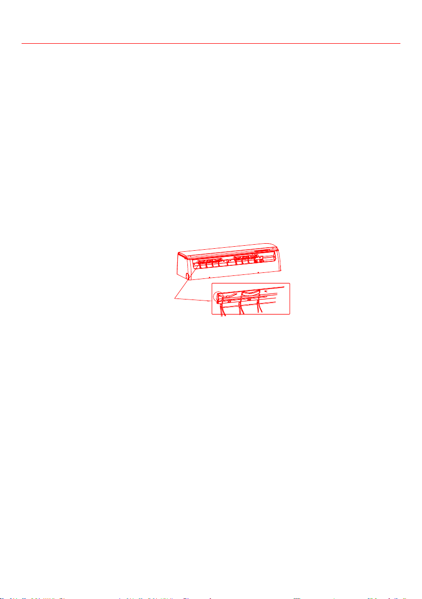
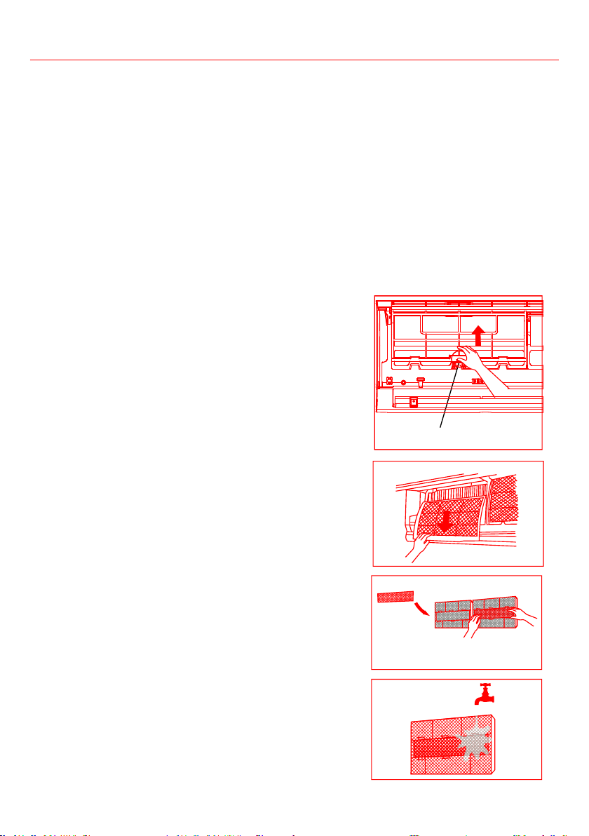
CLEANING YOUR AIR FILTER
every two weeks.
1. Lift the front panel of the indoor unit.
2.
lift it up, then pull it towards yourself.
3.
4.
5.
use mild detergent.
6.
7.
direct sunlight.
8.
it into the indoor unit.
9. Close the front panel of the indoor unit.
CAUTION
minutes after turning off the unit.
CAUTION
•
•
unit. The sharp metal edges can hurt you.
• Do not use water to clean the inside of the indoor unit. This
can cause electrical shock.
•
Remove air freshening filter (Not supplied)
from back of the larger filter
Filter Tab
24
Cleaning and Maintenance
Air Filter Cleaning Reminder
To reset the reminder, press the LED button on your remote control for 4 times, or press the MANUAL
CONTROL
restart the unit.
Air Filter Replacement Reminder
To reset the reminder, press the LED button on your remote control for 4 times, or press the MANUAL
CONTROL
restart the unit.
CAUTION
•
licensed service provider.
•
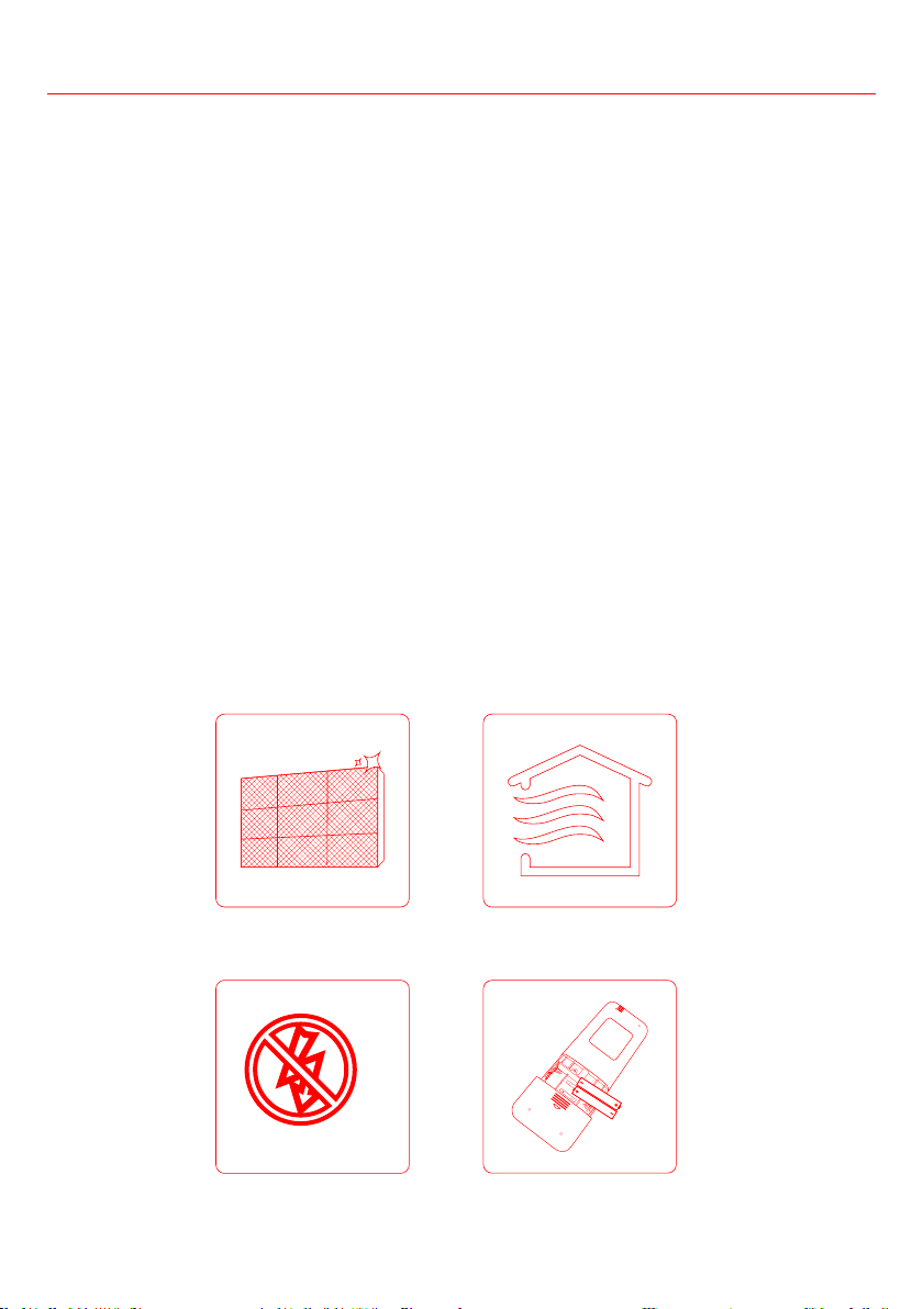
Clean all filters
Turn on FAN function until
unit dries out completely
Turn off the unit and
disconnect the power
Remove batteries
from remote control
25
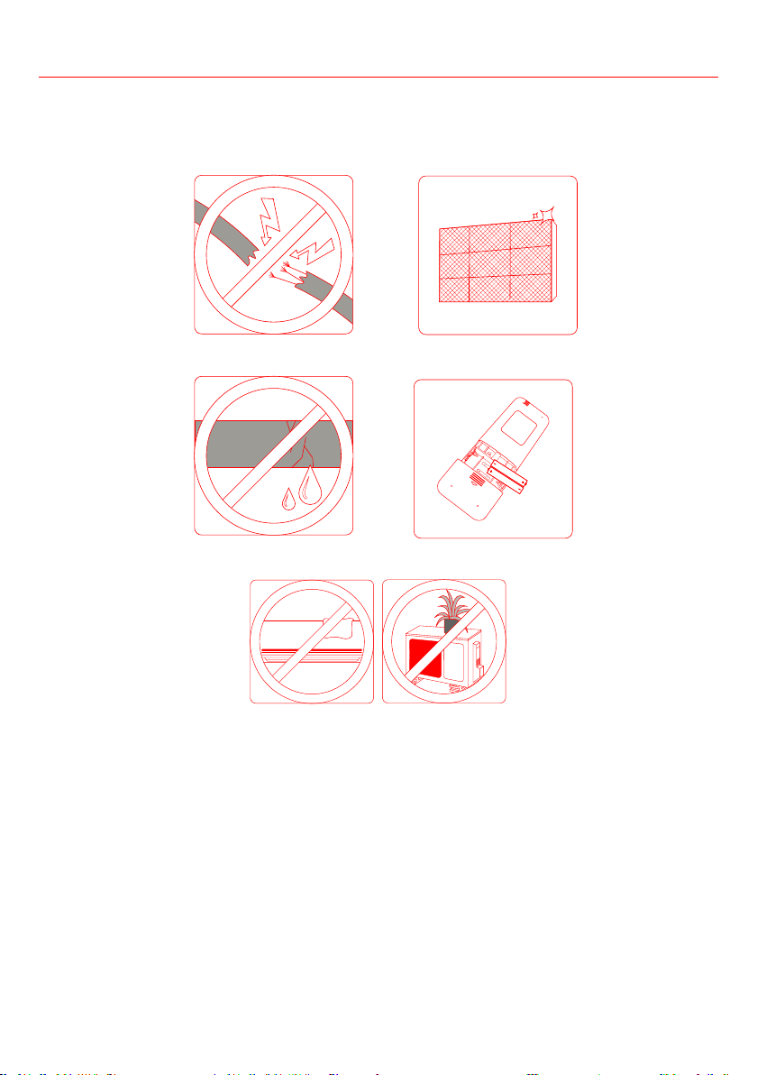
Check for damaged wires Clean all filters
Check for leaks Replace batteries
Make sure nothing is blocking air inlets and outlets
SAFETY PRECAUTIONS
If ANY of the following conditions occurs, turn off your unit immediately!
• The power cord is damaged or abnormally warm.
• You smell a burning odor.
• The unit emits loud or abnormal sounds.
• A power fuse blows or the circuit breaker frequently shuts down.
• Water or other objects fall into or out of the unit.
CAUTION
Cleaning and Maintenance
26
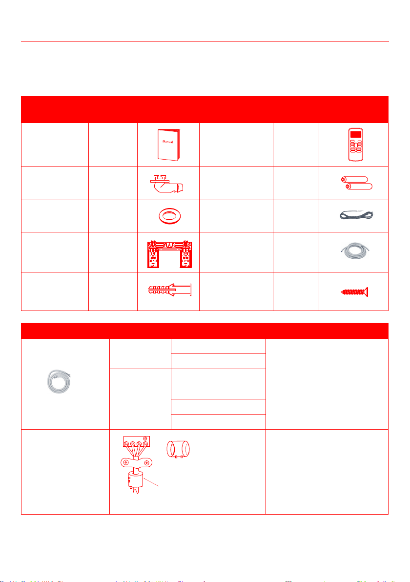
The air conditioning system comes with the following accessories. Use all of the installation parts and
accessories to install the air conditioner. Improper installation may result in water leakage, electrical shock
The items not included with the air conditioner must be purchased separately.
Name of
Accessories
Q‘ty(pc) Shape
Name of
Accessories
Q‘ty(pc) Shape
Manual 2~3 Remote controller 1
Drain joint
(for cooling &
heating models)
1 Battery 2
Seal
(for cooling &
heating models)
1
5m connection
wire
1
Mounting plate 1 5m drain pipe 1
Anchor
5-8
(depending
on models)
Mounting plate
5-8
(depending
on models)
Name Shape Quantity(PC)
Connecting pipe
assembly
Liquid side Φ
1
Φ
Φ
Φ
Φ
Φ
Magnetic ring and belt
(Not supplied. You
must purchase them
separately. Consult
the dealer about the
unit you purchased).
Pass the belt through the
hole of the Magnetic ring to
the wiring diagram to install
it on the connective cable. )
1
Accessories
1 2 3
27
Installation
The Split AC contains both Indoor (Part 1) and Outdoor (Part 2) units, these main unit parts are shipped
separately in two boxes. Start installation only once you have received both part boxes. It is recommended
to have the Split AC professionally installed by HVAC specialist.
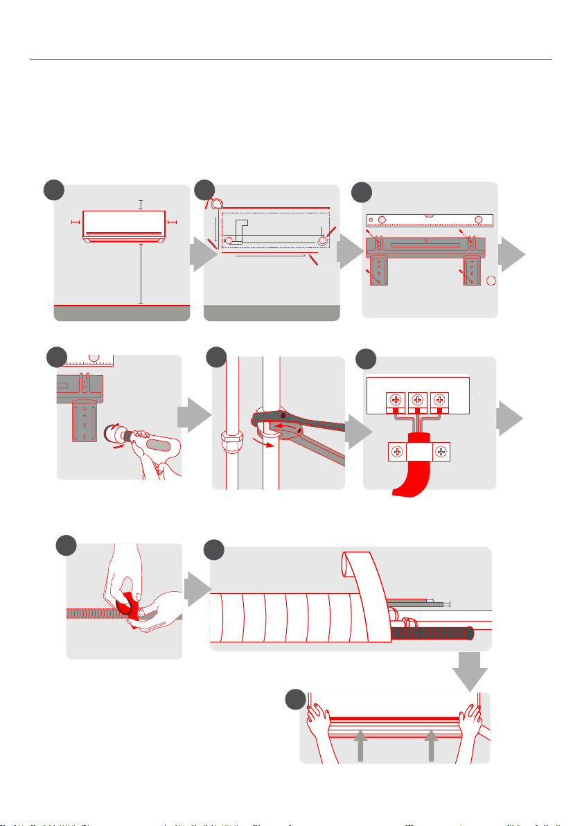
Select Installation Location
Attach Mounting Plate
Determine Wall Hole Position
1 2
3
Drill Wall Hole
4
12cm
(4.75in)
2.3m (90.55in)
12cm
(4.75in)
15cm (5.9in)
Mount Indoor Unit
STEP
8
Wrap Piping and Cable
(not applicable for some locations in the US )
Connect Piping
Prepare Drain Hose
Connect Wiring
(not applicable for some
locations in the US )
4 5
6
7
8
9
28
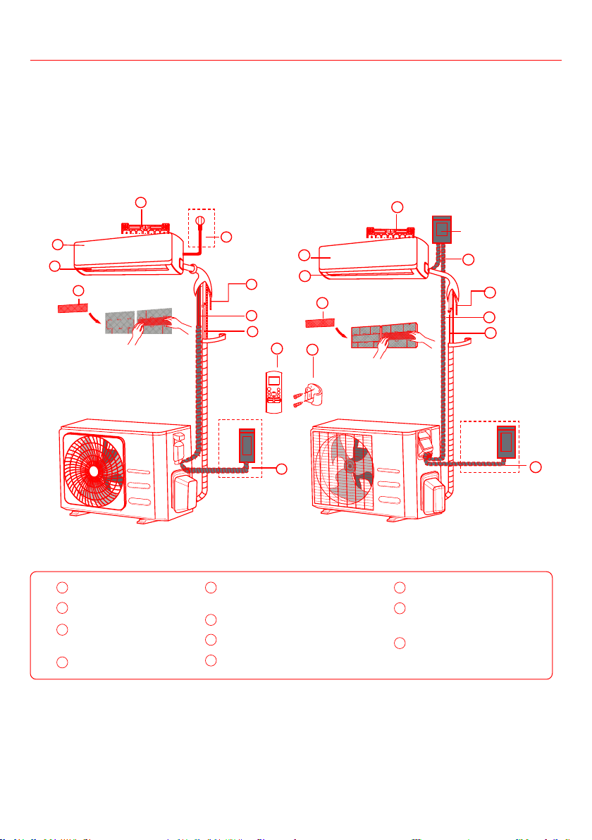
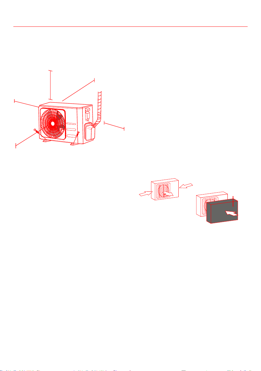
UNIT PARTS
Note:
• The installation must be performed in accordance with the requirements of local and national
standards.
• The installation may be slightly different in different areas.
(1) (2)
1
2
3
4
6
7
8
9
10
11
Air-break switch
3
1
2
4
5
6
7
8
11
5
Installation
Wall Mounting Plate
Front Panel
Power Cable
(Not supplied)
Louver
Functional Filter (On Back of
Main Filter - Not supplied)
Drainage Pipe
Signal Cable
Refrigerant Piping
Remote Controller
Remote controller
Holder (Not supplied)
Outdoor Unit Power
Cable (Not supplied)
Note: Illustrations in this manual are for explanatory purposes. The actual shape of your indoor unit may
be slightly different. The actual shape shall prevail.
5
6
7
8
9
10
11
3
4
1
2
29
Installation
INDOOR UNIT INSTALLATION
PRIOR TO INSTALLATION
Before installing the indoor unit, refer to the label
on the product box to make sure that the model
number of the indoor unit matches the model
number of the outdoor unit.
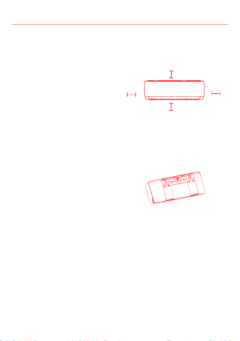
Step 1: Select installation location
Before installing the indoor unit, you must
choose an appropriate location. The following are
standards that will help you choose an appropriate
location for the unit.
Proper installation locations meet the following
standards:
•
• Convenient drainage
Noise from the unit will not disturb other
people
• Firm and solid—the location will not vibrate
• Strong enough to support the weight of the unit
• A location at least one meter from all other
electrical devices (e.g., TV, radio, computer)
DO NOT install unit in the following locations:
• Near any source of heat, steam, or combustible
gas
•
clothing
• Near any obstacle that might block air
circulation
• Near the doorway
• In a location subject to direct sunlight
While choosing a location, be aware that you
should leave ample room for a wall hole (see
Drill wall hole for connective piping step) for the
signal cable and refrigerant piping that connect
the indoor and outdoor units. The default position
for all piping is the right side of the indoor unit
(while facing the unit). However, the unit can
accommodate piping to both the left and right.
Refer to the following diagram to ensure proper
4.75in
or more
90.55in or more
4.75in
or more
5.9in or more
The mounting plate is the device on which you will
mount the indoor unit.
• Take out the mounting plate at the back of the
indoor unit.
• Secure the mounting plate to the wall with
the screws provided. Make sure that mounting
Note: If the wall is made of brick, concrete, or
similar material, drill 0.2in-diameter holes in the
wall and insert the sleeve anchors provided. Then
secure the mounting plate to the wall by tightening
the screws directly into the clip anchors.
30
Installation
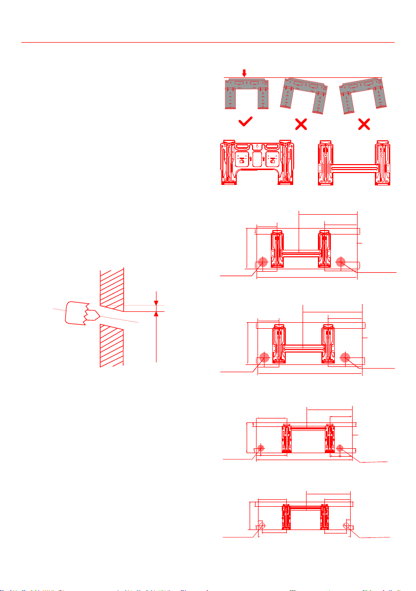
Step 3: Drill wall hole for connective piping
1. Determine the location of the wall hole based
on the position of the mounting plate. Refer to
the Mounting Plate Dimensions.
2. Use a 2.5 inches or 3.54 inches (depending on
models ) core drill to drill a hole in the wall.
Make sure that the hole is drilled at a slight
downward angle, so that the outdoor end of
the hole is lower than the indoor end by about
0.2 to 0.275 inches. This will ensure proper
water drainage.
3. Place the
protective wall cuffprotective wall cuff in the hole. This
protects the edges of the hole and will help
CAUTION
When drilling the wall hole, make sure to avoid
wires, plumbing, and other sensitive components.
Wall
Indoor Outdoor
0.2-0.275in
MOUNTING PLATE DIMENSIONS
Different models have different mounting plates.
the shape of the mounting plate may be slightly
different. But the installation dimensions are the
Note: When the gas side connective pipe is
Φ
Correct orientation of Mounting Plate
Type A
Type B
Left rear wall
hole 2.5in
Right rear wall
hole 2.5in
Indoor unit
outline
1.5in
1.5in
11.2in
1.85in
1.85in
Model A
5.8in
1.7in
4.1in
28in
4.2in
5.1in
9.3in
15.8in
Model B
9.1in
9.7in
7.3in
5.5in
31.7in
16.2in
Left rear wall
hole 2.5in
Right rear wall
hole 2.5in
Indoor unit
outline
1.5in
1.5in
11.2in
1.85in
1.85in
1.7in
4.2in
Left rear wall
hole 2.5in
Right rear wall
hole 2.5in
Indoor unit
outline
11.88in
1.4in
1.4in
1.85in
1.85in
Model C
11.2in
9.57in
1.7in
9.5in
5.6in
3.9in
37.7in
18in
Model D
Left rear wall
hole 2.5in
Right rear wall
hole 2.5in
12.79in
2.16in
1.85in
1.85in
2.16in
10.4in
40.85in
8.6in
13.5in
11.8in
1.77in
1.77in
22in
31
Step 4: Prepare the refrigerant piping
The refrigerant piping is inside an insulating sleeve
attached to the back of the unit. You must prepare
the piping before passing it through the hole in the
wall.
1. Based on the position of the wall hole relative
to the mounting plate, choose the side from
which the piping will exit the unit.
2. If the wall hole is behind the unit, keep the
knock-out panel in place. If the wall hole is
to the side of the indoor unit, remove the
plastic knock-out panel from that side of the
unit. This will create a slot through which your
piping can exit the unit. Use needle nose pliers
by hand.
Knock-out Panel
3. If existing connective piping is already
embedded in the wall, proceed directly to
the step. If there is no
embedded piping, connect the indoor unit’s
refrigerant piping to the connective piping that
will join the indoor and outdoor units. Refer to
the Refrigerant Piping Connection section of
this manual for detailed instructions.
NOTE ON PIPING ANGLE
Refrigerant piping can exit the indoor unit from four
left rear and right rear.
CAUTION
Be extremely careful not to dent or damage the
piping while bending them away from the unit.
Any dents in the piping will affect the unit’s
performance.
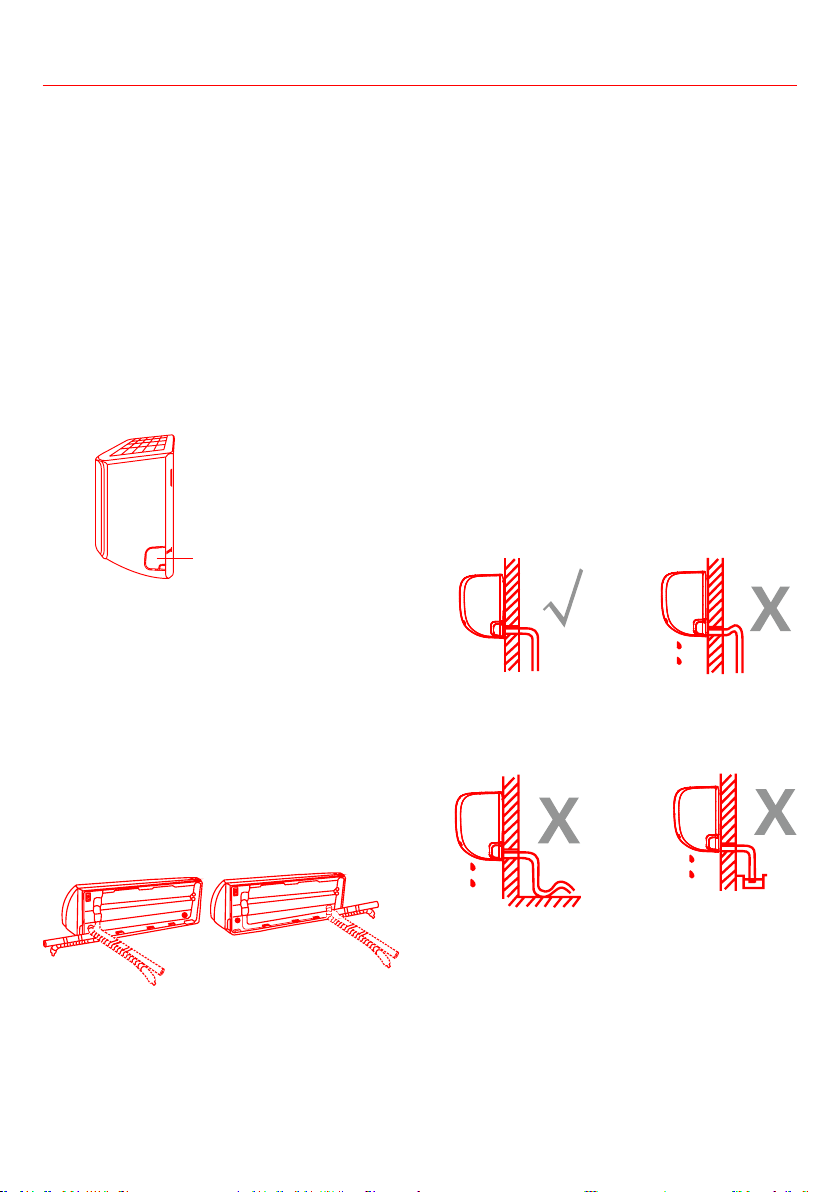
Step 5: Connect the drain hose
By default, the drain hose is attached to the left-
hand side of unit (when you’re facing the back
of the unit). However, it can also be attached to
the right-hand side. To ensure proper drainage,
attach the drain hose on the same side that your
refrigerant piping exits the unit. Attach drain hose
extension (purchased separately) to the end of
drain hose.
•
tape to ensure a good seal and to prevent leaks.
• For the portion of the drain hose that will
remain indoors, wrap it with foam pipe
insulation to prevent condensation.
•
of water into the drain pan to make sure that
Make sure to arrange the drain hose according to
Installation
CORRECT
Make sure there are no
kinks or dent in drain hose
to ensure proper drainage.
NOT CORRECT
Kinks in the drain
hose will create
water traps.
NOT CORRECT
Kinks in the drain
hose will create
water traps.
NOT CORRECT
Do not place the
end of the drain
hose in water or
in containers that
collect water. This
will prevent proper
drainage.
32
To prevent unwanted leaks you
must plug the unused drain hole
with the rubber plug provided.
BEFORE PERFORMING ANY ELECTRICAL WORK,
1. All wiring must comply with local & national
electrical codes and regulations and must be
installed by a licensed electrician.
2. All electrical connections must be made
according to the Electrical Connection Diagram
located on the panels of the indoor and
outdoor units.
3. If there is a serious safety issue with the
power supply, stop work immediately. Explain
your reasoning to the client, and refuse to
install the unit until the safety issue is properly
resolved.
4.
5.
surge protector and main power switch with a
capacity of 1.5 times the maximum current of
the unit.
6.
or circuit breaker that disconnects all poles
circuit breaker or switch.
7. Only connect the unit to an individual branch
circuit outlet. Do not connect another
appliance to that outlet.
8. Make sure to properly ground the air
conditioner.
9.
wiring can cause the terminal to overheat,
resulting in product malfunction and possible
10. Do not let wires touch or rest against
refrigerant tubing, compressor, or any moving
parts within the unit.
11. If the unit has an auxiliary electric heater, it
must be installed at least 40 inches away from
any combustible materials.
12. To avoid getting an electric shock, never touch
the electrical components soon after the
power supply has been turned off. After turning
off the power, always wait 10 minutes or more
before you touch the electrical components.
WARNING
WORK, TURN OFF THE MAIN POWER TO THE
SYSTEM.
Step 6: Connect the signal cable
The signal cable enables communication between
the indoor and outdoor units. You must choose the
Cable Types
•
H05V2V2-F
•
•
Minimum Cross-Sectional Area of Power and Signal
Cables (For reference)
Rated Current of
Appliance (A)
Nominal Cross-
Sectional Area (mm²)
0.75
1
1.5
2.5
4
6
Installation
33
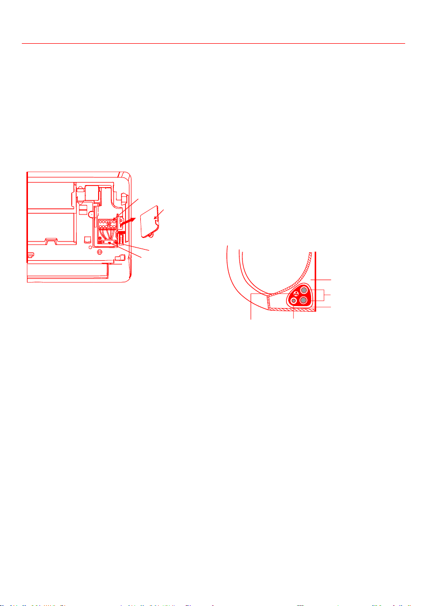
Choose the right cable size
fuse, and switch needed is determined by the
maximum current of the unit. The maximum
current is indicated on the nameplate located on
the side panel of the unit. Refer to this nameplate
to choose the right cable, fuse, or switch.
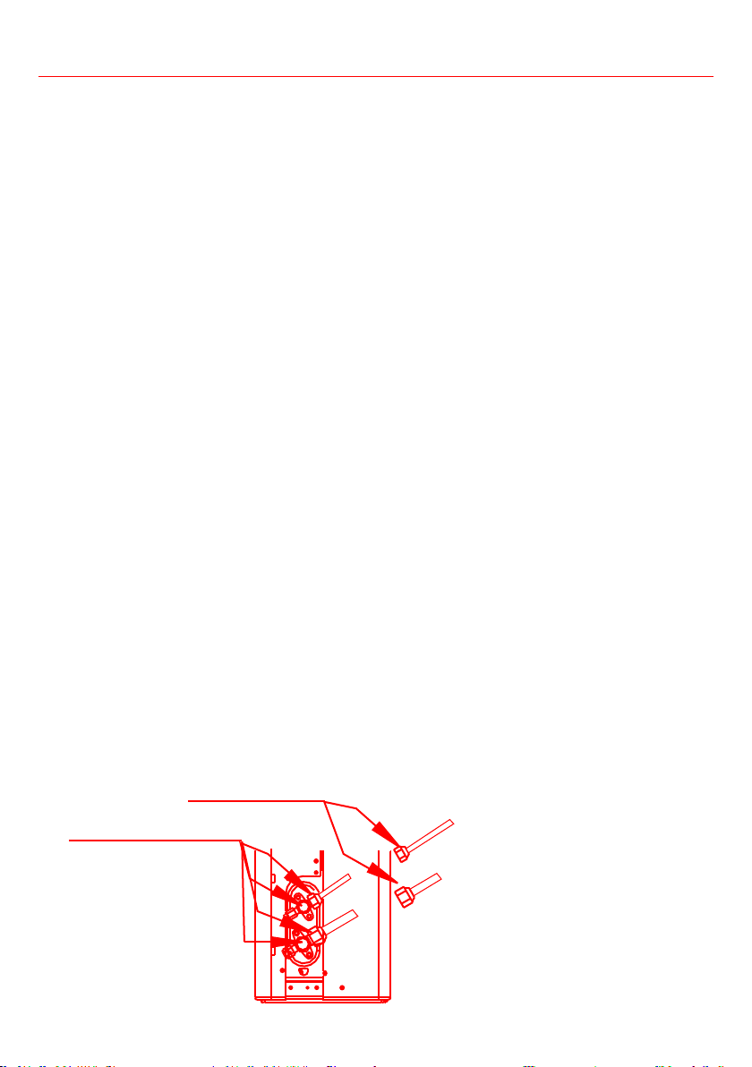
1. Open the front panel of the indoor unit.
2. Using a screwdriver to open the wire box cover
on the right side of the unit. This will reveal
the terminal block.
Terminal block
Wire cover
Screw
Cable clamp
WARNING
LOCATED ON THE BACK OF THE INDOOR UNIT’S
FRONT PANEL.
3. Unscrew the cable clamp below the terminal
block and place it to the side.
4. Facing the back of the unit, remove the plastic
panel on the bottom left-hand side.
5. Feed the signal wire through the slot, from the
back of the unit to the front.
6. Facing the front of the unit, connect the wire
according to the indoor unit’s wiring diagram,
to its corresponding terminal.
CAUTION
dangerous, and can cause the air conditioning unit
to malfunction.
7. After checking to make sure every connection
is secure, use the cable clamp to fasten the
signal cable to the unit. Screw the cable clamp
down tightly.
8. Replace the wire cover on the front of the unit
and the plastic panel on the back.
NOTE ABOUT WIRING
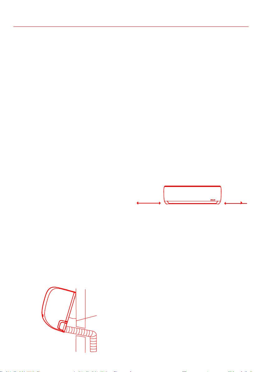
Step 7: Wrap piping and cables
Before passing the piping, drain hose, and the
signal cable through the wall hole, you must bundle
them together to save space, to protect them and
insulate them (Not applicable in North America).
1. Bundle the drain hose, refrigerant pipes, and
Indoor Unit
Space behind unit
Refrigerant piping
Drain hose
Signal wire
Insulation tape
Make sure that the drain hose is at the bottom of
the bundle. Putting the drain hose at the top of the
WIRES
While bundling these items together, do not
intertwine or cross the signal cable with any other
wiring.
2. Use adhesive vinyl tape to attach the drain
hose to the underside of the refrigerant pipes.
3. Use insulation tape to wrap the signal wire,
refrigerant pipes, and drain hose tightly
together. Double-check that all items are
bundled.
Installation
34
Installation
DO NOT WRAP ENDS OF PIPING
When wrapping the bundle, keep the ends of the
piping unwrapped. You need to access them to
test for leaks at the end of the installation process
(refer to Electrical Checks and Leak Checks section
of this manual).
Step 8: Mount indoor unit
If you install new connective piping to the outdoor
unit, take the following steps:
1. If you have already passed the refrigerant
piping through the hole in the wall, proceed to
below Step 4.
2. Otherwise, double-check that the ends of the
refrigerant pipes are sealed to prevent dirt or
foreign materials from entering the pipes.
3. Slowly pass the wrapped bundle of refrigerant
pipes, drain hose, and signal wire through the
hole in the wall.
4. Hook the top of the indoor unit on the upper
hook of the mounting plate.
5.
plate by applying slight pressure to the left
and right-hand sides of the unit. The unit
should not jiggle or shift.
6. Using even pressure, push down on the
bottom half of the unit. Keep pushing down
until the unit snaps onto the hooks along the
bottom of the mounting plate.
7.
by applying slight pressure to the left and the
right-hand sides of the unit.
If the refrigerant piping is already embedded in the
wall, take the following steps:
1. Hook the top of the indoor unit on the upper
hook of the mounting plate.
2. Use a bracket or wedge to prop up the unit,
giving you enough room to connect the
refrigerant piping, signal cable, and drain hose.
Wedge
30°
3. Connect drain hose and refrigerant piping
(refer to Refrigerant Piping Connection section
of this manual for instructions).
4. Keep pipe connection point exposed to
perform the leak test (refer to Electrical
Checks and Leak Checks section of this
manual).
5. After the leak test, wrap the connection point
with insulation tape.
6. Remove the bracket or wedge that is propping
up the unit.
7. Using even pressure, push down on the
bottom half of the unit. Keep pushing down
until the unit snaps onto the hooks along the
bottom of the mounting plate.
UNIT IS ADJUSTABLE
Keep in mind that the hooks on the mounting
plate are smaller than the holes on the back of
the unit. If you don’t have ample room to connect
embedded pipes to the indoor unit, the unit can be
adjusted left or right by about 1.25-1.95in depending
on the model.
Move to left or right
1.2-1.95in
1.2-1.95in
35
OUTDOOR UNIT INSTALLATION
Install the unit by following local codes and
regulations. There may be slightly differences
between different regions.
evoba
ni42
24in on right
12in on left
79in in front
12in from back wall
Step 1: Select installation location
Before installing the outdoor unit, you must
choose an appropriate location. The following are
standards that will help you choose an appropriate
location for the unit.
Proper installation locations meet the following
standards:
• Meets all spatial requirements shown in
Installation Space Requirements above.
•
• Firm and solid—the location can support the
unit and will not vibrate
• Noise from the unit will not disturb others
• Protected from prolonged periods of direct
sunlight or rain
• Where snowfall is anticipated, raise the unit
above the base pad to prevent ice buildup and
coil damage. Mount the unit high enough to be
above the average accumulated area snowfall.
The minimum height must be 18 inches.
DO NOT install unit in the following locations:
• Near an obstacle that will block air inlets and
outlets
• Near a public street, crowded areas, or where
noise from the unit will disturb others
• Near animals or plants that will be harmed by
hot air discharge
• Near any source of combustible gas
• In a location that is exposed to large amounts
of dust
• In a location exposed to a excessive amounts
of salty air
•
Install unit so that air outlet fan is at a 90° angle
to the direction of the wind. If needed, build
a barrier in front of the unit to protect it from
extremely heavy winds. See Figures below.
Strong
wind
Strong wind
Strong wind
Wind Baffle
• If the unit is frequently exposed to heavy rain
Build a shelter above the unit to protect it from
the rain or snow. Be careful not to obstruct the
• If the unit is frequently exposed to salty air
Use outdoor unit that is specially designed to
resist corrosion.
Installation
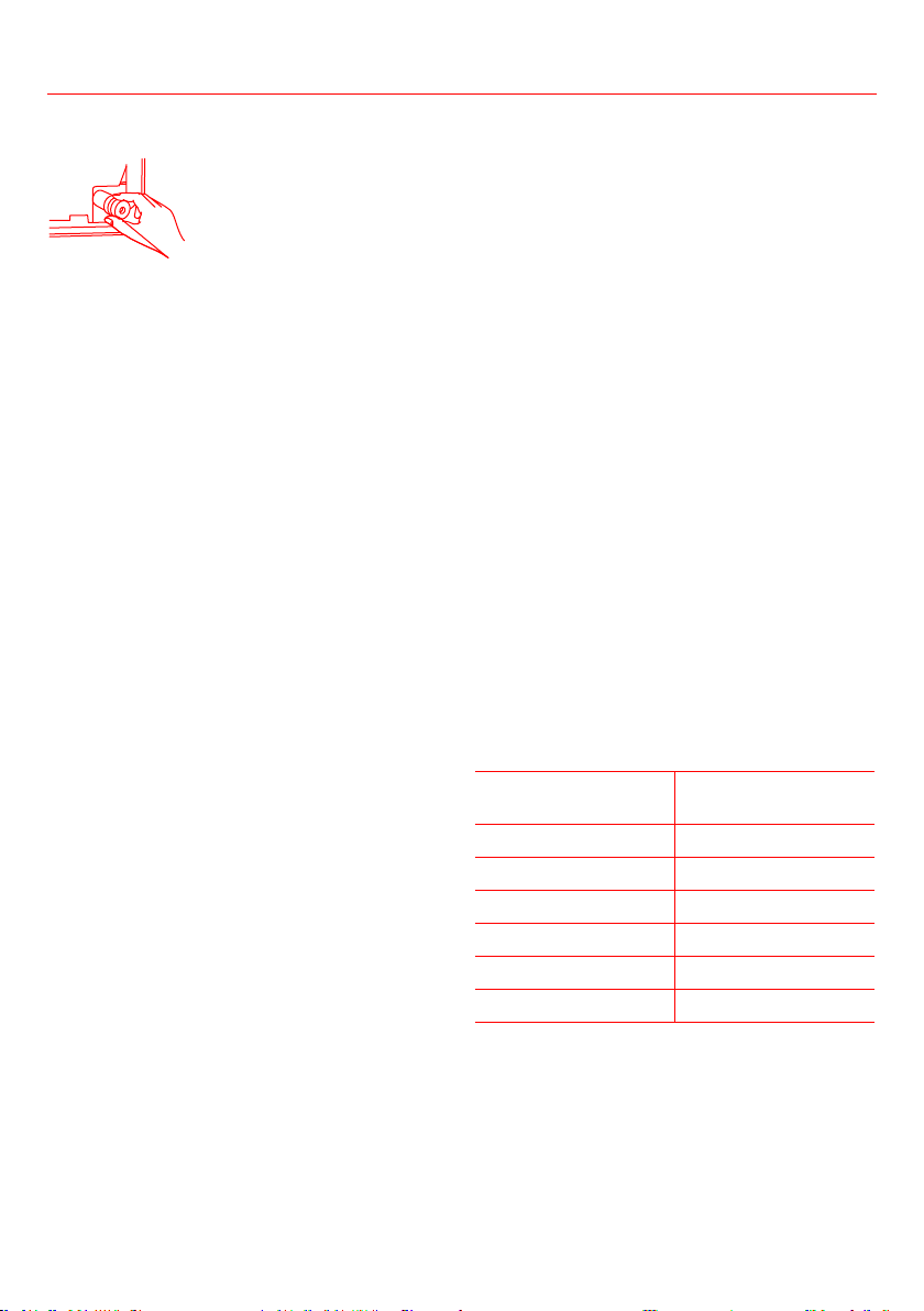
36
unit only)
Before bolting the outdoor unit in place, you must
install the drain joint at the bottom of the unit.
Note that there are two different types of drain
joints depending on the type of outdoor unit.
If the drain joint comes with a rubber seal (see
1. Fit the rubber seal on the end of the drain
joint that will connect to the outdoor unit.
2. Insert the drain joint into the hole in the base
pan of the unit.
3. Rotate the drain joint 90° until it clicks in
place facing the front of the unit.
4. Connect a drain hose extension (not included)
to the drain joint to redirect water from the
unit during heating mode.
If the drain joint doesn’t come with a rubber seal
(see Fig. B
1. Insert the drain joint into the hole in the base
pan of the unit. The drain joint will click in
place.
2. Connect a drain hose extension (not included)
to the drain joint to redirect water from the
unit during heating mode.
Seal
Drain joint
(A) (B)
Base pan hole of
outdoor unit
Seal
IN COLD CLIMATES
In cold climates, make sure that the drain hose
is as vertical as possible to ensure swift water
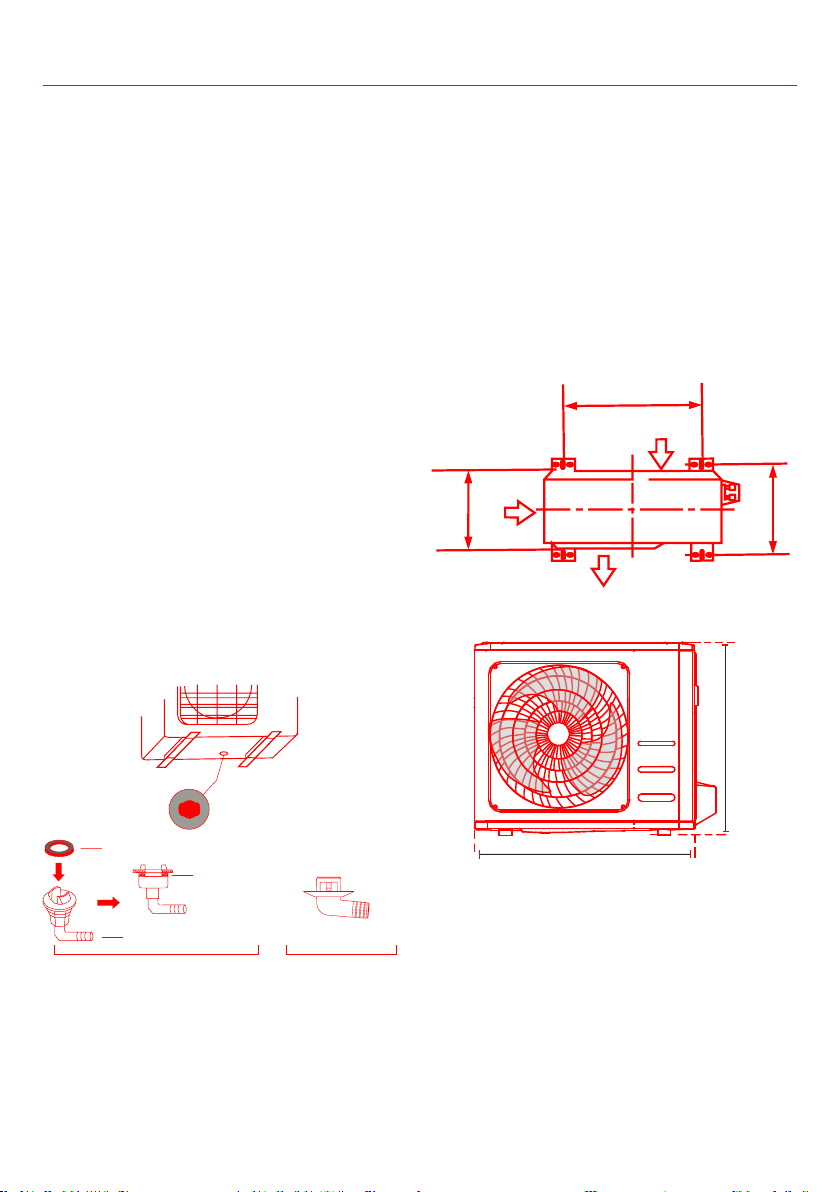
Step 3: Anchor outdoor unit
The outdoor unit can be anchored to the ground or
to a wall-mounted bracket with bolt (M10). Prepare
the installation base of the unit according to the
dimensions below.
UNIT MOUNTING DIMENSIONS
and the distance between their mounting feet.
Prepare the installation base of the unit according
to the dimensions below.
A
B
D
Air inlet
Air inlet
Air inlet
W
H
Installation
37
If you install the unit on the ground or on
a concrete mounting platform, take the
following steps:
1. Mark the positions for four expansion
bolts based on the dimensions chart.
2. Pre-drill holes for expansion bolts.
3. Place a nut on the end of each expansion
bolt.
4. Hammer expansion bolts into the pre-
drilled holes.
5. Remove the nuts from expansion bolts,
and place outdoor unit on bolts.
6. Put washer on each expansion bolt, then
replace the nuts.
7. Use a wrench to tighten each nut until
snug.
WARNING
PROTECTION IS RECOMMENDED AT ALL TIMES.
If you install the unit on a wall-mounted
bracket, take the following steps:
CAUTION
Make sure that the wall is made of solid brick,
concrete, or of similarly strong material. The
wall must be able to support at least four
times the weight of the unit.
1. Mark the positions for the bracket holes
based on the dimensions chart.
2. Pre-drill the holes for the expansion bolts.
3. Place a washer and nut on the end of each
expansion bolt.
4. Thread expansion bolts through holes
in mounting brackets, put the mounting
brackets on the wall, and then hammer
the expansion bolts into the wall.
5. Check that the mounting brackets are
level.
6. Carefully lift the unit and place its
mounting feet on the brackets.
7.
8. If allowed, install the unit with rubber
gaskets to reduce vibrations and noise.
Installation
Outdoor Unit Dimensions (mm)
Mounting Dimensions
Distance A (mm) Distance B (mm)
681x434x285 (26.8”x17.1”x11.2”) 460 (18.1”) 292 (11.5”)
700x550x270 (27.5”x21.6”x10.6”) 450 (17.7”) 260 (10.2”)
700x550x275 (27.5”x21.6”x10.8”) 450 (17.7”) 260 (10.2”)
720x495x270 (28.3”x19.5”x10.6”) 452 (17.7”) 255 (10.0”)
728x555x300 (28.7”x21.8”x11.8”) 452 (17.8”) 302(11.9”)
765x555x303 (30.1”x21.8”x11.9”) 452 (17.8”) 286(11.3”)
770x555x300 (30.3”x21.8”x11.8”) 487 (19.2”) 298 (11.7”)
805x554x330 (31.7”x21.8”x12.9”) 511 (20.1”) 317 (12.5”)
800x554x333 (31.5”x21.8”x13.1”) 514 (20.2”) 340 (13.4”)
845x702x363 (33.3”x27.6”x14.3”) 540 (21.3”) 350 (13.8”)
890x673x342 (35.0”x26.5”x13.5”) 663 (26.1”) 354 (13.9”)
946x810x420 (37.2”x31.9”x16.5”) 673 (26.5”) 403 (15.9”)
946x810x410 (37.2”x31.9”x16.1”)
673 (26.5”)
403 (15.9”)
38
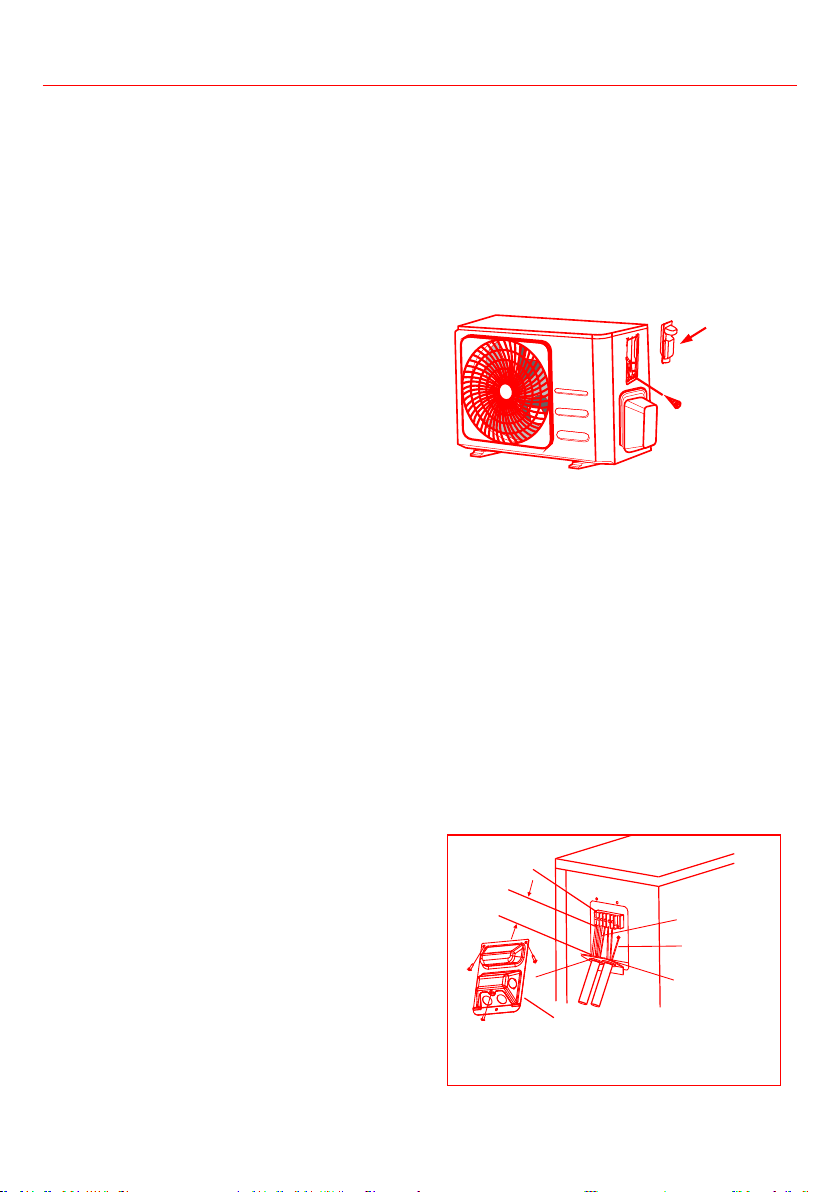
Step 4: Connect signal and power cables
The outdoor unit’s terminal block is protected by
an electrical wiring cover on the side of the unit.
A comprehensive wiring diagram is printed on the
inside of the wiring cover.
WARNING
WORK, TURN OFF THE MAIN POWER TO THE
SYSTEM.
1.
•
H05V2V2-F
•
•
fuse, and switch needed is determined by the
maximum current of the unit. The maximum
current is indicated on the nameplate located on
the side panel of the unit. Refer to the nameplate
to choose the right cable, fuse, or switch.
a. Using wire strippers, strip the rubber jacket
from both ends of the cable to reveal about
1.57in of the wires inside.
b. Strip the insulation from the ends of the wires.
c. Using a wire crimper, crimp u-lugs on the ends
of the wires.
PAY ATTENTION TO LIVE WIRE
While crimping wires, make sure you clearly
distinguish the Live (“L”) Wire from other wires.
WARNING
LOCATED INSIDE OF WIRE COVER OF THE
OUTDOOR UNIT.
2. Unscrew the electrical wiring cover and
remove it.
3. Unscrew the cable clamp below the terminal
block and place it to the side.
4. Connect the wire according to the wiring
wire to its corresponding terminal.
5. After checking to make sure every connection
is secure, loop the wires around to prevent
6. Using the cable clamp, fasten the cable to the
unit. Screw the cable clamp down tightly.
7. Insulate unused wires with PVC electrical tape.
Arrange them so that they do not touch any
electrical or metal parts.
8. Replace the wire cover on the side of the unit,
and screw it in place.
Cover
Screw
In North America
1. Remove the wire cover from the unit by
loosening the 3 screws.
2. Remove the caps on the conduit panel.
3. Temporarily mount the conduit tubes (not
included) on the conduit panel.
4. Properly connect both the power supply
and low voltage lines to the corresponding
terminals on the terminal block.
5.
codes.
6.
inches longer than the required length for
wiring.
7. Use lock nuts to secure the conduit tubes.
G
Wire Cover
Over 1.57in.(40mm)
Terminal block
Conduit panel
Connecting cable
Power supply cord
Please select the appropriate through-hole according
to the diameter of the wire.
Installation
39
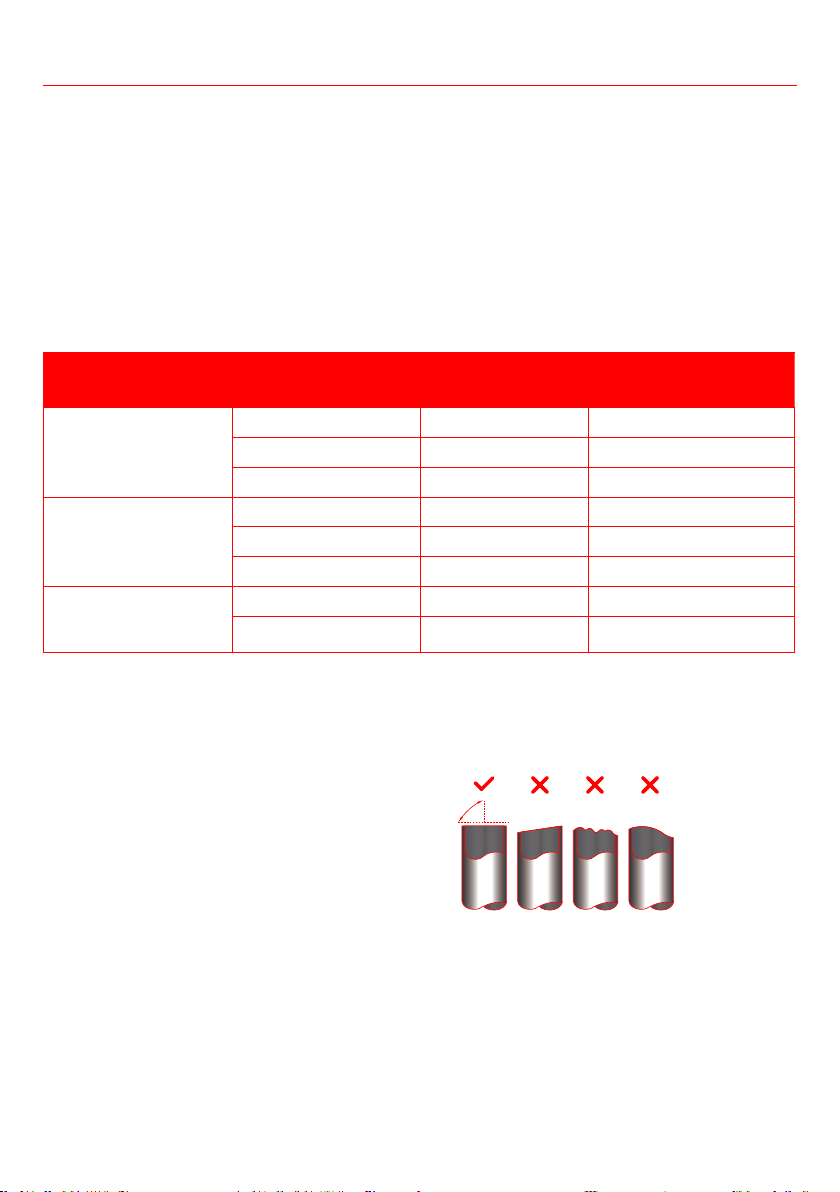
Step 1: Cut pipes
When preparing refrigerant pipes, take extra care
future maintenance.
1. Mea sure the distance between the indoor and
outdoor units.
2. Using a pipe cutter, cut the pipe a little longer
than the measured distance.
3. Make sure that the pipe is cut at a perfect 90°
angle.
Oblique Rough Warped
90°
Be extra careful not to damage, dent, or deform the
pipe while cutting. This will drastically reduce the
Refrigerant Piping Connection
enter the unit. The presence of other gases or substances will lower the unit’s capacity, and can cause
abnormally high pressure in the refrigeration cycle. This can cause explosion and injury.
Note on Pipe Length
MODEL
R410A,R32 Inverter
Split Air Conditioner
25 (82ft) 10 (33ft)
30 (98.5ft) 20 (66ft)
50 (164ft) 25 (82ft)
R22 Fixed-speed
Split Air Conditioner
10 (33ft) 5 (16ft)
15 (49ft) 8(26ft)
20 (66ft) 10(33ft)
R410A, R32 Fixed-
speed Split Air
Conditioner
20 (66ft) 8(26ft)
25 (82ft) 10(33ft)
40
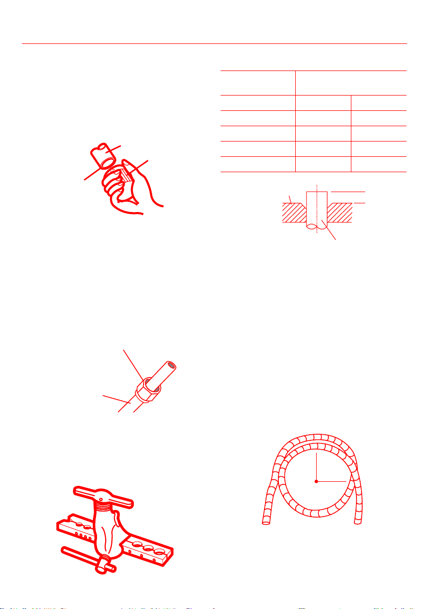
Step 2: Remove burrs
Burrs can affect the air-tight seal of refrigerant piping
connection. They must be completely removed.
1. Hold the pipe at a downward angle to prevent
burrs from falling into the pipe.
2. Using a reamer or deburring tool, remove all
burrs from the cut section of the pipe.
Pipe
Reamer
Point down
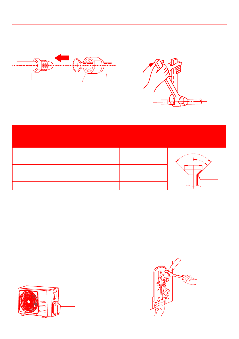
Step 3: Flare pipe ends
1. After removing burrs from cut pipe, seal
the ends with PVC tape to prevent foreign
materials from entering the pipe.
2. Sheath the pipe with insulating material.
3.
sure they are facing in the right direction,
because you can’t put them on or change their
Flare nut
Copper pipe
4. Remove PVC tape from ends of pipe when
5.
The end of the pipe must extend beyond the
dimensions shown in the table below.
Outer Diameter
of Pipe (mm)
A (mm)
Min. Max.
Ø6.35 (Ø 0.25”) 0.7 (0.0275”) 1.3 (0.05”)
Ø9.52 (Ø 0.375”) 1.0 (0.04”) 1.6 (0.063”)
Ø12.7 (Ø 0.5”) 1.0 (0.04”) 1.8 (0.07”)
Ø16 (Ø 0.63”) 2.0 (0.078”) 2.2 (0.086”)
Ø19 (Ø 0.75”) 2.0 (0.078”) 2.4 (0.094”)
Flare form
Pipe
A
6.
7.
8.
inspect the end of the pipe for cracks and
Step 4: Connect pipes
When connecting refrigerant pipes, be careful not
to use excessive torque or to deform the piping in
pipe, then the high-pressure pipe.
MINIMUM BEND RADIUS
When bending connective refrigerant piping, the
minimum bending radius is 4 inches.
4in
Radius
Refrigerant Piping Connection
41
Instructions for Connecting Piping to Indoor Unit
1. Align the center of the two pipes that you will
connect.
Indoor unit tubing Flare nut Pipe
2.
hand.
3. Using a spanner, grip the nut on the unit tubing.
4.
tubing, use a torque wrench to tighten the
Torque Requirements table below. Loosen the
Refrigerant Piping Connection
TORQUE REQUIREMENTS
OUTER DIAMETER
OF PIPE
TORQUE
FLARE DIMEN
Ø6.35 (Ø 0.25”) 18~20(180~200kgf.cm) 8.4~8.7 (0.33~0.34”)
R0.4~0. 8
45
°
±
2
90
°
±
4
B
Ø9.52 (Ø 0.375”) 32~39(320~390kgf.cm) 13.2~13.5 (0.52~0.53”)
Ø12.7 (Ø 0.5”) 49~59(490~590kgf.cm) 13.2~13.5 (0.52~0.53”)
Ø16 (Ø 0.63”) 57~71(570~710kgf.cm) 19.2~19.7 (0.76~0.78”)
Ø19 ( Ø 0.75”) 67~101(670~1010kgf.cm) 23.2~23.7 (0.91~0.93”)
Excessive force can break the nut or damage the
refrigerant piping. You must not exceed torque
requirements shown in the table above.
Instructions for Connecting Piping to Outdoor
Unit
1. Unscrew the cover from the packed valve on
the side of the outdoor unit.
2. Remove protective caps from ends of valves.
3.
4. Using a spanner, grip the body of the valve. Do
not grip the nut that seals the service valve.
Valve cover
5.
according to the correct torque values.
6.
again.
7. Repeat Steps 3 to 6 for the remaining pipe.
USE SPANNER TO GRIP MAIN BODY OF VALVE
other parts of valve.
42
Air Evacuation
Preparations and Precautions
Air and foreign matter in the refrigerant circuit
can cause abnormal rises in pressure, which can
and cause injury. Use a vacuum pump and manifold
gauge to evacuate the refrigerant circuit, removing
any incondensable gas and moisture from the
system. Evacuation should be performed upon
initial installation and when unit is relocated.
Before Performing Evacuation
• Check to make sure the connective pipes
between the indoor and outdoor units are
connected properly .
• Check to make sure all wiring is connected
properly.
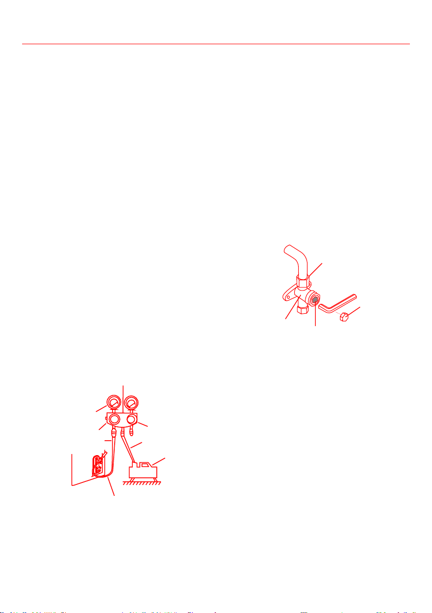
Evacuation Instructions
1. Connect the charge hose of the manifold
gauge to the service port on the outdoor unit’s
low pressure valve.
2. Connect another charge hose from the
manifold gauge to the vacuum pump.
3. Open the Low Pressure side of the manifold
gauge. Keep the High Pressure side closed.
4. Turn on the vacuum pump to evacuate the
system.
5. Run the vacuum for at least 15 minutes, or
(-10 5Pa).
Manifold Gauge
Compound gauge
-76cmHg
Low pressure valve
High pressure
valve
Pressure hose /
Charge hose
Charge hose
Vacuum
pump
Pressure gauge
Low pressure valve
6. Close the Low Pressure side of the manifold
gauge, and turn off the vacuum pump.
7. Wait for 5 minutes, then check that there has
been no change in system pressure.
8. If there is a change in system pressure, refer
to Gas Leak Check section for information on
how to check for leaks. If there is no change
in system pressure, unscrew the cap from the
packed valve (high pressure valve).
9. Insert hexagonal wrench into the packed valve
(high pressure valve) and open the valve by
turn. Listen for gas to exit the system, then
close the valve after 5 seconds.
10.
make sure that there is no change in pressure.
than atmospheric pressure.
11. Remove the charge hose from the service port.
Flare nut
Cap
valve body
valve stem
12. Using hexagonal wrench, fully open both the
high pressure and low pressure valves.
13. Tighten valve caps on all three valves (service
port, high pressure, low pressure) by hand. You
may tighten it further using a torque wrench if
needed.
OPEN VALVE STEMS GENTLY
When opening valve stems, turn the hexagonal
wrench until it hits against the stopper. Do not try
to force the valve to open further.
43
Air Evacuation
Note on Adding Refrigerant
Some systems require additional charging depending on pipe lengths. The standard pipe length varies
according to local regulations. For example, in North America, the standard pipe length is 25ft. In other
areas, the standard pipe length is 16ft. The refrigerant should be charged from the service port on the
outdoor unit’s low pressure valve. The additional refrigerant to be charged can be calculated using the
Connective Pipe
Length (m)
Air Purging
Method
Additional Refrigerant
length
Vacuum
Pump
length
Vacuum
Pump
R32:
R290:
R410A:
R22:
R32:
R290:
R410A:
R22:
CAUTION
DO NOT mix refrigerant types.
44
BEFORE TEST RUN
• Electrical Safety Checks
regulations, and according to the Installation Manual.
• Gas Leak Checks
•
• Check Grounding work - Measure grounding resistance by visual detection and with grounding
Note: This may not be required for some locations in the US.
DURING TEST RUN
1. Check for Electrical Leakage
During the Test Run, use an electro-probe and multimeter to perform a comprehensive electrical leakage
and resolve the cause of the leakage.
Note: This may not be required for some locations in the US.
A LICENSED ELECTRICIAN.
2. Gas Leak Checks
There are two different methods to check for gas leaks.
• Soap and Water Method
Using a soft brush, apply soapy water or liquid detergent to all pipe connection points on the indoor unit
and outdoor unit. The presence of bubbles indicates a leak.
• Leak Detector Method
If using leak detector, refer to the device’s operation manual for proper usage instructions.
• A
Check-point of indoor unit
Check-point of outdoor unit
A
B
C
D
A: Low pressure stop valve
45
Test Run
TEST RUN INSTRUCTIONS
You should perform the Test Run for at least 30
minutes.
1. Connect power to the unit.
2. Press the ON/OFF button on the remote
control to turn it on.
3. Press the MODE button to scroll through the
• COOL - Select lowest possible temperature
• HEAT - Select highest possible temperature
4. Let each function run for 5 minutes, and
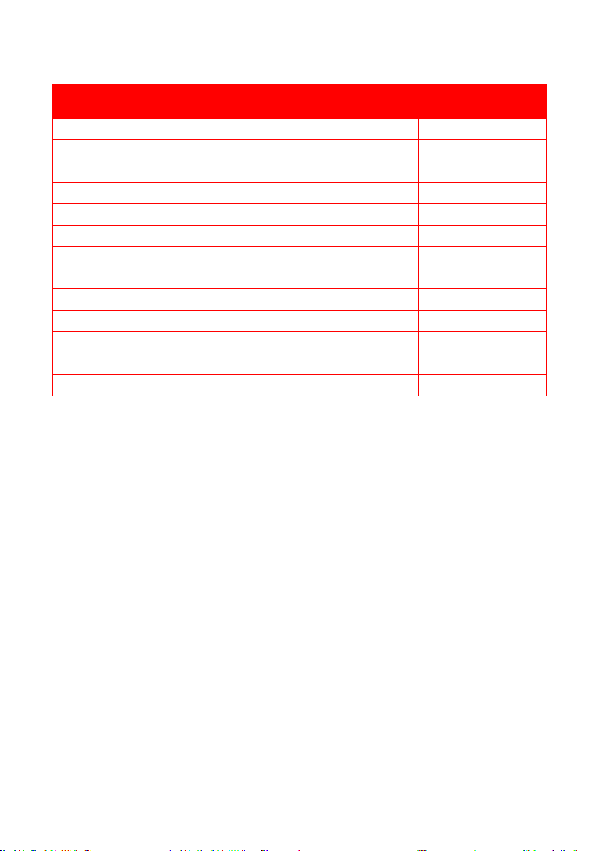
List of Checks to Perform PASS/FAIL
No electrical leakage
Unit is properly grounded
All electrical terminals
properly covered
Indoor and outdoor units
are solidly installed
All pipe connection points
do not leak
Outdoor
Indoor
Water drains properly
from drain hose
All piping is properly
insulated
Unit performs COOL
function properly
Unit performs HEAT
function properly
Indoor unit louvers rotate
properly
Indoor unit responds to
remote controller
Double-check Pipe Connections
During operation, the pressure of the refrigerant
circuit will increase. This may reveal leaks that
were not present during your initial leak check.
Take time during the Test Run to double-check
that all refrigerant pipe connection points do not
have leaks. Refer to Gas Leak Check section for
instructions.
5. After the Test Run is successfully completed,
of Checks to Perform have PASSED, take the
a. Using remote control, return unit to normal
operating temperature.
b. Using insulation tape, wrap the indoor
refrigerant pipe connections that you left
uncovered during the indoor unit installation
process.
IF AMBIENT TEMPERATURE IS BELOW 62°F
You can’t use the remote control to turn on the
COOL function when the ambient temperature
is below 62°F. In this instance, you can use the
MANUAL CONTROL button to test the COOL
function.
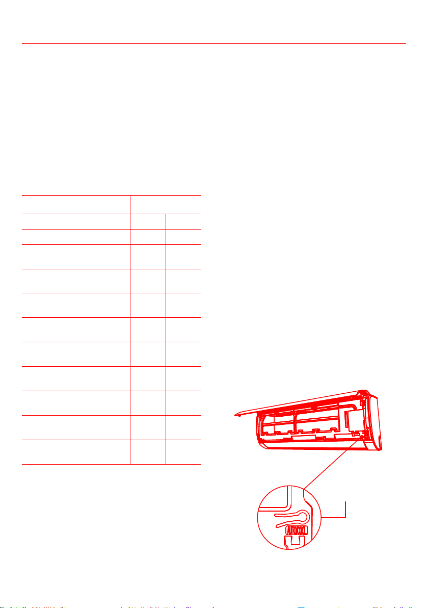
1. Lift the front panel of the indoor unit, and
raise it until it clicks in place.
2. The MANUAL CONTROL button is located on
the right-hand side of the unit. Press it twice
to select the COOL function.
3. Perform Test Run as normal.
Manual control button

46
Impedance Information
The impedance information is applicable to the following units only:
• This appliance MSAFB-12HRN1-QC6 can be connected only to a supply with system impedance no
more than 0.3730. In case necessary, please consult your supply authority for system impedance
information.
• This appliance MSAFD-17HRN1-QC5 can be connected only to a supply with system impedance no
more than 0.2100. In case necessary, please consult your supply authority for system impedance
information.
• This appliance MSAFD-22HRN1-QC6 can be connected only to a supply with system impedance no
more than 0.1290. In case necessary, please consult your supply authority for system impedance
information.
47
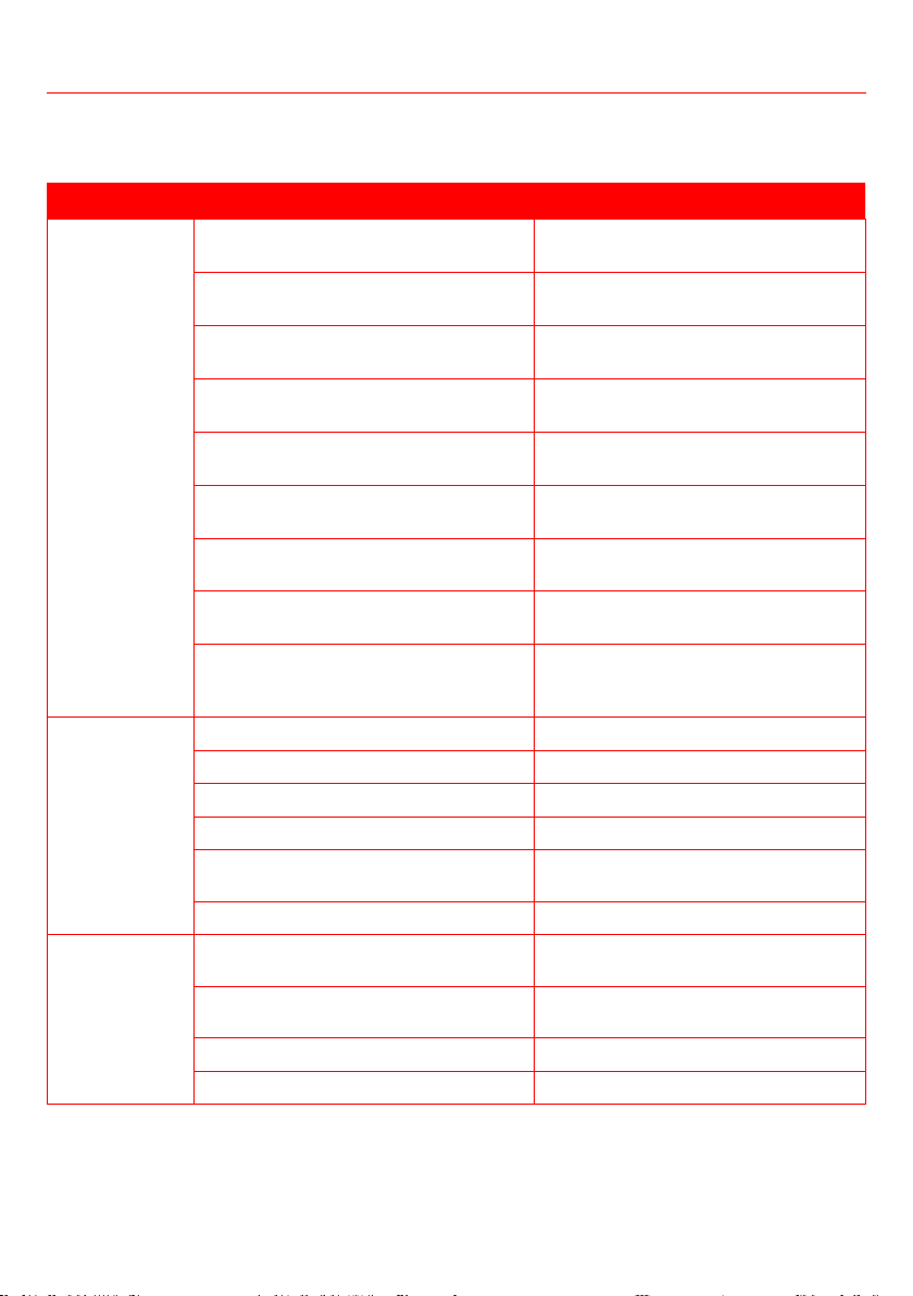
COMMON ISSUES
The following problems are not a malfunction and in most situations will not require repairs.
ISSUE POSSIBLE CAUSES
Unit does not turn on
when pressing ON/OFF
The Unit has a 3-minute protection feature that prevents the unit from
overloading. The unit cannot be restarted within three minutes of being turned
off.
The unit changes from
FAN mode
The unit may change its setting to prevent frost from forming on the unit.
Once the temperature increases, the unit will start operating in the previously
selected mode again.
The set temperature has been reached, at which point the unit turns off the
again.
The indoor unit emits
white mist
In humid regions, a large temperature difference between the room’s air and
the conditioned air can cause white mist.
Both the indoor and
outdoor units emit
white mist
When the unit restarts in HEAT mode after defrosting, white mist may be
emitted due to moisture generated from the defrosting process.
The indoor unit makes
noises
A rushing air sound may occur when the louver resets its position.
A squeaking sound may occur after running the unit in HEAT mode due to
expansion and contraction of the unit’s plastic parts.
Both the indoor unit
and outdoor unit make
noises
Low hissing sound when the system starts, has just stopped running, or is
or changing direction.
caused by temperature changes during operation can cause squeaking noises.
The outdoor unit
makes noises
The unit will make different sounds based on its current operating mode.
either the indoor or
outdoor unit
The unit may accumulate dust during extended periods of non-use, which will
be emitted when the unit is turned on. This can be mitigated by covering the
unit during long periods of inactivity.
The unit emits a bad
odor
The unit may absorb odors from the environment (such as furniture, cooking,
cigarettes, etc.) which will be emitted during operations.
The fan of the outdoor
unit does not operate
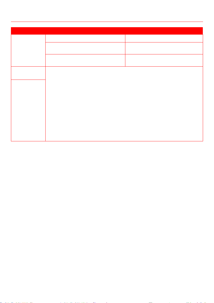
Operation is erratic,
unpredictable, or unit
is unresponsive
Interference from cell phone towers and remote boosters may cause the unit
to malfunction.
• Disconnect the power, then reconnect.
•
Note: If problem persists, contact a local dealer or your nearest customer service center. Provide them
with a detailed description of the unit malfunction as well as your model number.
Troubleshooting
48
When troubles occur, please check the following points before contacting a repair company.
PROBLEM POSSIBLE CAUSES SOLUTION
Poor Cooling
Performance
Temperature setting may be higher than
ambient room temperature
Lower the temperature setting
The heat exchanger on the indoor or
outdoor unit is dirty
Clean the affected heat exchanger
to instructions
The air inlet or outlet of either unit is
blocked
Turn the unit off, remove the obstruction
and turn it back on
Doors and windows are open Make sure that all doors and windows
are closed while operating the unit
Excessive heat is generated by sunlight Close windows and curtains during
periods of high heat or bright sunshine
Too many sources of heat in the room
(people, computers, electronics, etc.)
Reduce amount of heat sources
Low refrigerant due to leak or long-term
use
Check for leaks, re-seal if necessary and
top off refrigerant
SILENCE function is activated (optional
function)
SILENCE function can lower product
performance by reducing operating
frequency. Turn off SILENCE function.
The unit is not
working
Power failure Wait for the power to be restored
The power is turned off Turn on the power
The fuse is burned out Replace the fuse
Remote control batteries are out of power Replace batteries
The Unit’s 3-minute protection has been
activated
Wait three minutes after restarting the
unit
Timer is activated Turn timer off
The unit starts
and stops
frequently
There’s too much or too little refrigerant in
the system
Check for leaks and recharge the system
with refrigerant.
Incompressible gas or moisture has
entered the system.
Evacuate and recharge the system with
refrigerant
The compressor is broken Replace the compressor
The voltage is too high or too low Install a manostat to regulate the voltage
Troubleshooting
49
Troubleshooting
PROBLEM POSSIBLE CAUSES SOLUTION
Poor heating
performance
The outdoor temperature is extremely low Use auxiliary heating device
Cold air is entering through doors and
windows
Make sure that all doors and windows are
closed during use
Low refrigerant due to leak or long-term
use
Check for leaks, re-seal if necessary and
top off refrigerant
Indicator lamps
The unit may stop operation or continue to run safely. If the indicator lamps continue to
If not, disconnect the power, then connect it again. Turn the unit on. If the problem
persists, disconnect the power and contact your nearest customer service center.
Error code
appears and
begins with the
following in the
window display
of indoor unit:
• E(x), P(x), F(x)
•
EC(xx)
•
PC(xx)
Note: If your problem persists after performing the above checks and diagnostics, turn off your the unit
50
hOme
™
offers a limited two-year warranty (“warranty period”) on all of our products purchased new
and where a defect has arisen, wholly or substantially, as a result of faulty manufacture, parts or
workmanship during the warranty period. The warranty does not apply where damage is caused by
™
The hOme
™
warranty covers all costs related to restoring the proven defective product through repair or
A replacement product may be provided instead of repairing a defective product. hOme
™
’s exclusive
obligation under this warranty is limited to such repair or replacement.
A receipt indicating the purchase date is required for any claim, so please keep all receipts in a safe
greatly appreciated, the product registration is not required to activate any warranty and product
registration does not eliminate the need for the original proof of purchase.
The warranty becomes
those provided by hOme
™
, are used. You may also arrange for service after the warranty expires at an
additional cost.
These are our general terms for warranty service, but we always urge our customers to reach out to
us with any issue, regardless of warranty terms. If you have an issue with a hOme
™
product, please
contact us at 1-800-898-3002, and we will do our best to resolve it for you.
to state, country to country or province to province. The customer may assert any such rights at their
sole discretion.
Warranty
Manufacturing Info
This manual is to be used with all items with the model number
Keep all plastic bags away from children.
Warning
Contact Us
homelabs.com/chat
Mon–Fri 10AM–5PM EST
1-(800)-898-3002
Mon–Fri 10AM–5PM EST
Respond within twelve hours
CHAT W ITH US
CALL U S
EMAIL U S
HME030356N HME030357N HME030358N HME030359N HME030363N HME030364N
115V~60H, 1Ph (For


© 2016 hOme Technologies, LLC
37 East 18 Street, 7th Floor
New York, NY 10003
For household
Use Only
1-800-898-3002
All rights reserved, hOme
®
. Printed in China.