Owner 's Manual for Battery Charger
PREPARING TO CHARGE
- If necessary to remove battery from vehicle to charge, always remove grounded terminal from battery first. Make sure all accessories in the vehicle are off, so as not to cause an arc.
- Be sure area around battery is well ventilated while battery is being charged.
- Clean battery terminals. Be careful to keep corrosion from coming in contact with eyes.
- Add distilled water in each cell until battery acid reaches level specified by battery manufacturer. Do not overfill. For a battery without removable cell caps, such as valve regulated lead acid batteries, carefully follow manufacturer’s recharging instructions.
- Study all battery manufacturer’s specific precautions while charging and recommended rates of charge.
- Determine voltage of battery by referring to car owner’s manual and make sure that output voltage selector switch is set at correct voltage. If charger has adjustable charge rate, charge battery initially at lowest rate.
CHARGER LOCATION
- Locate charger as far away from battery as DC cables permit.
- Never place charger directly above battery being charged; gases from battery will corrode and damage charger.
- Never allow battery acid to drip on charger when reading electrolyte specific gravity or filling battery.
- Do not operate charger in a closed-in area or restrict ventilation in any way.
- Do not set a battery on top of charger.
DC CONNECTION PRECAUTIONS
- Connect and disconnect DC output clips only after setting any charger switches to “off” position and removing AC cord from electric outlet. Never allow clips to touch each other.
- Attach clips to battery and chassis, as indicated in sections 6 and 7.
FOLLOW THESE STEPS WHEN BATTERY IS INSTALLED IN VEHICLE
WARNING: A SPARK NEAR THE BATTERY MAY CAUSE A BATTERY EXPLOSION. TO REDUCE THE RISK OF A SPARK NEAR THE BATTERY:
- Position AC and DC cords to reduce risk of damage by hood, door, or moving engine part.
- Stay clear of fan blades, belts, pulleys, and other parts that can cause injury to persons.
- Check polarity of battery posts. POSITIVE (POS, P, +) battery post usually has larger diameter than NEGATIVE (NEG, N,–) post.
- Determine which post of battery is grounded (connected) to the chassis. If negative post is grounded to chassis (as in most vehicles), see (6.5). If positive post is grounded to the chassis, see (6.6).
- For negative-grounded vehicle, connect POSITIVE (RED) clip from battery charger to POSITIVE (POS, P, +) ungrounded post of battery. Connect NEGATIVE (BLACK) clip to vehicle chassis or engine block away from battery. Do not connect clip to carburetor, fuel lines, or sheet-metal body parts. Connect to a heavy gauge metal part of the frame or engine block.
- For positive-grounded vehicle, connect NEGATIVE (BLACK) clip from battery charger to NEGATIVE (NEG, N, –) ungrounded post of battery. Connect POSITIVE (RED) clip to vehicle chassis or engine block away from battery. Do not connect clip to carburetor, fuel lines, or sheet-metal body parts. Connect to a heavy gauge metal part of the frame or engine block.
- When disconnecting charger, turn switches to off, disconnect AC cord, remove clip from vehicle chassis, and then remove clip from battery terminal.
- See Operating Instructions for length of charge information.
FOLLOW THESE STEPS WHEN BATTERY IS OUTSIDE VEHICLE
WARNING: A SPARK NEAR THE BATTERY MAY CAUSE A BATTERY EXPLOSION. TO REDUCE THE RISK OF A SPARK NEAR THE BATTERY:
- Check polarity of battery posts. POSITIVE (POS, P, +) battery post usually has a larger diameter than NEGATIVE (NEG, N, –) post.
- Attach at least a 24-inch-long 6-gauge (AWG) insulated battery cable to NEGATIVE (NEG, N, –) battery post.
- Connect POSITIVE (RED) charger clip to POSITIVE (POS, P, +) post of battery.
- Position yourself and free end of cable as far away from battery as possible – then connect NEGATIVE (BLACK) charger clip to free end of cable.
- Do not face battery when making final connection.
- When disconnecting charger, always do so in reverse sequence of connecting procedure and break first connection while as far away from battery as practical.
- A marine (boat) battery must be removed and charged on shore. To charge it on board requires equipment specially designed for marine use.
GROUNDING AND AC POWER CORD CONNECTIONS
- This battery charger is for use on a nominal 120 volt circuit. The plug must be plugged into an outlet that is properly installed and grounded in accordance with all local codes and ordinances. The plug pins must fit the receptacle (outlet). Do not use with an ungrounded system.
- DANGER: Never alter the AC cord or plug provided – if it does not fit the outlet, have a proper grounded outlet installed by a qualified electrician. An improper connection can result in a risk of an electric shock or electrocution. NOTE: Pursuant to Canadian Regulations, use of an adapter plug is not allowed in Canada. Use of an adapter plug in the United States is not recommended and should not be used.
- USING AN EXTENSION CORD
The use of an extension cord is not recommended. If you must use an extension cord, follow these guidelines:
• Pins on plug of extension cord must be the same number, size, and shape as those of plug on charger.
• Ensure that the extension cord is properly wired and in good electrical condition.
• Wire size must be large enough for the AC ampere rating of charger, as specified:
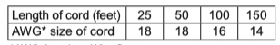
*AWG-American Wire Gauge
ASSEMBLY INSTRUCTIONS
- Remove all cord wraps and uncoil the cables prior to using the battery charger.
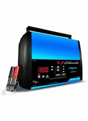
CONTROL PANEL
LED INDICATORS
 CLAMPS REVERSED (red) LED flashing: The connections are reversed.
 CHARGING (yellow/orange) LED lit: The charger is charging the battery.
 CHARGING (yellow/orange) LED flashing: The charger is in abort mode.
 CHARGED (green) LED pulsing: The battery is fully charged and the charger is in maintain mode.
NOTE: See Operating Instructions for a complete description of the charger modes.
DIGITAL DISPLAY
The display will show the battery VOLTAGE when the charger is not charging a battery. When it goes into charging mode, the display will automatically change to ON (to show charging has started) and then show the percent-of-charge of the battery being charged and either 6 or 12 (the voltage of the battery, determined by the charger). If you manually stop the charging process (by pressing the CHARGING RATE button) before the battery is fully charged, the display will show OFF.
NOTE: During charging, the display will go into sleep mode and will not show the percentage of charge or voltage of the battery. To turn the display back on, press any button.
• Battery % – The digital display shows an estimated charge percentage of the battery connected to the charger’s battery clamps.
• Voltage – The digital display shows the voltage at the charger battery clamps, in DC volts.
CHARGING RATE BUTTON
Use this button to select one of the following:
• 3A – For charging small batteries, such as those commonly used in garden tractors, snowmobiles and motorcycles. Also used to maintain fully charged large batteries.
• 15A – For charging automotive, marine and light truck batteries. Not intended for industrial applications.
BATTERY TYPE BUTTON
Use this button to select the battery type.
 – Used in cars, trucks and motorcycles, these batteries have vent caps and are often marked “low maintenance” or “maintenance-free”.
This type of battery is designed to deliver quick bursts of energy (such as starting engines) and has a greater plate count. The plates are thinner and have somewhat different material composition. Regular batteries should not be used for deep-cycle applications.
 – The Absorbed Glass Mat construction allows the electrolyte to be suspended in close proximity with the plate’s active material. In theory, this enhances both the discharge and recharge efficiency. The AGM batteries are a variant of Sealed VRLA (valve regulated lead-acid) batteries. Popular uses include highperformance engine starting, power sports, deep-cycle, solar and storage batteries.
 – The electrolyte in a GEL cell has a silica additive that causes it to set up or stiffen. The recharge voltages on this type of cell are lower than those for other styles of lead-acid battery. This is probably the most sensitive cell in terms of adverse reactions to overvoltage charging. Gel batteries are best used in VERY DEEP cycle application and may last a bit longer in hot weather applications. If the wrong battery charger is used on a gel cell battery, poor performance and premature failure will result.
OPERATING INSTRUCTIONS
WARNING: A spark near the battery may cause an explosion.
IMPORTANT: Do not start the vehicle with the charger connected to the AC outlet, or it could result in damage to the charger.
NOTE: This charger is equipped with an auto-start feature. Current will not be supplied to the battery clamps until a battery is properly connected. The clamps will not spark if touched together.
CHARGING A BATTERY IN THE VEHICLE
1. Turn off all the vehicle’s accessories.
2. Keep the hood open.
3. Clean the battery terminals.
4. Place the charger on a dry, nonflammable surface.
5. Lay the AC/DC cables away from any fan blades, belts, pulleys and other moving parts.
6. Connect the battery, following the precautions listed in sections 6 and 7.
7. Connect the charger to an electrical outlet.
8. Select the battery type and charging rate.
9. When charging is complete, disconnect the charger from the AC power, remove the clamps from the vehicle’s chassis, and then remove the clamp from the battery terminal.
CHARGING A BATTERY OUTSIDE OF THE VEHICLE
1. Place battery in a well-ventilated area.
2. Clean the battery terminals.
3. Connect the battery, following the precautions listed in sections 6 and 7.
4. Connect the charger to the electrical outlet.
5. Select the battery type and charging rate.
6. When charging is complete, disconnect the charger from the AC power, disconnect the negative clamp, and finally the positive clamp.
7. A marine (boat) battery must be removed and charged on shore.
CHARGE RATE
The charger will automatically adjust the charging current, based on battery size, in order to charge the battery completely, efficiently and safely.
BATTERY CHARGING TIMES
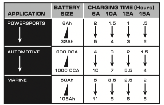
Times are based on a 50% discharged battery and may change, depending on age and condition of battery.
AUTOMATIC CHARGING MODE
When the Automatic Charge is performed, the charger switches to the maintain mode automatically after the battery is charged.
ABORTED CHARGE
If charging cannot be completed normally, charging will abort. When charging aborts, the charger’s output is shut off and the CHARGING (yellow/orange) LED will flash. To reset after an aborted charge, unplug the charger from the AC outlet, wait a few moments and plug it back in. DESULFATION MODE Desulfation could take 8 to 10 hours.
If desulfation fails, charging will abort and the CHARGING (yellow/orange) LED will flash.
COMPLETION OF CHARGE
Charge completion is indicated by the CHARGED (green) LED. When pulsing, the charger has switched to the maintain mode of operation.
MAINTAIN MODE (FLOAT-MODE MONITORING)
When the CHARGED (green) LED is pulsing, the charger has started maintain mode. In this mode, the charger keeps the battery fully charged by delivering a small current when necessary. If the charger has to provide its maximum maintain current for a continuous 12 hour period, it will go into abort mode (see Aborted Charge section). This is usually caused by a drain on the battery or the battery could be bad. Make sure there are no loads on the battery. If there are, remove them. If there are none, have the battery checked or replaced.
MAINTAINING A BATTERY
The SC1304 maintains both 6 and 12 volt batteries, keeping them at full charge. NOTE: The maintain mode technology allows you to safely charge and maintain a healthy battery for extended periods of time. However, problems with the battery, electrical problems in the vehicle, improper connections or other unanticipated conditions could cause excessive current draws. As such, occasionally monitoring your battery and the charging process is required.
USING THE BATTERY VOLTAGE TESTER
1. With the charger unplugged from the AC outlet, connect the charger to the battery following the instructions given in previous sections.
2. Plug the charger AC power cord into the AC outlet.
3. If necessary, press the BATTERY TYPE button until the correct type is indicated.
4. Read the voltage on the digital display. Keep in mind that this reading is only a battery voltage reading; a false surface charge may mislead you. Compare the reading to the chart below.
|
6 V Battery Voltage Reading
|
12 V Battery Voltage Reading
|
Battery Condition
|
|
6.4 or more
|
12.8 or more
|
Charged
|
|
6.1 to 6.3
|
12.2 to 12.7
|
Needs charging
|
|
Less than 6.1
|
Less than 12.2
|
Discharged
|
POWER-UP IDLE TIME LIMIT
If no button is pressed within 10 minutes after the battery charger is first powered up, the charger will automatically switch from tester to charger if a battery is connected. In that case, the charger will be set to charge at the 3A rate and gel cell battery type.
TESTING AFTER CHARGING
After the unit has been changed from tester to charger (by selecting a charge rate), it remains a charger. To change the battery charger back to a tester, press the CHARGING RATE button until all charge rate LEDs are off.
MAINTENANCE AND CARE
A minimal amount of care can keep your battery charger working properly for years.
• Clean the clamps each time you are finished charging. Wipe off any battery fluid that may have come in contact with the clamps to prevent corrosion.
• Occasionally cleaning the case of the charger with a soft cloth will keep the finish shiny and help prevent corrosion.
• Coil the input and output cords neatly when storing the charger. This will help prevent accidental damage to the cords and charger.
• Store the charger unplugged from the AC power outlet, in an upright position.
• Store inside, in a cool, dry place. Do not store the clamps clipped together, clipped to the handle, on or around metal, or clipped to the cables.
TROUBLESHOOTING/ERROR CODES
Error Codes
|
ERROR CODE
|
DESCRIPTION
|
REASON/SOLUTION
|
|
F01
|
The battery voltage is still under 10V (for a 12V battery) or 5V (for a 6V battery) after 2 hours of charging.
|
The battery could be bad. Have it checked or replaced.
|
|
F02
|
The charger cannot desulfate the battery.
|
The battery could not be desulfated; have it checked or replaced.
|
|
F03
|
The battery was unable to reach the “full charge” voltage.
|
May be caused by trying to charge a large battery or bank of batteries on too low of a current setting. Try again with a higher current setting or have the battery checked or replaced.
|
|
F04
|
The connections to the battery are reversed.
|
The battery is connected backwards. Unplug the charger and reverse the connections to the battery.
|
|
F05
|
The charger was unable to keep the battery fully charged in maintain mode.
|
The battery won’t hold a charge. May be caused by a drain on the battery or the battery could be bad. Make sure there are no loads on the battery. If there are remove them. If there are none, have the battery checked or replaced.
|
|
F06
|
The charger detected that the battery may be getting too hot (thermal runaway).
|
The charger automatically shuts the current off if it detects the battery may be getting too hot. Have the battery checked or replaced.
|
If you get an error code, check the connections and settings and/or replace the battery.
Troubleshooting
|
PROBLEM
|
POSSIBLE CAUSE
|
SOLUTION
|
|
Battery clamps do not spark when touched together.
|
The charger is equipped with an auto-start feature.
It will not supply current to the battery clamps until a battery is properly connected. The clamps will not spark if touched together.
|
No problem; this is a normal condition.
|
|
Three LEDs come on for 2 seconds, then turn off.
|
The charger is plugged into an AC outlet.
|
No problem; this is normal.
|
|
The charger will not turn on when properly connected.
|
AC outlet is dead.
Poor electrical connection.
Battery is defective.
|
Check for open fuse or circuit breaker supplying AC outlet.
Check power cord and extension cord for loose fitting plug.
Have the battery checked.
|
|
I cannot select a 6V or 12V setting.
|
The charger is equipped with Auto Voltage Detection, which automatically detects the voltage and charges the battery.
|
No problem; this is normal.
|