Loading ...
Loading ...
Loading ...
Adjustments
AUGER DRIVE ADJUSTMENT
WARNING
Do not over=tighten, as this may lift the lever and
cause auger drive to be engaged without depress=
ing the Auger Control.
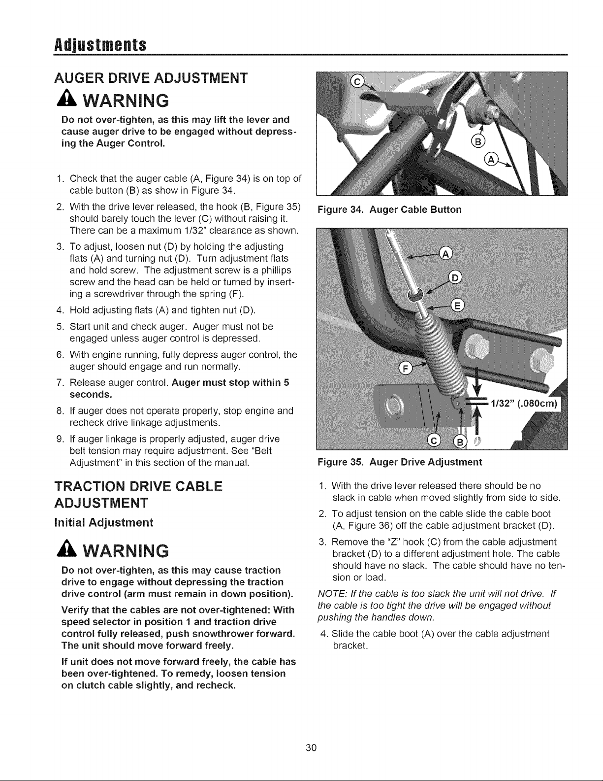
1. Check that the auger cable (A, Figure 34) is on top of
cable button (B) as show in Figure 34.
2. With the drive lever released, the hook (B, Figure 35)
should barely touch the lever (C) without raising it.
There can be a maximum 1/32" clearance as shown.
3. To adjust, loosen nut (D) by holding the adjusting
flats (A) and turning nut (D). Turn adjustment flats
and hold screw. The adjustment screw is a phillips
screw and the head can be held or turned by insert-
ing a screwdriver through the spring (F).
,
5.
Hold adjusting flats (A) and tighten nut (D).
Start unit and check auger. Auger must not be
engaged unless auger control is depressed.
6. With engine running, fully depress auger control, the
auger should engage and run normally.
7. Release auger control. Auger must stop within 5
seconds.
,
,
If auger does not operate properly, stop engine and
recheck drive linkage adjustments.
If auger linkage is properly adjusted, auger drive
belt tension may require adjustment. See "Belt
Adjustment" in this section of the manual.
TRACTION DRIVE CABLE
ADJUSTMENT
initial Adjustment
WARNING
Do not over=tighten, as this may cause traction
drive to engage without depressing the traction
drive control (arm must remain in down position).
Verify that the cables are not over=tightened: With
speed selector in position 1 and traction drive
control fully released, push snowthrower forward.
The unit should move forward freely.
If unit does not move forward freely, the cable has
been over=tightened. To remedy, loosen tension
on clutch cable slightly, and recheck.
Figure 34. Auger Cable Button
Figure 35. Auger Drive Adjustment
1. With the drive lever released there should be no
slack in cable when moved slightly from side to side.
2. To adjust tension on the cable slide the cable boot
(A, Figure 36) off the cable adjustment bracket (D).
3. Remove the "Z" hook (C) from the cable adjustment
bracket (D) to a different adjustment hole. The cable
should have no slack. The cable should have no ten-
sion or load.
NOTE: If the cable is too slack the unit will not drive. If
the cable is too tight the drive will be engaged without
pushing the handles down.
4. Slide the cable boot (A) over the cable adjustment
bracket.
30
Loading ...
Loading ...
Loading ...