
Loading ...
Loading ...
Loading ...
ENGLISH
8
INTENDED USE
This reciprocating saw is designed for professional
sawingapplications.
DO NOT use under wet conditions or in presence of
flammable liquids orgases.
This reciprocating saw is a professional power tool. DO NOT
let children come into contact with the tool. Supervision is
required when inexperienced operators use thistool.
Variable Speed Trigger Switch (Fig. A, D)
Lock-Off Button and Trigger Switch
Your saw is equipped with a lock-off button
2
.
To lock the trigger switch, press the lock-off button as
shown in FigureD. Always lock the trigger switch
1
when
carrying or storing the tool to eliminate unintentional
starting. The lock-off button is colored red to indicate when
the switch is in its unlocked position.
To unlock the trigger switch, press the lock-off button as
shown in FigureD. Pull the trigger switch to turn the motor
ON. Releasing the trigger switch turns the motor OFF.
UNLOCKED
LOCKED
2
Fig. D
1
WARNING: This tool has no provision to lock the
switch in the ON position, and should never be locked
ON by any other means.
The variable speed trigger switch will give you added
versatility. The further the trigger is depressed the higher
the speed of the saw.
CAUTION: Use of very slow speed is recommended
only for beginning a cut. Prolonged use at very slow
speed may damage your saw.
Worklight
CAUTION: Do not stare into worklight. Serious eye
injury could result.
There is a worklight located on the end of the tool near the
shoe. The worklight is activated when the trigger switch
is depressed, and will remain on for a short time after the
trigger switch is released. If the trigger switch remains
depressed, the worklight will remain on.
NOTE: The worklight is for lighting the immediate work
surface and is not intended to be used as a flashlight.
OPERATION
WARNING: To reduce the risk of serious personal
injury, turn unit off and remove the battery pack
before making any adjustments or removing/
installing attachments or accessories. An
accidental start-up can causeinjury.
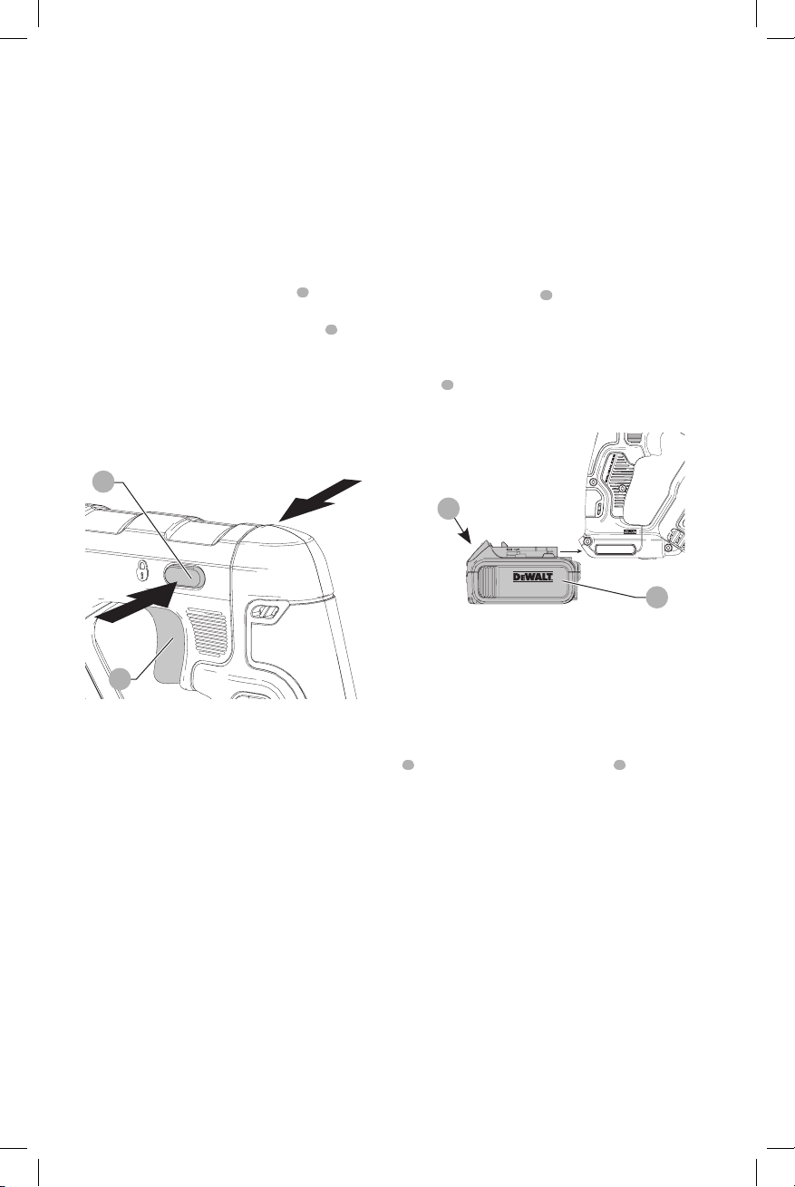
Installing and Removing the Battery Pack
(Fig. E)
NOTE: For best results, make sure your battery pack is
fullycharged.
To install the battery pack
6
into the tool handle, align the
battery pack with the rails inside the tool’s handle and slide
it into the handle until the battery pack is firmly seated in
the tool and ensure that it does notdisengage.
To remove the battery pack from the tool, press the release
button
7
and firmly pull the battery pack out of the tool
handle. Insert it into the charger as described in the charger
section of thismanual.
Fig. E
6
7
Proper Hand Position (Fig. K)
WARNING: To reduce the risk of serious personal injury,
ALWAYS use proper hand position as shown.
WARNING: To reduce the risk of serious personal injury,
ALWAYS hold securely in anticipation of a sudden
reaction.
Proper hand position requires one hand on the main handle
8
and the other hand on the hand grip
5
.
Blade Installation and Removal
(Fig. F–H)
WARNING: To reduce the risk of serious personal
injury, turn unit off and remove the battery pack
before making any adjustments or removing/
installing attachments or accessories. An
accidental start-up can causeinjury.
Different blade lengths are available. Use the appropriate
blade for the application. The blade should be longer than
3–1/2" (89 mm) and should extend past the shoe and the
thickness of the workpiece during the cut. Do not use jigsaw
blades with this tool.
WARNING: Cut hazard. Blade breakage may occur
if the blade does not extend past the shoe and the
workpiece during the cut (Fig.F). Increased risk of
personal injury, as well as damage to the shoe and
workpiece may result.
Loading ...
Loading ...
Loading ...