Loading ...
Loading ...
Loading ...
MAINTENANCE
27
F–000700L
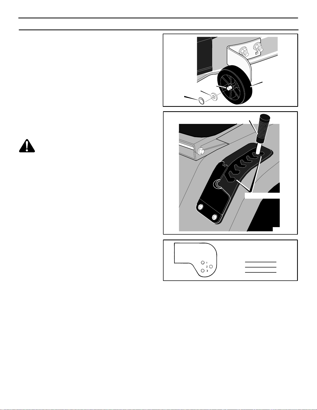
HOW TO ADJUST THE GAUGE WHEELS
The axle bolts for the gauge wheels were mounted in the LOW cut
position. To change the position of the gauge wheels, move the axle
bolts as follows.
IMPORTANT: Before you adjust the gauge wheels, you must do
the following. Make sure the mower housing is level. Make sure
the height of cut is set at the height you want for your lawn.
Mow a short distance on a flat level area and look at the area
that was cut. If the mower housing does not cut level, see the
instructions “How To Level The Mower Housing.”
WARNING: Before you make an inspection, adjust-
ment, or repair to the unit, disconnect the wire to the
spark plug. Remove the spark plug wire to prevent
the engine from starting by accident.
1. Remove the gauge wheels (Figure 23).
2. Mow a short distance on a flat level area to check the level of
cut and the height of cut. Look at the height of cut position
number on the lift lever (Figure 24).
3. Look at each gauge wheel bracket. There are 3 holes in each
bracket and a number next to each hole. The number for the
height of cut position on the lift lever indicates the correct hole
to use on each gauge wheel bracket (Figure 25).
4. Assemble the axle bolts to the gauge wheel brackets using
the correct hole in the bracket as indicated (Figure 25).
NOTE: If the height of cut position is changed by the lift lever,
you must move the gauge wheels to the correct hole
(Figure 25) to keep a level height of cut.
Gauge Wheel
Figure 23
Locking
Ring
Washer
Axle Bolt
Figure 24
Cutting Height Positions
Lift Lever
Wheel Bracket
Hole No.
Lift Lever
Position No.
1 1
2 2
3 3,4,5,6
Gauge
Wheel Bracket
Figure 25
Loading ...
Loading ...
Loading ...