Loading ...
Loading ...
Loading ...
©2016 Hestan Commercial Corporation
21
EN
BURNER ADJUSTMENTS
Hestan grills feature the unique Trellis Burner
™
, and infrared Rotisserie and Sear Burners. The
following instructions apply only to the Trellis Burner.
TRELLIS BURNER
™
FLAME ADJUSTMENT
Each grill burner is tested and adjusted at the factory prior to shipment. The proper orifice for
the gas type, and the air-fuel (air shutter) adjustment was made at this time. However, variations
in the local gas supply, the elevation where you live, converting from one gas type to another, and
other factors might make it necessary to adjust the burner flames.
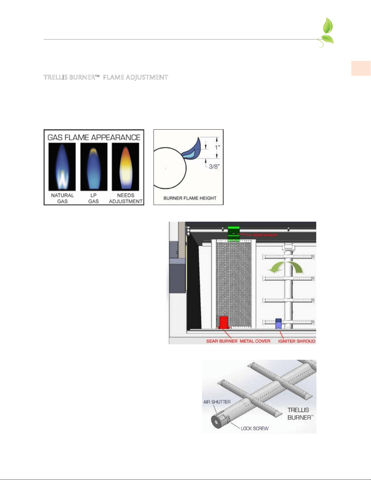
The flames of the burners should be visually checked and compared with the figures below.
Flames should be blue and stable
with no yellow tips (LP units
will have some yellow tipping).
There should be no excessive
noise or flame lifting. If any of
these conditions exist, remove
the burners and check if dirt,
debris, spider webs, etc., are
blocking the air shutter or burner
ports. Proceed with air shutter
adjustment if necessary.
AIR SHUTTER ADJUSTMENT
Remove the control panel to gain access to the orifice
area and air shutters on the burners. A metal cap at
the inlet of the burner called the “AIR SHUTTER”
regulates the amount of air that enters into the
burner for combustion (see Fig. 4). The air shutter
has a lock screw which must be loosened prior to
adjustment. Remove the burner carefully from the
grill. With a marker pen, mark the current location
of the shutter opening, then loosen the screw of the
air shutter. Reinstall the burner. Make certain that
the burners are sitting properly on the orifices taking
care not to move or damage the igniter electrodes.
Reinstall the radiant trays.
BURNER REMOVAL BEFORE
AIR SHUTTER ADJUSTMENT
Open your grill and remove the grates,
radiant trays, and burners from the
firebox area. Trellis burners are removed
by lifting up the rear of the burner, and
carefully twisting to clear the igniter
shroud. Sear burners have a small metal
cover over the igniter which must be
removed first. There is also a screw at
the rear firebox wall which must be
removed. The sear burner can then
be carefully removed using the same
twisting action to avoid breaking the
ceramic igniter.
Figure 4
GAS CONNECTIONS
(continued)
Loading ...
Loading ...
Loading ...