Loading ...
Loading ...
Loading ...
MAJOR COMPONENTS / PIPING
Pressure Switch
The pressure switch provides automatic control.
MODEL NO. PUMP STARTS AT PUMP STOPS AT
390.251483 40 PSI 60 PSI
390.251883 40 PSI 60 PSI
Tank
The tank serves two functions. It provides a reservoir of water,
some of which can be drawn through the house fixture before the
pump must start. It maintains a cushion of air under pressure.
Two types of tanks are available. Captive Air _ and Standard. No air
volume control is needed with Captive Air* Tanks.
PIPING IN THE WELL
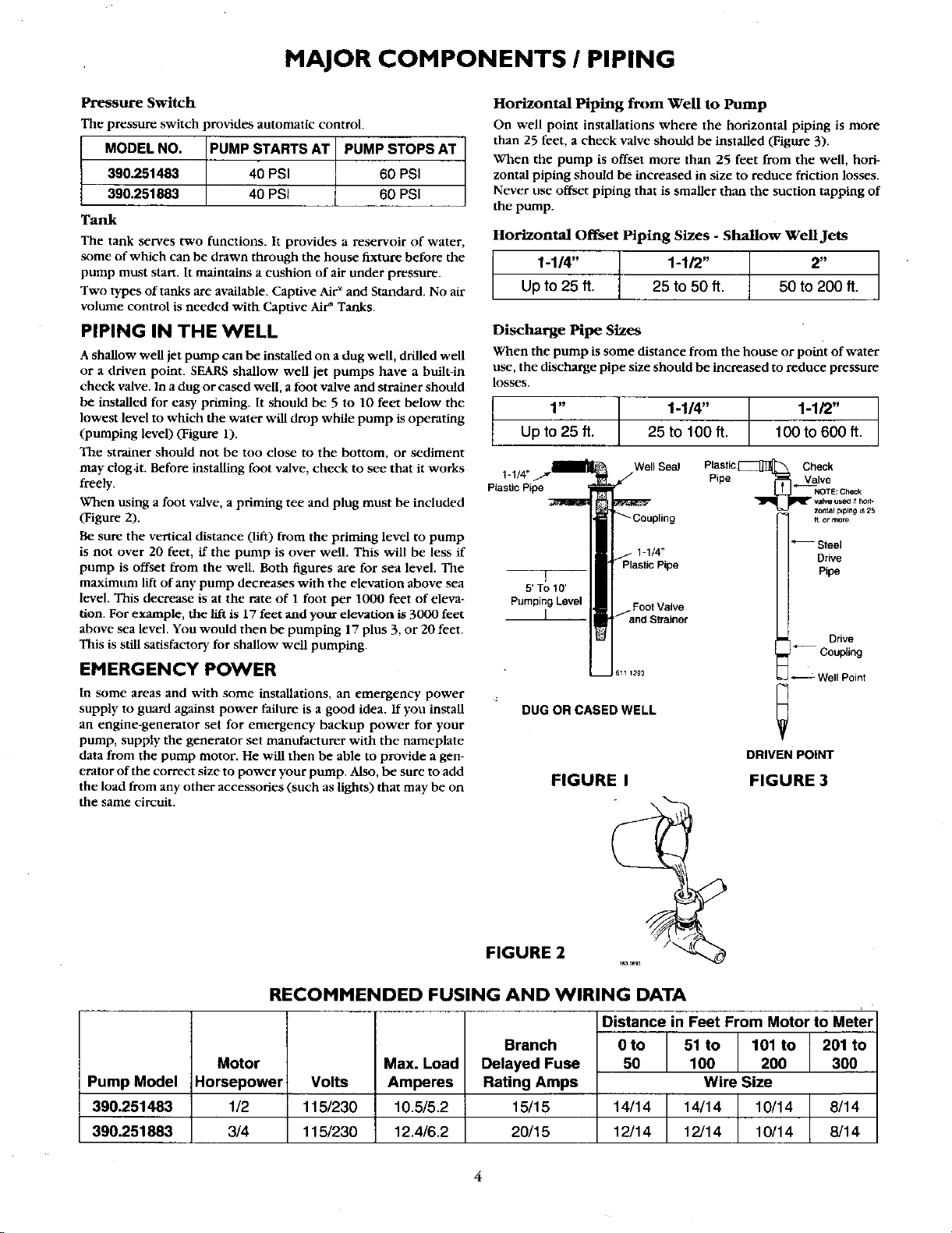
A shallow well jet pump can be installed on a dug well, drilled well
or a driven point. SEARS shallow well jet pumps have a built-in
check valve. In a dug or cased well, a foot valve and strainer should
be installed for easy priming. It should be 5 to 10 feet below the
lowest level to which the water will drop while pump is operating
(pumping level) (Figure 1).
The strainer should not be too close to the bottom, or sediment
may clog.it. Before installing foot valve, check to see that it works
freely.
When using a foot valve, a priming tee and plug must be included
(Figure 2).
Be sure the vertical distance (lift) from the priming level to pump
is not over 20 feet, if the pump is over well. This will be less if
pump is offset from the well. Both figures are for sea level. The
maximum lift of any pump decreases with the elevation above sea
level. This decrease is at the rate of 1 foot per 1000 feet of eleva-
tion. For example, the lift is 17 feet and your elevation is 3000 feet
above sea level. You would then be pumping 17 plus 3, or 20 feet.
This is still satisfactory for shallow well pumping.
EMERGENCY POWER
In some areas and with some installations, an emergency power
supply to guard against power failure is a good idea. If you install
an engine-generator set for emergency backup power for your
pump, supply the generator set manufacturer with the nameplate
data from the pump motor. He will then be able to provide a gen-
erator of the correct size to power your pump. Also, be sure to add
the load from any other accessories (such as lights) that may be on
the same circuit.
Horizontal Piping from Well to Pump
On well point installations where the horizontal piping is more
than 25 feet, a check valve should be installed (Figure 3).
When the pump is offset more than 25 feet from the well, hori-
zontal piping should be increased in size to reduce friction losses.
Never use offset piping that is smaller than the suction tapping of
the pump.
Horizontal Offset Piping Sizes - Shallow Well Jets
1-1/4" t 1-1/2" t 2"
Up to 25 ft. 25 to 50 ft. 50 to 200 ft.
Discharge Pipe Sizes
When the pump is some distance from the house or point of water
use, the discharge pipe size should be increased to reduce pressure
losses.
1" 1-1/4" | 1-1/2"
Up to 25 ft. 25 tolOOft. T 100 to 600 ft.
Plastic C_leck
1-1/4" WellSeal
Pipe ._aValve
NOTE: Check
valve useO _fhow
zontal p_ping _s25
or more
Plastic Pipe
1-1/4"
T
5' TOtO'
Pumping Lovel FootValve
1
DUG OR CASED WELL
Steel
Drive
Pipe
Drive
Coupling
Well Point
DRIVEN POINT
FIGURE I FIGURE 3
\
FIGURE 2
Pump Model
390.251483
390.251883
Motor
Horsepower
1/2
RECOMMENDED FUSING AND WIRING DATA
Distance in Feet From Motor to Meter
Volts
115/230
115/230
Max. Load
Amperes
10.5/5.2
Branch
Delayed Fuse
Rating Amps
1_15
Oto 51 to 101 to 201 to
50 100 200 300
Wire Size
14/14 14/14 10/14 8/14
3/4 12.4/6.2 20/15 12/14 12/14 10/14 8/14
4
Loading ...
Loading ...
Loading ...