Loading ...
Loading ...
Loading ...
11
Attaching the Wood Frame to the Door
((DDFFUURR MMOODDEELL))
1. If the door is attached to the unit, remove by unscrewing the top allen head set screw at the top hinge. Remove
the door by angling the door off of the bottom hinge pin.
2. Peel back the door gasket to expose the screw holes.
3. Set the wood frame flush to the front of the door in the desired location. Clamp the wood frame to the door if
necessary.
4. Insert the wood screws through the back of the door into the pilot holes in the wood frame and tighten.
5. Reinstall the door gasket by pressing into the door channel. Make certain the corners are inserted fully.
6. Install the door to the unit. Use the supplied plastic washer as shown in the figure below.
7. Realigning the door may be necessary. Any final door adjustments can be made using a 1/8” allen head driver to
adjust the door’s hinges. (See figure below)
8. Attach the door to the unit by reversing step number 1 above.
Magnetic door
gasket
Rear of Door
Bottom of door
Attached wood frame
3/8” clearance
holes for
frame wood
screws -
10 holes
Door hinge
adjustment screws
Attaching the Handle
Attach the handle of your choice by drilling mounting holes through panel. Countersink or counterbore holes from back
side of panel for handle screw heads to be flush.
CAUTION
Door can become
disengaged if washers
are not installed.
C
AUTION
D
oor can become
d
isengaged if
washers are not
i
nstalled.
Cabinet
Hinge
Wood
Frame
Door Hinge
Door Hinge
Shoulder bushing
3/4” OD x 7/16”
ID Washer
3/4” OD x 1/4” ID
Washer
(3) Nylon hardware
components at
bottom hinge
CAUTION
Door may not swing properly
if all nylon components are
not installed as shown
Bottom Hinge Cover
Wood Frame
HHiinnggee HHaarrddwwaarree IInnssttaallllaattiioonn
DDeettaaiillss
5/8”x 7/32” ID washer
Shoulder
bushing
(2) Nylon
hardware
c
omponents at
top hinge
Top Hinge Cover
10
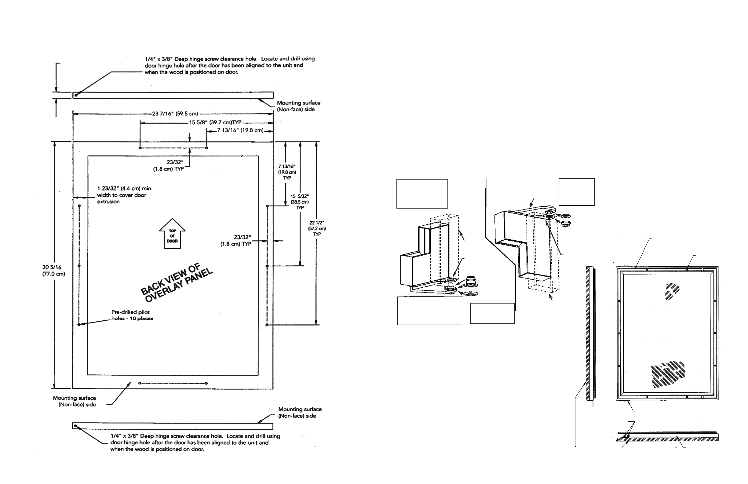
Selecting and Preparing the Wood Frame - 24” W. DFUR Model
FFOORR AA 33--11//22”” TTOOEE KKIICCKK
((CCOOVVEERRSS TTHHEE EENNTTIIRREE DDOOOORR EEXXTTRRUUSSIIOONN))
-
-
-
-
-
-
-
-
MMiinn.. 55//88”” ((11..77 ccmm))
MMaaxx.. 33//44”” ((11..99 ccmm))
1/8” allen head screws for hinge
adjustment
Loading ...
Loading ...
Loading ...