Owner’s Manual
ENGLISH
Hybrid Digital DAC Amplier
© NAD C 399
®
C 399
ENGLISH
2
• Read instructions - All the safety and operating instructions should be read
before the product is operated.
• Retain instructions - The safety and operating instructions should be retained
for future reference.
• Heed Warnings - All warnings on the product and in the operating instructions
should be adhered to.
• Follow Instructions - All operating and use instructions should be followed.
• Cleaning - Unplug this product from the wall outlet before cleaning. Do not use
liquid cleaners or aerosol cleaners. Use a damp cloth for cleaning.
• Attachments - Do not use attachments not recommended by the product
manufacturer as they may cause hazards.
• Water and Moisture - Do not use this product near water-for example, near a
bath tub, wash bowl, kitchen sink, or laundry tub; in a wet basement; or near a
swimming pool; and the like.
• Accessories - Do not place this product on an unstable cart, stand, tripod,
bracket, or table. The product may fall, causing serious injury to a child or adult
and serious damage to the product. Use only with a cart, stand, tripod, bracket,
or table recommended by the manufacturer, or sold with the product. Any
mounting of the product should follow the manufacturer’s instructions, and
should use a mounting accessory recommended by the manufacturer.
• Cart - A product and cart combination should be moved with care.
Quick stops, excessive force, and uneven surfaces may cause the
product and cart combination to overturn.
• Ventilation - Slots and openings in the cabinet are provided for ventilation
to ensure reliable operation of the product and to protect it from overheating.
These openings must not be blocked or covered. The openings should never be
blocked by placing the product on a bed, sofa, rug, or other similar surface. This
product should not be placed in a built-in installation such as a bookcase or rack
unless proper ventilation is provided or the manufacturer’s instructions have been
adhered to.
• Power Sources - This product should be operated only from the type of power
source indicated on the marking label and connected to a MAINS socket outlet
with a protective earthing connection. If you are not sure of the type of power
supply to your home, consult your product dealer or local power company.
• Power–Cord Protection - Power-supply cords should be routed so that they
are not likely to be walked on or pinched by items placed upon or against them,
paying particular attention to cords at plugs, convenience receptacles, and the
point where they exit from the product.
• Mains Plug - Where the mains plug or an appliance coupler is used as the
disconnect device, the disconnect device shall remain readily operable.
• Outdoor Antenna Grounding - If an outside antenna or cable system is
connected to the product, be sure the antenna or cable system is grounded so
as to provide some protection against voltage surges and built-up static charges.
Article 810 of the National Electrical Code, ANSI/NFPA 70, provides information
with regard to proper grounding of the mast and supporting structure, grounding
of the lead-in wire to an antenna discharge unit, size of grounding conductors,
location of antenna discharge unit, connection to grounding electrodes, and
requirements for the grounding electrode.
• Lightning - For added protection for this product during a lightning storm, or
when it is left unattended and unused for long periods of time, unplug it from the
wall outlet and disconnect the antenna or cable system. This will prevent damage
to the product due to lightning and power-line surges.
• Power Lines - An outside antenna system should not be located in the vicinity
of overhead power lines or other electric light or power circuits, or where it can
fall into such power lines or circuits. When installing an outside antenna system,
extreme care should be taken to keep from touching such power lines or circuits
as contact with them might be fatal.
• Overloading - Do not overload wall outlets, extension cords, or integral
convenience receptacles as this can result in a risk of re or electric shock.
• Flame Sources - No naked ame sources, such as lighted candles, should be
placed on the product.
• Object and Liquid Entry - Never push objects of any kind into this product
through openings as they may touch dangerous voltage points or short-out parts
that could result in a re or electric shock. Never spill liquid of any kind on the
product.
• Headphones - Excessive sound pressure form earphones and headphones can
cause hearing loss.
• Damage Requiring Service - Unplug this product from the wall outlet and refer
servicing to qualied service personnel under the following conditions:
– When the power-supply cord or plug is damaged.
– If liquid has been spilled, or objects have fallen into the product.
– If the product has been exposed to rain or water.
– If the product does not operate normally by following the operating
instructions. Adjust only those controls that are covered by the operating
instructions as an improper adjustment of other controls may result in
damage and will often require extensive work by a qualied technician to
restore the product to its normal operation.
– If the product has been dropped or damaged in any way.
– When the product exhibits a distinct change in performance-this indicates a
need for service.
• Replacement Parts - When replacement parts are required, be sure the service
technician has used replacement parts specied by the manufacturer or have the
same characteristics as the original part. Unauthorized substitutions may result in
re, electric shock, or other hazards.
• Battery Disposal - When disposing of used batteries, please comply with
governmental regulations or environmental public instruction’s rules that apply in
your country or area.
• Safety Check - Upon completion of any service or repairs to this product, ask the
service technician to perform safety checks to determine that the product is in
proper operating condition.
• Wall or Ceiling Mounting - The product should be mounted to a wall or ceiling
only as recommended by the manufacturer.
WARNING
THE LIGHTNING FLASH WITH ARROWHEAD SYMBOL, WITHIN AN
EQUILATERAL TRIANGLE, IS INTENDED TO ALERT THE USER TO THE
PRESENCE OF UNINSULATED “DANGEROUS VOLTAGE” WITHIN THE
PRODUCT’S ENCLOSURE THAT MAY BE OF SUFFICIENT MAGNITUDE
TO CONSTITUTE A RISK OF ELECTRIC SHOCK TO PERSONS
THE EXCLAMATION POINT WITHIN AN EQUILATERAL TRIANGLE IS
INTENDED TO ALERT THE USER TO THE PRESENCE OF IMPORTANT
OPERATING AND MAINTENANCE SERVICING INSTRUCTIONS IN THE
LITERATURE ACCOMPANYING THE APPLIANCE.
CAUTION REGARDING PLACEMENT
To maintain proper ventilation, be sure to leave a space around the unit (from the
largest outer dimensions including projections) than is equal to, or greater than
shown below.
Left and Right Panels: 10 cm
Rear Panel: 10 cm
Top Panel: 10 cm
IMPORTANT SAFETY INSTRUCTIONS
ENGLISH
NAD® is a trademark of NAD Electronics International.
NAD Electronics International is a division of Lenbrook Industries Limited. ©NAD, All Rights Reserved
3
FCC STATEMENT
This equipment has been tested and found to comply with the limits for Class
B digital device, pursuant to Part 15 of the FCC Rules. These limits are designed
to provide reasonable protection against harmful interference in a residential
installation. This equipment generates, uses, and can radiate radio frequency
energy and, if not installed and used in accordance with the instructions, may cause
harmful interference to radio communications. However, there is no guarantee that
interference will not occur in a particular installation. If this equipment does cause
harmful interference to radio or television reception, which can be determined
by turning the equipment o and on, the user is encouraged to try to correct the
interference by one or more of the following measures:
• Reorient or relocate the receiving antenna.
• Increase the separation between the equipment and receiver.
• Connect the equipment into an outlet on a circuit dierent from that to which
the receiver is connected.
• Consult the dealer or an experienced radio TV technician for help.
CAUTION
• Changes or modications to this equipment not expressly approved by NAD
Electronics for compliance could void the user’s authority to operate this
equipment.
• This device complies with Part 15 of the FCC Rules / Industry Canada licence-
exempt RSS standard(s). Operation is subject to the following two conditions:
1 This device may not cause harmful interference, and
2 This device must accept any interference received, including interference that
may cause undesired operation.
• Under Industry Canada regulations, this radio transmitter may only operate
using an antenna of a type and maximum (or lesser) gain approved for the
transmitter by Industry Canada. To reduce potential radio interference to other
users, the antenna type and its gain should be so chosen that the equivalent
isotropically radiated power (e.i.r.p.) is not more than that necessary for successful
communication.
• To prevent electric shock, match wide blade of plug to wide slot, fully insert.
• Marking and rating plate can be found at the rear panel of the apparatus.
• To reduce the risk of re or electric shock, do not expose this apparatus to rain or
moisture. The apparatus shall not be exposed to dripping or splashing and that
no objects lled with liquids, such as vases, shall be placed on apparatus.
• Mains plug is used as disconnect device and it should remain readily operable
during intended use. In order to disconnect the apparatus from the mains
completely, the mains plug should be disconnected from the mains socket outlet
completely.
• Battery shall not be exposed to excessive heat such as sunshine, re or the like.
• Danger of explosion if battery is incorrectly replaced. Replace only with the same
or equivalent type.
• An appliance with a protective earth terminal should be connected to a mains
outlet with a protective earth connection.
MPE REMINDER
To satisfy FCC/IC RF exposure requirements, a separation distance of 20 cm or more
should be maintained between the antenna of this device and persons during
device operation. To ensure compliance, operations at closer than this distance is not
recommended.
IF IN DOUBT CONSULT A COMPETENT ELECTRICIAN.
This product is manufactured to comply with the radio interference
requirements of EEC DIRECTIVE 2004/108/EC.
NOTES ON ENVIRONMENTAL PROTECTION
At the end of its useful life, this product must not be disposed of with
regular household waste but must be returned to a collection point
for the recycling of electrical and electronic equipment. The symbol
on the product, user’s manual and packaging point this out.
The materials can be reused in accordance with their markings.
Through re-use, recycling of raw materials, or other forms of recycling of old products,
you are making an important contribution to the protection of our environment.
Your local administrative oce can advise you of the responsible waste disposal point.
INFORMATION ABOUT COLLECTION AND DISPOSAL OF WASTE BATTERIES
DIRECTIVE 2006/66/EC OF THE EUROPEAN PARLIAMENT AND THE COUNCIL
OF EUROPEAN UNION FOR EUROPEAN CUSTOMERS ONLY
Batteries bearing any of these symbols indicate that
they should be treated as “separate collection” and not
as municipal waste. It is encouraged that necessary
measures are implemented to maximize the separate
collection of waste batteries and to minimize the
disposal of batteries as mixed municipal waste.
End-users are exhorted not to dispose waste batteries
as unsorted municipal waste. In order to achieve a
high level of recycling waste batteries, discard waste
batteries separately and properly through an accessible
collection point in your vicinity. For more information about collection and recycling
of waste batteries, please contact your local municipality, your waste disposal service
or the point of sale where you purchased the items.
By ensuring compliance and conformance to proper disposal of waste batteries,
potential hazardous eects on human health is prevented and the negative impact of
batteries and waste batteries on the environment is minimized, thus contributing to
the protection, preservation and quality improvement of the environment.
IMPORTANT SAFETY INSTRUCTIONS

ENGLISH
INTRODUCTION
TABLE OF CONTENTS
4
IMPORTANT SAFETY INSTRUCTIONS .........................2
INTRODUCTION
GETTING STARTED ...............................................5
WHAT’S IN THE BOX ..................................................5
CHOOSING A LOCATION .............................................5
RESTORING C399 TO FACTORY DEFAULT SETTINGS ..................5
FORCE FACTORY RESET ...............................................5
IDENTIFICATION OF CONTROLS
FRONT PANEL ....................................................6
REAR PANEL .....................................................7
MDC2 UPGRADE SLOTS ..............................................9
MDC2 BLUOSD ......................................................9
USING THE SR 9 REMOTE CONTROL ..............................10
USING THE SR 9 REMOTE CONTROL LIBRARY ....................... 12
OPERATION
USING C399 ....................................................13
ACCESS MAIN MENU ............................................... 13
SETTINGS ........................................................... 13
TONE CONTROL .................................................... 13
BASS, TREBLE, BALANCE ............................................ 13
NETWORK STANDBY. . . . . . . . . . . . . . . . . . . . . . . . . . . . . . . . . . . . . . . . . . . . . . . . 14
CEC POWER ........................................................ 14
IR CHANNEL ........................................................ 14
AUTO STANDBY .................................................... 15
BLUETOOTH MODE ................................................. 15
BRIGHTNESS ........................................................ 16
TEMPORARY DISPLAY .............................................. 16
SPEAKER ............................................................ 16
VOLUME DISPLAY MODE ........................................... 17
SOURCE SETUP ..................................................... 17
ENABLE SOURCE ................................................... 17
NAME .............................................................. 17
VOLUME CONTROL ................................................. 17
HOW TO NAVIGATE VOLUME CONTROL LEVEL SETTING ............ 18
AUTO SENSE ........................................................ 18
ANALOG BYPASS ................................................... 18
ANALOG GAIN ...................................................... 19
SYSTEM INFO ...................................................... 19
REFERENCE
SPECIFICATIONS ................................................20

ENGLISH
WHAT’S IN THE BOX
• Packed with your C 399 you will nd
• Two detachable mains power cord
• SR 9 remote control with 2 AA batteries
• Bluetooth antennas
• Quick Setup Guide
SAVE THE PACKAGING
Please save the box and all of the packaging in which your C 399 arrived.
Should you move or need to transport your C 399, this is the safest
container in which to do so. We’ve seen too many otherwise perfect
components damaged in transit for lack of a proper shipping carton so,
please: Save that box!
CHOOSING A LOCATION
Choose a location that is well ventilated (with at least several inches to
both sides and behind), and that will provide a clear line of sight, within
25 feet / 8meters, between the C 399’s front panel and your primary
listening/viewing position—this will ensure reliable infrared remote control
communications. The C 399 generates a modest amount of heat, but
nothing that should trouble adjacent components.
RESTORING C 399 TO FACTORY DEFAULT SETTINGS
Press and hold both front panel’s a SOURCE s buttons until the display
shows the following two reset options. Use a or s buttons to select
through the options.
• Factory Reset MCU? : Restore MCU factory default settings only
• Factory Reset BluOS? : Restore BluOS factory default settings only
Press [ENTER] to select “Yes” and initiate selected Factory Reset option.
IMPORTANT
Restoring C 399 to factory default settings will delete all applicable
congured or saved settings.
FORCE FACTORY RESET
1 Switch OFF rear panel POWER switch. Leave the unit powered down for
at least 5 seconds.
2 Press and hold rear panel RESET button and then switch ON the rear
panel POWER switch.
3 Continue hold of the rear panel RESET button. Front panel display will
show
SERVICE MODE
PLEASE WAIT
4 When the front panel display changes to show
SERVICE MODE
PERFORMING FACTORY RESET
Release hold of the rear panel RESET button.
5 Unit will reboot and stay in Standby mode (amber). Unit is restored to
factory default settings.
INTRODUCTION
GETTING STARTED
5
ENGLISH
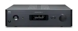
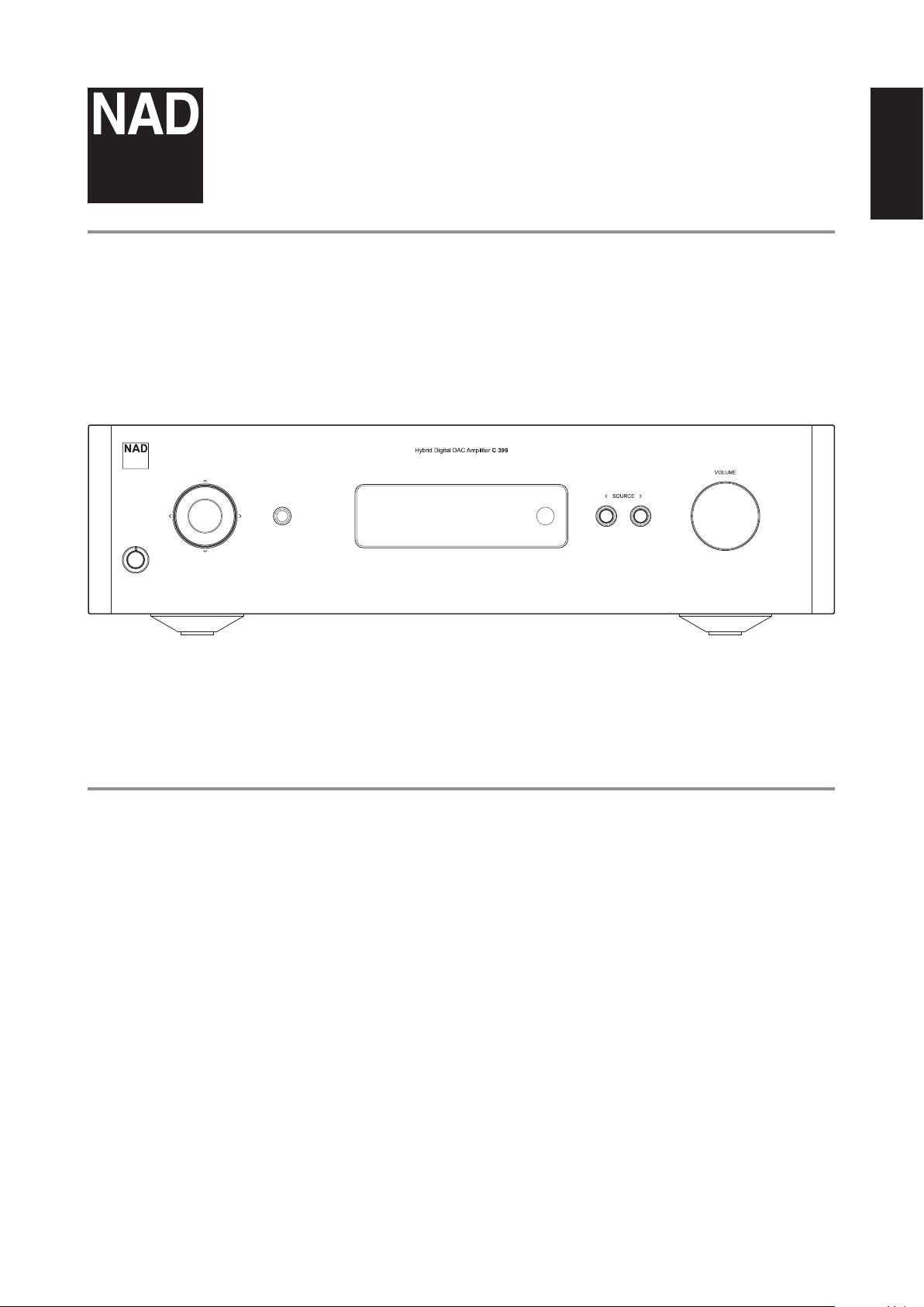
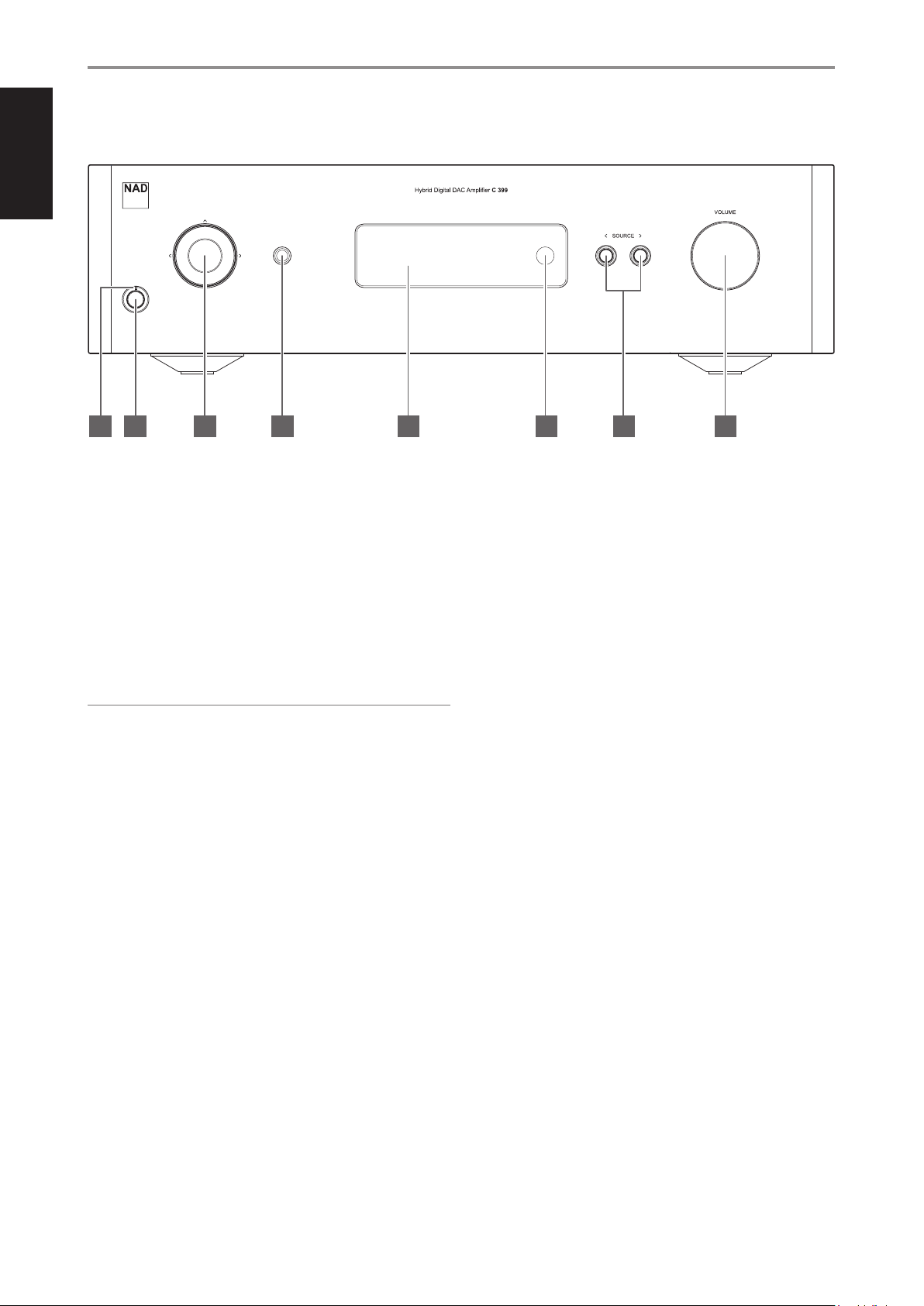
1 POWER INDICATOR
• This indicator will be amber when the C 399 is in standby mode.
• When the C 399 is powered up from standby mode, this indicator
will change from amber to blue color.
2 STANDBY BUTTON
• Press Standby button to switch ON the C 399 from standby mode.
The Power indicator will change from amber to blue color.
• Pressing Standby button again switches back C 399 to standby
mode. The Power indicator will change from blue to amber color.
• The Standby button cannot activate the C 399 if the rear panel
POWER switch is o.
IMPORTANT NOTES
Conditions for Standby button to activate
a Connect the plug of the supplied power cord to a mains power
outlet while ensuring that the other end of the power cord is rmly
connected to C 399’s AC Mains input socket.
b The rear panel POWER switch must be set to ON.
3 NAVIGATION AND ENTER BUTTONS
• The navigation [d/f/a/s] and [ENTER] buttons are used to go
through menu options and selections.
• Use [d/f/a/s] to go up, down, left or right the given options or
selections.
• The middle round button is designated as [ENTER] button. This is
normally pressed to complete a selection, procedure, sequence or
other applicable functions.
4 HEADPHONES
• A 1/4” stereo jack socket is supplied for headphone listening and
will work with conventional headphones of any impedance.
• The volume, tone and balance controls are operative for
headphone listening. Use a suitable adapter to connect
headphones with other types of sockets, such as 3.5mm “personal
stereo” jack plugs.
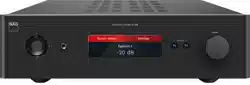
5 DISPLAY
• Visual and menu information are shown according to the selected
settings.
• The following Main menu options are selectable from the display –
Settings, Source Setup and System Info.
• Use the SR 9 remote control or front panel navigation [d/f/a/s]
and [ENTER] buttons to go through menu options and selections.
6 REMOTE SENSOR
• Point the SR 9 remote control at the remote sensor and press the
buttons.
• Do not expose the remote sensor of the C 399 to a strong light
source such as direct sunlight or illumination. If you do so, you may
not be able to operate the C 399 with the remote control.
Distance: About 23ft (7m) from the front of the remote sensor.
Angle: About 30° in each direction of the front of the remote sensor.
7 a SOURCE s
• Press a SOURCE or SOURCE s to select Sources.
8 VOLUME
• The VOLUME control adjusts the overall loudness of the signal sent
to the loudspeakers. The Volume control is characterized by perfect
signal tracking and channel balance. It provides a highly linear and
low noise operation.
• Turn clockwise to increase the volume level and counterclockwise
to lower it.
• The default volume level is -20dB.
• Volume level will wake up and reset to the -20 dB default setting if
the unit goes to standby mode with a variable volume level higher
than -20 dB. However, if volume level is lower than -20 dB when
the unit goes to standby mode, that level setting will be preserved
when the unit wakes up.
IDENTIFICATION OF CONTROLS
FRONT PANEL
6
© NAD C 399
7654321 8
ENGLISH
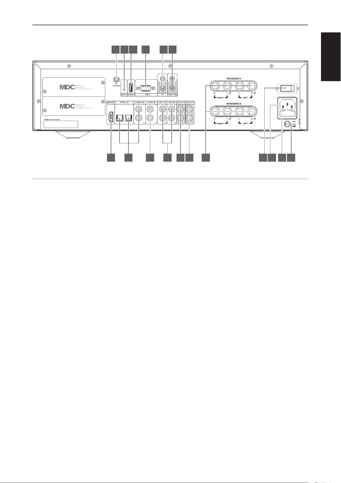
1 BLUETOOTH ANTENNA TERMINAL
• Install supplied Bluetooth antenna to this Bluetooth antenna
terminal.
2 RESET
• It is not recommended to use RESET button unless necessary. Use
the RESET function button when everything else fails and the unit
may not be able to recover.
• Switched OFF the rear panel POWER switch. Press and hold the
RESET button and switch ON the rear panel POWER switch. There
will be two scenarios as you hold on to the RESET button
- Hold on to the RESET for less than 30 seconds: Initiate chassis
USB stick Upgrade or BluOS MDC card upgrade if a BluOS card
is installed.
- Hold on to the RESET for more than 30 seconds: Initiate chassis
factory reset.
• Contact your nearest service center for further guidance on how to
use RESET function button.
3 SERVICE
• Use for USB rmware update. Contact your nearest service center
for rmware update guidance.
4 RS 232
NAD is a certied partner of AMX and Crestron and fully supports
these external devices. Check out the NAD website for information
about AMX and Crestron compatibility with NAD. See your NAD audio
specialist for more information.
• Connect this interface using RS-232 serial cable (not supplied) to
any Windows compatible PC to allow remote control of the C 399
via compatible external controllers.
• Refer to the NAD website for information about RS232 Protocol
documents and PC interface program.
5 IR IN/IR OUT
• These mini-jacks accept and output remote-controlled codes in
electrical format, using industry-standard protocols, for use with
“IR-repeater” and multi-room systems and related technologies.
• All NAD products with IR IN/IR OUT features are fully compatible
with the C 399. For non-NAD models, please check with your other
product’s service specialists with respect to their compatibility to
the C 399’s IR features.
IR IN
• This input is connected to the output of an IR (infrared) repeater
(Xantech or similar) or the IR output of another compatible device
to allow control of the C 399 from a remote location.
IR OUT
• Connect IR OUT to the IR IN jack of a compatible device.
• Command and control the linked compatible device by directing its
own remote control to C 399’s infrared receiver.
6 +12V TRIGGER
+12V TRIGGER OUT
• The +12V TRIGGER OUT is used for controlling external equipment
equipped with a +12V trigger input.
• Connect this +12V TRIGGER OUT to the other equipment’s
corresponding +12V DC input jack using a mono cable with 3.5mm
male plug.
• This output will be 12V when the C 399 is ON and 0V when it is
either OFF or in standby mode.
IDENTIFICATION OF CONTROLS
REAR PANEL
7
© NAD C 399
100-120V/220-240V 50/60Hz
1615
6
14
5
10 11 12 13
4
9
3
8
2
7
1
17
ATTENTION!
Please ensure that the C 399 is powered o or unplugged from the mains power outlet before making any connections. It is also advisable to power down
or unplug all associated components while making or breaking any signal or AC power connections.

ENGLISH
IDENTIFICATION OF CONTROLS
REAR PANEL
8
+12V TRIGGER IN
• With this input triggered by a 12V DC supply, the C 399 can be
switched ON remotely from standby mode by compatible devices
such as ampliers, preampliers, receivers, etc. If the 12V DC supply
is cut o, the C 399 will return to standby mode.
• Connect this +12V Trigger input to the remote device’s
corresponding +12V DC output jack using a mono cable with
3.5mm male plug. The controlling device must be equipped with a
+12V trigger output to use this feature.
NOTE
If there is a stereo jack connected to +12V TRIGGER IN, the C 399 cannot
be powered ON/OFF using the front panel Standby button or SR 9’s ON/
OFF buttons. The stereo jack has to be unplugged to resume normal
powering up of the unit via front panel Standby button or SR 9’s ON/OFF
buttons.
7 HDMI ARC/eARC
• Connect to TV that supports HDMI Control (CEC) and Audio
Return Channel (ARC) or Enhanced Audio Return Channel (eARC)
functions. HDMI CEC, ARC or eARC functions are possible if external
devices that also support these features are interconnected with
C 399 via HDMI connection.
• Use HDMI cable to connect HDMI ARC/eARC to corresponding
HDMI ARC/eARC port of TV. Use HDMI cable that has Ultra High
Speed HDMI Certication Label to enjoy support for larger
bandwidth and high bitrate format.
• With ARC/eARC connection established, C 399 will output audio
signal from TV.
IMPORTANT
• Ensure that the audio setting/format of ARC/eARC-connected devices to
C 399 is set to PCM only.
• Only audio output signal from TV is supported by HDMI ARC/eARC port.
• There is no video output at HDMI ARC/eARC port of C 399.
8 OPTICAL 1-2/COAXIAL 1-2
• Connect to the corresponding optical and coaxial digital output
of sources such as CD or BD/DVD players, digital cable box, digital
tuners and other applicable components.
9 PHONO
• Input for a Moving Magnet (MM) phono cartridge only. Connect the
twin RCA-to-RCA lead from your turntable to this input if you are
using a Moving Magnet cartridge.
• If your turntable includes a ground/earth lead, it can be connected
to the Ground Terminal (refer to item 18 below).
10 LINE 1-2 IN
• Input for line level sources such as CD player, tuner or any
compatible devices. Use a twin RCA-to-RCA lead to connect the
source device’s left and right “Audio Output” to these line input
ports.
11 PRE OUT
• Use dual RCA-to-RCA cable to connect PRE-OUT to the
corresponding analog audio input of compatible devices such
as ampliers, receivers or other applicable devices. This makes it
possible to use the C 399 as a pre-amplier to such devices.
12 SUB OUT 1, 2
• Connect SUBW 1 and/or 2 to the low level input of corresponding
powered subwoofer.
• Anything below your crossover setting (accessible via BluOS
Controller App with optional MDC2 BluOS D installed) will be sent
out via SUB OUT. Default crossover setting is 80Hz.
13 SPEAKERS A, B
• The C 399 has two sets of SPEAKER connections (SPEAKERS A and
SPEAKER B) that are identical in function (parallel connection).
• Connect C 399’s Right speaker terminals marked “R +” and “R-” to
the corresponding “+” and “-“ terminals of your designated right
speaker. Repeat the same for C 399’s Left speaker terminals and
corresponding left speaker.
• Double check the speaker connections before powering up the
C 399.
IMPORTANT NOTES
• The blue terminals must never be connected to ground (earth).
• Never connect the blue terminals together or to any common ground
device.
• Do not connect the output of this amplier to any headphone adapter,
speaker switch or any device that uses common ground for left and
right channels.
14 POWER
• Supplies the AC mains power to C 399.
• When the POWER switch is set to ON position, the C 399 goes to
standby mode as shown by the amber status condition of the front
panel Power indicator.
• Press the front panel Standby button or SR 9’s remote control’s [ON]
button to switch ON the C 399 from standby mode.
• If you do not intend to use the C 399 for long periods of time (such
as when on vacation), switch o the POWER switch.
• With POWER switched o, neither the front panel Standby button
nor SR 9 remote control’s [ON] button can activate the C 399.
15 AC MAINS INPUT
• The C 399 comes supplied with two separate mains power cords.
Select the mains power cord appropriate for your region.
• Before connecting the plug to the mains power outlet, ensure that
it is rmly connected to the C 399’s AC Mains input socket.
• Always disconnect the mains power plug from the mains power
outlet before disconnecting the cable from the C 399’s AC Mains
input socket.
16 FUSE HOLDER
• Only qualied NAD service technicians can have access to this fuse
holder. Opening this fuse holder may cause damage thus voiding
the warranty of your C 399.
17 GROUND TERMINAL
• Ensure that the C 399 is plugged-in to a grounded AC wall outlet.
• If necessary, use this ground terminal to connect to ground a
phono or turntable source for PHONO input.
• If a separate earth ground is necessary, use this terminal to ground
your C 399. The C 399 can be connected to ground by connecting
a ground lead wire or similar to this terminal. After insertion, tighten
the terminal to secure the lead.

ENGLISH
MDC2 UPGRADE SLOTS
C 399 supports NAD’s MDC2 architecture. By enabling two-way
communications between the module and component, MDC2 opens up
the future for new upgrades.
MDC2 BLUOS-D
The optional MDC2 BluOS-D module lets listeners play
music from their favourite streaming services through
the C 399. MDC2 BluOS-D is equipped with Wi-Fi and
Ethernet and uses the acclaimed BluOS Controller app
for Android, iOS, macOS, and Windows.
Like all BluOS-enabled products, the MDC2 BluOS-D
has integrated support for dozens of streaming services
and supports Apple AirPlay 2, Spotify Connect, and Tidal
Connect. Two-way communications also enable the
MDC2 BluOS-D to stream music from sources connected
to the C 399 to BluOS-enabled components in other rooms.
The MDC2 BluOS-D comes with Dirac Live® Limited Bandwidth (20Hz –
500Hz) installed with the option for advanced users to upgrade to the
Dirac Live Full Frequency version. Dirac Live function lets you measure
your room’s acoustics using a supplied microphone and intuitive app, and
then upload correction curves to the MDC2 BluOS-D. By compensating for
acoustic anomalies in your listening environment, Dirac Live dramatically
improves bass clarity, imaging, and timbral accuracy. Thanks to its two-way
architecture, the MDC2 BluOS-D performs room correction for all sources
connected to your C 399.
IDENTIFICATION OF CONTROLS
REAR PANEL
9
ENGLISH
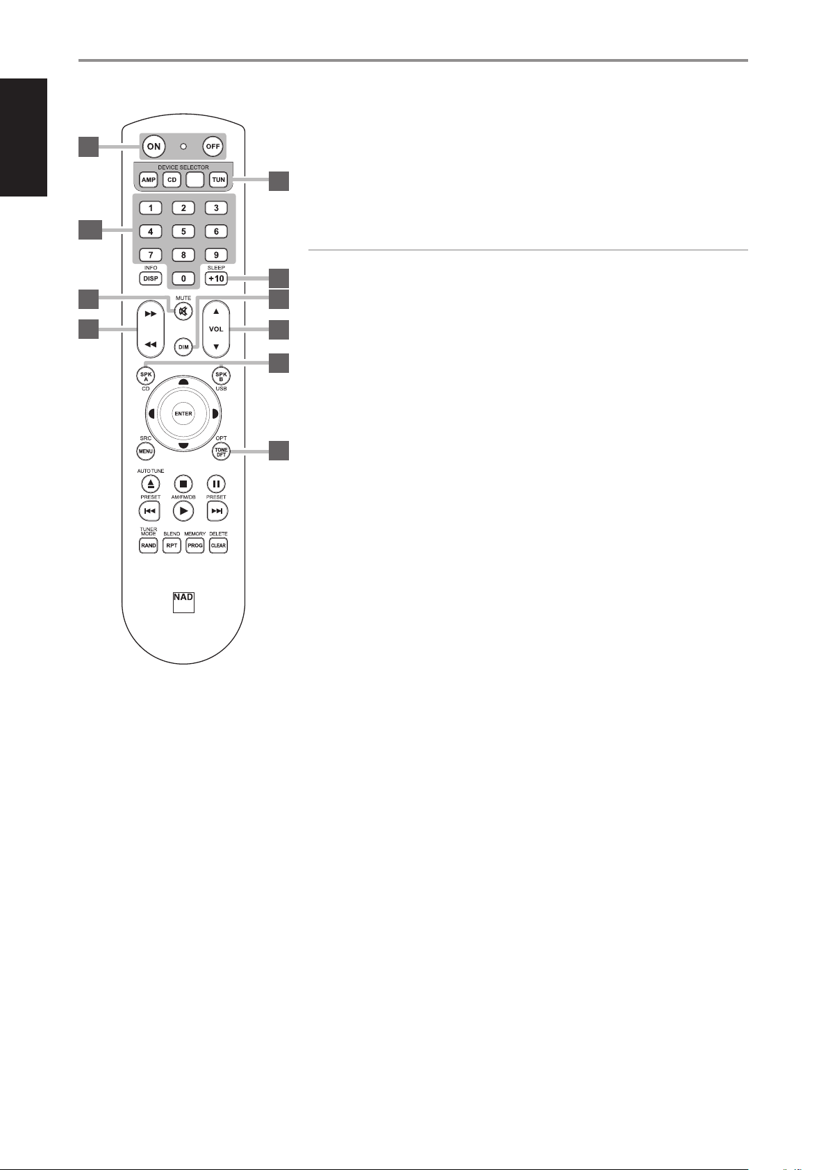
The SR 9 remote control handset handles the key functions of the C 399 as well as other NAD Stereo
Receivers, Integrated Ampliers and Preampliers. It has additional controls to remotely operate
NAD CD Players, AM/FM Tuners and dedicated AM/FM/DAB Tuners. It will operate up to a distance of
23ft (7m). Alkaline batteries are recommended for maximum operating life. Two AA batteries should
be tted in the battery compartment at the rear of the Remote Control handset. When replacing
batteries, check that they have been put in the right way round, as indicated on the base of the battery
compartment.
NOTE
The remote control handset supplied with the C 399 is of a universal NAD type, designed to operate
several NAD models. Some buttons are applicable only to specic NAD models. Contact your dealer
or NAD audio specialist for assistance.
1 POWER ON/OFF: The SR 9 remote has a separate ON and OFF button. Press ON button to switch
the unit from Standby to operating mode. Press OFF button to switch the unit to Standby mode.
2 DEVICE SELECTOR: A Device Selector button determines only what component the SR 9 will
command; it does not perform any function on the C 399. Press desired Device Selector button
for the applicable buttons to be directed to a “page” of commands relevant to the selected device.
Upon selecting a Device, you can now press the corresponding SR 9 control buttons applicable for
the selected Device.
3 INPUT SELECTORS: Refer to the corresponding labels printed in the remote control faceplate
and their respective assigned buttons to make use of these functions. Set the DEVICE SELECTOR to
“AMP” in order to gain access to these buttons.
4 NUMERIC KEYS: The numeric keys allow for direct input of tracks for CD players, and direct
channel/preset access for tuners and receivers.
5 SLEEP: Switch o specic NAD Receiver or Tuner models after a preset number of minutes. This
control button does not apply to C 399.
6 MUTE: Press the [MUTE] button to temporarily switch OFF the sound to the speakers and
headphones. MUTE mode is indicated by the Standby LED indicator ashing for NAD Integrated
Ampliers or “Mute” shown in the VFD of NAD Receivers. For C 399, “Mute” is shown in the display.
Press MUTE again to restore sound. Adjusting the volume level via the SR 9 or the front panel
volume knob will automatically release the mute function.
7 SOURCE 7/8: Toggle through the source input selections. If the optional MDC modules are
installed, the source selections will include the sources incorporated in the applicable modules.
8 DIM (for use with NAD Stereo Receiver, Tuner and CD Player): Reduce, turn o or restore
display brightness. Depending on the NAD model, the brightness of the front panel display
will vary when you toggle this button. For C 399, toggle to vary brightness level of the display -
brighter, normal or dimmer.
9 VOL [5/6]: Press [5/6] button to increase or decrease the loudness level. Release the button
when the desired level is reached. For NAD Receivers, the VFD will also show “Volume Up” or
“Volume Down” while pressing SR 9’s VOL [5/6]. For C 399, when VOL [5/6] is pressed, the dB
level shown in the display will correspondingly increase or decrease.
10 SPK A, SPK B: The [SPK A] and [SPK B] buttons engage or disengage the speakers connected
respectively to the Speakers A and Speakers B terminals. Toggle [SPK A] to switch ON or OFF the
speakers connected to the Speaker A terminals. Toggle [SPK B] to switch ON or OFF the speakers
connected to the Speaker B terminals. These control buttons do not apply to C 399.
11 TONE DFT: Tone controls are enabled or disabled by pressing this button. This control button does
not apply to C 399.
IDENTIFICATION OF CONTROLS
USING THE SR 9 REMOTE CONTROL
10
SR 9
OPT 1 OPT 2 COAX 1
COAX 2 PHONO LINE 1
LINE 2 USB BT
BLS
SCAN
TUNE
SOURCE
SCAN
TUNE
SOURCE
SCAN
TUNE
SOURCE
SCAN
TUNE
SOURCE
2
8
9
10
1
3, 4
6
7
5
11
ENGLISH
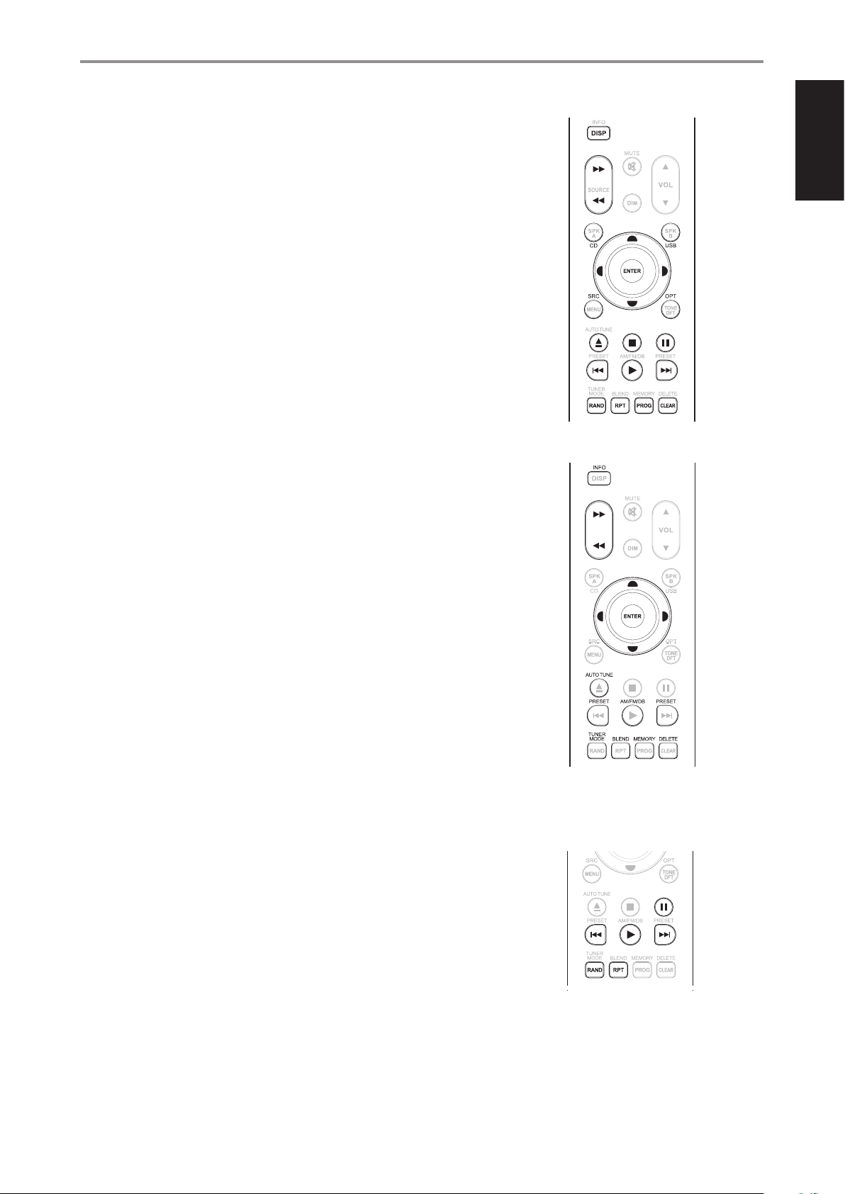
CD PLAYER CONTROL (for use with NAD CD Player): Set the DEVICE SELECTOR to “CD” in order to
gain access to these buttons. Some of the control buttons below are applicable only to specic NAD
CD Player models; check the owner’s manual of your NAD CD Player for control button compatibility.
SCAN [7/8]: Fast reverse/forward search.
[k]: Open or close disc tray.
[g]: Stop playback.
[j]: Pause playback temporarily.
[0]: Go to next track/le.
[9]: Go to beginning of current track/le or to previous track/le.
[4]: Start playback.
[A/S/D/F]: Select through folder list/Select through WMA/MP3 les.
ENTER: Select desired folder or WMA/MP3 le.
DISP: Show playback time and other display information.
RAND: Play tracks/les in random order.
RPT: Repeat track, le or whole disc.
PROG: Enter or exit program mode.
CLEAR: Delete programmed track/le.
CD: Select CD as the active source.
USB: Select USB as the active source.
OPT: Select optical input as the active source.
SRC: Toggle to select desired SRC mode.
TUNER CONTROL (for use with NAD AM/FM/DAB Tuner): Set the DEVICE SELECTOR to “TUN” in
order to gain access to these buttons. Refer to the corresponding labels printed in the remote control
faceplate and their respective assigned buttons to make use of these functions. Some of the control
buttons below are applicable only to specic NAD Receiver or Tuner models; check the owner’s
manual of your NAD Receiver or Tuner for control button compatibility.
AUTO TUNE: In DAB mode, press this button to automatically scan all available local stations.
TUNE [7/8] or [A/S]: Step up or down between AM or FM frequencies.
PRESET [9/0] or [D/F]: Step up or down between stored radio presets.
AM/FM/DAB: Select AM, FM, DAB or XM band (if applicable).
TUNER MODE: In FM mode, toggle between “FM Mute On” and “FM Mute O”. In DAB mode,
pressing this button will activate Dynamic Range Control (DRC), Station Order or other applicable
DAB menu options.
BLEND: Engage or disengage BLEND feature.
MEMORY: Save current station into preset memory.
DELETE: Press and hold for about 2 seconds and the selected preset memory is erased.
[A/S]: In DAB mode, in combination with TUNER MODE or other compatible buttons, toggle
to select through DAB feature options like Dynamic Range Control, Station Order and other
appropriate DAB options.
ENTER: In AM/FM mode, toggle to select Preset or Tune mode. In DAB mode, press and hold to
check signal strength.
INFO: Repeatedly pressing this button will show information as supplied by the current radio
station. The applicable display contents include related DAB display information and RDS broadcast
data.
BluOS PLAYBACK CONTROLS
Set DEVICE SELECTOR to BLS and use the following control buttons for BluOS playback. Some control
buttons below may not be applicable.
[4]: Resume playback from pause mode. When applicable, toggle to play or pause playback.
[j]: Pause current playback.
[9]: Skip back to the beginning of current song.
[0]: Skip forward to the next song.
REPEAT: Repeat song, playlist, all or repeat o. Refer to BluOS controller app to see repeat mode
indicators.
RANDOM: Play songs/playlist in random order
IDENTIFICATION OF CONTROLS
USING THE SR 9 REMOTE CONTROL
11
SR 9
OPT 1 OPT 2 COAX 1
COAX 2 PHONO LINE 1
LINE 2 USB BT
BLS
SCAN
TUNE
SOURCE
SCAN
TUNE
SOURCE
SCAN
TUNE
SOURCE
SCAN
TUNE
SOURCE
SR 9
OPT 1 OPT 2 COAX 1
COAX 2 PHONO LINE 1
LINE 2 USB BT
BLS
SCAN
TUNE
SOURCE
SCAN
TUNE
SOURCE
SCAN
TUNE
SOURCE
SCAN
TUNE
SOURCE
SR 9
OPT 1 OPT 2 COAX 1
COAX 2 PHONO LINE 1
LINE 2 USB BT
BLS
SCAN
TUNE
SOURCE
SCAN
TUNE
SOURCE
SCAN
TUNE
SOURCE
SCAN
TUNE
SOURCE

ENGLISH
USING THE SR 9 REMOTE CONTROL LIBRARY
The SR 9 can store a dierent library of default NAD codes for each of its DEVICE SELECTOR “pages.” If
the original default library does not control your NAD CD player, DVD player or other components,
follow the procedure below to change the library code. Refer as well to the table below for a list of
applicable NAD Library Codes with their corresponding NAD models.
LOAD ANOTHER LIBRARY CODE
Example: Load NAD DVD Player T 517 library codes to SR 9’s “CD” device.
1 Press and hold [CD] in the DEVICE SELECTOR section of SR 9.
2 While holding down the device button (CD), press “2” and “2” using SR 9’s numeric buttons. “22” is
the corresponding library code for T 517.
3 Press [ENTER] while still holding down the device button (CD). The CD device selector will ash
once to indicate that the library input is successful. Both the device selector button (CD) and
[ENTER] can now be released.
RESET THE SR 9 TO ITS DEFAULT SETTINGS
The SR 9 can be restored to its factory settings, including default libraries, by the following procedures
1 Press and hold [ON] and [DELETE/CLEAR] buttons for about 10 seconds until the AMP device
button lights up.
2 Within two seconds of the AMP device button lighting up, release both buttons. If the reset mode
is successful, the [CD] device button will ash twice.
TABLE OF LIBRARY CODES APPLICABLE TO SR 9 REMOTE CONTROL
LIBRARY CODE NAD PRODUCT DESCRIPTION
10 Default library for “AMP” page
11 Zone 2
12 Default library for “AMP” page without discrete ON/OFF (toggle ON/OFF) buttons
20 Default library for “CD” page; C 515BEE, C 545BEE, C 565BEE
21 T 535, T 585, M55, DVD section of L 54, VISO TWO, VISO FIVE
22 T 513, T 514, T 515, T 517
23 T 587
31 IPD 2
40
Default library for “TUN” page; Tuner section of C 725BEE,
T 175, T 737, T 747, T 755, T 765, T 775, T 785
41 C 422, C 425
42 C 445
50 DAC
NOTE
The SR 9 may not necessarily contain all the control buttons applicable for the above-mentioned
NAD products. Use the prescribed remote control of the specic NAD product for a full complement
of the applicable remote control buttons.
IDENTIFICATION OF CONTROLS
USING THE SR 9 REMOTE CONTROL
12
ENGLISH
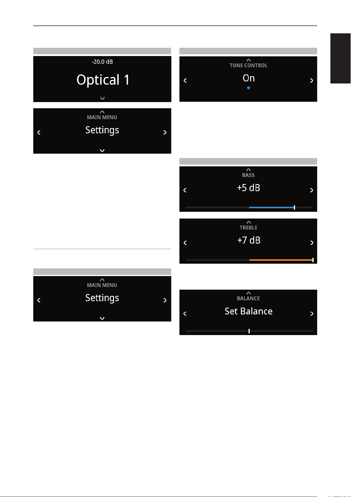
ACCESS MAIN MENU
Press front panel [f] button once for the Main Menu options to appear in
the display. Use front panel a or s button to select through the Main Menu
options – Settings, Source Setup and System Info.
NAVIGATING THE MENU OPTIONS AND MAKING CHANGES
Navigate through the menu options using the front panel buttons or
corresponding SR 9 buttons.
1 Press [f] to select a menu item.
2 Repeatedly press [a/s] to scroll through menu choices, options or
selections.
3 Press [d] or [ENTER] to select or save current selection or option and at
the same time exit or return to the previous menu.
NOTE
Menu option will remain displayed and will only turn o or default to
current Source after 1 minute of non-user interface.
SETTINGS
The “Settings” main menu allows the conguration of the following
features:
• Tone Control
• Treble
• Bass
• Balance
• Auto Standby
• Bluetooth Mode
• Network Standby
• CEC Power
• IR Channel
• Brightness
• Temporary Display
• Speaker
• Volume Display Mode
TONE CONTROL
Tone control allows the boosting or reduction of particular audio frequencies.
The tone control levels, Bass and Treble, can be turned on or o.
• On: Tone control levels are active. At Tone Controls On, Bass and
Treble control levels are available for conguration.
• O: Tone controls levels are bypassed. At Tone Controls O, Bass
and Treble control levels become unavailable or turned o from the
Settings menu.
BASS, TREBLE, BALANCE
Bass and Treble controls only aect the low bass and high treble leaving
the critical midrange frequencies free of coloration.
• Use [a/s] to boost or cut Bass or Treble levels within ±7 dB range.
Balance control adjusts the relative levels of the left and right channels.
• Press [s] to shift the balance to the right or [a] to shift the balance to
the left. Use [a/s] also to recover or even out the balance levels.
• The center level setting provides equal level to the left and right
channels.
OPERATION
USING C 399
13
ENGLISH
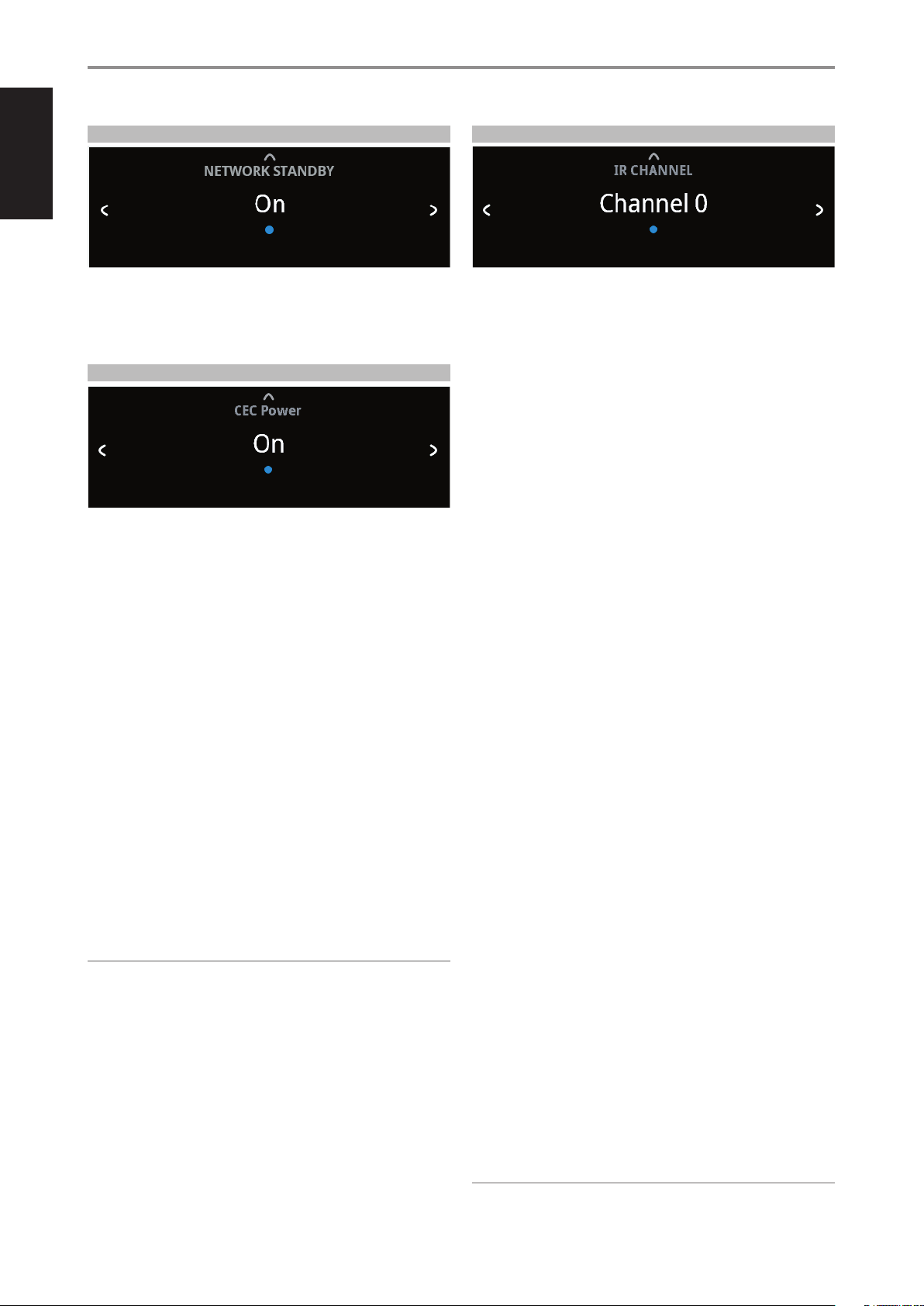
NETWORK STANDBY
Network Standby mode maintains network connection at standby mode
with reduced system performance level.
On: Network connection is maintained at standby mode.
O: Network connection is disconnected at standby mode.
CEC POWER
HDMI CONTROL CEC
Consumer Electronics Control (CEC) is a set of commands that utilizes
HDMI’s two- way communication to allow for single remote control of any
CEC-enabled devices connected with HDMI. A CEC command will trigger
the necessary commands over HDMI for an entire system to auto-congure
itself to respond to the command.
CEC Power O: C 399 cannot be powered up or sent to standby mode
by a CEC-enabled device.
CEC Power On: CEC-enabled device can power ON/OFF the C 399.
HDMI ENHANCED AUDIO RETURN CHANNEL eARC
Enhanced Audio Return Channel (eARC) is an advancement over the
previous Audio Return Channel (ARC). eARC simplies connectivity and
provides greater ease of use for multiple components discovery and audio
optimization.
eARC enables the audio to a TV that originates from cable, satellite,
streaming or source devices to be sent to C 399 through a single HDMI
cable. This ensures the simplicity of connectivity and that the original audio
can be experienced. HDMI eARC works with HDMI High Speed Cables with
Ethernet and the new Ultra High Speed HDMI Cable.
eARC is the default mode for C 399 and will fallback to ARC if no eARC
connection happens.
IMPORTANT!
• Ensure that the audio setting/format of eARC/ARC-connected devices to
C399 is set to PCM only.
• Only audio output signal from a connected TV is supported by C399’s
HDMI eARC port.
IR CHANNEL
The C 399 has the capability to operate via Alternate IR channel. This is
useful if you have two NAD products that can be operated by similar
remote control commands. With alternate IR Channel, two dierent NAD
products can be controlled independently in the same zone by setting
each one to a dierent IR channel.
IR Channel Assignment
The C 399 and the SR 9 remote control must be set to the same channel.
To change the IR Channel on the C 399
While at IR Channel menu, use [a/s] to select through Channel 0 to
Channel7. Stop at the preferred IR Channel setting and press [d] to
complete the selection. C 399 IR Channel is defaulted to Channel 0.
To change the IR Channel on the SR 9 remote control
• Include a channel number before the library code. For SR 9, library code
“10” is the default library table for “AMP” device. To select this “AMP”
library table for Channel 0, retain the library code “10” (or “010”).
• If you want to load the “AMP” library table on “Channel 1” prex the
library code with “1” to indicate association with “Channel 1”. Load then
the “AMP” library table using the code “110”. Repeat the same for MP
(130) and TUNER (140).
SAMPLE SETUP OF TWO NAD PRODUCTS ON THE SAME ZONE
C 399 and T758 are both defaulted to Channel 0. If [OFF] button is pressed
on the SR9 remote control (or AVR 4 remote control for the T 758), both
products will go to standby mode. Press [ON] and both products will power
up from standby mode.
To prevent both products from simultaneously going in and out of standby
mode along with other common commands, set each one to a dierent
IR channel. In this setup, we will keep T 758 and AVR 4 remote control
defaulted to “Channel 0”. As for C 399, we will assign it to “Channel 1”; the
same applies to SR 9.
Set C 399 and SR 9 to “Channel 1” via the following procedure.
C 399
While at “IR Channel” menu, use the [a/s] to go to “Channel 1” setting. Press
[d] to select “Channel 1”.
SR 9
• Press and hold [AMP] in the DEVICE SELECTOR section of the SR 9.
• While holding down the device button [AMP], press “1”, “1” and “0” using
SR 9’s numeric buttons.
• Press [ENTER] while still holding down the device button [AMP]. The
AMP device selector will ash once to indicate that the library input is
successful.
With both C 399 and SR 9 set to “Channel 1”, the C 399 can now be
remotely controlled independent of the T 758.
NOTE
Performing Factory Reset for C 399 or SR 9 will restore their respective IR
channel setting to “Channel 0”.
OPERATION
USING C 399
14
ENGLISH
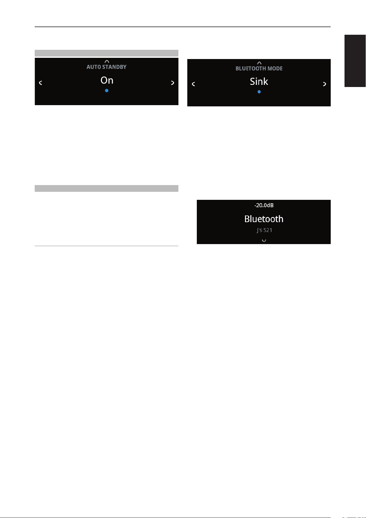
AUTO STANDBY
Auto Standby feature is an integral feature of C 399 that conforms to
European ecodesign regulations. The C 399 can be setup to automatically
go to standby mode if there is no user interface interaction and no active
source input within 20 minutes.
On: C 399 switches to standby mode at lowest power consumption
(less than 0.5W) if there is no user interface interaction and no active
source input within 20 minutes.
O: C 399 remains at operating mode even if there is no user interface
interaction and no active source within 20 minutes.
BLUETOOTH MODE
Bluetooth Mode denes the two roles of the C 399 as either a Bluetooth
Sink or a Bluetooth Source.
Sink: Audio stream is received from a Source on the same Bluetooth
network environment.
Source: Audio is streamed or sent to another device (Sink) on the same
Bluetooth network environment.
IMPORTANT!
1 Bluetooth Mode option is not available if the optional MDC2 BluOS-D is
installed.
2 With no MDC2 BluOS-D installed and “Auto Sense” setting of Bluetooth
source set to “On”, C 399 will go to Network Standby mode under the
following condition.
• With a Bluetooth device connected or disconnected, C 399 will go to
Network Standby mode if there is no user interface interaction and
no active source input within 20 minutes.
C 399 will wake up from Network Standby mode by pressing front panel
Standby button or “OFF” button of SR9 remote control or playback of
Bluetooth connected device.
Power consumption at Network Standby mode is 0.6W.
3 With no MDC2 BluOS-D installed and “Auto Sense” setting of Bluetooth
source set to “O”, C 399 will go to Standby mode if there is no user
interface interaction and no active source input within 20 minutes.
C 399 AS A BLUETOOTH SINK
Set “Bluetooth Mode” to “Sink”. Initiate pairing of your Bluetooth device with
C 399 by following below procedure.
1 Ensure that the Bluetooth antenna is connected to the BT antenna
terminal at the rear panel.
2 Using your iOS or Android device, go to Settings – Bluetooth and then
scan for Bluetooth devices. Select the unique device ID (example, C399BT)
of your C 399 as listed or selectable in the device list of your Bluetooth
settings. Pair or connect your C 399 and the Bluetooth device.
3 Upon successful pairing of your Bluetooth device and the C 399, front
panel display will show the connected Bluetooth device ID (J’s S21 in
this example).
OPERATION
USING C 399
15
ENGLISH
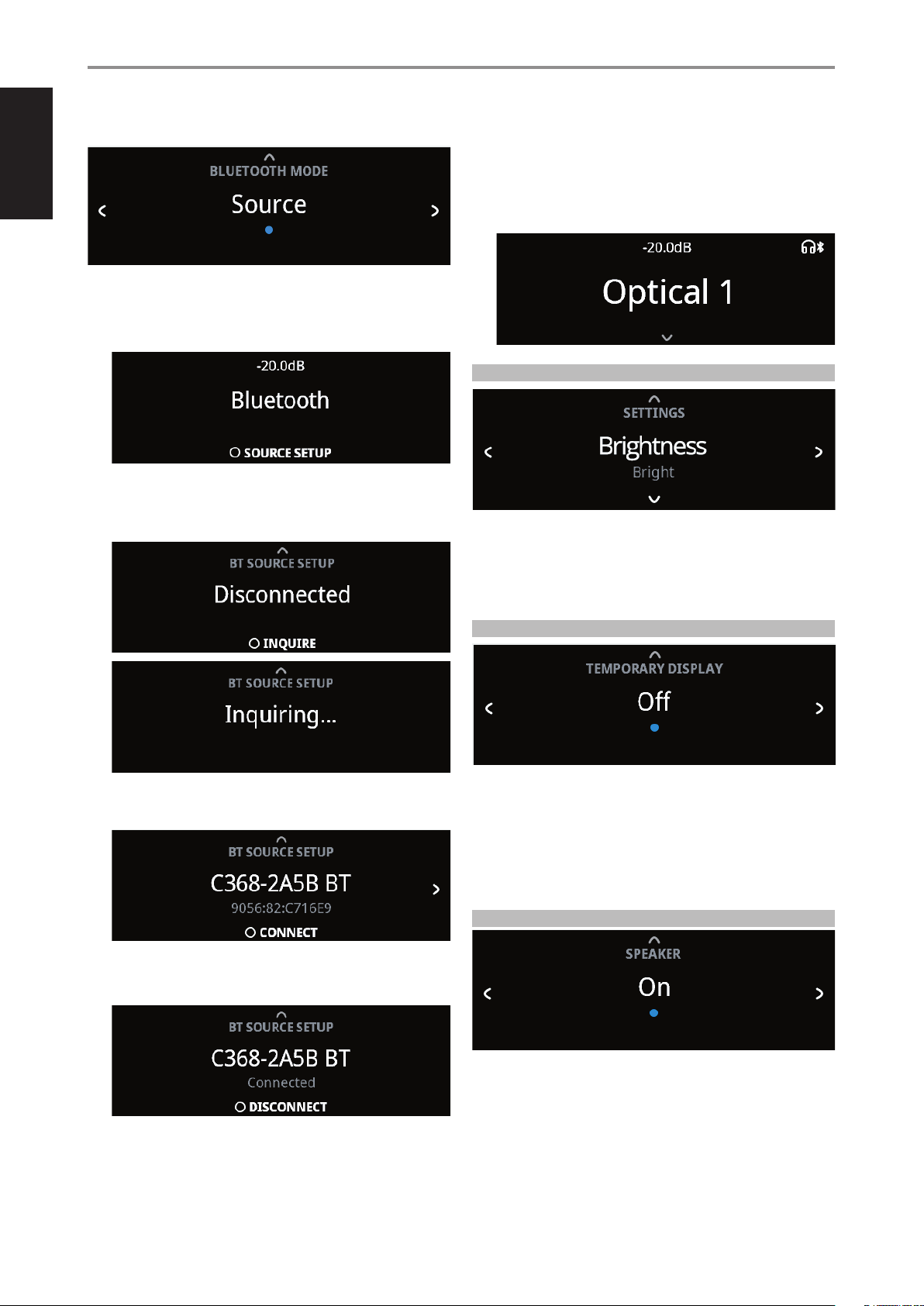
C 399 AS A BLUETOOTH SOURCE
Set “Bluetooth Mode” to “Source”. Ensure that the Bluetooth antenna is
connected to the BT antenna terminal at the rear panel.
1 While at Bluetooth Source Mode, press ENTER to select “Source Setup”.
2 “Disconnected” will appear in the display. Press ENTER to initiate inquiry
(INQUIRE). The unit searches for available Bluetooth devices within the
same Bluetooth network environment.
3 Toggle a/s to select through available Bluetooth sources. Press to
connect and select preferred Bluetooth Source.
If you would like to disconnect from current Bluetooth device, press
ENTER to select DISCONNECT. Repeat steps 2 to 3 again to select and
connect to another Bluetooth device.
4 Having settled on a Bluetooth Source device, toggle a SOURCE s to
select the source media you would like streamed to the connected
Bluetooth device. For example, if you want to stream audio from
OPTICAL 1, select OPTICAL 1 as the active source. Note the Headphone
and Bluetooth icons in the front panel display as indication that you are
at Bluetooth Source Mode.
BRIGHTNESS
BRIGHTNESS function makes it possible to adjust the brightness level of the
front panel display.
Normal: Display brightness level is normal.
Bright: Display is at its brightest level or above normal brightness level.
Dim: Display is dimmed or below normal brightness level.
TEMPORARY DISPLAY
Temporary Display feature enables the display to be turned o temporarily
after 30 seconds of non-user interface.
On: Display is turned o temporarily after 30 seconds of non- user
interface. The Power Indicator LED is also turned o at the same time.
Display and Power Indicator LED are activated once user interface is
initiated.
O: Display remains illuminated.
SPEAKER
Select “On” to enable speakers or “O” to disable speakers.
OPERATION
USING C 399
16
ENGLISH
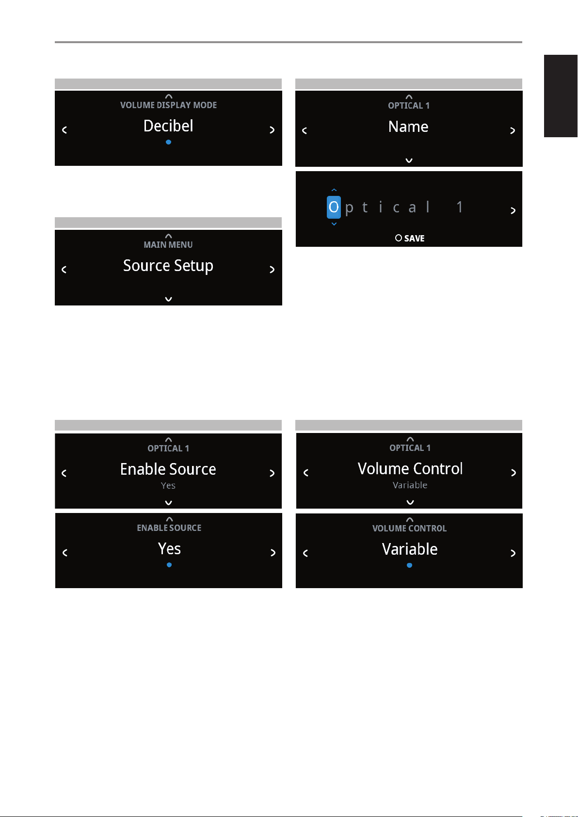
VOLUME DISPLAY MODE
Volume Display Mode gives the user two options on how to display
Volume level. Use a or s to select between “Decibel” and “Percent” Volume
display mode.
SOURCE SETUP
Source Setup has the following menu items:
• Enable Source
• Name
• Volume Control
• Auto Sense
• Analog Bypass
• Analog Gain
At Source Setup menu, select the particular Source you want to congure.
ENABLE SOURCE
One can enable/disable a Source via this option. This is particularly useful if
only few Sources are used thereby bypassing unused sources.
On: Enable selected Source.
O: Disable selected Source.
NAME
A new Name maybe assigned to a Source label. For example, if your BD
player is attached to “Optical 1”, it is possible to rename “Optical 1”to “BD
Player”.
In order to rename the Source label, select “Name” parameter.
1 While at the selected Source, for example “Optical 1”, press ENTER to
select “EDIT”.
2 Use [f /d ] to pick through the alphanumeric selections.
3 Press [s] to move to the next character and at the same time save the
changes done on the current character. The name can be as long as
fourteen characters.
4 Repeat steps 1 and 2 for each character in sequence.
5 Complete the renaming process by pressing [ENTER button again to
save the new source’s input name. The new Name will be shown in the
display.
VOLUME CONTROL
Volume control can be set to either Variable or Fixed level.
Variable: Volume level is adjusted using the volume knob or SR 9’s
[VOL5/6] buttons.
OPERATION
USING C 399
17
ENGLISH
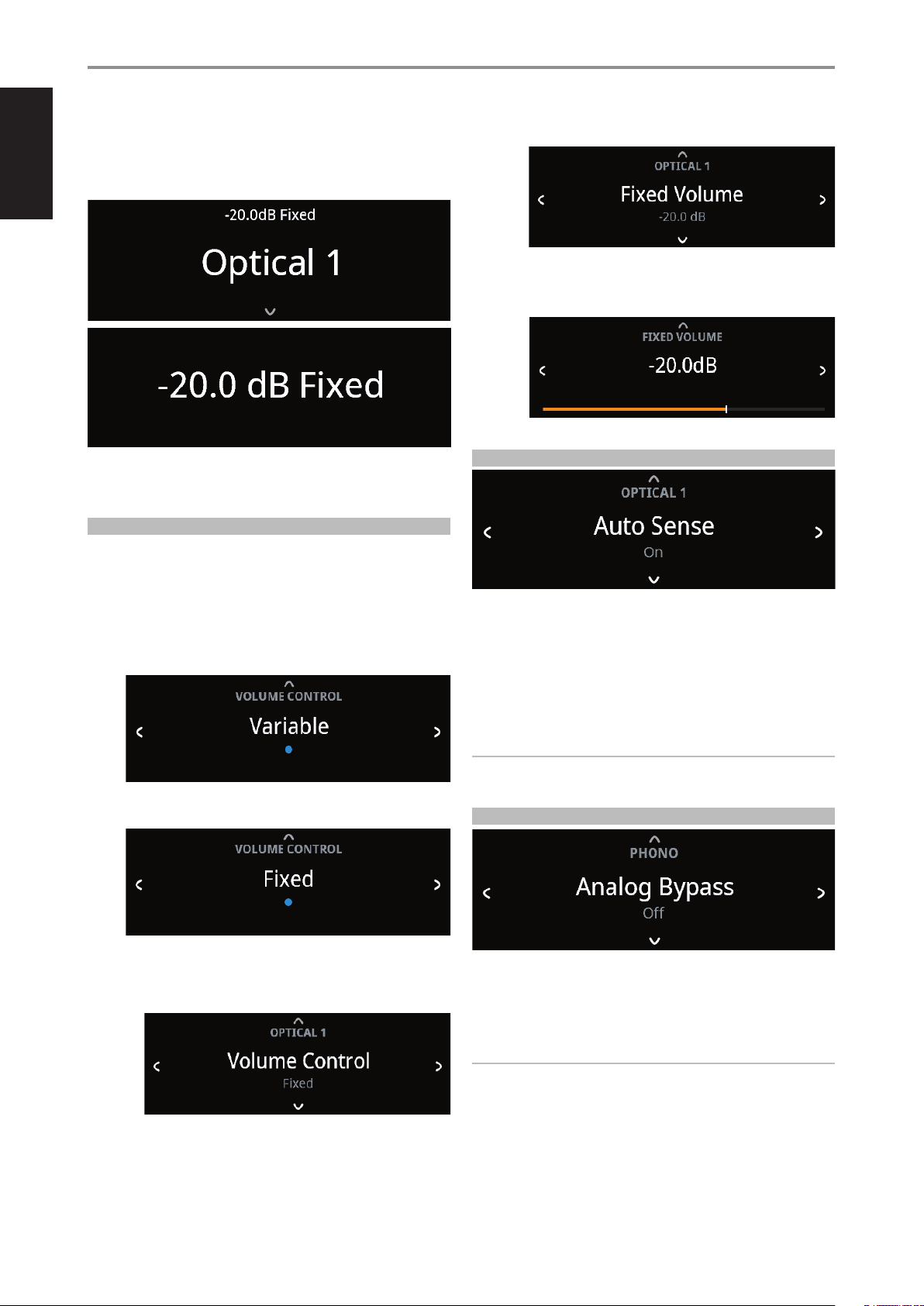
Fixed: Output level is xed and the C 399’s Volume Control is bypassed.
This feature is sometimes referred to as “Cinema Bypass” because it allows
the C 399 to be used for the front channels of a surround sound system by
relegating the volume control function to the surround processor.
At Fixed volume level setting, front panel display will show “xx.x dB Fixed” as
the volume control is adjusted.
HOW TO NAVIGATE VOLUME CONTROL LEVEL SETTING
A While at “Volume Control” menu, press [f].
B Use front panel [a/s] or SR 9’s [A/S] buttons to toggle between
“Variable” and “Fixed” level options.
1 While at “Variable” option, use front panel [d] or SR 9’s [D] button
to select “Variable” level and return to “Source Setup” menu
selections.
2 While at “Fixed” option, use front panel [d] or SR 9’s [D] button to
select “Fixed” level and return to “Source Setup” menu selections.
a With “Fixed” level selected and back to “Source Setup” menu
selections, use front panel [a/s] or SR 9’s [A/S] buttons to go
“Fixed Volume” option. “Fixed Volume” manifests among “Source
Setup” options only if “Fixed” is the selected “Volume Control” level.
b Use [f] button to go to Fixed Volume level setting.
c Use front panel [a/s] or SR 9’s [A/S] buttons to set preferred
dB level setting. Then, use front panel [d] or SR 9’s [D] button
to save dB level selection and exit Fixed Volume setup mode.
AUTO SENSE
Auto Sense can be setup for each Source. Auto Sense feature enables the
designated Source to wake up from standby mode when an active source
is detected from the particular Source’s input.
On: Unit wakes up to the designated Source from standby mode when
an active source is detected from the particular Source’s input.
O: Unit does not wake up to the designated Source from standby
mode even if it is triggered by an active source.
NOTES
• Auto Sense is not applicable for Phono and BluOS (if installed) sources.
• Auto Standby must be set to ON for Auto Sense to work.
ANALOG BYPASS
All analog signals remain in the analog domain without analog-to-digital
conversions.
On: DSP circuitry is bypassed but full tone control functions remain.
O: Analog bypass feature is turned o.
NOTE
Analog Bypass is applicable only for Phono, Line 1 and Line 2 sources.
OPERATION
USING C 399
18
ENGLISH
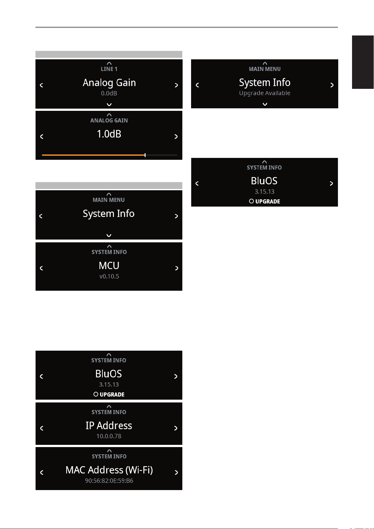
ANALOG GAIN
• Use front panel [a/s] or SR 9’s [A/S] buttons to set preferred Analog
Gain level.
SYSTEM INFO
“System Info” displays information about current MCU, LCD and FPGA
rmware versions.
Use [a/s] to toggle through the corresponding information.
If the optional MDC2 BluOS D is installed, the BluOS rmware version, IP
Address, MAC Address (Ethernet) and MAC Address (Wi-Fi) information are
also shown.
UPGRADE AVAILABLE
With the optional MDC2 BluOS D installed and C 399 connected to internet,
“Upgrade Available” will be shown if a software upgrade is available.
If “Upgrade Available” is shown, use [f] to go to BluOS upgrade menu.
Press [ENTER] to initiate upgrade mode. Internet software upgrade will
proceed automatically.
OPERATION
USING C 399
19

ENGLISH
All specs are measured according to IHF 202 CEA 490-AR-2008 standard. THD is measured using AP AUX 0025 passive lter and AES 17 active lter.
PREAMPLIFIER SECTION
LINE INPUT, PRE-OUT (Analog bypass on)
THD (20 Hz – 20 kHz) <0.002 % at 2 V out
Signal-to-Noise Ratio >106 dB (IHF; A-weighted, ref. 500 mV out, unity gain)
Channel separation >100 dB (1 kHz)
>90 dB (10 kHz)
Input impedance (R and C) 56 kohms + 100 pF
Maximum input signal >4.6 Vrms (ref. 0.1 % THD)
Output impedance Source Z + 320 ohms
Input sensitivity 65 mV (ref. 500 mV out, Volume maximum)
Frequency response ±0.3 dB (20 Hz - 20 kHz)
Maximum voltage output -IHF load >5 V (ref. 0.1 % THD)
PHONO INPUT, PRE-OUT (Analog bypass on)
THD (20 Hz – 20 kHz) <0.01 % at 2 V out
Signal-to-Noise Ratio >84 dB (200 ohms source; A-weighted, ref. 500 mV out)
Input Impedance (R and C) 46 kohms/100 pF
Input sensitivity 1.08 mV (ref. 500 mV out, Volume maximum)
Frequency response* ±0.3 dB (20 Hz - 20 kHz)
Maximum input signal at 1kHz >80 mVrms (ref. 0.1 % THD)
LINE INPUT, HEADPHONE OUT (Analog bypass on)
THD (20 Hz – 20 kHz) <0.005 % at 1 V out
Signal-to-Noise Ratio >107 dB (32 ohms loads; A-WTD, ref. 1 V out, unity gain
Frequency response ±0.3 dB (20 Hz - 20 kHz)
Channel separation >62 dB at 1 kHz
Output impedance 2.2 ohms
GENERAL SPECIFICATIONS
LINE IN, SPEAKER OUT (Analog bypass on)
Continuous output power into 8 ohms and 4 ohms 180 W (ref. 20 Hz-20 kHz at rated THD, both channels driven)
THD (20 Hz – 20 kHz) <0.02% (250 mW to 180 W, 8 ohms and 4 ohms)
Signal-to-Noise Ratio >95 dB (A-weighted, 500 mV input, ref. 1 W out in 8 ohms)
Clipping power >210 W (at 1 kHz 0.1 % THD)
IHF dynamic power 8 ohms: 217 W
4 ohms: 400 W
2 ohms: 505 W
Peak output current >26 A (in 1 ohm, 1 ms)
Damping factor >150 (ref. 8 ohms, 20 Hz to 6.5 kHz)
Frequency response ±0.3 dB (20 Hz - 20 kHz)
Channel separation >90 dB (1 kHz)
>75 dB (10 kHz)
Input sensitivity (for 180 W in 8 ohms) Line In: 201 mV
Digital In: 10.25% FS
Supports bit rate/sample rate up to 24 bit/192 kHz
Frequency band 2.402 G- 2.480 G
Maximum transmit power (dBm) 7 dBm ± 2 dBm
Network standby power 0.6 W
DIMENSION AND WEIGHT
Gross dimensions (W x H x D) ** 435 x 120 x 390 mm
17 ⁄ x 4 ¾ x 15 ⁄ inches
Net weight 10.1 kg (22.3 lbs)
Shipping weight 12.6 kg (27.8 lbs)
* The RIAA response is consistent with a pre-emphasis that is rolled off at 50 kHz by a second order filter, such as used in Neumann cutting lathes.
** Gross dimension includes feet, volume knob and extended rear panel terminals.
Specifications are subject to change without notice. For updated documentation and features, please check out www.NADelectronics.com for the latest information about C 399.
REFERENCE
SPECIFICATIONS
20

ENGLISH
21

www.NADelectronics.com
©2021 NAD ELECTRONICS INTERNATIONAL
A DIVISION OF LENBROOK INDUSTRIES LIMITED
All rights reserved. NAD and the NAD logo are trademarks of NAD Electronics International, a division of Lenbrook Industries Limited.
No part of this publication may be reproduced, stored or transmitted in any form without the written permission of NAD Electronics International.
While every effort has been made to ensure the contents are accurate at the time of publication, features and specifications may be subject to change without prior notice.
C399OMENV12 NOV 2021