Safety ,, Assembly ,, Operation ,,Tips & Techniques ,, Maintenance ,,Troubleshooting ,, Parts Lists ,,Warranty
A O A AL
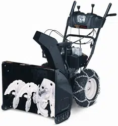
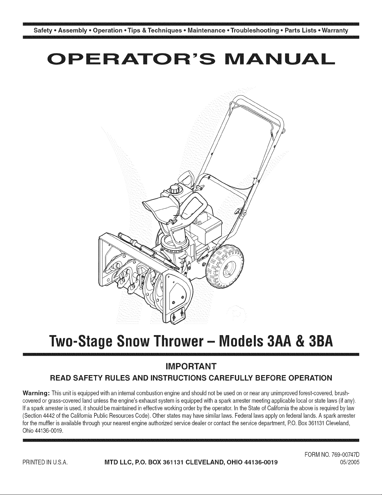
Tw0-Sta e n0wThr0wer- els
iMPORTANT
READ SAFETY RULES AND iNSTRUCTiONS CAREFULLY BEFORE OPERATION
Warning: Thisunit is equippedwithan internalcombustionengineandshouldnot beusedon or nearany unimprovedforest-covered,brush-
coveredor grass-coveredlandunlesstheengine'sexhaustsystemis equippedwitha sparkarrestermeetingapplicablelocalor statelaws(if any).
If a sparkarresteris used,it shouldbemaintainedineffectiveworkingorderby the operator.In theStateof Californiathe aboveis requiredbylaw
(Section4442of the CaliforniaPublicResourcesCode).Otherstatesmayhavesimilarlaws.Federallawsapplyonfederallands.A sparkarrester
for the muffleris availablethroughyour nearestengineauthorizedservicedealeror contactthe servicedepartment,RO. Box361131Cleveland,
Ohio44136-0019.
PRINTEDIN U.S.A.
MTD LLC, P.O. BOX 361131 CLEVELAND, OHIO 44136-0019
FORMNO.769-00747D
05/2005
This Operator's Manual is an important part of your new snow thrower, it will help you assemble,
prepare and maintain the unit for best performance. Please read and understand what it says.
Table of Contents
1. Safety Labels ............................................... 3
2. Safe Operation Practices ............................ 4
3. Setting UpYour Snow Thrower ................... 6
4. Know Your Snow Thrower ........................... 8
5. Operating Your Snow Thrower .................... g
6. Adjustments & Maintenance .................... 12
7. Off-Season Storage ................................... 14
8. Troubleshooting ......................................... 15
g. Parts List .................................................... 16
Warranty ..................................... Back Cover
Finding and Recording Model Number
BEFOREYOU START ASSEMBLING
YOUR NEW EQUIPMENT,
please locatethe model plate on the equipment and copy the
informationto the sample model plate provided to the right.
You can locate the model plate by standing at the operating
position and looking down at the rear of the snow thrower.
This information will be necessary to use the manufacturer's
web site and/or obtain assistance from the Customer Support
Department or an authorized service dealer.
Model Number
_www.rntdproducts.corn
Serial Number
MTD LLC
P.O. BOX 361131
CLEVELAND, OH 44136
330-220-4683
800-800-7310j
Customer Support
Please do NOTreturn the unit to the retailer from which it was
purchased, without first contacting Customer Support.
If you have difficulty assembling this product or have any questions regardingthe controls, operation, or maintenanceof this
unit,you can seek help from the experts. Choose from the options below:
1. Visit mtdproducts.com Click on the Service & Support menuoption.
2. Phone a Customer Support Representative at 1 (800) 800-7310.
3. The engine manufacturer is responsiblefor all engine-related issues with regardsto performance,power-rating,specifica-
tions, warranty and service. Please refer to the engine manufacturer'sOwner's/Operator's Manual, packed separatelywith
your unit, for more information.
MTD _rit_r_fi_a_
Award Winning _rod_f_ O,_r Cc,mp_y
Ser,_ice 8_Supper±
Product. Registration
Priwey P_y
2
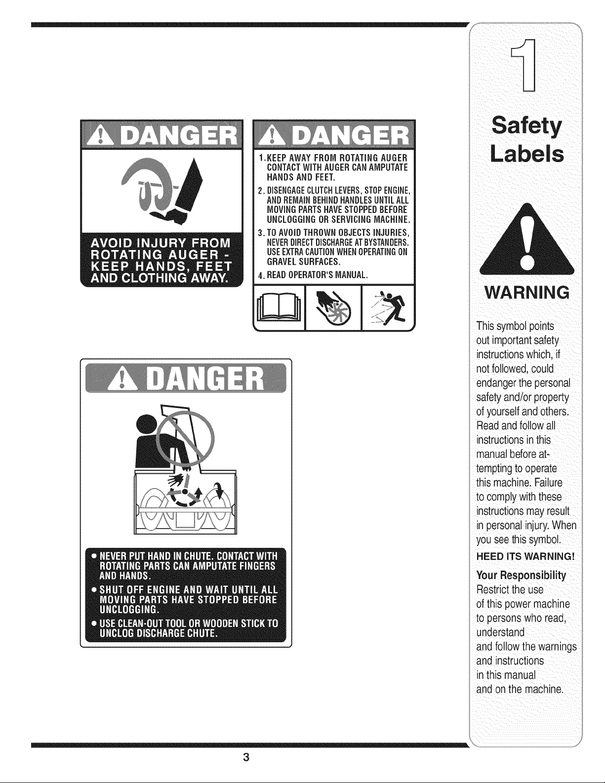
1.KEEPAWAYFROMROTATINGAUGER
CONTACTWiTHAUGERCANAMPUTATE
HANDS AND FEET.
2.DISENGAGECLUTCHLEVERS,STOPENGINE,
ANDREMAINBEHINDHANDLESUNTILALL
MOVINGPARTSHAVESTOPPEDBEFORE
UNCLOGGINGOR SERViCiNGMACHINE.
3. TO AVOIDTHROWN OBJECTSiNJURiES,
NEVERDIRECTDISCHARGEATBYSTANDERS.
USEEXTRACAUTIONWHENOPERATINGON
GRAVELSURFACES.
4.READOPERATOR'SMANUAL
3
Safety
WARNING
This symbol points
out importantsafety
instructionswhich, if
not followed,could
endangerthe personal
safety and/or property
of yourselfand others.
Readand follow all
instructionsinthis
manual beforeat-
temptingto operate
this machine. Failure
to comply with these
instructionsmay result
in personalinjury.When
you see this symbol.
HEED ITS WARNING!
Your Responsibility
Restrictthe use
of this power machine
to persons who read,
understand
and follow the warnings
and instructions
in this manual
and onthe machine.
WARNING
This symbol points
out importantsafety
instructionswhich, if
notfollowed,could
endangerthe personal
i safety and/or property
I ofyourselfand others.
Readand follow all
instructionsinthis
manual beforeat-
temptingto operate
i this machine. Failure
I to comply with these
instructionsmay result
i in personalinjury.When
you see this symbol.
i HEED ITS WARNING!
Your Responsibility
Restrictthe use
of this power machine
to personswho read,
_ understand
ano follow the warnings
and instructions
in this manual
and on the machine.
WARNING: Engine Exhaust,some of its constituents, and certain vehicle compo-
nents contain or emit chemicals knownto State of Californiato cause cancer and
birth defects or other reproductiveharm.
DANGER: This machine was built to be operated according to the rules for safe operation in this
manual. As with any type of power equipment, carelessness or error on the part of the operator can
result in serious injury.This machine is capable of amputating hands and feet and throwing objects.
Failureto observe the followingsafety instructions could result in serious injury or death.
Training
1. Read,understand,andfollowall instructionson the 1.
machineandin the manual(s)beforeattemptingto
assembleand operate.Keepthis manualina safe placefor
future andregularreferenceandfor orderingreplacement
parts. 2.
2. Be familiarwithall controlsandtheir properoperation.
Knowhowto stopthe machineanddisengagethem quickly.
3. Neverallow childrenunder14 yearsoldto operatethis
machine.Children14yearsold andovershouldread and
understandtheoperationinstructionsand safetyrulesin 3.
this manualand shouldbe trainedand supervisedbya
parent.
4. Neverallow adultsto operatethis machinewithoutproper
instruction.
5. Thrownobjectscan causeserious personalinjury.Plan 4.
yoursnow-throwingpatternto avoiddischargeof material
toward roads,bystandersandthe like.
6. Keepbystanders,helpers,pets andchildrenat least 75 feet 5.
from the machinewhileit is in operation.Stopmachineif
anyoneentersthe area. 6.
7. Exercisecautionto avoidslippingor falling,especially 7.
whenoperatingin reverse.
8,
9.
Preparation
Thoroughlyinspectthe area wherethe equipmentis to be
used. Removeall doormats,newspapers,sleds,boards,
wiresand otherforeignobjects,whichcould be tripped over
orthrown bythe auger/impeller.
Alwayswearsafetyglasses or eye shieldsduringoperation
andwhile performingan adjustmentor repairto protectyour
eyes.Thrownobjectswhich ricochetcan cause serious
injuryto the eyes.
Do notoperatewithoutwearingadequatewinterouter
garments.Do notwearjewelry, long scarvesor other
looseclothing,whichcould becomeentangledin moving
parts. Wearfootwearwhich willimprovefooting on slippery
surfaces.
Usea groundedthree-wireextensioncordand receptacle
for all units withelectric startengines.
Adjustcollectorhousingheight to cleargravel orcrushed
rocksurfaces.
Disengageallcontrol leversbeforestartingthe engine.
Neverattemptto makeany adjustmentswhileengineis
running,exceptwherespecificallyrecommendedinthe
operator'smanual.
Letengine andmachineadjustto outdoortemperature
beforestartingto clearsnow.
Toavoid personalinjuryor propertydamage use extreme
care inhandling gasoline.Gasolineis extremelyflammable
andthe vaporsare explosive.Serious personalinjurycan
occurwhengasolineis spilledon yourselforyour clothes,
whichcan ignite.Washyour skinand changeclothes
immediately.
a. Useonly an approvedgasolinecontainer.
b. Extinguishall cigarettes,cigars, pipesandothersources
of ignition.
c. Neverfuel machineindoors.
d. Neverremovegas cap or add fuel while the engineis hot
or running.
e. Allow engineto coolat leasttwo minutesbeforerefuel-
ing.
f. Neveroverfill fuel tank. Filltank to no morethan Y2inch
below bottomoffiller neckto providespacefor fuel
expansion.
g. Replacegasolinecap andtighten securely.
h. If gasolineis spilled,wipe it off theengine and equip-
ment. Movemachineto anotherarea. Wait 5 minutes
beforestartingthe engine.
i. Neverstorethe machineor fuel containerinside where
there is an openflame, sparkor pilot light (e.g.furnace,
waterheater,spaceheater,clothesdryeretc.).
j. Allow machineto cool at least 5 minutesbeforestoring.
4

Operation
1. Donot puthands orfeet near rotatingparts, inthe
auger/impellerhousingor chuteassembly.Contactwiththe
rotatingparts can amputatehands andfeet.
2. The auger/impellercontrolleveris a safetydevice.Never
bypassits operation.Doingso makesthe machineunsafe
and may causepersonalinjury.
3. The controlleversmustoperate easilyin bothdirections
and automaticallyreturnto the disengagedpositionwhen
released.
4. Neveroperatewith a missingor damagedchuteassembly.
Keepall safetydevicesin place andworking.
5. Neverrunan engineindoorsor in a poorlyventilatedarea.
Engineexhaustcontainscarbonmonoxide,an odorlessand
deadly gas.
6. Donot operatemachinewhile underthe influenceof alcohol
or drugs.
7. Mufflerandengine becomehot andcan causea burn.Do
nottouch.
8. Exerciseextremecaution whenoperatingonor crossing
gravel surfaces.Stayalert for hidden hazardsor traffic.
9. Exercisecaution whenchangingdirectionandwhile operat-
ingon slopes.
10.Plan yoursnow-throwingpatternto avoid dischargetowards
windows,walls, cars etc. Thus,avoidingpossibleproperty
damage or personalinjury causedby a ricochet.
11.Neverdirect dischargeat children,bystandersand petsor
allow anyonein frontof the machine.
12.Donot overloadmachinecapacity byattemptingto clear
snow at too fast of a rate.
13.Neveroperatethis machinewithoutgoodvisibility or light.
Alwaysbe sure of yourfooting and keepa firm holdon the
handles.Walk,neverrun.
14.Disengagepowerto the auger/impellerwhentransportingor
notin use.
15.Neveroperatemachineat hightransport speedson slippery
surfaces. Lookdownand behindand usecare when
backingup.
16.Ifthe machineshouldstartto vibrate abnormally,stopthe
engine,disconnectthe sparkplug wire and groundit against
the engine.Inspectthoroughlyfor damage.Repairany
damage beforestartingandoperating.
17.Disengageallcontrol leversandstop engine beforeyou
leavethe operatingposition (behindthe handles).Wait
untilthe auger/impellercomesto a completestop before
uncloggingthe chuteassembly,makingany adjustments,or
inspections.
18.Neverputyourhand in the dischargeor collectoropenings.
Alwaysuse the clean-outtoolprovidedto unclogthe dis-
charge opening.Donot unclogchuteassemblywhileengine
is running.Shut off engine and remainbehindhandlesuntil
all movingparts havestoppedbefore unclogging.
19.Useonly attachmentsandaccessoriesapprovedbythe
manufacturer(e.g.wheelweights,tire chains,cabs etc.).
20. If situationsoccurwhich are not coveredin this manual,
use careand goodjudgment.Contactyourdealeror call
(800) 800-7310for assistanceand the nameof your nearest
servicing dealer..
Maintenance & Storage
1. Nevertamper withsafetydevices.Checktheir proper
operationregularly.Referto the maintenanceandadjust-
mentsectionsof this manual.
2. Beforecleaning,repairing,or inspectingmachinedisen-
gageall control leversandstopthe engine.Wait untilthe
auger/impellercometo a completestop. Disconnectthe
sparkplugwire and groundagainstthe engineto prevent
unintendedstarting.
3. Checkbolts and screwsfor propertightness at frequent
intervalsto keepthe machinein safeworkingcondition.
Also,visually inspectmachinefor any damage.
4. Do not changethe enginegovernorsettingor over-speed
theengine.The governorcontrols the maximumsafe
operatingspeed of the engine.
5. Snowthrowershaveplatesand skidshoesare subjectto
wearanddamage. For yoursafetyprotection,frequently
check all componentsand replacewith originalequipment
manufacturer's(OEM) parts only."Useof partswhich do
notmeetthe original equipmentspecificationsmayleadto
improperperformanceandcompromisesafety!"
6. Checkcontrols periodicallyto verify theyengageand
disengageproperlyandadjust, if necessary.Referto the
adjustmentsection inthis operator'smanualfor instructions.
7. Maintainor replacesafetyandinstructionlabels,as neces-
sary.
8. Observeproperdisposallaws andregulationsfor gas,oil,
etc.to protectthe environment.
9. Priorto storing,run machinea few minutesto clearsnow
from machineand preventfreeze up of auger/impeller.
10.Neverstorethe machineorfuel containerinside where
thereis an openflame, sparkor pilot lightsuch as a water
heater,furnace, clothesdryeretc.
11.Alwaysreferto theoperator'smanualfor properinstructions
on off-seasonstorage.
Do not modify engine
Toavoid seriousinjuryor death,do not modifyengine in any
way.Tamperingwiththe governorsettingcan leadto a runaway
engineandcauseit to operateat unsafespeeds.Nevertamper
withfactorysettingof enginegovernor.
Notice regarding Emissions
Engineswhichare certifiedto complywithCaliforniaandfederal
EPAemissionregulationsfor SORE(SmallOff RoadEquipment)
arecertifiedto operateon regularunleadedgasoline,and may
includethe followingemissioncontrolsystems:EngineModifica-
tion (EM)andThreeWayCatalyst(TWO)ifso equipped.
Your Responsibility
Restrictthe useof this powermachineto personswho read,un-
derstandand followthe warningsand instructionsin this manual
andon the machine.
5
Operation
Practices
WARNING
This symbol points
out important safety
nstructions, which if
not followed, could
endangerthe personal
safety and/or property
of yourselfand others.
Readand follow all
instructions in this man-
ual before attempting to
operate this machine.
Failureto comply with
these instructionsmay
result in personal injury.
When you see this
symbol.
HEED IT'S WARNING!
Your Responsibility
Restrictthe use
of this power machine
to persons who read.
understand
and follow the warnings
_nd instructions
in this manua
and on the machine.
WARNING
Disconnectthe
spark plug wire
and ground it
against the engine
to prevent
unintendedstarting.
Do not use the
chute handle to lift
the snow thrower.
Referto the tire's
sidewallfor proper
PSiinflation.Equal
tirepressureshould
bemaintainedat all
times.Excessive
i pressurewhenseat=
ingbeadsmay cause
tire/rimassembly
to burstwithforce
sufficient to cause
seriousinjury.
NOTEI
All references toleft
or right side of the
snow thrower is
operating
position only.
IMPORTANT:Thisunit isshippedwith the enginefull of
oil. Afterassembly,seepage 9 for fuel and oil details.
Before Assembly
_ WARNING:Disconnectthe spark plug
wire and Ground it against the engine
to prevent unintended starting.
NOTE:Referenceto right,left,frontor rear ofthe unitis
fromtheoperatingpositionunlessotherwisestated.
1. Cutthe cabletie that securesthe upper handleto
the chuteassemblyfor shippingpurposes.
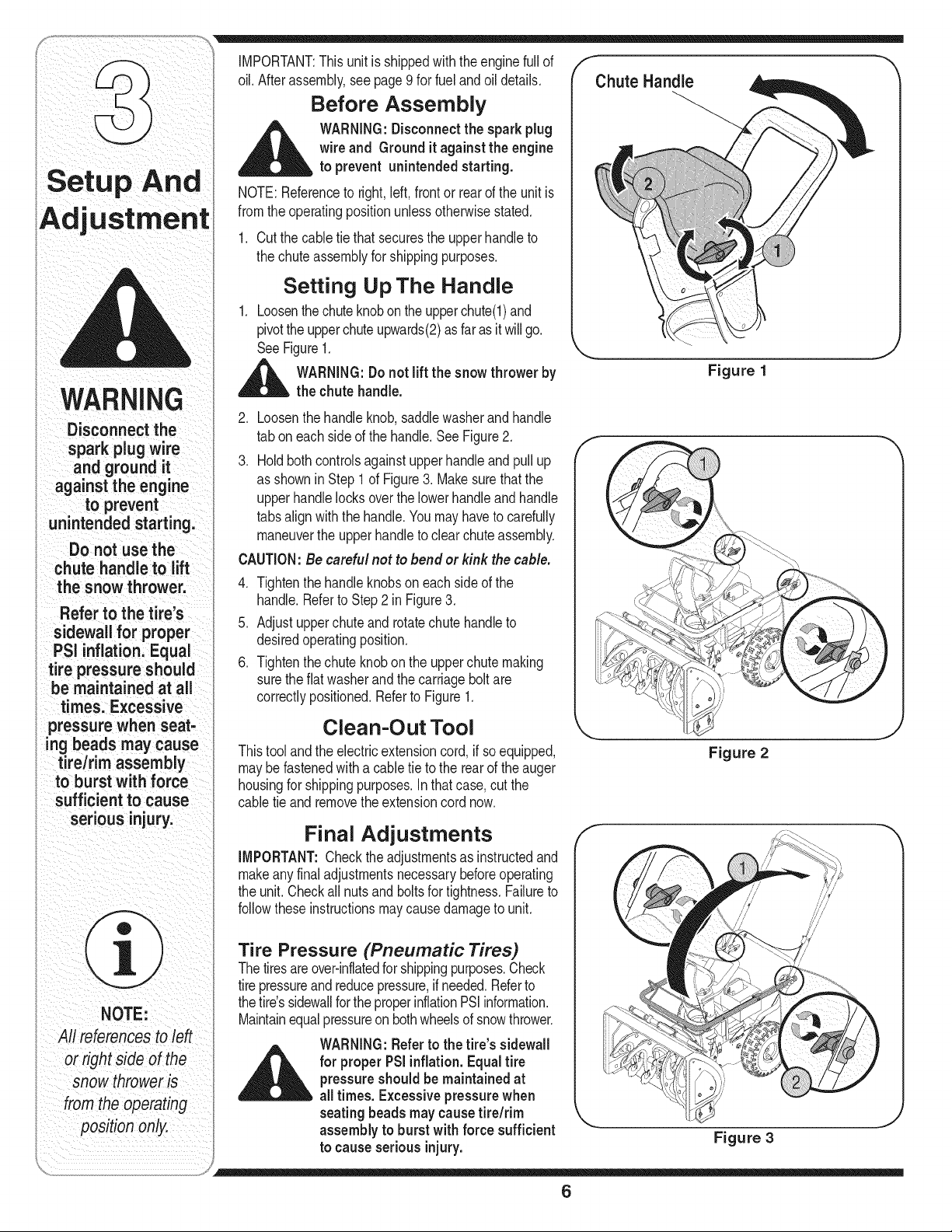
Setting Up The Handle
1. Loosenthe chuteknobon theupperchute(l) and
pivotthe upperchuteupwards(2)as faras it willgo.
SeeFigure1.
,_ WARNING:Do not lift the snow thrower by
the chute handle.
Chute Handle
Figure 1
J
2. Loosenthe handleknob, saddlewasherandhandle
tab oneachside of the handle.See Figure2.
3. Holdboth controlsagainstupperhandleand pull up
as shownin Step1 of Figure3. Makesurethat the
upperhandlelocksoverthe lowerhandle and handle
tabsalign with the handle.Youmay haveto carefully
maneuverthe upperhandleto clearchuteassembly.
CAUTION:Be careful not to bend or kink the cable.
4. Tightenthe handleknobsoneach sideof the
handle.Referto Step2 inFigure3.
5. Adjustupperchuteand rotatechute handleto
desiredoperatingposition.
6. Tightenthechuteknobon the upperchute making
surethe flatwasherandthe carriagebolt are
correctlypositioned.Referto Figure1.
f
Clean-Out Tool
Thistoolandthe electricextensioncord, if so equipped,
maybe fastenedwith a cabletie to the rear of the auger
housingfor shippingpurposes.In thatcase,cutthe
cabletie and removetheextensioncord now.
Figure 2
Final Adjustments
IMPORTANT:Checktheadjustmentsas instructedand
makeany finaladjustmentsnecessarybeforeoperating
the unit.Checkall nuts and bolts for tightness.Failureto
followtheseinstructionsmay causedamageto unit.
Tire Pressure (Pneumatic Tires)
Thetiresareover-inflatedforshippingpurposes.Check
tirepressureand reducepressure,if needed.Referto
thetire'ssidewallfortheproperinflationPSiinformation.
Maintainequalpressureonbothwheelsof snowthrower.
WARNING:Referto the tire's sidewall
A or properPSiinflation.Equal tire
pressureshould be maintained at
all times. Excessive pressurewhen
seating beads may cause tire/rim
assembly to burst with force sufficient
Figure 3
6
f
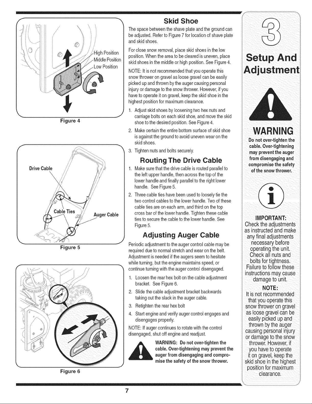
DriveCable
//
Figure 4
\
Figure 5
h Position
MiddlePosition
LowPosition
Figure 6
Skid Shoe
The spacebetweenthe shaveplateandthe groundcan
beadjusted.Referto Figure7 for locationof shaveplate
andskid shoes.
Forclosesnowremoval,place skidshoesin the low
position.Whenthe areato be clearedis uneven,place
skidshoes in the middleor high position.See Figure4.
NOTE:Itisnot recommendedthatyou operatethis
snowthrowerongravelas loosegravelcan be easily
pickedupand thrownbythe augercausingpersonal
injuryor damageto the snowthrower.However,if you
haveto operateit on gravel,keepthe skid shoeinthe
highestpositionfor maximumclearance.
1. Adjustskidshoes by looseningtwo hexnuts and
carriagebolts on each skid shoe,and movethe skid
shoeto the desiredposition.See Figure4.
2. Makecertainthe entirebottomsurfaceof skidshoe
is againstthe groundto avoidunevenwearon the
skidshoes.
3. Tightennutsand bolts securely.
.
.
Routing The Drive Cable
Makesurethatthe drivecane is routedparallelto
the leftupper handle,thenacrossthe topof the
lowerhandleandfinally parallelto the rightlower
handle. SeeFigure5.
Threecabletieshavebeenusedto looselytie the
twocontrolcablesto the lowerhandle.Twoof these
cabletiesareon eacharm,and thirdon thetop
crossbarof the lowerhandle.Tightenthesecable
tiesto securethe cableto the lowerhandle.See
Figure5.
Adjusting Auger Cable
Periodicadjustmentto theauger controlcablemay be
requireddueto normalstretchand wearon the belt.
Adjustmentis neededif the augersseemto hesitate
whileturning,but theenginemaintainsspeed,or
continueturningwiththe augercontroldisengaged.
1. Loosenthe rearhex bolton the cableadjustment
bracket. See Figure6.
2. Slidethe cableadjustmentbracketbackwards
takingoutthe slackinthe augercable.
3. Retightenthe rear hexbolt
4. Startengineand verifyaugercontrolengagesand
disengagesproperly.
NOTE:Ifaugercontinuesto rotatewith the control
disengaged,shutoff engineandreadjust.
__i= ARNING: Donotover-tighten the
cable.Over-tightening mayprevent the
auger from disengagingand compro-
misethe safetyof the snowthrower.
Setup And
WARNING
Do not Over,tightenthe
cable,Over4ightening
mayprevent the auger
fro mdisengagingand
compromisethe safety
of the snowthrower.
IMPORTANT:
Check the adjustments
as instructedand make
any final adjustments
necessarybefore
operatingthe unit,
Check all nuts
bolts for tightness.
Failureto follow these
instrUctions maycause
damage to unit
NOTE:
it is not recommended
that you operate this
snowthrower on gravel
loose grave!can be
easily pickedup and
thrown bythe auger
causing personalinjury
or damageto the snow
thrower: Howeverif
youhave to Operate
it on gravel;keep the
skid shoe in the highest
positionfor maximum
Clearance:
7
Know
WARNING
Be familiar with
all the controls on
the snow thrower
and their proper
i operation.Knowhow
tostop the machine
anddisengagethem
quickly.
Never make
adjustments to the
chuteassembly
unlessbothauger
i and drive controls are
i disengaged andthe
operator is standing
beside the unit.
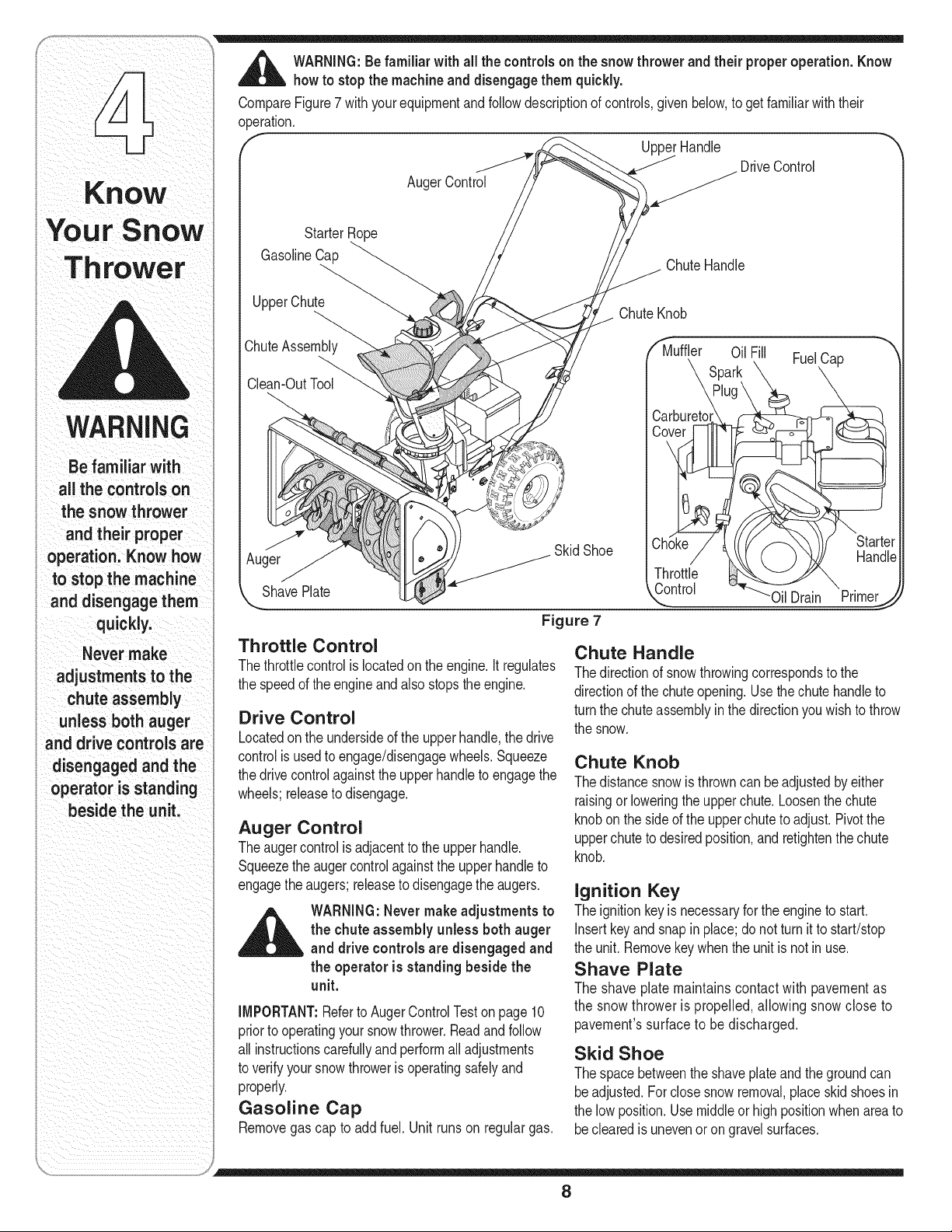
,_ WARNING:Be familiar with all the controls onthe snowthrower and their properoperation.Know
howto stopthe machineand disengagethemquickly.
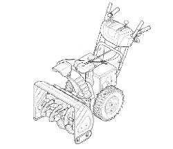
CompareFigure7 withyourequipmentandfollowdescriptionof controls,givenbelow,to get familiarwiththeir
operation.
UpperHandle
DriveControl
AugerControl
StarterRope
GasolineCap
ChuteHandle
UpperChute
ChuteKnob
_huteAssembly
Clean-OutTool
Auger
ShavePlate
Throttle Control
Muffler OilFill FuelCap
Spark
Carburetom
Skid Shoe
Figure 7
Throttle
Control
Chute Handle
Starter
Handle
Thethrottlecontrolis locatedon the engine.Itregulates
the speedof theengineand alsostopsthe engine.
Drive Control
Locatedon the undersideof the upperhandle,the drive
controlis usedto engage/disengagewheels.Squeeze
the drivecontrolagainstthe upperhandleto engagethe
wheels;releaseto disengage.
Auger Control
Theaugercontrolis adjacentto the upperhandle.
Squeezethe auger controlagainstthe upperhandleto
engagetheaugers;releaseto disengagetheaugers.
_ ARNING:Never makeadjustments to
the chuteassembly unlessboth auger
and drivecontrolsare disengaged and
the operatoris standingbeside the
unit.
IMPORTANT:Referto AugerControlTestonpage 10
priorto operatingyour snowthrower.Readand follow
all instructionscarefullyand performall adjustments
to verifyyoursnowthroweris operatingsafelyand
properly.
Gasoline Cap
Removegas cap to add fuel. Unit runson regular gas.
Oil Drain Primer
Thedirectionof snowthrowingcorrespondsto the
directionof the chuteopening.Use the chutehandleto
turnthe chuteassemblyinthedirectionyouwishto throw
the snow.
Chute Knob
Thedistancesnowis throwncan beadjustedby either
raisingorloweringthe upperchute.Loosenthe chute
knobon theside of the upperchuteto adjust.Pivotthe
upperchuteto desiredposition,and retightenthe chute
knob.
Ignition Key
Theignitionkeyisnecessaryfor the engineto start.
Insertkeyandsnapin place;do not turnit to start/stop
the unit.Removekey whenthe unit isnot inuse.
Shave Plate
The shave plate maintainscontact with pavementas
the snowthrower is propelled, allowing snow close to
pavement'ssurface to be discharged.
Skid Shoe
Thespacebetweenthe shaveplateandthe groundcan
beadjusted.For closesnow removal,placeskid shoesin
the lowposition.Usemiddleor high positionwhenareato
beclearedis unevenor on gravelsurfaces.
8
Before Starting Engine
Engine Oil
The engineisshippedwith oil in it. Checkthe oil level
beforefirst use.
1. Stop engineandwait severalminutesbeforechecking
oil level.Removeoil fill capanddipstick.
2. Wipedipstickclean,insertit intooil fill holeand
tightensecurely.
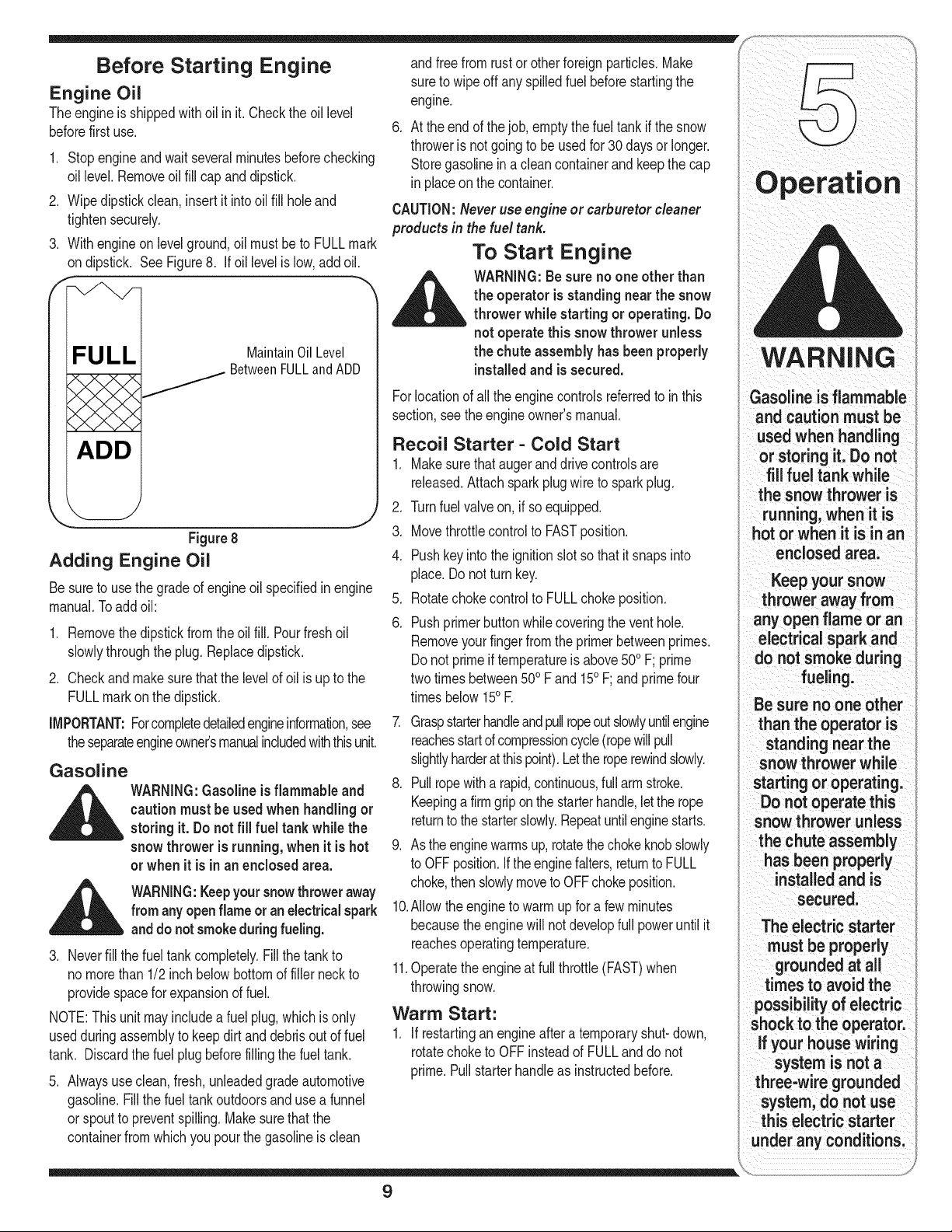
3. Withengineon levelground,oil mustbe to FULLmark
on dipstick. SeeFigure8. If oil levelis low, add oil.
FULL
ADD
Maintain Oil Level
BetweenFULLand ADD
Figure8
Adding Engine Oil
Besureto use thegradeof engineoil specifiedin engine
manual.Toaddoil:
1. Removethe dipstickfrom theoil fill. Pourfresh oil
slowlythroughthe plug. Replacedipstick.
2. Checkandmake surethatthe levelof oil is up to the
FULLmarkon the dipstick.
IMPORTANT:Forcompletedetailedengineinformation,see
theseparateengineowneCsmanualincludedwiththisunit.
Gasoline
_ ARNING:Gasolineis flammable and
caution must be used when handling or
storing it. Do not fill fuel tank while the
snowthrower is running, when it is hot
or when it is in an enclosedarea.
_ WARNING:Keepyoursnowthrower away
from anyopenflameor an electricalspark
anddo not smokeduring fueling.
3. Neverfill the fuel tankcompletely.Fillthe tankto
no morethan 1/2inch belowbottomof filler neck to
providespacefor expansionof fuel.
NOTE:This unitmay includea fuel plug,which is only
usedduringassemblyto keepdirt anddebrisout of fuel
tank. Discardthe fuel plug beforefillingthe fuel tank.
5. Alwaysuseclean,fresh,unleadedgradeautomotive
gasoline.Fillthe fuel tankoutdoorsand usea funnel
or spoutto preventspilling.Makesurethatthe
containerfromwhichyou pourthe gasolineis clean
andfreefromrust or otherforeignparticles.Make
sureto wipeoff any spilledfuel beforestartingthe
engine.
6. At the endof thejob, emptythe fueltank if the snow
throweris notgoingto be usedfor30 daysor longer.
Storegasolinein a cleancontainerand keepthe cap
in placeon the container.
CAUTION:Never use engine or carburetor cleaner
productsin the fuel tank.
To Start Engine
,1_ WARNING:Besure no one other than
the operator is standing near the snow
thrower while starting or operating. Do
not operate this snow thrower unless
the chute assembly has been properly
installedand issecured.
Forlocationof all the enginecontrolsreferredto in this
section,seethe engineowner'smanual.
Recoil Starter - Cold Start
1. Makesurethatauger and drivecontrolsare
released.Attachsparkplugwire to sparkplug.
2. Turnfuel valveon, if soequipped.
3. Movethrottlecontrolto FASTposition.
4. Pushkeyintothe ignitionslotso that itsnaps into
place.Do not turnkey.
5. Rotatechokecontrol to FULLchoke position.
6. Pushprimerbuttonwhilecoveringthe venthole.
Removeyour fingerfromthe primerbetweenprimes.
Do not primeif temperatureis above500F; prime
twotimesbetween500Fand 150F;andprimefour
timesbelow150E
7. Graspstarterhandleandpullropeoutslowlyuntilengine
reachesstartd compressioncycle(ropewillpull
slightlyharderat thispoint).Letthe roperewindslowly.
8. Pullropewitha rapid,continuous,full armstroke.
Keepinga firmgriponthe starterhandle,letthe rope
returnto thestarterslowly.Repeatuntilenginestarts.
9. Asthe enginewarmsup, rotatethechokeknobslowly
to OFFposition.If theenginefalters,returnto FULL
choke,then slowlymoveto OFFchokeposition.
10.Allowthe engineto warmup fora few minutes
becausethe enginewill not developfull poweruntil it
reachesoperatingtemperature.
11.Operatethe engineat full throttle(FAST)when
throwingsnow.
Warm Start:
1. If restartingan engineafter a temporaryshut-down,
rotatechoketo OFFinsteadof FULLanddo not
prime.Pullstarterhandleas instructedbefore.
WARNING
Gasoline is flammable
and caution must be
used when handling
or storing it. Do not
fill fuel tank while
the snow thrower is
running, when it is
hot or when it is in an
enclosed area.
Keep your snow
thrower away from
any open flame or an
electrical spark and
do not smoke during
fueling.
Be sure no one other
than the operator is
standing near the
snow thrower while
starting or operating.
Do not operate this
snow thrower unless
the chute assembly
has been properly
installedand is
secured.
The electric starter
must be properly
groundedat all
times to avoid the
possibilityof electric
shock to the operator.
if your house wiring
system is not a
three-wire grounded
system, do not use
this electric starter
under any conditions.
9
WARNING
Severe damage
to electric starter
is possible if you
continueto crank
for morethan
5 seconds without
a cooFdown.
The temperature
of muffler and the
surrounding areas
may exceed150o E
i Avoid these areas
Electric Starter(if equipped)
Somemodelsof the snowthrowermaybe equipped
withan optional120volt A.C.electricstarter.This
electricstarter,witha three-wirepowercordand plug, is
designedto operateon 120voltAC householdcurrent.
Followthe stepsbelowto usethe electricstarter.
Cold Start:
1. Determinewhetheryourhousewiringis athree-wire
groundedsystem.Aska licensedelectricianifyou
arenotcertain.
__IL ARNING:The electricstartermust
be properly groundedat all times to
avoid the possibilityof electricshock
to the operator. If your housewiring
systemis not a three-wire grounded
system,do not use this electric starter
under any conditions.
2. If yourhousewiringsystemis groundedanda three-
holereceptacleis notavailableat the pointthe snow
throwerstarterwill normallybe used,one shouldbe
installedbya licensedelectrician.
NOTE:Whenconnectingthe powercord,alwaysconnect
cordto starteron enginefirst,then plugtheotherend
intoathree-holegrounded120Voltreceptacle.When
disconnectingthe powercord,alwaysunplugtheend
fromthethree-hole,groundedreceptaclefirst.
3. Attachsparkplugwireto sparkplug.
4. Makesurethatthe augercontrol and the drive
controlaredisengaged.
5. Removethekeysfrom the plasticbag.Pushkey into
the ignitionslot. Do notturn the key.Keepsecond
keyin a safe place.
6. Movethe chokeknobto FULLchokeposition.
7. Movethrottlecontrolto the FASTposition.
8. Turnfuel valveon, if soequipped.
9. Connectpowercord to the switchbox onengine.
10.Plugthe otherend of the powercordinto a three-
hole,grounded120voltAC receptacle.
11.Pushprimerbuttonthreetimes.
12.Pushdownon the starterbuttonuntiltheengine
starts.Donotcrankformorethan5 secondsat atime.
_ ARNING:Severe damageto electdc
starteris possibleif you continueto
crankfor more than 5 secondswithout
a cool-down.
13.Whentheenginestarts,releasethe starterbutton
andslowlyrotatethe choketo OFFposition.If the
enginefalters,rotatethe choketo FULLandthen
graduallyto OFR
NOTE:Whenengagingthe electricstarter,a slight
hesitationof a few secondsmayoccur beforethe
enginestartsto turn. This isnormaland is not harmful
to the engine.
14.Disconnectthe powercordfromthe receptaclefirst
andthenfrom the switchboxon the engine.
15.Allowthe engineto warmupfor a few minutes
becausethe enginewill not developfull poweruntilit
reachesoperatingtemperature.
NOTE:Ifthe startermotorrunsbutthe enginedoes not
turnover,the startergearmayhavefrozen.Placethe
snowthrowerin awarmerpart of the garageor storage
shedtill the gearisfreeof theaccumulatedice.
Warm Start:
1. if restartinga warmengine,rotatechoke to OFF
insteadof FULLandpress the starterbutton.Do not
pushthe primerbutton.
Before Stopping
1. Runenginefor a fewminutesto help dry off any
moistureon engine.
2. Toavoidpossiblefreeze-upof the starter,followthese
steps:
Recoil Starter
a. Withtheenginerunning,pull the starterropewith
a rapid,continuousfull arm strokethreeor fourtimes.
Electric Starter (if equipped)
a. Connectpowercordto switchbox, thento 120
VoltAC receptacle.
b. Whilethe engineisrunning,pushthe starter
buttonandspin the starterfor severalseconds.
c. Disconnectpowercordfrom the receptaclefirst,
thenfromthe snowthrower.
NOTE:Theunusualsoundfrompullingthe starterropeor
fromspinningthestarterwillnotharmtheengine.
3. Whilestandingintheoperator'sposition(behindthesnow
thrower),engagetheaugercontrolfora fewsecondsto
clearanyremainingsnowandicefromthechuteassembly.
To Stop The Snow Thrower
1. Tostopthe wheels,releasethe drivecontrol.
2. Tostopthrowingsnow,releasethe augercontrol.
3. Tostopengine,pushthrottlecontrol leverto OFFor
pullout the key(eithermethodworks). Donot turnkey.
__IL WARNING:Thetemperatureof muffler
and the surroundingareas mayexceed
150° F.Avoid these areas
Auger Control Test
IMPORTANT:Performthe followingtest beforeoperating
the snowthrowerforthe first timeand at the startof each
winterseason.
Checktheadjustmentof the augercontrolas follows:
1. Whentheaugercontrolis releasedand inthe
disengaged"up"position,the cableshouldhavevery
littleslack, but shouldNOT be tight.
10
_ ARNING:Donotover-tighten the
cable.Over-tighteningmayprevent the
augerfrom disengaging and compro-
misethe safetyof the snowthrower.
2. Ina well-ventilatedarea,startthe snowthrower
engineas instructedearlierin this sectionunderthe
headingStartingEngine.Makesurethe throttleisset
inthe FASTposition.
3. Whilestandinginthe operator'sposition(behindthe
snowthrower)engagethe auger.
4. Allowthe augerto remainengagedforapproximately
ten (10)secondsbeforereleasingthe augercontrol.
Repeatthis severaltimes.
5. Withthe enginerunningin the FASTpositionand the
augercontrolinthe disengaged"up" position,walkto
the frontof the machine.
6. Confirmthat the auger hascompletelystopped
rotatingand showsNO signsof motion.
iMPORTANT:Ifthe augershowsANYsignsof rotating,
immediatelyreturnto the operator'spositionand shut
off the engine.Wait forall movingparts to stop before
readjustingthe augercontrolcable as showninthe
"SetupAndAdjustment"sectionon page7.
Clearing The Snow
CAUTION:Checkthe area to be clearedforforeign
objects.Remove,if any.
1. Startthe enginefollowingstartinginstructions.
2. Allowthe engineto warmup for a few minutesas
the enginewill not developfull poweruntil itreaches
operatingtemperature.
3. Rotatethe chuteassemblyto the desireddirection,
awayfrombystandersand/or buildings.
4. Makingcertainnobystandersorobstaclesarein
frontof the unit, squeezethe augercontrolcompletely
againstthe upperhandleto fully engagethe augers.
5. Whilethe augercontrolisengaged,squeezethe drive
controlcompletelyagainstthe upperhandleto engage
the wheels.Donot "feather"the drivecontrol.
6. As the snowthrowerstartsto move,maintaina firm
holdon the handle,and guide thesnow throweralong
the pathto becleared.
7. Releasethe augeranddrivecontrolsto stopthe snow
throwingactionandforwardmotion.
NOTE:Yourunit isequippedwith a clutchin thetransmis-
sion.If the wheelsstop turningwhiletrying to discharge
largevolumesof snow,immediatelydisengagethe drive
controlandallow the rotatingaugersto dischargesnow
fromthe housing.Reducethe clearingwidth and continue
operation.
Operating Tips
1. Formost efficientsnowremoval,removesnow
immediatelyafterit falls.
2. Dischargesnowdownwindwheneverpossible.
Slightlyoverlapeachpreviousswath.
3. Setthe skid shoes1/4"belowthe shaveplatefor
normalusage.The skidshoesmaybeadjusted
upwardfor hard-packedsnow.
NOTE:Itis not recommendedthat you operatethis
snowthrowerongravelas loosegravelcan be easily
pickedupand thrownbythe augercausingpersonal
injuryand/ordamageto the snowthrower.
4. If for somereason,youhaveto operatethe snow
throweron gravel,keepthe skidshoeinthe highest
positionfor maximumclearancebetweentheground
andthe shaveplate.
5. Cleanthe snowthrowerthoroughlyaftereach use.
Cleaning The Chute Assembly
Theclean-outtool is convenientlyfastenedto the rear of
the augerhousingwith a mountingclip.
Whensnowandice collectin the chuteassemblyduring
operation,usethis toolto safelycleanthe chuteand
chuteopening.Followthe stepsbelowto operateit.
__IL ARNING:Stop engineby moving
throttle leverto stoppositionand wait
for all moving partsto stop before
using the clean-out tool.
1. Releasebothaugeranddrivecontrols.
2. Stopthe engineby movingthrottleleverto stop
position.
3. Removethe clean-outtool fromthe clip which
securesit to the rearof the auger housing.
4. Usethe shovel-shapedend of the clean-outtool to
dislodgeand scoop anysnow and icewhich has
formedinand nearthe chute assembly.
_ ARNING:Never use yourhands to
cleansnow and ice from the chute
assembly or auger housing.
5. Re-fastenthe clean-outtool to the mountingclip
onthe rear of the augerhousing.Youcan start
operatingyour snowthrowernow.
8. On eachsucceedingpass, readjustthe chute
assemblyto thedesiredpositionandslightlyoverlap
the previouslyclearedpath.
11
Operation
WARNING
Do not over-tighten
the cable. This may
prevent the auger
from disengaging
and compromise
the safety of the
snow thrower.
Stop engine by
moving throttle lever
to stop position and
wait for all moving
parts to stop
before using the
clean-out tool.
Never use your
hands to clean
snow and ice
from the chute
assembly or
auger housing.
CAUTION:
When preparing to
clear snow, be sure
to check the area to
be cleared for foreign
objects. Remove
objects, if any.
WARNING
Before lubricating,
repairing;or;
inspecting,disengage
a,controlsandstop
enginei Wait until all
moving partshave
come to a complete
stop, Disconnectthe
groundit againstthe
to prevent
unintended starting:
If auger continuesto
rotate withthe Control
disengagedl shut off
engineand rezadjust.
l
.
General Recommendations ShearPin "_
1. Alwaysobservesafetyruleswhen performingany Cotter Pin
maintenance.
2. Thewarrantyon this snowthrowerdoesnot cover Skid Shoe
itemsthathavebeensubjectedto operatorabuseor
negligence.Toreceivefull valuefrom the war-
ranty,operatormustmaintainthe snowthroweras
instructedin thismanual.
Periodicallycheckallfastenersand hardwareto
makesurethesearetight.
WARNING: Before servicing, repairing, ShavePlate
_ lubricatingor inspecting,disengage all He×Nut Carriage
controlsand stop engine.Wait until all
Bolt HexNut
J
moving parts have come to a complete j/
stop. Disconnect spark plug wire and Figure 9
ground it against the engineto prevent
unintendedstarting. Alwayswear safety
glasses during operation or while per-
formingany adjustmentsor repairs.
Replacing the Shave Plate
and Skid Shoes
Theshaveplateand skidshoesonthe bottomof the
snowthroweraresubjectto wear.Theseshouldbe
checkedperiodicallyand replacedwhennecessary
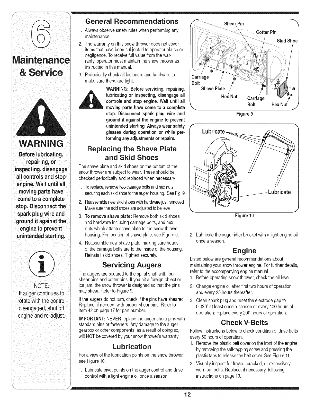
Toreplace,removetwo carriageboltsandhexnuts
securingeachskidshoetotheaugerhousing.SeeFig.9
2. Reassemblenewskidshoeswithhardwarejustremoved.
Makesuretheskidshoesareadjustedtobe level.
3. To removeshave plate: Removeboth skid shoes
andhardwareincludingcarriagebolts,and hex
nutswhichattachshaveplateto the snowthrower
housing.Forlocationof shaveplate,see Figure9.
4. Reassemblenew shaveplate,makingsureheads
of the carriagebolts are to the insideof the housing.
Reinstallskid shoes.Tighten securely.
Servicing Augers
Theaugersaresecuredto the spiralshaftwithfour
shearpinsandcotterpins.If you hita foreignobjector
icejam, the snowthroweris designedso that the pins
mayshear.Referto Figure9.
If the augersdo notturn, checkif thepins havesheared.
Replace,if needed,with propershearpins.Referto
item42 on page 17for part number.
IMPORTANT:NEVERreplacetheauger shearpinswith
standardpins orfasteners.Anydamageto theauger
gearboxor other components,as a resultof doingso,
will NOTbe coveredby yoursnowthrower'swarranty.
Lubrication
Fora viewof the lubricationpointson the snowthrower,
see Figure10.
1. Lubricatepivotpointson theauger controland drive
controlwitha lightengineoil oncea season.
Figure 10
J
2. Lubricatethe augeridlerbracketwith a lightengineoil
oncea season.
Engine
Listedbelowaregeneralrecommendationsabout
maintainingyour snowthrowerengine.Forfurther details,
referto the accompanyingenginemanual.
1. Beforeoperatingsnow thrower,checkthe oil level.
2. Changeengineoil afterfirst two hoursof operation
andevery25 hoursthereafter.
3. Cleansparkplugand resettheelectrodegap to
0.030"at leastonce a seasonorevery100hoursof
operation;replaceevery200 hoursof operation.
Check V-Belts
Followinstructionsbelowto checkconditionof drivebelts
every50 hoursof operation.
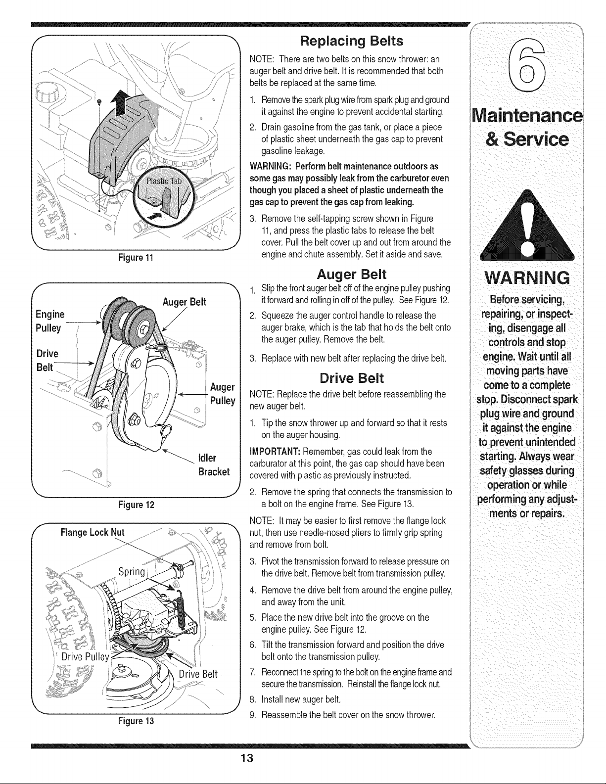
1. Removetheplasticbeltcoveron the frontof theengine
by removingthe self-tappingscrewand pressingthe
plastictabsto releasethebeltcover.SeeFigure11
2. Visuallyinspectfor frayed,cracked,or excessively
wornout belts.Replace,if necessary,following
instructionson page 13.
12
,m
f
Drive
Belt
\
Figure 11
Belt
Auger
i Pulley
Figure12
FlangeLockNut
Idler
Bracket
Drive Pulley
Drive Belt
Figure13
Replacing Belts
NOTE: Thereare two beltson this snowthrower:an
augerbelt anddrivebelt. It is recommendedthat both
beltsbe replacedat the sametime.
1. Removethesparkplugwirefromsparkplugandground
it againstthe engineto preventaccidentalstarting.
2. Draingasolinefrom the gastank,or placea piece
of plasticsheetunderneaththe gas capto prevent
gasolineleakage.
WARNING:Performbelt maintenanceoutdoors as
somegasmay possiblyleakfrom the carburetoreven
though youplaceda sheetof plasticunderneaththe
gas capto preventthe gascapfrom leaking.
3. Removethe self-tappingscrewshown in Figure
11,and pressthe plastictabs to releasethe belt
cover.Pull the beltcover up and out fromaround the
engineandchute assembly.Set it asideand save.
Auger Belt
1. Slipthefrontaugerbeltoff of theenginepulleypushing
itforwardandrollinginoff ofthe pulley.SeeFigure12.
2. Squeezetheauger controlhandleto releasethe
augerbrake,whichisthe tab that holdsthe beltonto
the augerpulley.Removethe belt.
3. Replacewith newbeltafter replacingthe drivebelt.
Drive Belt
NOTE:Replacethe drivebelt beforereassemblingthe
newaugerbelt.
1. Tipthe snowthrowerupand forwardso that it rests
onthe augerhousing.
IMPORTANT:Remember,gas could leakfromthe
carburatorat thispoint,thegas cap shouldhavebeen
coveredwithplasticas previouslyinstructed.
2. Removethe springthat connectsthe transmissionto
a bolton the engineframe.SeeFigure13.
NOTE: Itmay be easierto first removethe flangelock
nut,then useneedle-nosedpliersto firmlygripspring
andremovefrombolt.
Pivotthetransmissionforwardto releasepressureon
thedrivebelt.Removebeltfromtransmissionpulley.
.
4. Removethe drive beltfrom aroundthe enginepulley,
andawayfrom the unit.
5. Placethe newdrivebelt intothe grooveon the
enginepulley.SeeFigure12.
6. Tilt the transmissionforwardand positionthe drive
beltonto the transmissionpulley.
7. Reconnectthespringtothebolton theengineframeand
securethetransmission.Reinstalltheflangelocknut.
8. Installnewaugerbelt.
9. Reassemblethe belt coveronthe snowthrower.
WARNING
Before servicing,
repairing, or inspect-
ing, disengage all
controlsand stop
engine. Wait until all
moving partshave
cometo a complete
stop. Disconnectspark
plugwire and ground
it against the engine
to preventunintended
starting.Always wear
safetyglasses during
operation or while
performingany adjust-
mentsor repairs.
13
If the snowthrowerwill notbe usedfor30 daysor
WARNING
Never store snow
thrower with fuel
in tank indoors or
in poorly ventilated
areas, where fuel
fumes may reach an
open flame, spark
or pilot light as on a
furnace, water heater,
clothes dryer or
gas appliance.
Drainfuel intoan
i approved container
outdoors, away from
any open flame. Be
certain engine is
cool. Do not smoke.
Fuel left in engine
during warm weather
i deteriorates and
will cause serious
starting problems.
Do not drain
carburetor if using
fuel stabilizer.
Never use engine or
carburetor cleaning
products in the fuel
tank or permanent
damage may occur.
longer,or if it is theend of the snowseasonwhenthe
lastpossibilityof snowis gone,the equipmentneedsto
bestored properly.Followstorageinstructionsbelowto
ensuretop performancefrom the snowthrowerfor many
moreyears.
Preparing Engine
NOTE:Referto theenginemanualfor moredetailed
informationon preparingthesnowthrowerenginefor
storage.
_ ARNING:Neverstoresnowthrower
with fuel intank indoorsor in poorly
ventilated areas,wherefuel fumes
may reach an open flame, spark or
pilotlight as on a furnace, water
heater,clothes dryer or gas appliance.
NOTE:Itis importantto preventgumdepositsfrom
forminginessentialfuel systemparts of the enginesuch
as the carburetor,fuel filter,fuelhoseor tank during
storage.
CAUTION:Alcohol blended fuels (called gasohol
or using ethanol or methanol) canattract moisture
which leads to separation and formation of acids
during storage. Acidic gas can damage the fuel
system of an engine while in storage.
Toavoidengineproblems,thefuel systemshouldbe
emptiedbeforestoragefor 30 days or longer.Follow
theseinstructionsto prepareyour snowthrowerfor
storage:
_ ARNING:Drainfuel intoan approved
container outdoors, away from any
openflame. Becertain engineis cool.
Do not smoke. Fuel left in engine
during warm weather deteriorates and
will cause serious starting problems.
1. Removeall gasolinefrom the carburetorand thefuel
tankto preventgum depositsfrom formingon these
partsand harmingthe engine.
2. Runthe engineuntilthe fuel tankis emptyand it
stopsdueto lackof fuel.
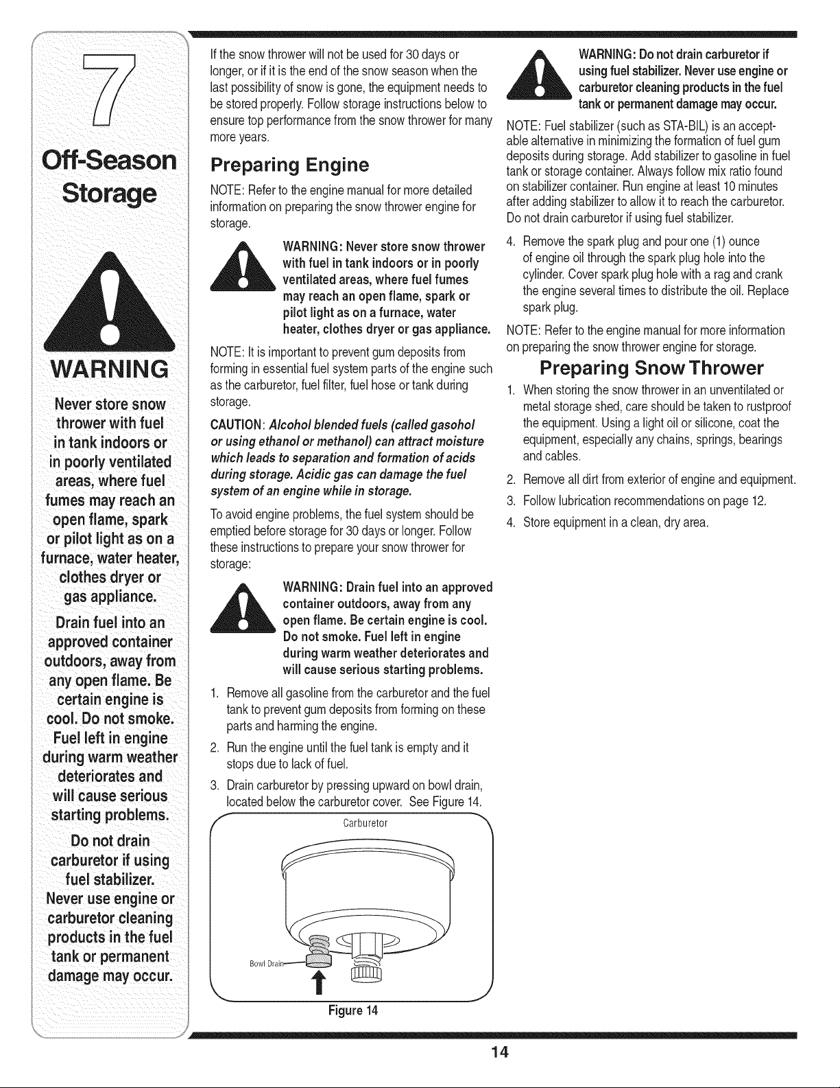
3. Draincarburetorby pressingupwardon bowldrain,
locatedbelowthe carburetorcover. See Figure14.
f Carburetor _'
Bowl Dral
Figure 14
__ ARNING:Donot drain carburetorif
using fuel stabilizer.Neveruse engineor
carburetorcleaningproducts in the fuel
tankor permanentdamagemayoccur.
NOTE:Fuelstabilizer(such as STA-BIL)is an accept-
ablealternativein minimizingthe formationof fuelgum
depositsduring storage.Add stabilizerto gasolineinfuel
tankor storagecontainer.Alwaysfollow mix ratiofound
onstabilizercontainer.Runengineat least 10 minutes
afteraddingstabilizerto allowit to reachthe carburetor.
Do notdraincarburetorif usingfuel stabilizer.
4. Removethespark plug and pour one (1) ounce
of engineoil throughthe sparkplug hole into the
cylinder.Coversparkplug hole with a rag and crank
the engineseveraltimesto distributethe oil. Replace
sparkplug.
NOTE:Referto theenginemanualfor moreinformation
onpreparingthe snowthrowerenginefor storage.
Preparing Snow Thrower
1. Whenstoringthe snowthrowerinan unventilatedor
metalstorageshed,careshouldbe takento rustproof
the equipment.Usinga light oil or silicone,coat the
equipment,especiallyanychains,springs,bearings
andcables.
2. Removeall dirt from exteriorof engineand equipment.
3. Followlubricationrecommendationson page 12.
4. Storeequipmentina clean,dry area.
14
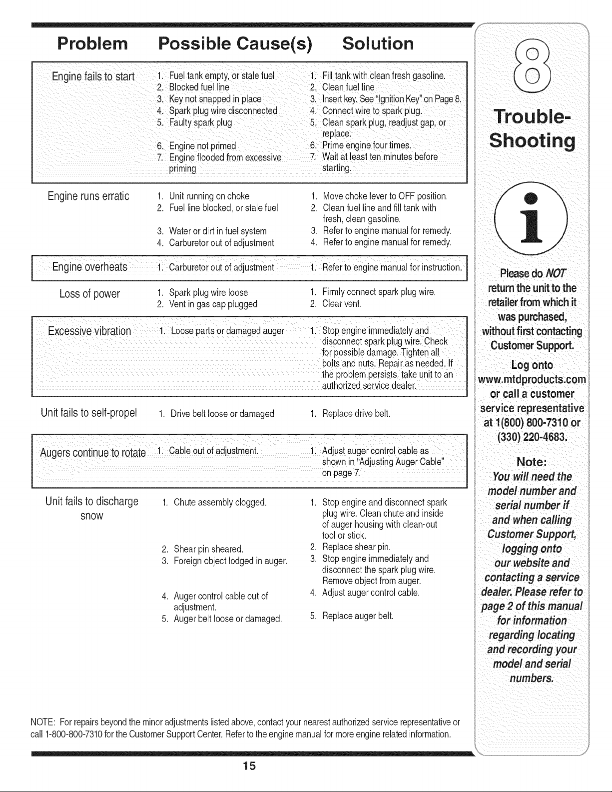
Problem Possible Cause(s) Solution
ginefailstostart ; e!tank emptylot Staefuel 1 Fill tankwith Cleanfresh gaSOl!ne
21 Blockedfuel line 2, Cleanfuel line
31 Keynot snappedin place 3, Insertkey,See!!gnitionKey on Page8
4, spark plugWredisconnected 4. connect wireto sparkpiugl
& Fau!tyspark plug c!ean sparkplug, readjustgap;or
replace:
6: Engine not primed 61 Prime enginefourtimeSl
7: Enginefloodedfrom excessive 7: wait at leastten minute_
priming starting.
Engine runs erratic
1. Unit runningon choke
2. Fuellineblocked,or stalefuel
3. Wateror dirt in fuel system
4. Carburetorout of adjustment
1. Movechokeleverto OFFposition.
2. Cleanfuellineandfill tank with
fresh,cleangasoline.
3. Referto enginemanualfor remedy.
4. Referto enginemanualfor remedy.
I Engine overheats 1. Carburet r out of adjustment-- 1. Referto engine manualfor instructio .i
Loss of power 1. Sparkplugwire loose 1. Firmlyconnectspark plug wire.
2. Ventingas cap plugged 2. Clearvent.
Excessivevibration
1. Loosepartsor damagedauger 1. Stopengineimmediatelyand
disconnectsparkplugwire.Check
for possibledamage.Tightenall
boltsand quts.Repairas needed.If
the problempersists,take unitto an
authorizedservicedealer.
Unit fails to self-propel
Augerscontinueto rotate
1. Drivebelt looseordamaged
1. Cableoutof adjustment.
1. Replacedrive belt.
1. Adjustaugercontrol cableas
shownin "AdjustingAuger Cable"
on page7.
Unit fails to discharge
snow
1 Chuteassemblyclogged.
2. Shearpin sheared.
3. Foreignobjectlodged in auger.
4. Augercontrolcableout of 4.
adjustment.
5. Augerbelt looseor damaged. 5.
1. Stopengineanddisconnectspark
plugwire. Cleanchute and inside
of augerhousingwith clean-out
toolor stick.
2. Replaceshearpin.
3. Stopengineimmediatelyand
disconnectthe sparkplugwire.
Removeobject from auger.
Adjustaugercontrolcable.
Replaceaugerbelt.
pleasedo
return the Unit to the
retailer from which it
was purchased,
without first Contacting
CustomerSupport,
Log onto
www, mtdproducts;com
or call a customer
service representative
at 1(800) 800-7310 or
(330) 2204683,
Note:
Youwill need the
model number and
serial number if
and when Calling
customersupport,
loggingo"to
our website and
contacting a service
i 2 of thismanual
numbers,
NOTE: Forrepairsbeyondtheminoradjustmentslistedabove,contactyournearestauthorizedservicerepresentativeor
call 1-800-800-7310forthe CustomerSupportCenter.Referto the enginemanualformoreenginerelatedinformation.
15
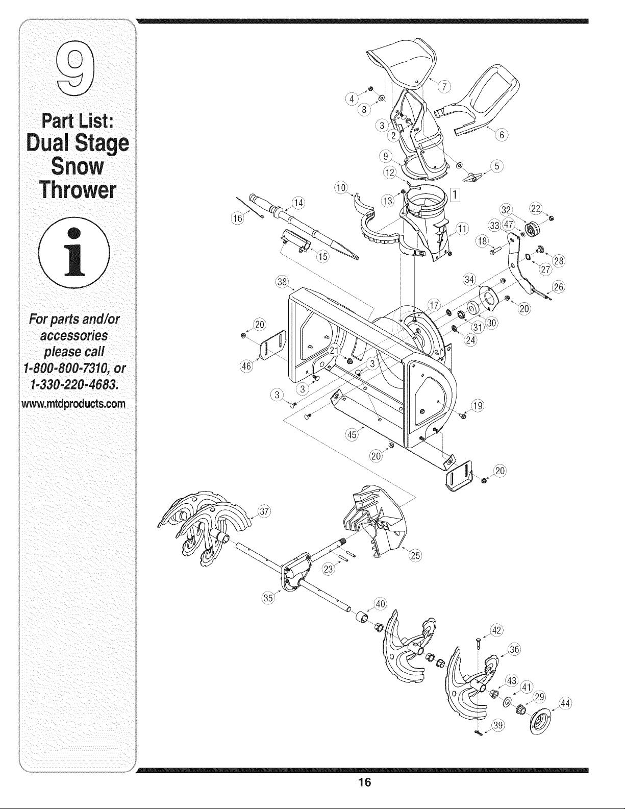
Part L_sl.
For parts and/or
accessories
please call
1-800-800-7310,or
1-330-220-4683.
www.mtdproducts.com
/
f°M
16
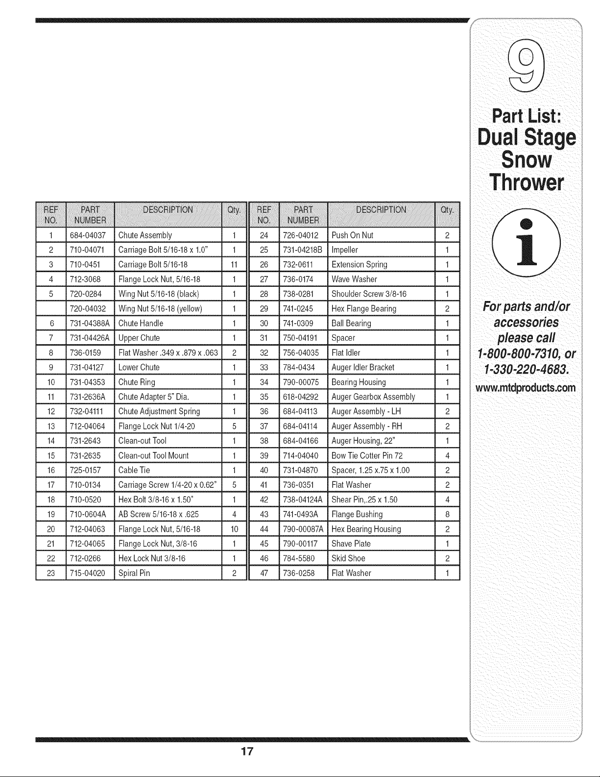
1 684-04037 ChuteAssembly 1 24 726-04012 PushOn Nut 2
2 710-04071 CarriageBolt 5/16-18x 1.0" 1 25 731-04218B Impeller 1
3 710-0451 CarriageBolt 5/16-18 11 26 732-0611 ExtensionSpring 1
4 712-3068 FlangeLock Nut,5/16-18 1 27 736-0174 WaveWasher 1
5 720-0284 Wing Nut5/16-18(black) 1 28 738-0281 ShoulderScrew3/8-16 1
720-04032 Wing Nut5/16-18(yellow) 1 29 741-0245 Hex FlangeBearing 2
6 731-04388A Chute Handle 1 30 741-0309 Ball Bearing 1
7 731-04426A UpperChute 1 31 750-04191 Spacer 1
8 736-0159 FlatWasher.349x .879x .063 2 32 756-04035 Flat Idler 1
9 731-04127 LowerChute 1 33 784-0434 AugerIdler Bracket 1
10 731-04353 Chute Ring 1 34 790-00075 BearingHousing 1
11 731-2636A ChuteAdapter 5" Dia. 1 35 618-04292 AugerGearboxAssembly 1
12 732-04111 •ChuteAdjustmentSpring _ 1 36 684-04113 AugerAssembly- LH 2
13 712-04064 FlangeLock Nut 1/4-20 5 37 684-04114 AugerAssembly- RH 2
14 731-2643 Clean-outTool 1 38 684-04166 AugerHousing,22" 1
15 731-2635 Clean-outTool Mount 1 39 714-04040 BowTie Cotter Pin72 4
16 725-0157 Cable Tie 1 40 731-04870 Spacer,1.25x.75 x 1.00 2
17 710-0134 •CarriageScrew1/4-20 x0.62" 5 41 736-0351 FlatWasher 2
18 710-0520 HexBolt 3/8-16x 1.50" 1 42 738-04124A ShearPin,.25x 1.50 4
19 710-0604A AB Screw5/16-18x .625 4 43 741-0493A FlangeBushing 8
20 712-04063 FlangeLock Nut,5/16-18 10 44 790-00087A Hex BearingHousing 2
21 712-04065 FlangeLock Nut,3/8-16 1 45 790-00117 ShavePlate 1
22 712-0266 HexLock Nut3/8-16 1 46 784-5580 Skid Shoe 2
23 715-04020 Spiral Pin 2 47 736-0258 Fiat Washer 1
PartList:
For parts and/or
accessories
please call
1-800-800-7310,or
1-330-220-4683.
www.mtdproducts.com
17
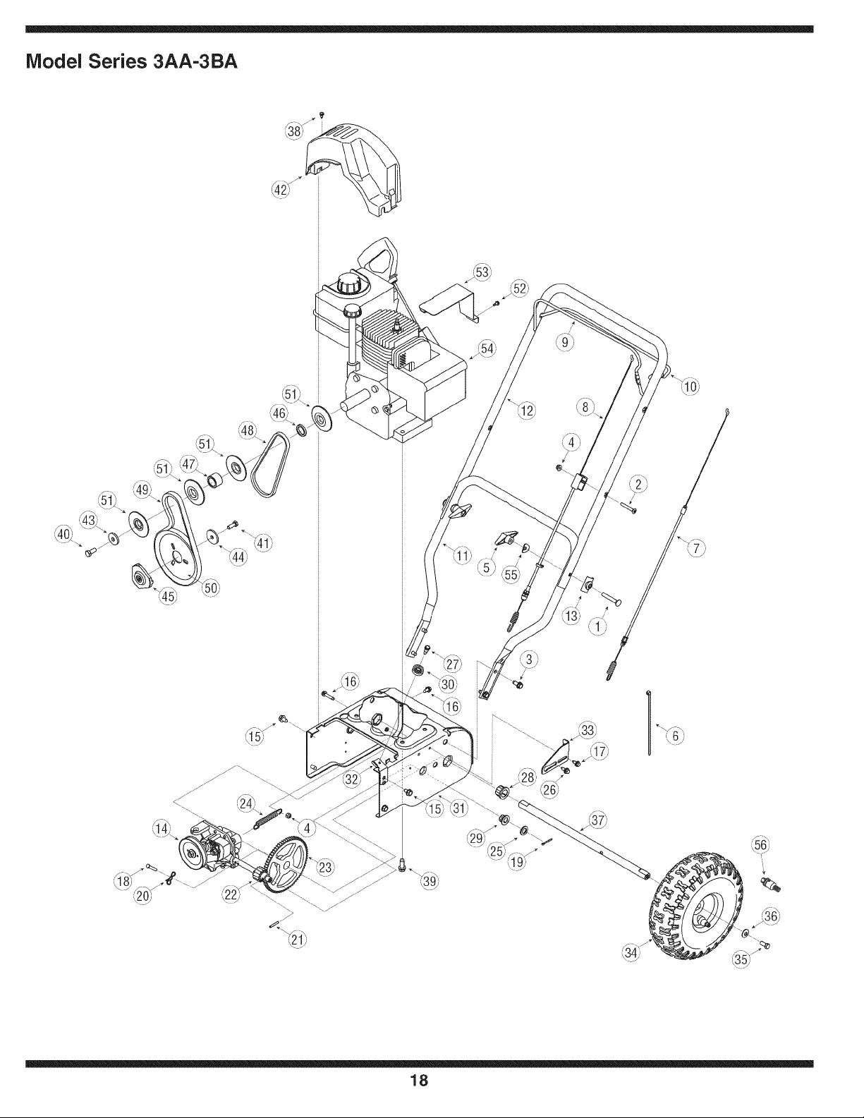
Model Series 3AA-3BA
_J_
_H
18
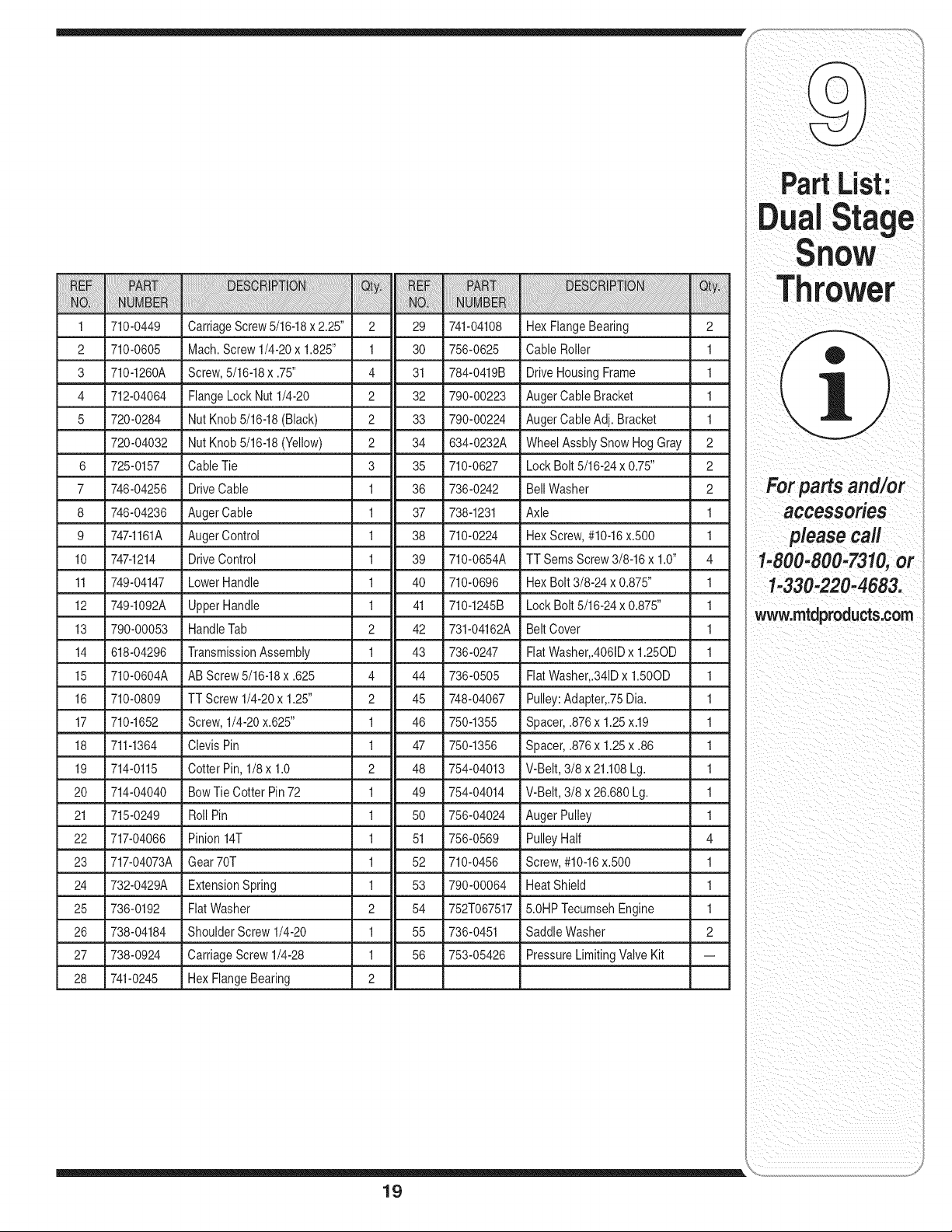
1 710-0449
2 710-0605
3 710-1260A
4 712-04064
5 720-0284
720-04032
6 725-0157
7 746-04256
CarriageScrew5/16-18x 2.25" 2 29 741-04108 Hex FlangeBearing 2
Mach.Screw 1/4-20x 1.825" 1 30 756-0625 Cable Roller 1
Screw,5/16-18x.75" _ 4 31 _ 784-0419B _ Drive HousingFrame _ 1
FlangeLock Nut 1/4-20 2 32 790-00223 AugerCable Bracket 1
NutKnob 5/16-18(Black) 2 33 790-00224 AugerCableAdj. Bracket 1
NutKnob 5/16-18(Yellow) 2 34 634-0232A WheelAssblySnowHog Gray 2
Cable Tie 3 35 710-0627 Lock Bolt 5/16-24x 0.75" 2
DriveCable 1 36 736-0242 BellWasher 2
8 746-04236 AugerCable
9 747-1161A AugerControl
10 747-1214 DriveControl
11 749-04147 LowerHandle
12 749-1092A UpperHandle
13 790-00053 HandleTab
14 618-04296 TransmissionAssembly
15 710-0604A AB Screw5/16-18x .625
16 710-0809 TT Screw1/4-20x 1.25"
17 710-1652 •Screw,1/4-20x.625"
18 711-1364 Clevis Pin
19 714-0115 Cotter Pin, 1/8x 1.0
20 714-04040 BowTie Cotter Pin 72
21 715-0249 Roll Pin
22 717-04066 Pinion 14T
23 717-04073A Gear 70T
24 732-0429A ExtensionSpring
25 736-0192 FiatWasher
26 738-04184 ShoulderScrew 1/4-20
27 _ 738-0924 "Cart ageScrew1/4-28
28 741-0245 Hex FlangeBearing
1
1
1
1
1
2
1
4
2
37 738-1231 Axle 1
38 710-0224 HexScrew,#10-16x.500 1
39 710-0654A TT SemsScrew3/8-16x 1.0" 4
40 710-0696 HexBolt 3/8-24 x 0.875" 1
41 710-1245B Lock Bolt 5/16-24x 0.875" 1
42 731-04162A Belt Cover 1
43 736-0247 FlatWasher,.4061Dx 1.250D 1
44 736-0505 FlatWasher,.341Dx 1.500D 1
45 748-04067 Pulley:Adapter,.75Dia. 1
1 46 750-1355 Spacer,.876x 1.25x.19 1
1 47 750-1356 Spacer,.876x 1.25x .86 1
2 48 754-04013 V-Belt,3/8 x 21.108Lg. 1
1 49 754-04014 V-Belt,3/8 x 26.680Lg. 1
1 50 756-04024 AugerPulley 1
1 51 756-0569 PulleyHalf 4
1 52 710-0456 Screw,#10-16x.500 1
1 53 790-00064 HeatShield 1
2 54 752T067517 5.0HPTecumsehEngine 1
1 55 736-0451 SaddleWasher 2
1 56 753-05426 PressureLimitingValveKit --
2
19
PartList:
Stage
lOW
Thrower
For parts and/or
accessories
please call
1-800-800-7310,or
1-330-220-4683.
www.mtdproducts.com
MANUFACTURER'S LiMiTED WARRANTY FOR
The limitedwarrantyset forth belowisgivenby MTDLLCwithrespectto
newmerchandisepurchasedandusedin the UnitedStates,itsposses-
sionsandterritories.
"MTD"warrantsthisproductagainstdefectsin materialandworkmanship
for a periodof two(2) yearscommencingonthe dateof originalpurchase
andwill, at its option,repairor replace,free of charge,anypart foundto
bedefectivein materialsor workmanship.Thislimitedwarrantyshallonly
applyif this producthas beenoperatedand maintainedin accordance
withthe Operator'sManualfurnishedwith the product,andhas not been
subjectto misuse,abuse,commercialuse, neglect,accident,improper
maintenance,alteration,vandalism,theft,fire,water,ordamagebecause
of otherperilor naturaldisaster.Damageresultingfrom the installationor
useof any part,accessoryor attachmentnotapprovedby MTDfor use
withthe product(s)coveredbythis manualwill voidyourwarrantyas to
any resultingdamage.
Normalwearpartsarewarrantedto befree fromdefectsin materialand
workmanshipfor a periodof thirty (30)daysfromthe dateof purchase.
Normalwearpartsinclude,butare notlimitedto itemssuch as: batteries,
belts,blades,bladeadapters,grass bags, riderdeck wheels,seats,snow
throwerskidshoes,shaveplates,augerspiralrubberand tires.
HOW TO OBTAIN SERVICE: Warranty service is available, WITH
PROOFOF PURCHASE, through your local authorized service
dealer. To locate the dealer in your area, check your Yellow Pages, or
contact MTD LLC at RO. Box 361131,Cleveland, Ohio 44136-0019,or
call 1-800-800-7310or 1-330-220-4683or log on to our Web site at
www.mtdproducts.com.
Thislimitedwarrantydoesnot providecoveragein the followingcases:
a. Theengineor componentparts thereof.These itemsmaycarry a
separatemanufacturer'swarranty.Referto applicablemanufacturer's
warrantyfor termsand conditions.
b. Log splitterpumps,valves,and cylindershavea separateone year
warranty.
c. Routinemaintenanceitemssuch as lubricants,filters, blade
sharpening,tune-ups,brakeadjustments,clutchadjustments,deck
adjustments,andnormaldeteriorationof the exteriorfinishdueto use
orexposure.
d. Servicecompletedby someoneotherthanan authorizedservice
dealer.
e. MTDdoes notextendany warrantyfor productssoldor exported
outsideof the UnitedStates,itspossessionsand territories,except
thosesoldthroughMTD'sauthorizedchannelsof exportdistribution.
f. Replacementpartsthatarenot genuineMTDparts.
g. Transportationchargesand servicecalls.
No impliedwarranty,includingany impliedwarranty of merchant-
ability of fitness for a particularpurpose,applies after the applicable
periodof express written warranty above as to the partsas identi-
fied. No other express warranty, whether written or oral, except as
mentionedabove, givenby any personor entity,includinga dealer
or retailer,with respect to any product,shallbind MTD. Duringthe
periodof the warranty, the exclusive remedyis repairor replacement
of the productas set forth above.
The provisionsas set forth in this warranty providethe sole and
exclusive remedy arising from the sale. MTDshall not be liable
for incidentalor consequential loss or damage including,without
limitation, expenses incurredfor substitute or replacementlawn care
services or for rentalexpenses to temporarily replacea warranted
product.
Somestatesdo not allowtheexclusionor limitationof incidentalor
consequentialdamages,or limitationson howlongan impliedwarranty
lasts,so the aboveexclusionsor limitationsmay notapplyto you.
In noeventshall recoveryof any kind be greaterthan theamountof the
purchasepriceof the productsold.Alterationof safetyfeatures of the
productshall void this warranty. Youassumethe risk and liability for
loss, damage,or injuryto youand your propertyand/orto others and their
propertyarisingout of the misuseor inabilityto use theproduct.
Thislimitedwarrantyshall notextendto anyoneotherthanthe original
purchaseror to the personfor whom itwas purchasedas a gift.
HOWSTATELAW RELATESTO THISWARRANTY: This limitedwar-
rantygivesyouspecificlegalrights,and you mayalso haveother rights
whichvary from stateto state.
IMPORTANT: OwnermustpresentOriginalProofof Purchaseto obtain
warrantycoverage.
MTD LLC, P.O. BOX 361131 CLEVELAND, OHIO 44136-0019; Phone: 1-800-800-7310, 1-330-220-4683