Loading ...
Exhausting cooker hood. The equipment is constructed in
accordance with European Standards and with the requirements
included in the following Directives: 2006/95EC ( Low Voltage
Directive), 2004/108 (Electromagnetic Compatibility).
1 INSTALLATION
Read the instruction manual before installing and/or using the
hood .
In order that the minimum distance between the supporting
surface for the cooking pots on gas hob and low-voltage
components present in the hood is at least 65cm as required by
the regulations in force, it is necessary that the lower part of the
hood is at least 60cm away from the work top.
If the mounting instructions of the gas cooker indicate a wider
distance, respect it. The unit must not be mounted above cookers
tted with top radiant plate.
Respect all the air discharge regulations.
The air must not be discharged in a pipe used to discharge
exhaust fumes produced by gas- fed equipments or fuel-fed
equipments (this does not apply to ltering hoods).
The room must be adequately ventilated when the hoods is used
together with other gas-fed or fuel-fed equipments.
The hood is equipped with all the necessary fastenings for its
installation, which are suitable for most surfaces. Anyway, ask
to a professional to verify that the installation surface is strong
enough. Installation must be carried out by qualied installers
according to present regulations.
For an easy access, it is advisable to move possible furniture
under the installation area. For mounting the hood follow the
illustrations in Fig. 1-2-3.
2 ELECTRICAL CONNECTIONS
This appliance must be connected to an earthed power supply.
Two types of electrical connection can be used:
1. Using a standard plug to be connected to the power cable
and inserted in a mains socket which must be accessible (so
that the plug can be disconnected when servicing is carried
out). Make sure that the plug is accessible also after the
complete installation of the equipment.
2. By means of a xed mains connection, tting a bipolar
switch, which ensures the disconnection, with an opening
distance of the contacts allowing a complete disconnection
on the conditions of the overvoltage III category, according to
installation regulations. The ground connection (yellow-green
wire) must not be interrupted.
Refer to the plate inside the hood for the mains voltage and
frequency ratings.
3 USE
This cooker hood can be employed as exhausting or ltering.
Exhausting (Fig. 4). The carbon lters should not be installed on
the hood in exhausting version.
Kitchen smokes are driven outside through a ue joined to the
exhaust pipe ue connector.
Pipes must be communicating with the exterior of the house. The
diameter of the outlet of the hood is 150mm. A 150-125 reduction
is provided with the hood.
This pipe must not under any circumstances be connected to
cooker, boiler or burner exhaust pipes, etc.
Filtering (Fig. 5). The fumes pass through the carbon lters to be
puried and recycled into the kitchen through a pipe connected
to the outlet of the hood up to the hole in the top of the cabinet.
This hole must be free and communicating with the kitchen.
In the ltering version you must install the two carbon lters on
the sides of the aspirator. To install the carbon lters you must
rst remove the metal grease lters (Fig. 6) and then install
carbon lters by turning them counterclockwise (Fig. 7).
4 OPERATION
The hood is supplied with a multispeed motor.
The hood should be run at low speed under normal conditions
and at higher speeds only when there is a heavy build-up of
fumes or odours.
Ideally, the hood should be switched on as soon as cooking is
started and then kept on until all odours have been eliminated.
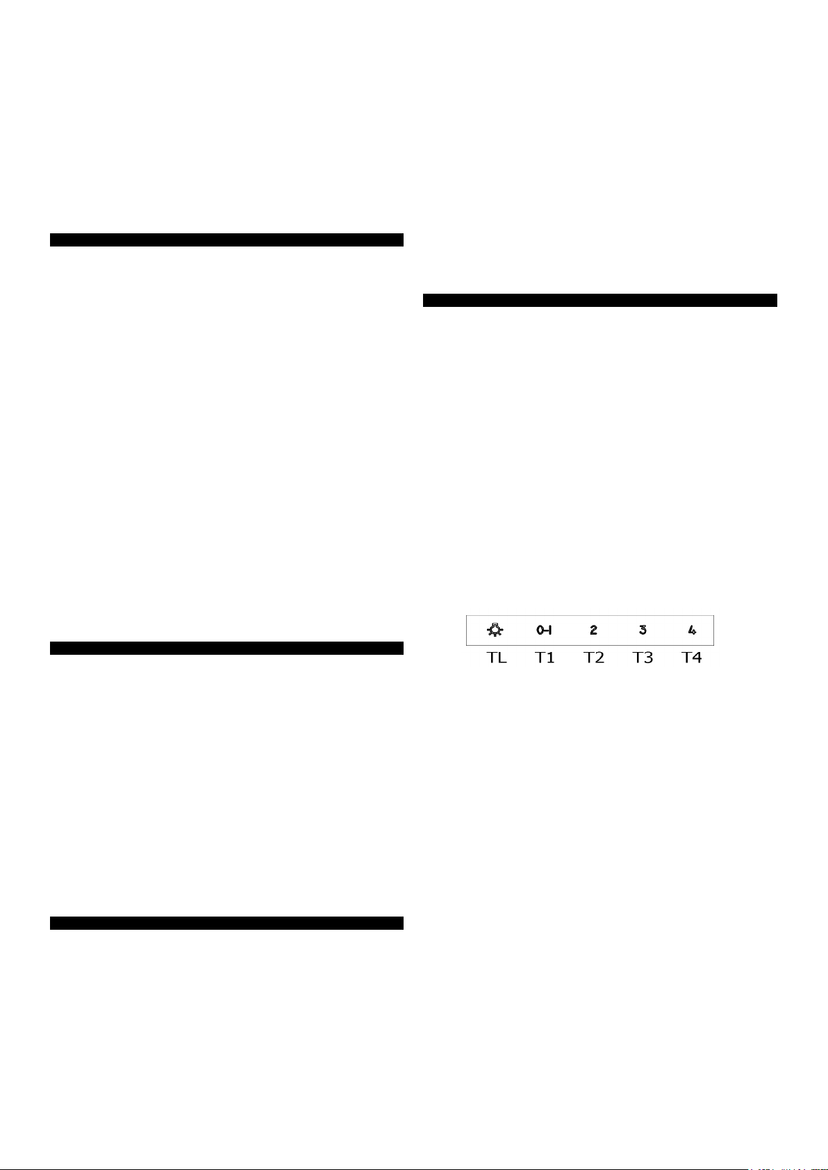
The controls consist of these commands. Press TL to turn on the
light, press T1 to swich on the hood at rst speed and to switch
off the aspirator, press T2-T3-T4 to select functioning speeds.
By pressing of the command T1 the motor starts running at
the 1st speed. The commands T2-T3-T4 switch the motor on
respectively at the 2nd, 3rd and 4th speed. In order to switch the
motor off press T1 once if set at the 1st speed, twice if set at the
2nd, 3rd and 4th speed. With the button T4, select the maximum
speed of the extraction fan for 5 minutes (LED blinking), after
which the extraction fan will automatically switch to the 3rd
speed.
Adjustable and delayed self switching off
While the hood is working, keep the TL command pressed until
all LEDs start blinking. By pressing one of the commands (T1,
T2, T3, T4) you can program the delayed self switching off, as
follows:
T1 corresponds to 5 minutes
T2 corresponds to 10 minutes
T3 corresponds to 15 minutes
T4 corresponds to 20 minutes
Filters maintenance reminder:
Aluminium anti-grease lters
Once the hood is switched off, after 30 hour functioning, all
the LEDs of the speed buttons switch on with a xed light for
30 seconds to remind that aluminium anti-grease lter need
cleaning. To set the timer to zero keep the button T4 pressed
with the aspirator switched off, otherwise the timer will remain set
on 30 hour functioning and the reminder will occur again when
the hood is switched off again.
Charcoal lter (for ltering hoods)
Once the hood is switched off, after 120 hour functioning, all
LEDs blink for 30 seconds to remind that the charcoal lter need
cleaning. To set the timer to zero keep the button T4 pressed with
the aspirator switched off, otherwise the timer will remain set on
120 hour functioning and the reminder will occur again when the
hood is switched off again.
INSTALLATION, OPERATING AND MAINTENANCE INSTRUCTIONS FOR COOKER HOOD IVCU MODELS
230-240 Vac - 50 Hz
Loading ...
Loading ...
Loading ...