GEAppliances.com
0
0
Safety Instructions .......... 2-5
Operating Instru_tions
glidge Burner . ............... 8
Cooktop Vent System .......... 8
Oookware Tips ................ 9
Dual Surfl_ce Unit ............. 8
Features of Your Cooktop ....... 6
Surface Units ............... 7, 8
Temperaun_e Limiter. .......... 8
Care and Cleaning
Control I_a_obs ............... l0
(;lass Cooktop ............ ] 1, ]2
Vent Fiher. .................. ]0
Vent System ................. l0
Imlallation In#ruc¢ions
Ductwork ............. ] %20, 24
Electrical Connections ..... 24-26
Exhaust Blower Ratings ........ 19
Final Assembly ............... 27
Installing the Cooktop ...... 22-24
Installing the Gasket .......... 21
Preparation .............. 15-17
Safety Precautions ............ 13
Unpacking the Cooktop .... 14, 21
Troubleshooting Tips ........ 28
Consumer Support
Consumer Support ........... 32
Product Registration ....... 29, 30
X4';uxantv .................... 31
Write the model and serial
numbers here:
Model #
Serial #
Find these numbexs on a label
under the cooktop, on the side
of the vent ('hambe_:
JP98 9
49-80283 01-05JR
IMPORTANTSAFETYINFORMATION.
READALLINSTRUCTIONSBEFOREUSING.
SAFETYPRECAUTIONS
WARNING- ToREDUCETHERISKOF
FIRE,ELECTRICSHOCKORINJURYTOPERSONS,
OBSERVETHEFOLLOWING:
A. Use this unit only in tile manner intended
by tile manufacturer If you brae questions,
contact the manufi_ctmer.
B. Be%re servicing or cleaning unit, switch
power off at service panel and lock the service
disconnecting means to prevent power flom
being switched on accidentally. When the
service disconnecting means cannot be
locked, securely £1sten a prominent warning
device, such as a tag, to the service panel.
C. Do not use this unit with aW solid-state speed
control device.
D. This unit must be g_ounded.
CAUTION-Forgeneralventilatinguse only.
Donot use to exhausthazardousor explosive
materials and vapors.
WARNING- ToREDUCETHERISKOF
INJURYTOPERSONSIN THEEVENTOFA COOKTOP
GREASEFIRE,OBSERVETHEFOLLOWING*."
A. SMOTHER HAMES with a close-fitting
lid, cookie sheet or metal t_W, then turn off
tile burner BE CAREFUL TO PREVENT
BURNS. If tile flames do not go out
immediately, EXA( _UATE AND CAI,L
THE FIRE DEPARTMENT.
B. NEt'ER PICK UP A FI AMING PAN--
You may be burned.
C. DO NOT USE WATER, including wet
dishcloths or towels--a violent steam
explosion will result.
D. Use an extingldsher ONLY if:
1. You know you have a Class ABC
extinguishe_, and you aheady know
how to opecate it.
2. The fire is small and contained in the
area where it starred.
3. The fire department is being called.
4. You can fight the fire with }our back
to an exit.
* Based on 'Fdtchen Fit esafet) Tips" published
b) NFPA.
WARNING- ToREDUCETHERISKOFA
COOKTOPGREASEFIRE"
A. Never leave sm£me units unattended at hig]l
settings. Boilo\_rs cause smoking and greasy
spillo\_rs that may ignite. Heat oils slowly on
low or medium settings.
B. Always turn the £m ON when cooking at high
heat or when cooking flaming foods.
C. Clean ventilating £ms flequentl> Grease
should not be allowed to accumulate on tim
or filter.
D. Use proper pan size. Alwa) s use cookware
appropriate for the size of the surfi_ce
element.
WARNING- TOREDUCETHERISKOF
FIRE,ELECTRICSHOCKORINJURYTOPERSONS,
OBSERVETHEFOLLOWING:
A. Installation work and electrical wirh_g must
be done by qualified person(s) in accordance
with all applicable codes and standards,
including fire-rated construction.
B. Sufficient air is needed for proper combustion
and exhausting of gnses through the flue
(chimney) of fuel burning equipment to
prevent back dcafting. Follow the headng
equipment manufacturer's glddeline and
safety standards such as those published by the
National Fire Protection Association (NFPA),
and the American Society for Heating,
Refrigeration and Air Conditioning Engineers
(ASHRAE), and the local code authorities.
C. When cutting or drilling into wall or ceiling,
do not damage electrical wiring and other
bidden utilities.
D. Ducted rims must always be vented to the
outdoors.
WARNING- ToREDUCETHERISKOF
FIRE,USEONLYMETALDUCTWORK.
Do not attempt to repair or replace any
part of your downdraft cooktop unless it is
specifically recommended in this manual.
All other servicing should be referred to a
qualified technician.
2
GEAppliances.com
WARNING!
For your safe_, the information in this manual must be followed to minimize the risk of fire or
explosion, electric shock, or to prevent property damage, personal injury, or loss of life.
SAFETYPRECAUtiONS
When using electrical appliances, basic safety precautions should be foflowed, including
the following:
Be sure your appliance is properly installed
and grounded by a qualified technician
in accordance with local codes and the
provided installation instructions.
Haxe the installer show you the location
of the circuit breaker or Rise. Mark it for
easy reference.
Do not leme children alone--children
should not be left alone or unattended
in an area where an appliance is in use.
They should nexer be allowed to sit or
stand on any part of the appliance.
Teach children not to play xx6ththe
controls or any other part of the cooktop.
Do not allow anyone to climb, stand or
hang on the cooktop.
CAUTION: Items of interest to
children should not be stored in cabinets
aboxe a cooktoi>--children climbing on the
cooktop to reach items could be seriously
hljured.
Always kee I) combnsdble wall coxefings,
curtains or drapes a safe distance fiom
your cooktop.
Always kee I) dish towels, dishcloths, pot
holders and other linens a safe distance
away from your cooktop.
Always kee I) wooden and plastic utensils
and canned food a safe distance away flom
your cooktop.
Never wear loose-fitting or hanging
garments while using tile appliance.
Flammable mamrial could be ignimd if
brought in contact with hot surface units
and may cause severe bnrns.
Use only dU pot holders--moist or damp
pot holders on hot surfaces may result in
buries ftom steam. Do not let pot holders
touch hot surface units. Do not use a towel
or other bulky cloth. Such cloths can catch
fire on a hot snrPace unit.
For your safety, nexer use your appliance
for wanning or heating the room.
Do not use water on grease fires. Nexer
pick up a flaming pan. Turn tim controls
of£ Smother a flaming pan on a surtZace
unit by coxering tile pan complemly with
well-fitting lid, cookie sheet or fiat tr W.
Use a muld-pull)ose dU chemical or
tbam-tvpe extinguisher
Flaming grease outside a pan can be
put out by coveting with baking soda o_,
if available, by using a multi-purpose dU
chemical or foam-type fire extinguisher
COOKMEATANDPOULTRYTHOROUGHLY...
Cookmeat andpoultry thoroughly--meat to atleast an INTERNALtemperatureof 160°Fandpoultrytoat least
an INTERNALtemperatureof 180°ECookingto thesetemperaturesusuallyprotectsagainstfoodbomeillness.
3
IMPORTANTSAFETYINFORMATION.
READALLINSTRUCTIONSBEFOREUSING.
WARNING!
SAFETYPRECAUTIONS
Do not let cooking grease or other
flammable materials accumulate on
the cooktop.
Do not touch surface units. These surthces
may be hot enough to bum exen fl_ough
they are dark in color During and after
use, do not much, or let clothing or oilier
flammable materials contact fl_e surlhce
units or areas nearby the surthce units;
allow sufficient time for cooling first.
Potentially hot surthces include the
cooktop and areas facing the cooktop.
To minimize the possibili U of bums,
ignition of flammable materials and
spillage, the handle of a container
should be turned toward rite cenmr of
the cooktop without extending oxer
any nearby snifitce tlnits.
Always tuna the surthce unit control to off
before removing the cookware.
Use proper pan size--Select cookware
having fiat bottoms large enough to coxer
the surlhce unit heating element. The use
of undersized cookware will expose a
portion of the snrthce unit to direct
contact and m W resnh in ignition of
clothing. Proper relationship of cookware
to burner will also improxe efficienc>
Nexer leme snr/_ace units unattended at
high heat settings. Boiloxers cause smoking
and greasy spilloxers that may catch on fire.
Only certain types of glass, glass/ceramic,
earthenware or other glazed containers are
suitable for cooktop cooking; others may
break because of the sudden change in
temperature.
Kee I) an eye on foods being fried at high
or medium high heat settings.
Foods %r flTing should be as dU as
possible. Frost on fiozen foods or moisture
on flesh tbods can cause hot fat to bubble
up and oxer the sides of the pan.
Use little t_atfor eft_ctixe shallow or deeI>
tht flTing. Filling the pan too rill oflht can
cause spilloxers when tbod is added.
If a combination of oils or Pats will be used
in flTing, stir together before heating, or as
featsmeh slowly.
Always heat/aat slowly and watch as it heats.
Use a deep tht them/ometer whenexer
possible to pre_ent o_eflleating fi_t beyond
the smoking point.
Nexer ttw,to moxe a pan of hot fi_t,
especially a deep tht flyer _'ait until the
fht is cool.
Do not store flammable materials near
the cooktop.
Kee I) the xent grille and grease fihers clean
to maintain good xenting and to axoid
grease fires.
Do not store or use combustible materials,
gasoline or other flammable vapors and
liquids in the vicinity of this or any
appliance.
Clean only parts listed in this Owner's
Manual.
Do not leme paper products, cooking
utensils or food on the cooktop when not
in use.
Kee I) cooktop clean and flee of
accunmlation of grease or spilloxers
which may ignite.
Nexer heat unopened %od containers.
Pressure buildup may make container
burst and cause inju U.
Nexer lemejars or cans of fat drippings
on or near your cooktop.
4
GEAppliances.com
RADIANTSURFACEUNITS
Use care when touching the cooktop. Theglass surface of the cooktop will retain heat after the
controls have been turned off.
Avoid scratching fl_e glass cooktop.
The cooktop can be scratched with items
such as shm]) instruments, Hngs or other
jeweh y and Hx_ts on clothing.
Larg_ scratches or impacts to glass
cooktops can lead to broken or
shattered gJass.
Never use d_e glass cooktop surfi_ce as
a cutting board.
Do not place or store items on top of the
glass cooktop surfi_ce when it is not in use.
Be carefld when placing spoons or oflmr
stirring utensils on glass cooktop surface
when it is in use. They m W become hot
and could cause bums.
Avoid heating an empty pan. Doing so may
damag> the cooktop and the pan.
Do not allow watel, oilier liquids or grease
to remain on the cooktop.
To minimize the possibility of buI_lS, always
be certain that the controls for all suiiCace
units are at the off'position and the entire
glass surface is cool hefore attempting to
clean the cooktop.
Do not operate fl_e glass surface units if
the glass is broken. Spillo_ers or cleaning
solution m W penetrate a broken cooktop
and create a risk of electrical shock.
Contact a qualified technician immediately
should your g']ass cooktop become hroken.
Clean the cooktop with caution, ff a wet
sponge or c]odl is used to wipe spills on
a hot surt_ace unit, be carefld to axoid
steam bums. Some cleansers can produce
noxious filmes if applied to a hot surface.
NOTE,"_4:erecommend dmt you moid
wiping any suiiaace unit areas until they
have cooled and the indicator light has
gone off: Sugar q)ills ate the exception to
this. Please see Cleaning the Glass Cooktop
in the Careand Cleaning sect.ion.
When dm cooktop is cool, use only
CERAIVlA BRYTE _' Ceramic Cooktop
Cleaner and the CERAMA BRYI'E _
Cleaning Pad to clean the cooktop.
To axoid possible damag_ to dm cooking
surt_ace, do not apply the cleaning cream
to the glass surface when it is hot.
Atter cleaning, use a di T cloth or paper
towel to remox> all the cleaning cream
residue.
Read and follow all instructions and
warnings on die cleaning cream labels.
READANDFOLLOWTHISSAFETYINFORMATIONCAREFULLY.
SAVETHESEINSTRUCTIONS
5
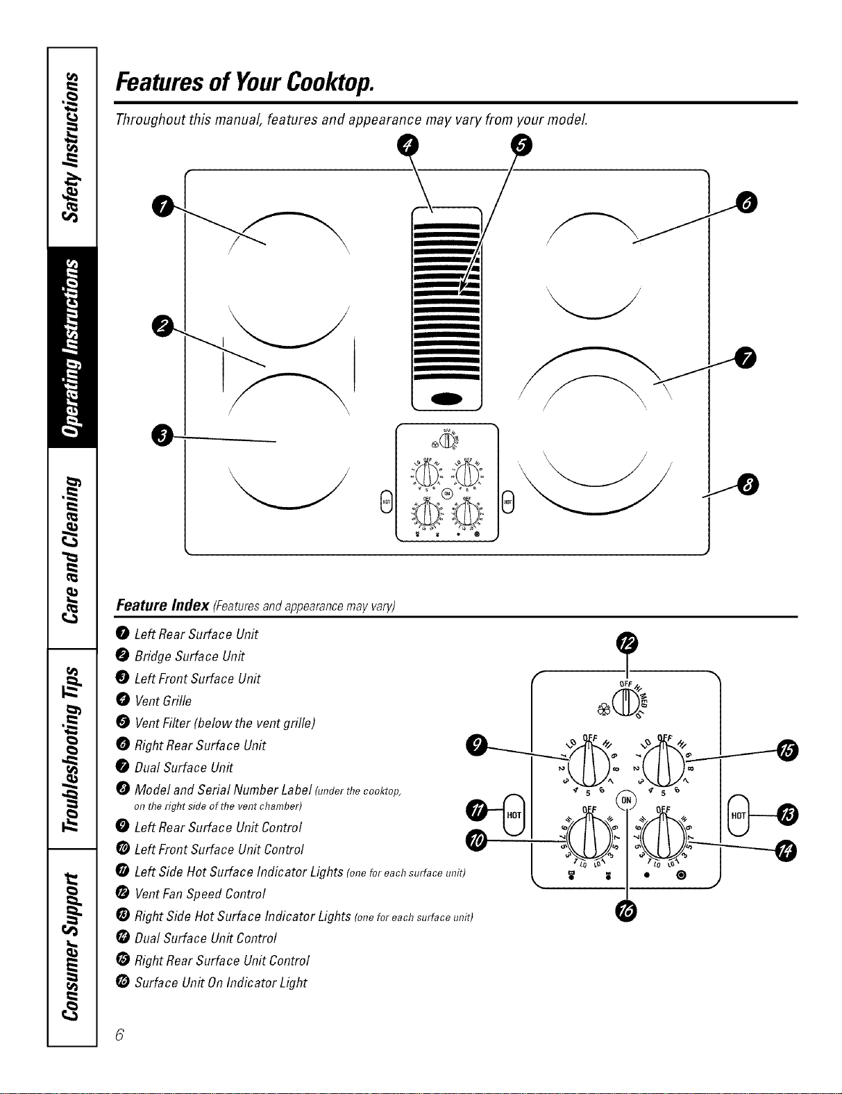
Featuresof YourCooktop.
Throughout this manual, features and appearance may vary from your model.
0
0
__
m
_ ®
0
Feature/lldex (Features and appearance may vary)
0 Left RearSurface Unit
7
0 Bridge Surface Unit
Left Front Surface Unit
0 VentGrille _
VentFilter(belowtheventgrille) -I = "_ I
i
0
oo.o,,._,o_oo.,r ;LU2:;LU!: I
0 Model and Serial Number Label (underthe cooktop, A _ I _ 5 _ _ _ s _ I
o,,the,ig,,t_i_eo_,,__,,_,,_,,b_,_ tB'h--I...II o_,_ o_'_ I(...')_f_
0 Left RearSurface Unit Control _ U I _/1'_=£4'_ ICJ
*LeftSideHotSurfacelndicatorLights(o,,eforeochsurfoceunit) L '1"_'I ®L'_ J --
VentFanSpeed Control
RightSide Hot Surface Indicator Lights (oneforeachsurfaceunit) 0
DualSurface Un#Control
RightRear Surface Unit Control
Surface Un#On Indicator Light
Usingthesurfaceunits. GEAppliances.com
q
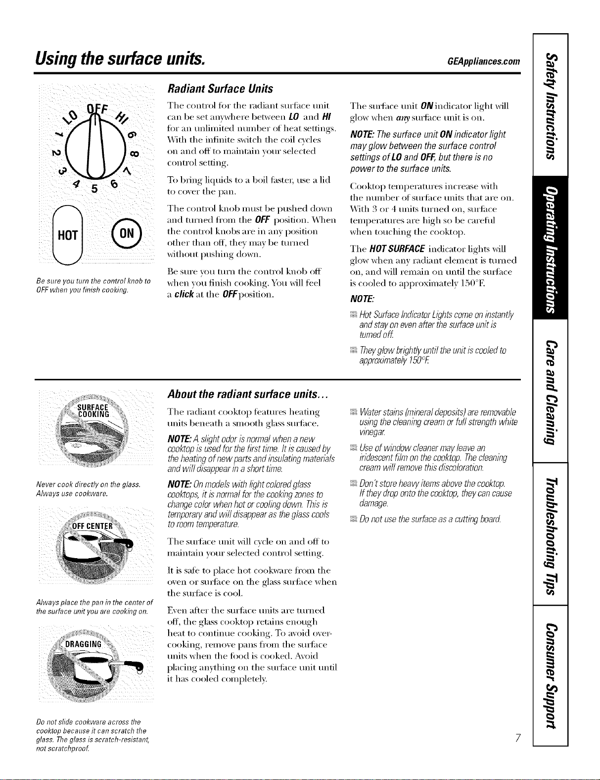
Be sure _ou turn me control KI?ODro
OFFwhen you finish cooking.
Radiant Surface Units
The control tor the radiant surfi_ce unit
can be set anywhere between LO and HI
tot an unlimited number of heat settings.
With tile infinite switch tile coil cycles
on and off to maintain your selected
control setting.
To bring liquids to a boil tilstei; use a lid
to cover tile pan.
The control knob must be pushed down
and turned fl'om tile OFFposition. _._l/ell
the control knobs are in any position
other than off, they may be turned
without pushing down.
Be sure you mrn tile control knob off
when you finish cooking. You will feel
a click at the Of Fposition.
Tile smthce unit ON indicator light will
glow when a,ty s/mfiace unit is on.
NOTE: Thesurface unit ON indicator light
may g/ow between the surface control
settings of LO and OFF,but there is no
powerto the surface units.
Cooktop temperatures increase with
tile nmnber _ff surti_ce milts that are on.
With 3 or 4 milts turned on, sm'fi_ce
temperatures are high so be carefifl
when touching the cooktop.
Tile HOTSURFACEindicator lights will
glow when any radiant element is turned
on, and will remain on until tile s/m'hce
is cooled to approximately 150°E
NOTE:
HotSurfaceIndicatorb)hts comeonlhstantly
andstayonevenafterthesurfaceunitis
turnedoff
Theyglowbwht/yuntiltheunitiscodedto
approximately150°E
Never cook directly on the glass.
Always use cookware.
Always place the pan in the center of
flTesurface unit you are cookfl}g on.
About the radiant surface units...
Tile radiant cooktop teatm'es heating
units beneath a smooth glass surfilce.
NOTE:A sh)htodorisnormalwhena new
cooktopIsusedforthefkst time.It iscausedby
theheatingofnewpartsandlhsu/atlhgmaterb/s
andwi//disappearin ashorttl_ne.
NOTE:Onmodelswithb)htco/oredg/ass
cooktops,it isnormalforthecookbgzonesto
changecolorwhenhotorcodingdown.Thisis
temporaryandwi//disappearastheglasscools
toroomtemperature.
Tile smtace trait will cycle on and off to
maintain your selected control settin ,
It is sate to place hot cookware fl'om tile
o'_en ,(:,I"StlKlilce on tile glass Stllq'ilce when
the SUlqfhce is cool.
Even after tile surtiace units are turned
off, tile glass cooktop ret;fins enough
heat to contintle cooking. To avoid ovei _
cooking, remove pans ti'om the smti_ce
milts when tile load is cooked. Avoid
placing anything on the s/m'iace unit tmtil
it has cooled completely:
Waterstains(minera/deposits)areremovab/e
usingthecleaningcreamorfullstrengthwhite
whegar
Useofwlhdowcleanermayleavean
indescentfilmonthecooktop.Thec/eamhg
creamwi//removethisdiscoloration.
Don'tstoreheavyitemsabovethecooktop.
If theydropontothecooktop,theycancause
damage.
Donotusethesurfaceasacuttinghoard
Do not sfide cookware across the
cooktop because it can scratch the
glass. Theglass is scratch-resistant,
not scratchproo_
Usingthesurfaceunits.
O[.FOF
tZo O:
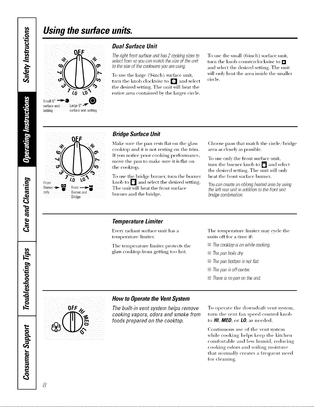
Dual Surface Unit
Therightfrontsurfaceunithas2cooklbgsizesto
selectfromsoyoucanmatchthes/2eoftheunit
tothesl2eofthecookwareyouareusing.
To use the lmge (9-inch) suriime unit,
turn tile knob clockwise to [] and select
the desired setting. The unit will heat the
entire area contained by the linger circle.
To use tile small (6-inch) surfi_ce unit,
ttli'n the knob counterclockwise to []
and select the desired setting. The unit
will only heat the area inside the smaller
circle.
setting surfaceunitsetting
0 F
F LO L_
Bru°ii/er-tb-_ Froltt._,,-_•
only Burner and
Bridge
Bridge Surface Un#
Make sure tile pan rests fiat on tile glass
cooktop and it is not resting on tile trim.
If you notice poor cooking pedimnance,
move the pan to make sure it is flat on
tile cooktop.
To use the bridge burnei; tunl the burner
knob to [] and select the desired setting.
The unit will heat the fi'ont suil'ilc'e
burner and tile bridge.
Choose pans that match tile circle/bridge
area as closel) as possible.
To use onlx tile fl'ont stm'i_ce unit,
turn tile burner knob to [] and select
the desired setting. The unit will only
heat tile front surli_ce burner.
Youcan createan oblongheatedareaby using
the left rear unit in addition to the front unit
bndgecomblbation.
Temperature Limiter
Every radiant surli_ce unit has a
temperature limited:
Tile temperature limiter protects tile
glass cooktop ti'om getting too hot.
Tile temperature limiter may cycle tile
units off fin" a time if':
Thecooktopis on while cooking.
Thepan boi/sdry
Thepan bottomis not f/a_
Thepan is off-center
Thereisno pan on theuniL
How to Operate the Vent System
The built-in vent system helps remove
cooking vapors, odors and smoke from
foods prepared on the cooktop.
To operate tile downdrafl vent system
turn tile xent tim speed control knob
to HI, MED, or LO, as needed.
Continuous use of tile vent svstem
while cooking helps kee I) the kitchen
comtortable and less humid, reducing
cooking odors and soiling moisture
that normally creates a frequent need
tot cleaning.
8
Selectingtypesof cookware. CEA,,lia.ces.com
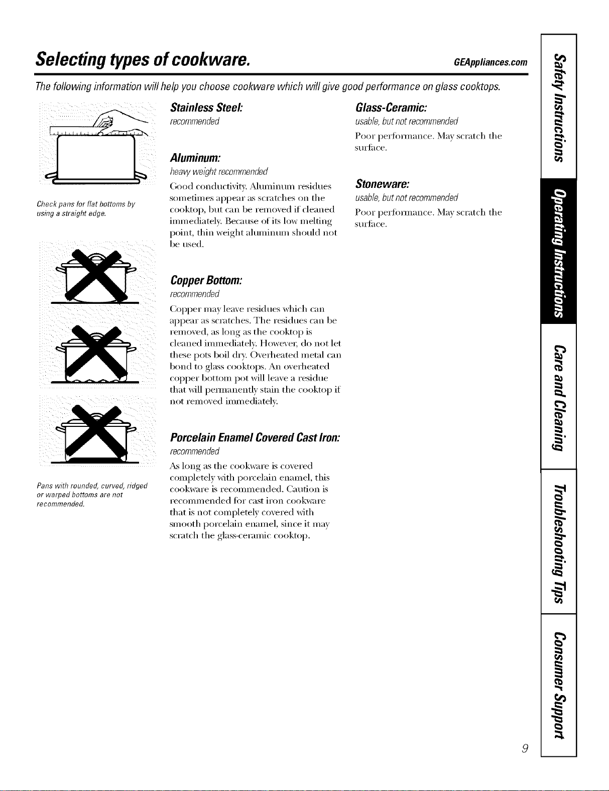
Thefollowing information will help you choose cookware which will give good performance on glass cooktops.
Stainless Steel'.
Aluminum:
heavy weight recommended
(;ood conducfivit): _Muminum residues
Check pans for flat bottoms by SOln etimes apl)ear as scratches on the
using a straight edge. cooktop, but can be removed if deaned
immediately: Because ofits low melting
point, thin weight aluminum should not
be used.
Glass-Ceramic:
usable,butnotrecommended
Poor i_erfi)mmn('e. Ma) scratch the
StlI'J[il ce,
Stoneware:
usable, but not recommended
Poor perfimnance. Ma) scratch the
StlI'J[il ce.
CopperBottom:
recommended
CoI_per may leave residues which ('_lil
appear as scratches. The residues can be
reI/loved, as long as the cooktop is
cleaned immediately. However; do not let
these pots boil dry: Overheated metal can
bond to glass cooktops. An overheated
COl)per bottom pot will leave a residue
that will pemmnently stain the cooktop if
not removed immediately.
Pans with rounded, curved, ridged
or warped bottoms are not
recommended.
Porcelain EnamelCoveredCastIron:
recommended
_&_long as the cookware is covered
complemly with porcelain enamel, this
cookware is recommended. Caution is
recommended for cast iron cookware
that is not completely covered with
smooth porcelain enamel, since it may
scratch the glass-ceramic cooktop.
9
Careand cleaning ofthecooktop.
Be sure electrical power is off and all surfaces are cool before cleaning any part of the cooktop.
Vent System
Before cleaning the vent grille, be sure
the exhaust blower is turned off.
To clean the vent grifle, remove it fl'om
the cooktop by lifting it up and off.
Wipe with a dmn I) cloth. If necessary,
the vent grille can be washed in the sink.
Use dishwashing liquid fi)r cleaning.
Do not use abrasive cleanex_. They will
damage the vent grille's finish.
Do not clean the vent grille in the
dishwashex:
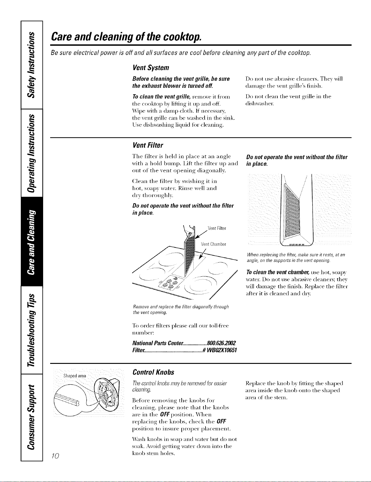
Vent Filter
The filter is held in place at an angle
with a hold bump. I,ilt the filter up and
out of the vent opening diagonally.
Clean the filter by swishing it in
hot, soapy water. Rinse well and
(h'x thoroughl).
Do not operate the vent without the filter
in place.
Donot operatethevent withoutthefilter
in place.
Vent Filter
VentChamber
When replacing the filter, make sure it rests, at an
angle, on thesupports in the vent opening.
Toclean the ventchamber, use hot, soap)'
watet: Do not use abrasive cleane_; they
will damage the finish. Replace the filter
after it is cleaned and dry:
Remove and replace flTe filter diagonally through
the vent opening.
To order filte_s please call our toll-ti'ee
n t/I/lbeI':
NationalPartsCenter....................800.626.2002
Filter................................................# WBO2X10651
Control Knobs
Shapedarea
Thecontrolknobs maybe removedfor easier
cleanlbg.
Before removing the knobs fl)r
cleaning, please note that the knobs
are in the OFFposition. When
replacing the knobs, check the OFF
position to insure proper placement.
10
X_sh knobs in soap and water but do not
soak. A\oid getting water down into the
knob stem holes,
Replace the knob b) fitting the shaped
area inside the knob onto the shaped
area of the stem.
Cleaningtheglasscooktop. CEAppliancescom
Cleanyourcooktopafter
eachspill. Use CERAMA
BRYTE®CeramicCooktop
Cleaner.
Normal Daily Use Cleaning
ONLY use CEIL_dMA BRYTE _'Ceranfic
Cooktop Cleaner on the glass cooktop.
Other creams ma_ not be as eflectixe.
To inaii_taii_ and protect the SUlti_ce _ff
your glass cooktop, t011ow these steps:
, l
[] Before using the cookto ) fi)r the
fi_t time, clean it with CEI_d'dA
BRYTE ')Ceralnic Cooktop Cleanei:
This helps protect the top and
inakes clean-up easiei:
[] Dail) tlse of CEl_z_d_/]_ BRYTE _:'
(2eramic ('xx)ktop Cleaner will help
kee I) the cooktop looking new.
[] Shake the clealfing cream well.
Appl_ a few drops of CEI_dMA
BRYTE e_Ceramic Cooktop Cleaner
directly to the cooktop.
[] Use a p_}per towel or CEIL&MA
BRYTE _"Cleaning Pad fi)r Ceran]ic
Cooktops to clean the entire
cooktop StlI'J[ilce.
[] Use a dry cloth or paper towel
to relnove all cleaning residue.
No need to rinse.
NOTE: It/a veryimportant that you DO NOT
heat the cooktop until it has been cleaned
thorough/_
iii/ / / /L ¸¸
( 2
Usea CERAMABRYTE*_Cleaning
Pad for Ceramic Co&tops or a
Scetch-Brite ®Multi-Purpose No
Scratch blue scrub pad.
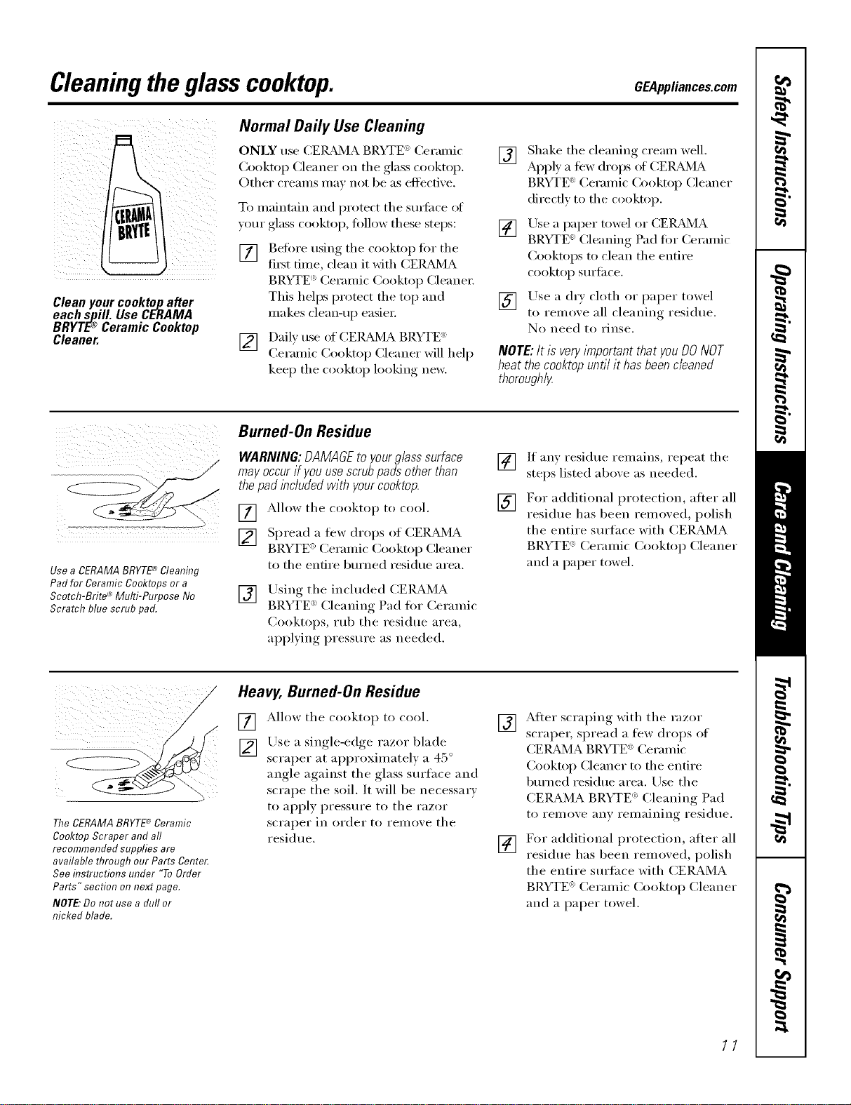
Burned-On Residue
WARNING:DAMAGEtoyourg/asssurface
mayoccurif youusescrubpadsotherthan
thepadbciudedwith yourcooktop.
[] Allow the cooktop to cool.
[] Spread a few drops of CER,AAMA
BRYTE _>(]eralnic Cooktop (]leaner
to the entire burned residue area.
[]
Using the inchlded CEIL_MA
BRYTE _>Cleanin- Pad for Ceramic
Cooktops, rub the residue area,
ali))lxing,, pressure as needed.
[] If any residue renmins, repeat the
steps listed above as needed.
[] For additional protection, after all
residue has been relnoxed, polish
the entire surfi_ce with CERAMA
BRYTE ') (_eralnic Cooktop Cleaner
and a paper towel.
TheCERAMABRYTE'*_Ceramic
Co&top Scraper and aft
recommended supplies are
available through our Parts Center.
See instructions under "To Order
Parts" section on next page.
NOTE:Do not use a duffor
nicked blade.
Heavy, Burned-On Residue
[] Allow the cooktop to cool.
[] Use a single-edge razor blade
scraper at approxinmtely a 45 °
angle against the glass surface and
scrape the soil. It will be necessary
to apply pressure to the razor
scraper in order to remove the
residue,
[] After scraping with the razor
scraper, spread a few drops of
(%l_d'dA BRYTE <'_Ceramic
()_oktop Cleaner to the entire
burned residue area. Use the
CERAMA BRYTE ')Cleaning Pad
to remove any renmilfing residue.
[] For additional protection, alter all
residue has been relnoxed, polish
the entire surtace with CERAMA
BRYTE ')Ceralnic Cooktop Cleaner
and a paper towel.
11
Cleaningtheglasscooktop.
Metal Marks and Scratches
[] Be careflll not to slide pots and
pans across your cooktop. It will
leave metal markings on the
cooktop S/lI'J[_lce.
These marks are remowd)le using
the CERAMA BRYTE (')Ceramic
Cookto I) Cleaner with the
CERAMA BRYTE 6)Cleaning Pad
ti_r Ceramic Cooktoi)s.
[] If pots with a thin oxerla) of
aluminum or COl)per are allowed
to boil dr):, the overlay may leave
black discoloration on the
cooktop.
This should be removed immediately
before heating again or the
discoloration may be permanent.
WARNING: Carefullycheck the bottom
of pans for roughness that would scratch
the cooktop.
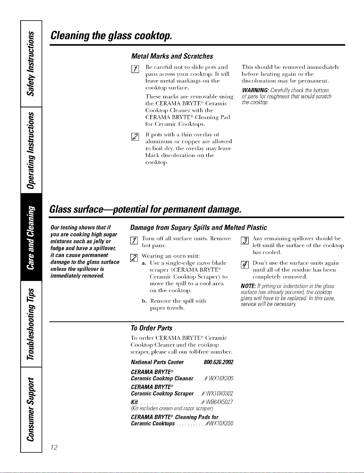
Glasssurface--potential forpermanent damage.
Our testing shows that if
you are cooking high sugar
mixtures such as jelly or
fudge and have a spillover,
it can cause permanent
damage to the glass surface
unless the spillover is
immediately removed.
Damage from Sugary Spills and Melted Plastic
[] Turn off all surthce units. Remove
hot pans.
[] Wearing an oven mitt:
a. Use a single-edge razor blade
scraper (CEI__MA BRYTE :
Ceramic Cooktop Scraper) to
move the spill to a cool area
on the cooktop.
b. Remove the spill with
paper towels.
[] An) remaining spillover should be
left until the surfi_ce of the cooktop
has cooled.
] Don't use the surtace units again
until all of the residue has been
completely removed.
NOTE: If pitting or indentation lb the glass
surface has already occurred, the cooktop
glass will have to be replaced In this case,
service wifl be necessarg
To Order Parts
To order CERAMA BRYTE _ Ceramic
Cooktop Cleaner and the cooktop
scrape_; please call our toll-free number:
National Parts Center 800.626.2002
CERAMABRYTE®
CeramicCooktopCleaner.... # WXIOX300
CERAMABRYTE®
CeramicCooktopScraper . .# WXIOX0302
Kit ...................... # WB64XS027
(Kitincludescreamandrazorscraper)
CERAMABRYTE® CleaningPadsfor
CeramicCooktops........... #WXTOX350
12
Ilnstallation
nstruct ons
Radiant
Downdraft Cooktop
I If you have questions, call 800.GE.CARES (800.432.2737) or visit our Website at: GEAppliances.com
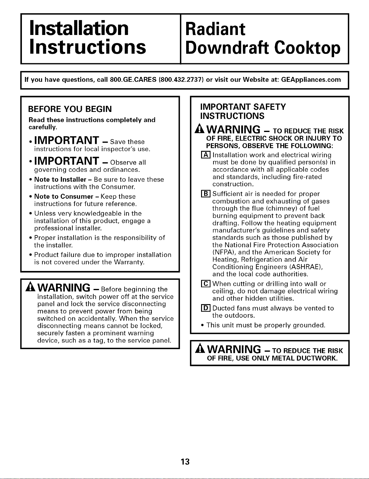
BEFORE YOU BEGIN
Read these instructions completely and
carefully.
• IMPORTANT - Savethese
instructions for local inspector's use.
• IMPORTANT - Observeall
governing codes and ordinances.
• Note to Installer - Be sure to leave these
instructions with the Consumer.
• Note to Consumer - Keep these
instructions for future reference.
• Unless very knowledgeable in the
installation of this product, engage a
professional installer.
• Proper installation is the responsibility of
the installer.
• Product failure due to improper installation
is not covered under the Warranty.
WARNING - Beforebeginning the
installation, switch power off at the service
panel and lock the service disconnecting
means to prevent power from being
switched on accidentally. When the service
disconnecting means cannot be locked,
securely fasten a prominent warning
device, such as a tag, to the service panel.
IMPORTANT SAFETY
INSTRUCTIONS
WARNING - ToREOUCETHERISK
OF FIRE, ELECTRIC SHOCK OR INJURY TO
PERSONS, OBSERVE THE FOLLOWING:
[] Installation work and electrical wiring
must be done by qualified person(s) in
accordance with all applicable codes
and standards, including fire-rated
construction.
[]
[]
Sufficient air is needed for proper
combustion and exhausting of gases
through the flue (chimney) of fuel
burning equipment to prevent back
drafting. Follow the heating equipment
manufacturer's guidelines and safety
standards such as those published by
the National Fire Protection Association
(NFPA), and the American Society for
Heating, Refrigeration and Air
Conditioning Engineers (ASHRAE),
and the local code authorities.
When cutting or drilling into wall or
ceiling, do not damage electrical wiring
and other hidden utilities.
[] Ducted fans must always be vented to
the outdoors.
• This unit must be properly grounded.
I_k WARNING - ToREOUCETHERISKI
I
OF FIRE, USE ONLY METAL DUCTWORK.
I
13
Installation Instructions
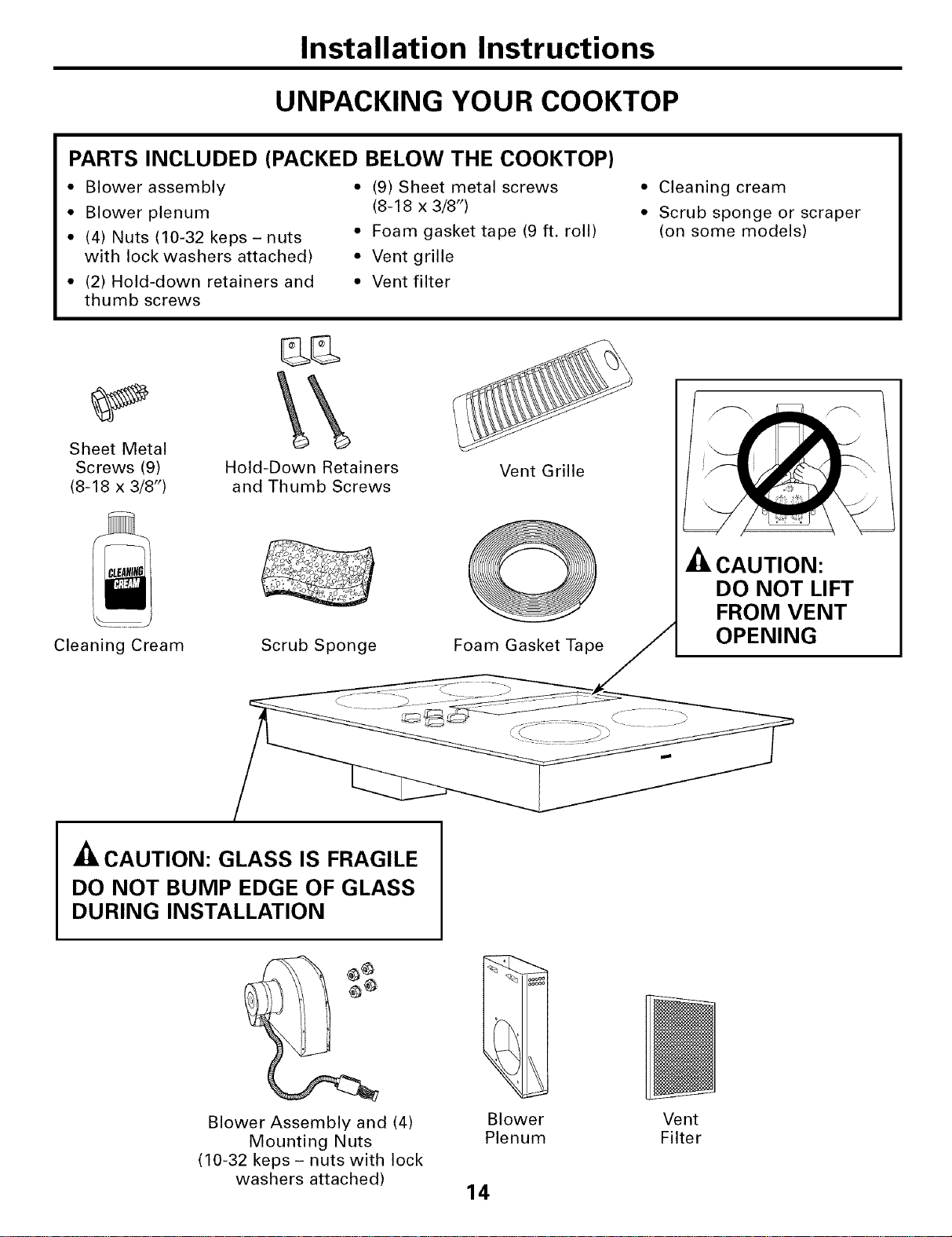
UNPACKING YOUR COOKTOP
PARTS INCLUDED (PACKED BELOW THE COOKTOP)
* Blower assembly
* Blower plenum
• (4) Nuts (10-32 keps- nuts
with lock washers attached)
• (2) Hold-down retainers and
thumb screws
• (9) Sheet metal screws
(8-18 x 3/8")
• Foam gasket tape (9 ft. roll)
• Vent grille
• Vent filter
• Cleaning cream
• Scrub sponge or scraper
(on some models)
Sheet Metal
Screws (9)
(8-18 x 3/8")
Cleaning Cream
Hold-Down Retainers
and Thumb Screws
Scrub Sponge
Vent Grille
O
Foam Gasket Tape
-_ CAUTION:
DO NOT LIFT
FROM VENT
OPENING
A
• ILCAUTION: GLASS IS FRAGILE
DO NOT BUMP EDGE OF GLASS
DURING INSTALLATION
Blower Assembly and (4)
Mounting Nuts
(10-32 keps - nuts with lock
washers attached)
Blower Vent
Plenum Filter
14
Installation Instructions
PREPARATION
TOOLS AND MATERIALS
YOU WILL NEED
• Saw
• Flat blade screwdriver
• Electrician's pliers
• Duct tape
• Measuring tape or scale
• Carpenter's square
• 7/16" wrench or socket set
• Drill and drill bit
• Sheet metal screws
• Junction box*
• 3/4" flexible conduit*
• Electrical wire per local code*
• Wire nuts*
• Duct work
*NOTE: Electrical installation kit JXCK89
may be ordered separately and includes all
the parts necessary to connect the cooktop
to typical rough-in wiring.
-A CAUTION: FOR PERSONAL SAFETY,
REMOVE HOUSE FUSE OR CIRCUIT
BREAKER BEFORE BEGINNING
INSTALLATION.
ELECTRICAL REQUIREMENTS
This appliance must be supplied with the proper
voltage and frequency, as listed in these Installation
Instructions, and connected to an individual,
properly grounded branch circuit, protected
by a 40-amp circuit breaker or time delay fuses.
All wire connections must be made in accordance
with local codes and properly insulated. Check with
your local utility for governing electrical codes and
ordinances. In the absence of local electrical codes,
the National Electrical Code, ANSIiNFPA No. 70 -
Latest Edition, governing electric range installations,
must be followed.
A copy of the National Electrical Code can be
obtained by writing to:
National Fire Protection Association
Batterymarch Park
Quincy, MA 02260
Effective January 1, 1996, the National Electrical
Code requires that new, but not existing,
construction utilize a four-conductor connection to
an electric range. When installing an electric range
in new construction, follow the instructions in NEW
CONSTRUCTION AND FOUR-CONDUCTOR
BRANCH CIRCUIT CONNECTION.
You must use a three-wire, single-phase AC
208Y/120 Volt or 240/120 Volt, 60 Hertz electrical
system with separate ground. If you connect to
aluminum wiring, properly installed connectors
approved for use with aluminum wiring must
be used.
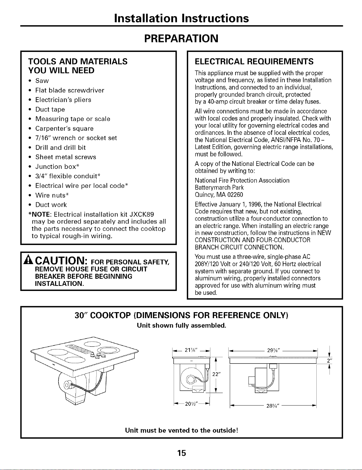
30" COOKTOP (DIMENSIONS FOR REFERENCE ONLY)
Unit shown fully assembled.
21%"
_ 201_2"_
22 tt
T
297/8"
283/4" =
2 H
A
Unit must be vented to the outside!
15
Installation Instructions
CABINET PREPARATION
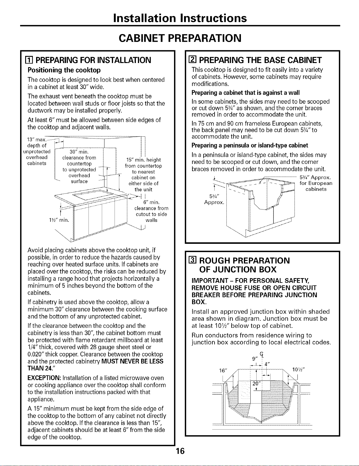
[] PREPARING FOR INSTALLATION
Positioning the cooktop
The cooktop is designed to look best when centered
in a cabinet at least 30" wide.
The exhaust vent beneath the cooktop must be
located between wall studs or floor joists so that the
ductwork may be installed properly.
At least 6" must be allowed between side edges of
the cooktop and adjacent walls.
13" max. _. 4
depth of
unprotected 30" min.
overhead clearance from
cabinets countertop
to unprotected
overhead
surface
11/2"min.
15" min. height
from countertop
to nearest
cabinet on
either side of
the unit
J
6" min.
clearance from
cutout to side
walls
Avoid placing cabinets above the cooktop unit, if
possible, in order to reduce the hazards caused by
reaching over heated surface units. If cabinets are
placed over the cooktop, the risks can be reduced by
installing a range hood that projects horizontally a
minimum of 5 inches beyond the bottom of the
cabinets.
If cabinetry is used above the cooktop, allow a
minimum 30" clearance between the cooking surface
and the bottom of any unprotected cabinet.
If the clearance between the cooktop and the
cabinetry is lessthan 30", the cabinet bottom must
be protected with flame retardant millboard at least
1/4" thick, covered with 28 gauge sheet steel or
0.020" thick copper. Clearance between the cooktop
and the protected cabinetry MUST NEVER BE LESS
THAN 24."
EXCEPTION: Installation of a listed microwave oven
or cooking appliance over the cooktop shall conform
to the installation instructions packed with that
appliance.
A 15" minimum must be kept from the side edge of
the cooktop to the bottom of any cabinet not directly
above the cooktop. If the clearance is less than 15",
adjacent cabinets should be at least 6" from the side
edge of the cooktop.
6
[] PREPARING THE BASE CABINET
This cooktop is designed to fit easily into a variety
of cabinets. However, some cabinets may require
modifications.
Preparing a cabinet that isagainst a wall
In some cabinets, the sides may need to be scooped
or cut down 5_" as shown, and the corner braces
removed in order to accommodate the unit.
In 75 cm and 90 cm frameless European cabinets,
the back panel may need to be cut down 5¾"to
accommodate the unit.
Preparing a peninsula or island-type cabinet
In a peninsula or island-type cabinet, the sides may
need to be scooped or cut down, and the corner
braces removed in order to accommodate the unit.
Approx.
53/4"Approx.
for European
cabinets
[] ROUGH PREPARATION
OF JUNCTION BOX
IMPORTANT - FOR PERSONAL SAFETY,
REMOVE HOUSE FUSE OR OPEN CIRCUIT
BREAKER BEFORE PREPARING JUNCTION
BOX.
Install an approved junction box within shaded
area shown in diagram. Junction box must be
at least 101/2"below top of cabinet.
Run conductors from residence wiring to
junction box according to local electrical codes.
Installation Instructions
CABINET PREPARATION CUTOUTS
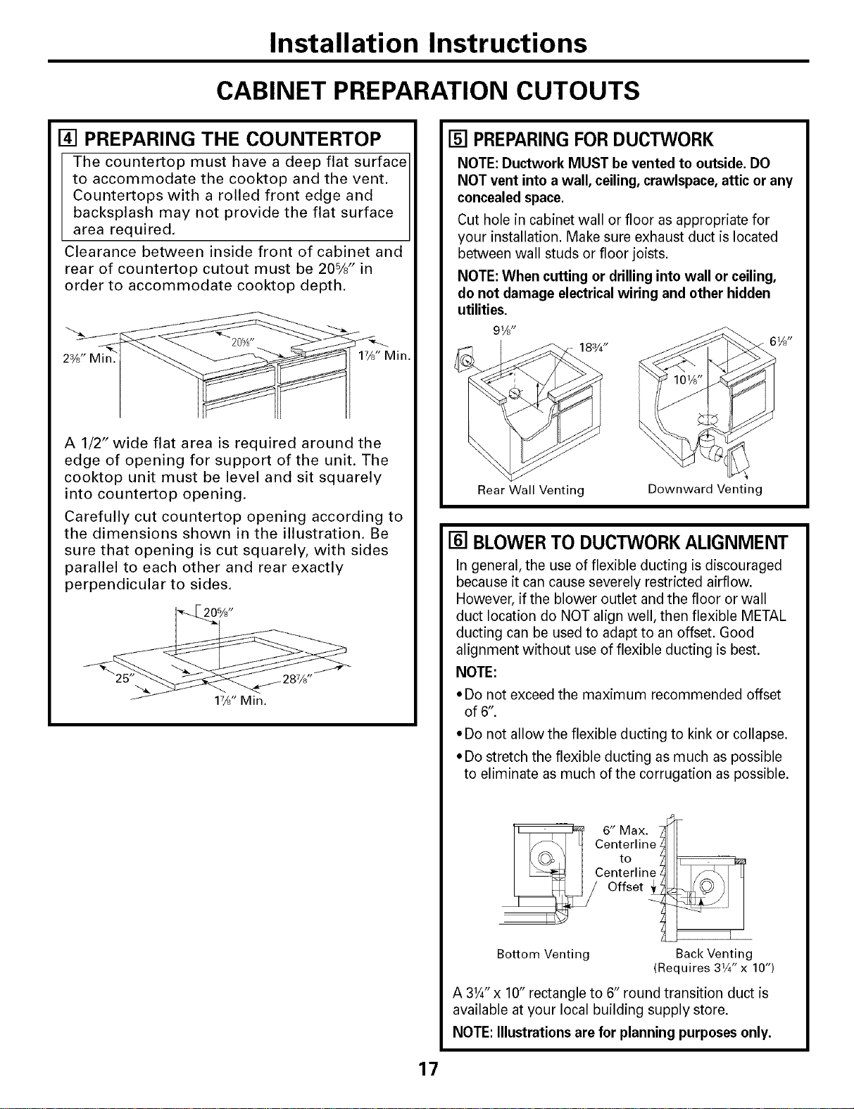
[] PREPARING THE COUNTERTOP
The countertop must have a deep flat surface
to accommodate the cooktop and the vent.
Countertops with a rolled front edge and
backsplash may not provide the flat surface
area required.
Clearance between inside front of cabinet and
rear of countertop cutout must be 20%" in
order to accommodate cooktop depth.
2%" Min. 1%" Min.
A 1/2" wide flat area is required around the
edge of opening for support of the unit. The
cooktop unit must be level and sit squarely
into countertop opening.
Carefully cut countertop opening according to
the dimensions shown in the illustration. Be
sure that opening is cut squarely, with sides
parallel to each other and rear exactly
perpendicular to sides.
20%"
17_" Min.
[] PREPARINGFORDUCTWORK
NOTE: Ductwork MUST be vented to outside. DO
NOT vent into a wall, ceiling, crawlspace, attic or any
concealed space.
Cut hole in cabinet wall or floor as appropriate for
your installation. Make sure exhaust duct is located
between wall studs or floor joists.
NOTE: When cutting or drilling into wall or ceiling,
do not damage electrical wiring and other hidden
utilities.
91/3"
183/4"
Rear Wall Venting
Downward Venting
[] BLOWER TO DUCTWORK ALIGNMENT
In general, the use of flexible ducting is discouraged
because it can cause severely restricted airflow.
However, if the blower outlet and the floor or wall
duct location do NOT align well, then flexible METAL
ducting can be used to adapt to an offset. Good
alignment without use of flexible ducting is best.
NOTE:
• Do not exceed the maximum recommended offset
of 6".
* Do not allow the flexible ducting to kink or collapse.
* Do stretch the flexible ducting as much as possible
to eliminate as much of the corrugation as possible.
_6"Max._ i
Centtejline_ I
Ce_F:_it e t
Bottom Venting Back Venting
(Requires 31¼" x 10")
A 31A'x 10" rectangle to 6" round transition duct is
available at your local building supply store.
NOTE: Illustrations are for planning purposes only.
17
Installation Instructions
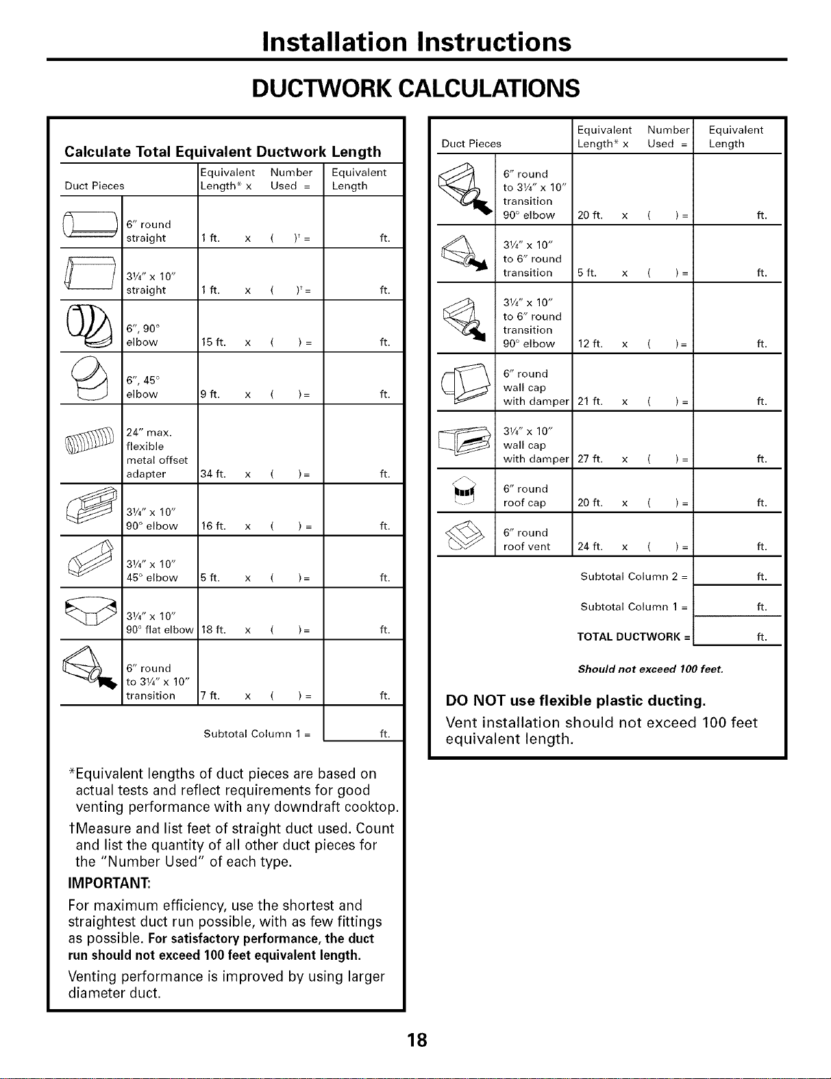
DUCTWORK CALCULATIONS
Calculate Total E(
Duct Pieces
6" round
straight
31/4"x 10"
straight
C_ 6", 90°
elbow
6", 45°
elbow
24" max.
flexible
metal offset
adapter
31/4,,X10, "
90° elbow
31/4" X 10"
45° elbow
31/4,,X10, "
90° flat elbow
6" round
to 31/4" x 10"
transition
uivalent Ductwork Length
Equivalent Number
Length* x Used =
1ft. x ( )*=
1ft. x ( F=
15 ft. x ( ) =
9ft. x ( )=
34 ft. x ( )=
16 ft. x ( ) =
5ft. x ( )=
18 ft. x ( )=
7ft. x ( )=
Subtotal Column 1 =
Equivalent
Length
ft.
ft.
ft.
ft.
ft.
ft.
ft.
ft.
ft.
ft.
*Equivalent lengths of duct pieces are based on
actual tests and reflect requirements for good
venting performance with any downdraft cooktop.
tMeasure and list feet of straight duct used. Count
and list the quantity of all other duct pieces for
the "Number Used" of each type.
IMPORTANT:
For maximum efficiency, use the shortest and
straightest duct run possible, with as few fittings
as possible. For satisfactory performance, the duct
run should not exceed 100 feet equivalent length.
Venting performance is improved by using larger
diameter duct.
Equivalent Number Equivalent
Duct Pieces Length* x Used = Length
6" round
to 31/4" x 10"
transition
90° elbow 20 ft. x ( ) = ft.
31/4"x 10"
to 6" round
transition 5 ft. x ( ) = ft.
[_ 31/4" X 10"
to 6" round
transition
90° elbow 12 ft. x ( )= ft.
6" round
wall cap
with damper 21 ft. x ( ) = ft.
31/4" X 10"wall cap
with damper 27 ft. x ( ) = ft.
6" round
roof cap 20 ft. x ( ) = ft.
6" round
roof vent
24 ft. x ( ) =
Subtotal Column 2 =
Subtotal Column 1 =
TOTAL DUCTWORK =
ft,
ft.
ft.
ft.
Should not exceed 100 feet,
DO NOT use flexible plastic ducting.
Vent installation should not exceed 100 feet
equivalent length.
18
Installation Instructions
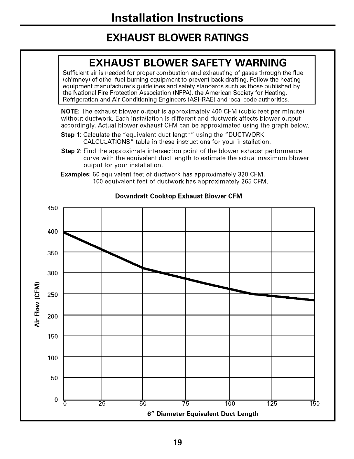
EXHAUST BLOWER RATINGS
45O
EXHAUST BLOWER SAFETY WARNING
Sufficient air is needed for proper combustion and exhausting of gases through the flue
(chimney) of other fuel burning equipment to prevent back drafting. Follow the heating
equipment manufacturer's guidelines and safety standards such as those published by
the National Fire Protection Association (NFPA), the American Society for Heating,
Refrigeration and Air Conditioning Engineers (ASHRAE) and local code authorities.
NOTE: The exhaust blower output is approximately 400 CFM (cubic feet per minute)
without ductwork. Each installation is different and ductwork affects blower output
accordingly. Actual blower exhaust CFM can be approximated using the graph below.
Step 1: Calculate the "equivalent duct length" using the "DUCTWORK
CALCULATIONS" table in these instructions for your installation.
Step 2: Find the approximate intersection point of the blower exhaust performance
curve with the equivalent duct length to estimate the actual maximum blower
output for your installation.
Examples: 50 equivalent feet of ductwork has approximately 320 CFM.
100 equivalent feet of ductwork has approximately 265 CFM.
Downdraft Cooktop Exhaust Blower CFM
g.
O
g.
,m
<[
350
300
25O
200
150
100
50
25 50 75 100 125
6" Diameter Equivalent Duct Length
150
19
Installation Instructions
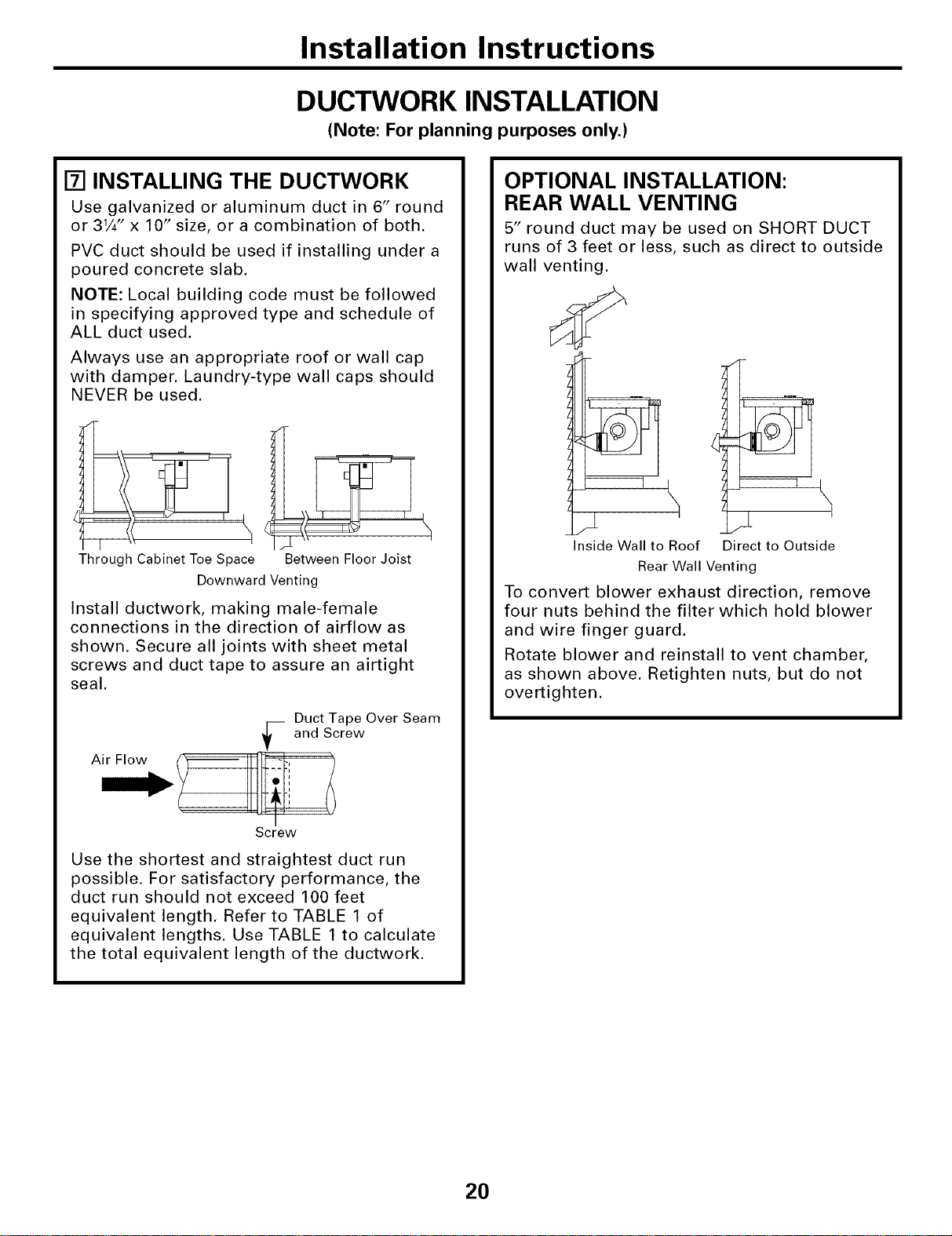
DUCTWORK INSTALLATION
(Note: For planning purposes only.)
[] INSTALLING THE DUCTWORK
Use galvanized or aluminum duct in 6" round
or 31/4" x 10" size, or a combination of both.
PVC duct should be used if installing under a
poured concrete slab.
NOTE: Local building code must be followed
in specifying approved type and schedule of
ALL duct used.
Always use an appropriate roof or wall cap
with damper. Laundry-type wall caps should
NEVER be used.
Through Cabinet Toe Space
Between Floor Joist
Downward Venting
Install ductwork, making male-female
connections in the direction of airflow as
shown. Secure all joints with sheet metal
screws and duct tape to assure an airtight
seal.
Duct Tape Over Seam
-- and Screw
Screw
Use the shortest and straightest duct run
possible. For satisfactory performance, the
duct run should not exceed 100 feet
equivalent length. Refer to TABLE 1 of
equivalent lengths. Use TABLE 1 to calculate
the total equivalent length of the ductwork.
OPTIONAL INSTALLATION:
REAR WALL VENTING
5" round duct may be used on SHORT DUCT
runs of 3 feet or less, such as direct to outside
wall venting.
Inside Wall to Roof Direct to Outside
Rear Wall Venting
To convert blower exhaust direction, remove
four nuts behind the filter which hold blower
and wire finger guard.
Rotate blower and reinstall to vent chamber,
as shown above. Retighten nuts, but do not
overtighten.
20
Installation Instructions
UNPACKING THE COOKTOP/INSTALLING THE GASKET
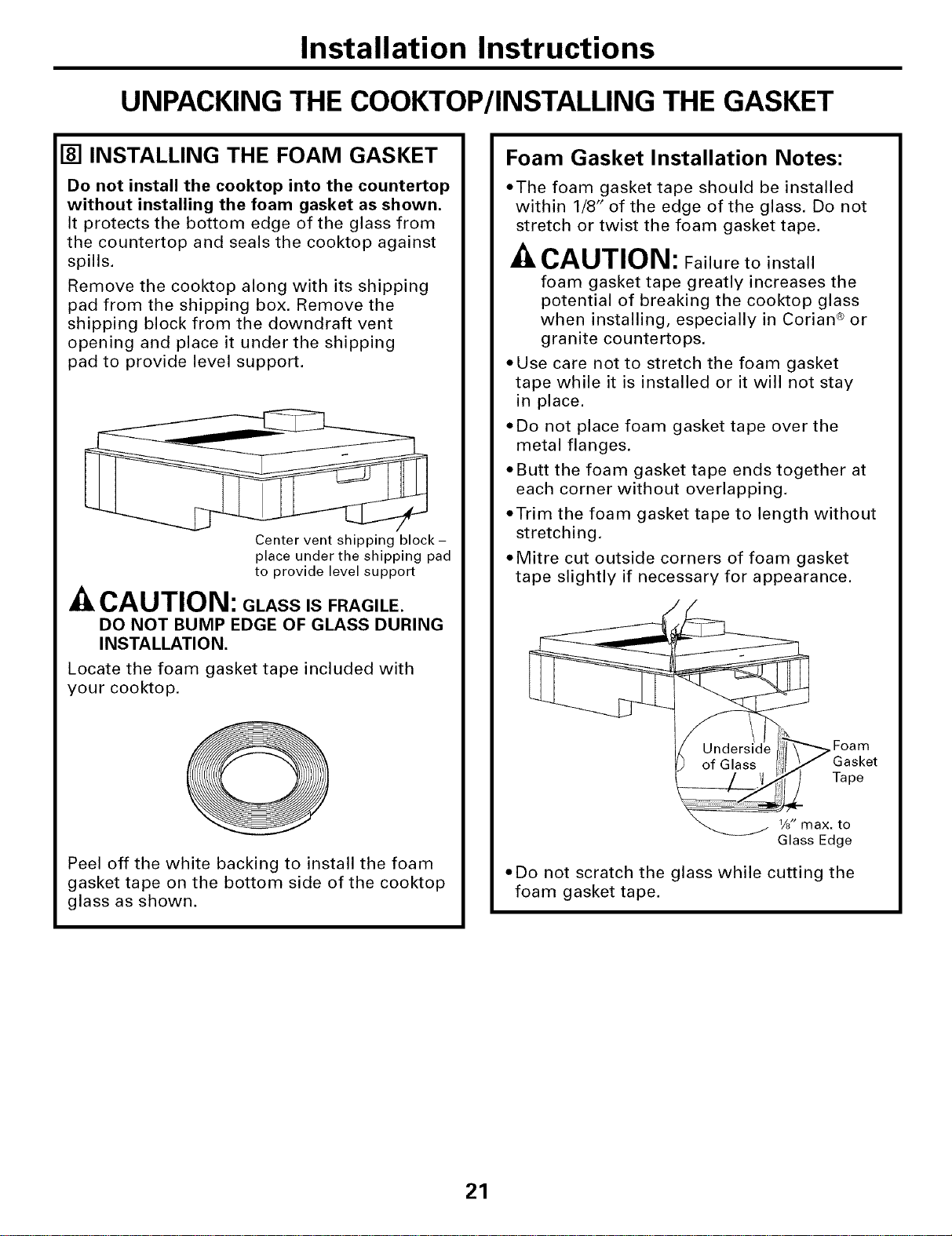
[] INSTALLING THE FOAM GASKET
Do not install the cooktop into the countertop
without installing the foam gasket as shown,
It protects the bottom edge of the glass from
the countertop and seals the cooktop against
spills.
Remove the cooktop along with its shipping
pad from the shipping box. Remove the
shipping block from the downdraft vent
opening and place it under the shipping
pad to provide level support.
Center vent shipping block -
place under the shipping pad
to provide level support
CAUTION: GLASS IS FRAGILE.
DO NOT BUMP EDGE OF GLASS DURING
INSTALLATION.
Locate the foam gasket tape included with
your cooktop.
Peel off the white backing to install the foam
gasket tape on the bottom side of the cooktop
glass as shown.
Foam Gasket Installation Notes:
• The foam gasket tape should be installed
within 1/8" of the edge of the glass. Do not
stretch or twist the foam gasket tape.
CAUTION: Failure to install
foam gasket tape greatly increases the
potential of breaking the cooktop glass
when installing, especially in Corian ® or
granite countertops.
• Use care not to stretch the foam gasket
tape while it is installed or it will not stay
in place.
• Do not place foam gasket tape over the
metal flanges.
• Butt the foam gasket tape ends together at
each corner without overlapping,
• Trim the foam gasket tape to length without
stretching.
• Mitre cut outside corners of foam gasket
tape slightly if necessary for appearance.
. Gasket
ax. to
Glass Edge
• Do not scratch the glass while cutting the
foam gasket tape.
21
Installation Instructions
INSTALLING THE COOKTOP
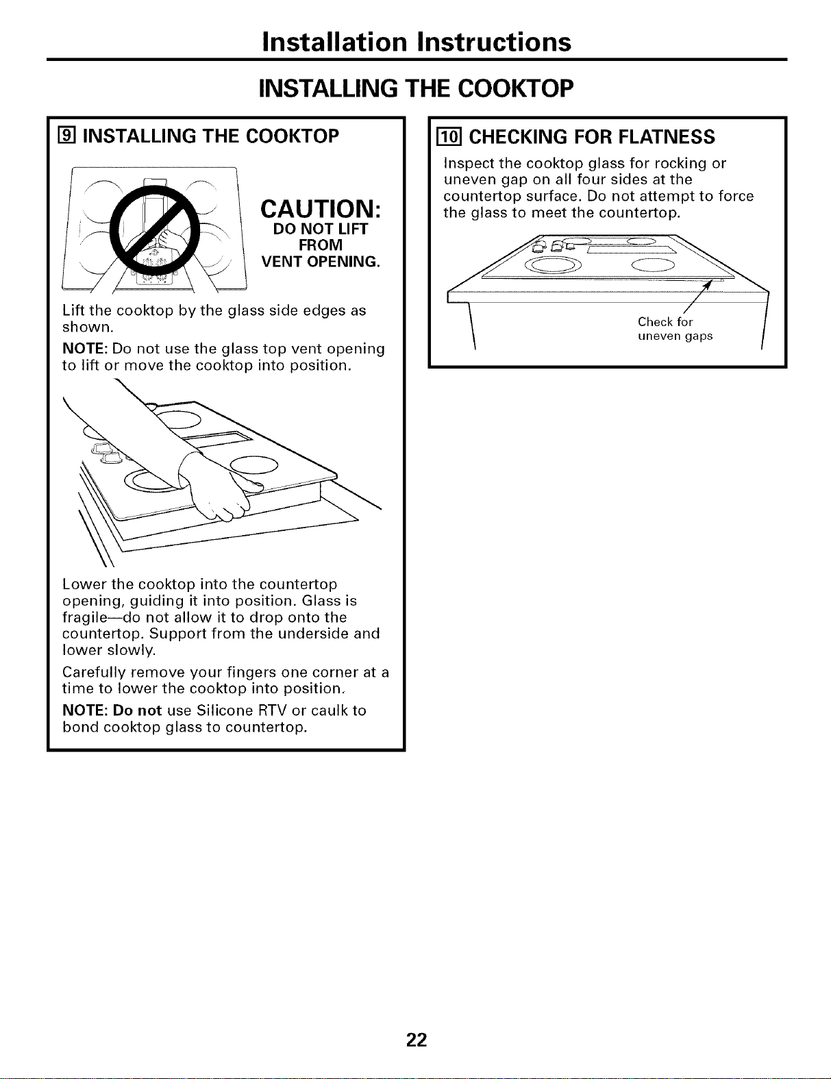
[] INSTALLING THE COOKTOP
CAUTION:
DO NOT LIFT
FROM
VENT OPENING.
Lift the cooktop by the glass side edges as
shown.
NOTE: Do not use the glass top vent opening
to lift or move the cooktop into position,
Lower the cooktop into the countertop
opening, guiding it into position. Glass is
fragileido not allow it to drop onto the
countertop. Support from the underside and
lower slowly.
Carefully remove your fingers one corner at a
time to lower the cooktop into position,
NOTE: Do not use Silicone RTV or caulk to
bond cooktop glass to countertop.
[] CHECKING FOR FLATNESS
Inspect the cooktop glass for rocking or
uneven gap on all four sides at the
countertop surface. Do not attempt to force
the glass to meet the countertop.
Check for
uneven gaps
22
Installation Instructions
INSTALLING THE COOKTOP
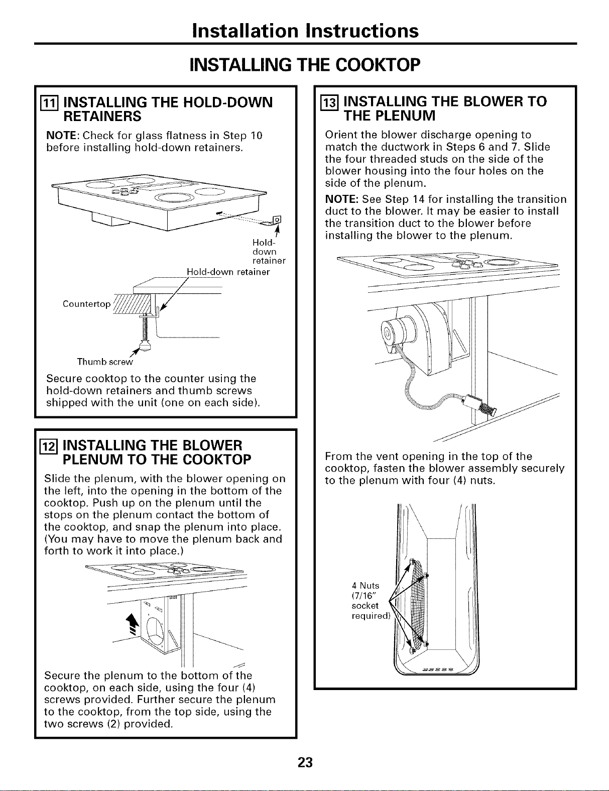
[] INSTALLING THE HOLD-DOWN
RETAINERS
NOTE: Check for glass flatness in Step 10
before installing hold-down retainers.
Hold-
down
retainer
Hold-down retainer
Countertop _
Thumb screw
Secure cooktop to the counter using the
hold-down retainers and thumb screws
shipped with the unit (one on each side).
I-_ INSTALLING THE BLOWER
PLENUM TO THE COOKTOP
Slide the plenum, with the blower opening on
the left, into the opening in the bottom of the
cooktop. Push up on the plenum until the
stops on the plenum contact the bottom of
the cooktop, and snap the plenum into place.
(You may have to move the plenum back and
forth to work it into place.)
Secure the plenum to the bottom of the
cooktop, on each side, using the four (4)
screws provided. Further secure the plenum
to the cooktop, from the top side, using the
two screws (2) provided.
[_ INSTALLING THE BLOWER TO
THE PLENUM
Orient the blower discharge opening to
match the ductwork in Steps 6 and 7. Slide
the four threaded studs on the side of the
blower housing into the four holes on the
side of the plenum.
NOTE: See Step 14 for installing the transition
duct to the blower. It may be easier to install
the transition duct to the blower before
installing the blower to the plenum.
From the vent opening in the top of the
cooktop, fasten the blower assembly securely
to the plenum with four (4) nuts.
4 Nuts
(7/16"
socket
23
Installation Instructions
INSTALLING THE COOKTOP
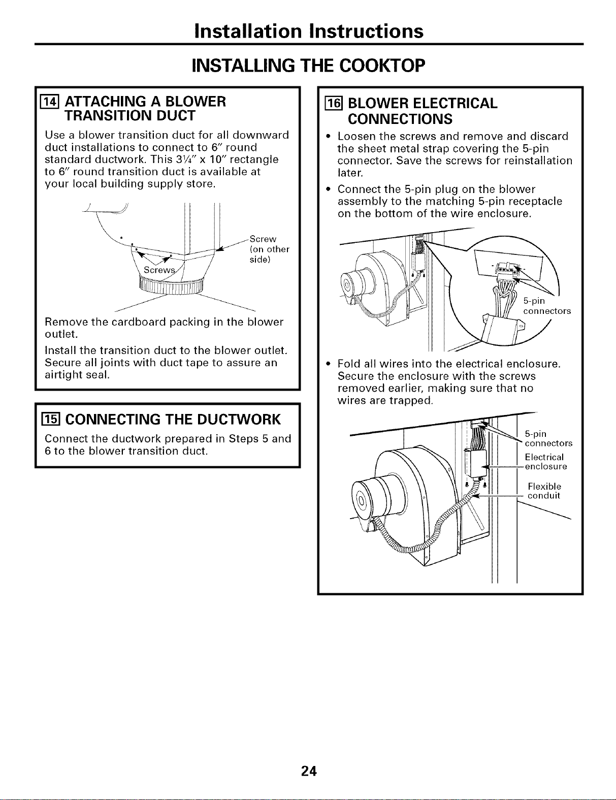
[] ATTACHING A BLOWER
TRANSITION DUCT
Use a blower transition duct for all downward
duct installations to connect to 6" round
standard ductwork. This 31/4" x 10" rectangle
to 6" round transition duct is available at
your local building supply store.
Screw
(sl°_e_ther
Remove the cardboard packing in the blower
outlet.
Install the transition duct to the blower outlet.
Secure all joints with duct tape to assure an
airtight seal.
CONNECTING THE DUCTWORK
Connect the ductwork prepared in Steps 5 and
6 to the blower transition duct.
[_] BLOWER ELECTRICAL
CONNECTIONS
* Loosen the screws and remove and discard
the sheet metal strap covering the 5-pin
connector. Save the screws for reinstallation
later.
• Connect the 5-pin plug on the blower
assembly to the matching 5-pin receptacle
on the bottom of the wire enclosure,
5-pin
connectors
Fold all wires into the electrical enclosure.
Secure the enclosure with the screws
removed earlier, making sure that no
wires are trapped.
S-pin
connectors
Electrical
-- -enclosure
Flexible
conduit
24
Installation Instructions
ELECTRICAL CONNECTIONS
[] BEFORE MAKING ELECTRICAL
CONNECTIONS
Note to Electrician: The power leads supplied
with this appliance are UL-recognized for
connection to large gauge household wiring.
The insulation of these leads is rated
at temperatures much higher than the
temperature rating of household wiring.
The current carrying capacity of a conductor is
governed by the wire gauge and also the
temperature rating of the insulation around the
wire.
Aluminum Wiring -WARNING: IMPROPER
CONNECTION OF ALUMINUM HOUSE WIRING
TO THE COPPER LEADS CAN RESULT IN
SERIOUS PROBLEMS.
Attach copper wires to aluminum wiring using
special connectors designed and
UL-listed for joining copper to aluminum. Follow
the connector manufacturer's recommended
procedure closely.
Service Loop - Leave a loop in the wires to the
cooktop so that the cooktop can be lifted 12
inches without having to disconnect the wiring.
ELECTRICAL REQUIREMENTS*
Model # Voltage Frequency KW
JP989 120/240V 60Hz 8.8KW
120/208V 60Hz 6.7KW
*For reference only. Verify with product rating
plate.
[] INSTALL 3/4" FLEXIBLE CONDUIT
Remove the screws holding
the wire compartment cover
and remove the cover.
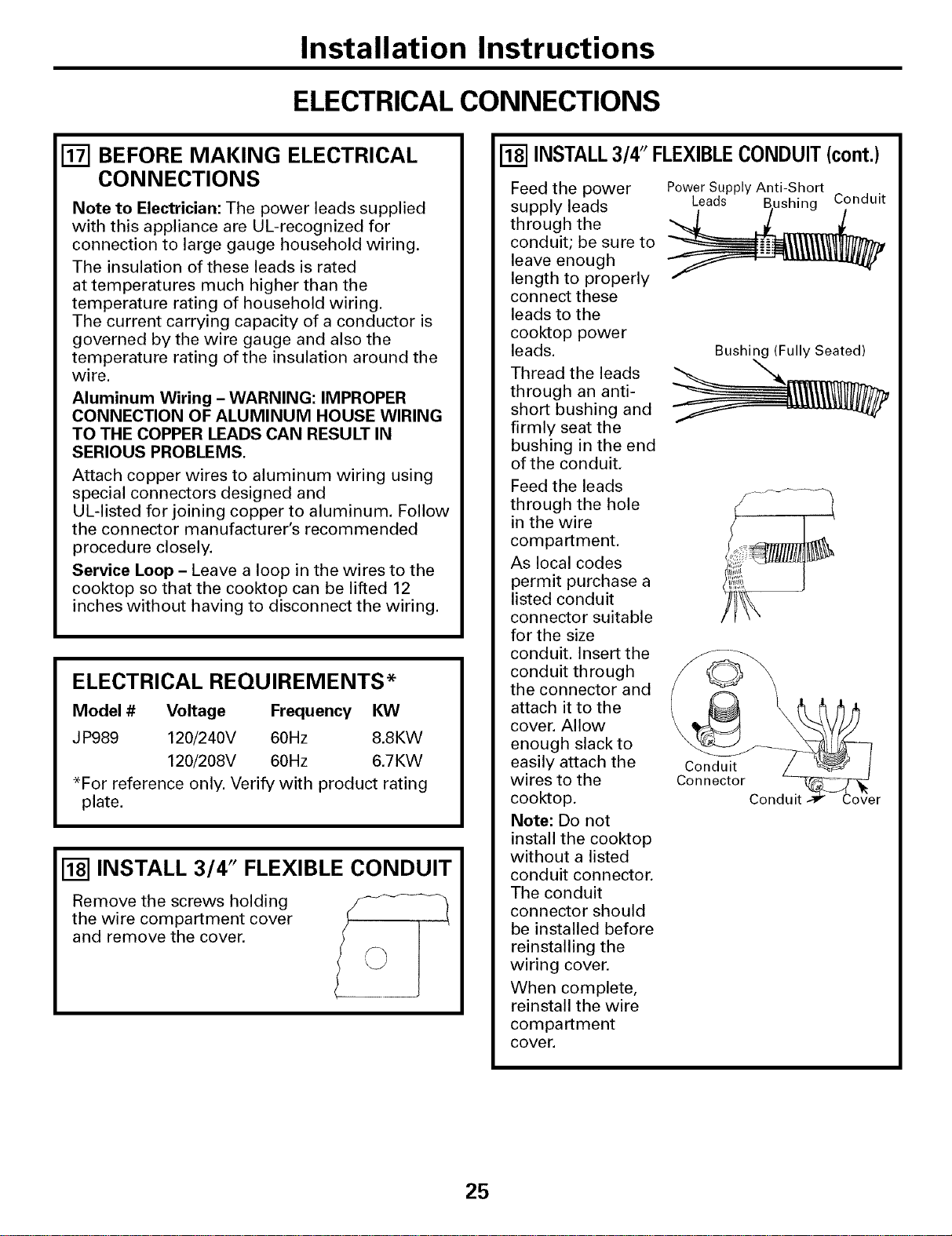
INSTALL3/4" FLEXIBLECONDUIT(cont.)
Feed the power
supply leads
through the
conduit; be sure to
leave enough
length to properly
connect these
leads to the
cooktop power
leads.
Thread the leads
through an anti-
short bushing and
firmly seat the
bushing in the end
of the conduit,
Feed the leads
through the hole
in the wire
compartment,
As local codes
permit purchase a
listed conduit
connector suitable
for the size
conduit. Insert the
conduit through
the connector and
attach it to the
cover. Allow
enough slack to
easily attach the
wires to the
cooktop.
Note: Do not
install the cooktop
without a listed
conduit connector.
The conduit
connector should
be installed before
reinstalling the
wiring cover.
When complete,
reinstall the wire
compartment
cover.
Power Supply Anti-Short
Leads ushing Conduit
Bushing (Fully Seated)
Conduit
Connector
25
Installation Instructions
ELECTRICAL CONNECTIONS
MAKING ELECTRICAL
CONNECTIONS
Effective January 1, 1996, the National
Electrical Code requires that new, but not
existing, construction utilize a four-conductor
connection to an electric range. When
installing an electric range in new
construction, follow the instructions in NEW
CONSTRUCTION AND FOUR-CONDUCTOR
BRANCH CIRCUIT CONNECTION.
You must use a three-wire, single-phase
AC 208Y/120 Volt or 240/120 Volt, 60 Hertz
electrical system with separate ground.
If you connect to aluminum wiring, properly
installed connectors approved for use with
aluminum wiring must be used.
New construction and four-conductor branch
circuit connection
• When installing in new construction, or
• When installing in a mobile home, or
• When local codes do not permit grounding
through neutral:
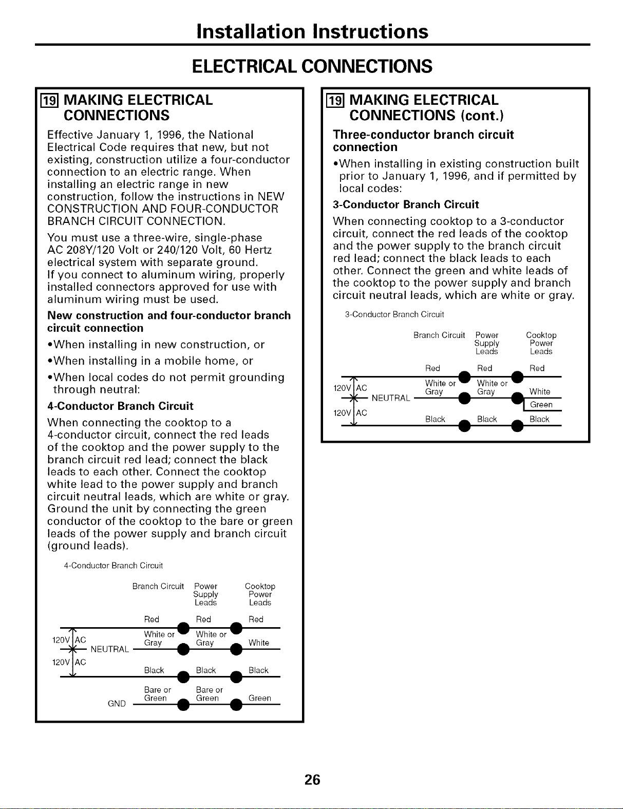
4-Conductor Branch Circuit
When connecting the cooktop to a
4-conductor circuit, connect the red leads
of the cooktop and the power supply to the
branch circuit red lead; connect the black
leads to each other. Connect the cooktop
white lead to the power supply and branch
circuit neutral leads, which are white or gray.
Ground the unit by connecting the green
conductor of the cooktop to the bare or green
leads of the power supply and branch circuit
(ground leads).
4-Conductor Branch Circuit
120VIAC
Branch Circuit Power
Supply
Leads
Cooktop
Power
Leads
NEUTRAL
Red
White or W
Gray _,
Red Red
White or lw
Gray rib, White
GND
Black db, Black ,_. Black
Bare or Bare or
Green ._ Green dlh Green
MAKING ELECTRICAL
CONNECTIONS (cont.)
Three-conductor branch circuit
connection
• When installing in existing construction built
prior to January 1, 1996, and if permitted by
local codes:
3-Conductor Branch Circuit
When connecting cooktop to a 3-conductor
circuit, connect the red leads of the cooktop
and the power supply to the branch circuit
red lead; connect the black leads to each
other. Connect the green and white leads of
the cooktop to the power supply and branch
circuit neutral leads, which are white or gray.
3-Conductor Branch Circuit
120VIAC
Branch Circuit Power Cooktop
Supply Power
Leads Leads
NEUTRAL
Red _,. Red ,._ Red
White or IP' White or I_'
Gray rib, Gray A White
I1, Green
Black _b, Black A Black
26
Installation Instructions
FINAL ASSEMBLY
[] INSTALL DOWNDRAFT FILTER
AND VENT GRILLE
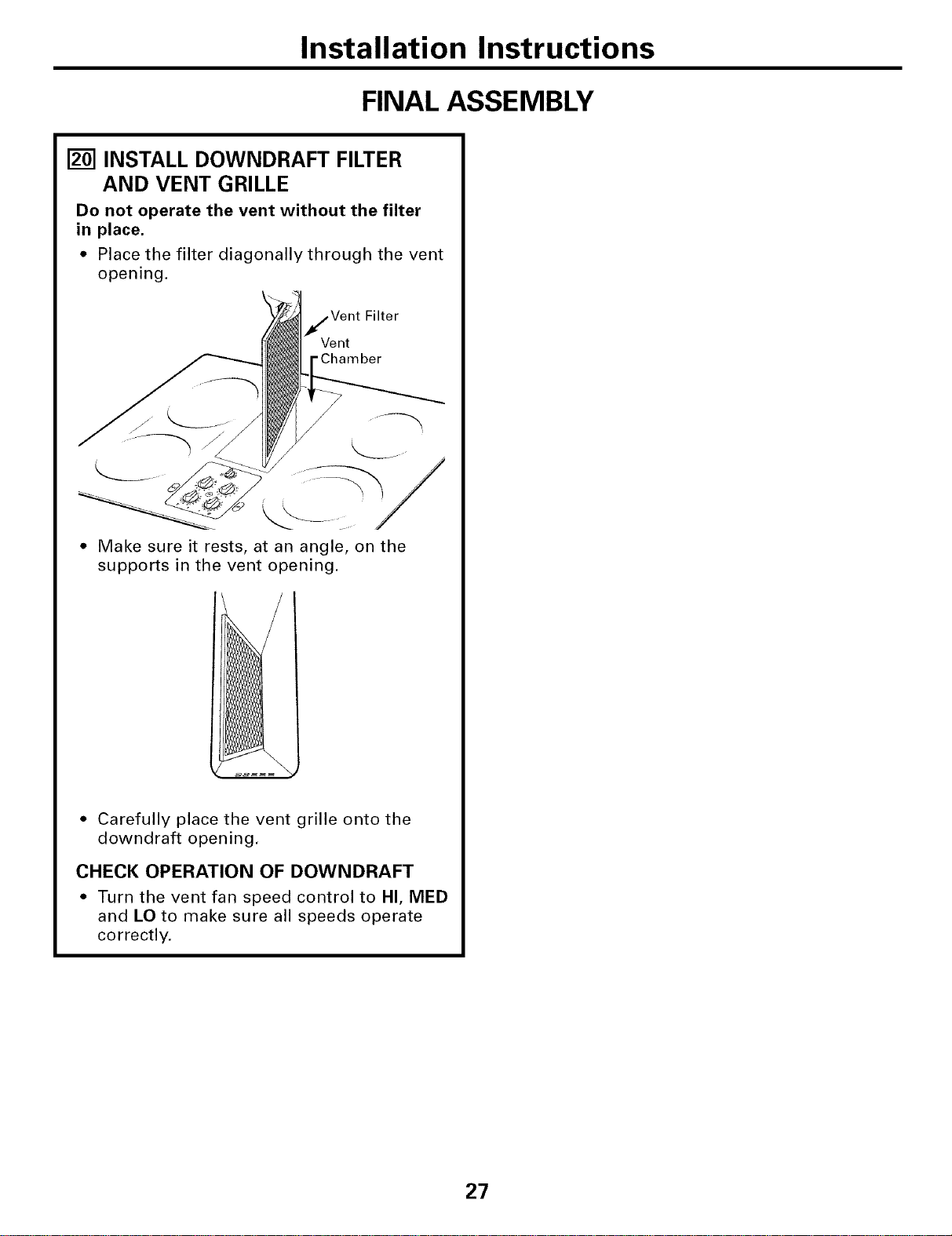
Do not operate the vent without the filter
in place.
• Place the filter diagonally through the vent
opening.
Filter
Vent
"Chamber
• Make sure it rests, at an angle, on the
supports in the vent opening.
• Carefully place the vent grille onto the
downdraft opening.
CHECK OPERATION OF DOWNDRAFT
• Turn the vent fan speed control to HI, MED
and LO to make sure all speeds operate
correctly.
27
Beforeyoucall forservice...
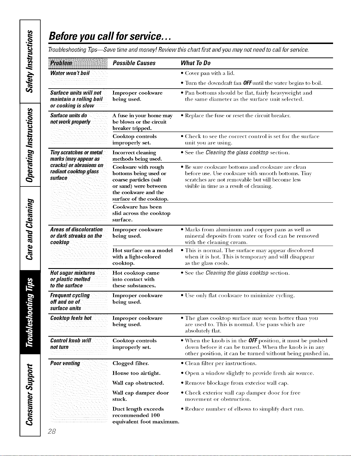
Troubleshooting -tips--Save time and money/. Review this chart first and you may not need to call for service.
Possible Causes
Water won't boil
What ToDo
• Co_er pan with a lid.
• Turn the downdrafl tim OFFuntil the water begins to boil.
Surface units will not Improper cookware • Pan bottolns should be flat, tairly heavyweight and
maintaina rollingboil being used. the salne dialneter as the surthce unit selected.
or cookingis slow
Surface units do A fuse ha your home may * Replace the tuse or reset the circuit breakei;
not work properly be blown or the circttit
breaker tripped.
Cooktop controls * Check to see the correct control is set for the surtace
improperly set. unit 3ou are using.
Tinyscratches ormetal Incorrect cleaning * See the Cleaning theglass cooktop section.
marks (may appear as methods being used.
cracks) orabrasions on Cookwa_e with rough
radiant coolaop glass bottoms being used or
surface com'se pm'ticles (salt
or staid) were between
the cookwaxe and the
surface of the cooktop.
Cookwaxe has been
slid across the cooktop
surface.
• Be StlYe co(tkware bottolns and cookware aI'e clean
before use. Use cookware with smooth bottoms. Tinv
scratches are not iemox_d)le but will become less
visible in time as a result of cleaning.
Areas ofdiscoloration Improper cookware • Marks fr(nn almninum and copper pans as well as
or dark streaks on the being used, mineral del)osits from water or food can be removed
cooktop with the cleaning cream.
Hot surface on a model • This is noruml. The surtace may al)l)ear discoh)red
with a light-colored when it is hot. This is teml)orary and will disal)l)ear
cooktop, as the glass cools.
Hot sugar mixtures Hot cooktop came • See the Cleaningthe glass cooktop section.
or plasticmelted into contact with
to the surface these substances.
Frequent cycling Improper cookware • Use only flat cookware to minimize cvclin
off and on of being used.
surface units
Cooktop feels hot Improper cookware • Tile glass cooktop surtace may seem hotter than you
being used. are used to. This is n(mnal. Use pans which are
absolutely flat.
Control knob will Cooktop controls • When the knob is in the OFF position, it lnust be pushed
not turn improperly set. down before it can be turned. \,Vhen the knob is in any
other l)osition, it can be turned without bein,_ l)ushed in.
Poorventing Clogged filter. • (]lean filter l)er instructions.
House too airtight. • Open a window slightly to l)rovide fresh air sot/rce.
Wall cap obstructed, • Remove bh)ckage froul exterior wall cap.
Wall cap damper door • Check exterior wall cap dmnl)er door for free
stuck, l/lOVell/en[ or obstrt/ction.
Duct length exceeds • Reduce imlnber of elbows to silnplit}' duct lUlL
recommended 100
equivalent foot maximum.
28
GE Service Protection Plus rM
GE, a name recognized worldwide _br quality and dependability; oflers y'ou
Service Protection Plus'"--comprehensive protection on all y'our appliances--
No Matter What Brand!
Benefits Include:
• Backed by GE
• All brands covered
• Unlimited service cars
• All parts and labor costs included
• No out-of-pocket expenses
• No hidden deductibles
• One 800 number to call
We71CoverAnyAppliance.
Anywhere. Anytime.*
You will be c()mpletel,_ satisfied with our serxice protection or you may request }our inonev back
on tile remaining xalue of _o/u" contract. No questions asked. It's that simple.
Protect vom" refl_igerat(m dishwasher; washer and (hTe_; range, TV, VCR and much more--any brmad!
Plus there's iso extra charge tot eulergency ser;'ice and low monthly financing is available. Even icemaker
coverage and tood spoilage protection is offered. You can rest eas> knowing that all vom" valuable
household products are protected against expensive repairs.
Place your confidence in (;E and call us in tile Ij.S. toll-free at _tlU._)Z_).ZZZ/-]:
for inoi'e infoi'u/ation,
*-M1lmmds cov<_<d, up Io 20 ?'<a_ old, in Ih< <onlinental U.S.
__ _C/_ll'h__2e............
Please place in envelope and mail to:
General Electric Company
Warranty Registration Department
EO. Box 32150
Louisville, KY 40232-2150
29
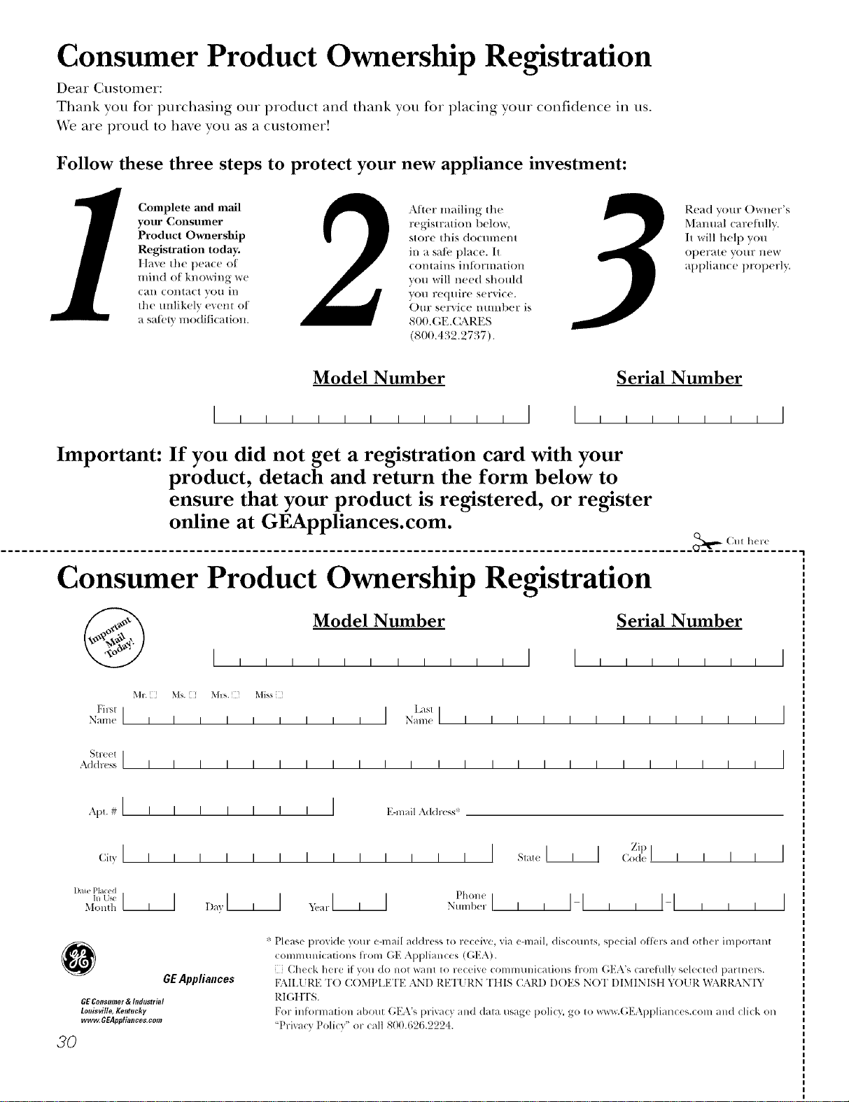
Consumer Product Ownership Registration
Dear Customer:
Thank you for purchasing our product and thank you for placing your confidence in us.
_A/eare proud to ha_e you as a customer!
Follow these three steps to protect your new appliance investment:
Complete mid mail
your Consumer
Product Ownership
Registration today.
Ilave the peace of
mind of knowing we
can contact you ill
the mflikely (veto of
a satetv modification.
After mailing {lie
regis{ration below,
store tiffs docmnem
in a sa/;v place. It
contaills inl{)rli]atioll
you will need should
vou req/lire service.
Ore" service mmd)er is
800.GE.(L_\ RFS
(800.432.2737).
Read Vo/Ir Owner's
Mmmal careflfllv.
I{ will help you
ot)erate yo/lr l](W
at)t)liance t)rot)erly.
Model Number Serial Number
I I I I I
Important: If you did not get a registration card with your
product, detach and return the form below to
ensure that your product is registered, or register
online at GEAppliances.com.
._,,.- Cm h(r(
Consumer Product Ownership Registration
Model Number Serial Number
I I I
Mr. his. M]s. Mis_
First] [ Lasl[
Nam_ I I I I I I I I I Name I I I I I I I I I I I I
St feet I
Address I I I I I I I I I I I I I I I I I I I I I I I I
, I
I
I
Ap,. # [ [ [ [ [ [ [ [ [ E-mail Ad{h, ss:
Zip [
I I I
GEAppliances
GEConsomor& IndostriM
Louisville,Kentucky
www.GEAppliances.com
20
* Please provide your e-mail ad(tress to receive, xia e-mail, discomlts, special ottbrs and other important
connmnfications fl-om GE Appliances ((;EA).
[ Check here iI vou do not want to receive communications fl-om GEA's careiully selected partners.
FAILI JRE TO (X }MPLETE AN[) RETI JRN TIIIS CARD D()ES NOT DIMINIStt h_)l JR _,\(\RI_\N'[Y
RIGIfFS.
For in{ormation about GEA's privacy and data usage poli{3, go to wx_v.(;EAppliances.com and click on
"Privacy Policy" or call 800.626.2224.
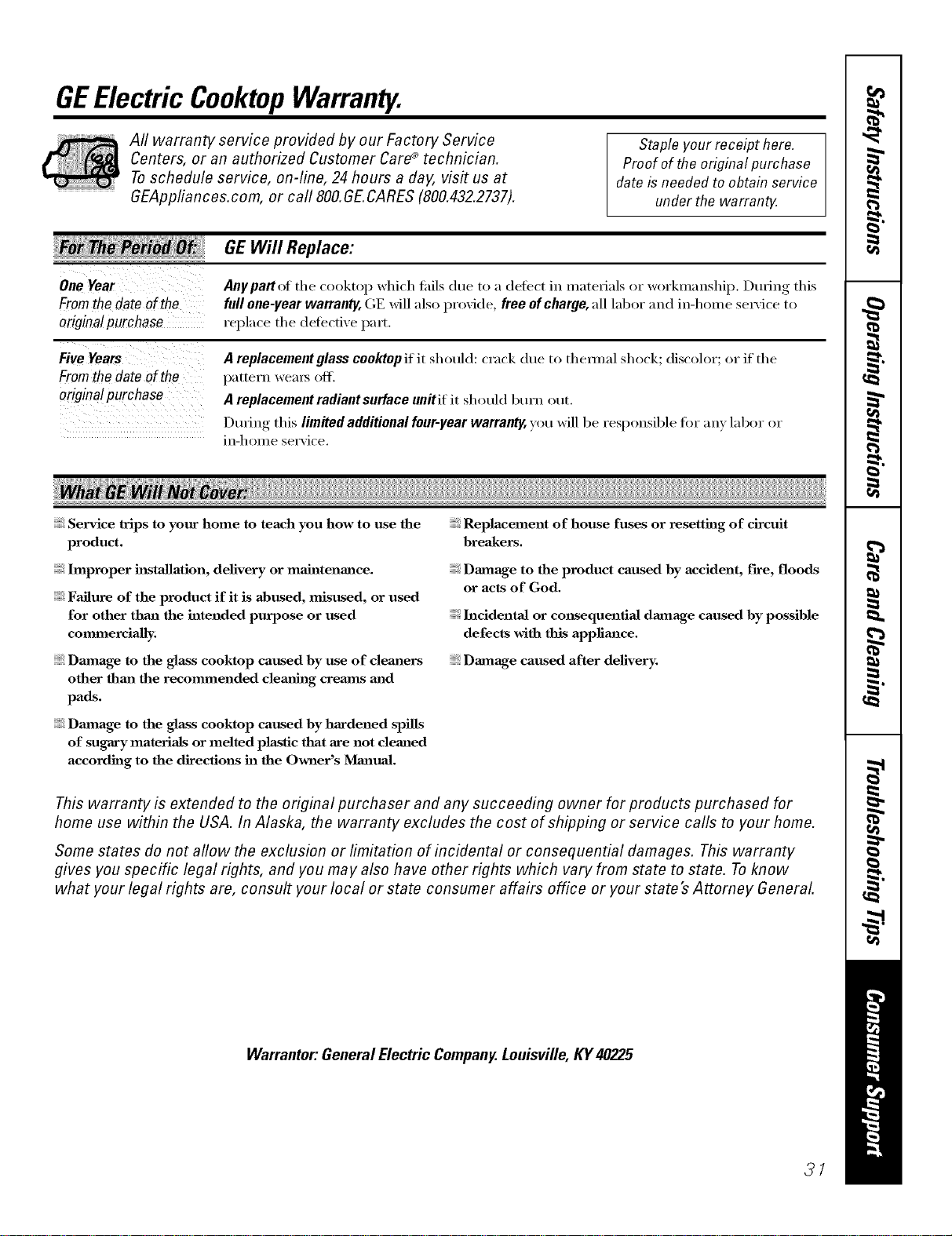
GEElectric CooktopWarranty.
Aft warranty service provided by our Factory Service
Centers, or an authorized Customer Care®technician.
Toschedule service, on-line, 24 hours a day, visit us at
GEAppfiances.com, or call 800.GE.CARES (800.432.2737).
Staple your receipt here.
Proof of the original purchase
date is needed to obtain service
under the warran_
From the date of the
origina! purchase
GEWill Replace:
Aaypattof the cooktop which tifils due to a defect in materials or workmanship, t)udng this
full one-year warranty, GE will also provkle, free of charge, all labor and in-home sex_'ice to
replace the defective part.
Fromthe dateof the
origina/purchase
A replacement glass cooktop if it should: crack due to them/al shock; discolor; or if the
pattern weai_ oit_
A replacement radiant surface unitif it should burn out.
L)udng this lim#ed additional four-year warranty, you will be responsible for any labor or
in-home service.
Service trips to your home to teach you how to use the
product.
hnproper installation, delivery or maintenance.
Failure of the product if it is abused, misused, or used
for other thml the intended purpose or used
commercially.
Dmnage to the glass cooktop caused hy use of cleaners
other than the recommended clem_hlg cretans and
pads.
Dmnage to the glass cooktop caused by hardened spills
of sugary materials or melted plastic that are not cleaned
accordh_g to the directions in the Owner's Manual.
Replacement of house fuses or resetting of circuit
breakers.
Damage to the product caused by accident, f'we, floods
or acts of God.
hlcidentaJ or consequential damage caused by possible
defects with this appliance.
Damage caused after delivery.
This warranty is extended to the original purchaser and any succeeding owner for products purchased for
home use within the USA. In Alaska, the warranty excludes the cost of shipping or service calls to your home.
Some states do not allow the exclusion or limitation of incidental or consequential damages. This warranty
gives you specific legal rights, and you may also have other rights which vary from state to state. Toknow
what your legal rights are, consult your local or state consumer affairs office or your state's Attorney General
Warrantor," General Electric Company.Louisville, KY 40225
31
ConsumerSupport.
gEAppliancesWebsite GEAppliances.com
Have a question or need assistance with your appliance? Try the GE Appliances X.Vebsite 24 hou_ a day,
any day of the year'. For greater convenience and faster service, you can now download Owner's Manuals,
order parts, catalogs, or even schedule service ondine. Y_)u can also "_sk Ore" Team of EN)erts .....
your questions, and so much more...
ScheduleService
GEAppliances.com
Expert (;E repair se_Mce is only one step awa) fl'om your doo_: Get on-line and schedule your service at
( " 1
your con',enience 24 hom_ any day )f the veal Or call 800.GE.(:ARES (800.432.2737) dunng nomml
business hom_.
RealLifeDesignStudio GEAppliances.com
GE supports the Uni\'e_al Design concept--products, services and enviromnents that can be used by
people of all ages, sizes and capabilities. We recognize the need to design tbr a wide range ot physical and
mental abilities and impaim/ents. For details of GE's Univex_al Design applications, including kitchen
design ideas tot people with disabilities, check out our X.Vebsite today: For the hearing impaired, please call
800.TDD.GEAC (800.833.4322).
ExtendedWarranties GEAppliances.com
Pro'chase a GE extended _arrant_ and learn about special discounts that are a_ailable while _our _arrant_
is still in effect. You can purchase it on-line an_ tilne, or call 800.626.2224 during nomml business hom_.
GE Consumer Home Set\ices will still be there after your warran_ expires.
PartsandAccessories GEAppliances.com
Individuals qualified to se_Mce their own appliances can have parts or accessories sent directly to their
homes (VISA, MasterCard and Discover cards are accepted). Order on-line today, 24 hom_ eve_a' day or
by phone at 800.626.2002 during nomml business hom_.
Instructions contained in this manual cover procedures tobeperformed by any user. Other servicing generally
should be referred to qualified service personnel Cautionmust be exercised, since improper servicing may cause
unsafe operation.
ContactUs GEAppliances.com
If you are not satisfied with the service you receive ti'om GE, contact us on our Website with all the details
including your phone numbe_; or write to: General Manage_; Customer Relations
GE Appliances, Appliance Park
I,ouisville, K¥ 40225
Register YourAppliance GEAppliances.com
Register your new applimace on-lhle--at your convenience! Timely product registration will allow for
enhanced communication and prompt service under the temps of _our warrant); should the need arise.
You may also mail in the pre-printed registration card included in the I)ackiw"_ material.
Printed in flTeUnited States
GEAppliances.com
v
°_
Instruc_ones de seguridad ......... 9-5
Instrucz_ones de opera_6n
Caracterfsficas de su estufi_ ............ 6
Ideas sobre las piezas de cocina ........ 9
IJmitador de temperatura ............ 8
Quemador de puente ................ 8
Sistema de ventilaci6n de la estul2a ...... 8
Unidades de superficie ............. 7, 8
Unidad de superficie doble ........... 8
Cuidado y limpieza
gotones de control ................. ] 0
Estufa de vidfio ................. 11, 19
Filuo de ventilaci6n ................. 10
Sismma de x>ntilaci6n ............... 10
Instruc_ones de instala_6n
C6mo desempacar la estul_a ....... 14, 91
C6mo instalar la esmlh ........... 92-24
C6mo instalar lajunta ............... 91
Conexiones el_cuicas ............ 24-26
Ensambladura final ................. 97
Indices de soplado de escape ......... 19
Precauciones de segufidad ........... 13
Pleparaci6n .................... 15-17
Red de conductos ............ 17-90, 94
Ideas sobre la identifica_q6n
y solu_q6nde averias. .............. 98
Apoyo al consumidor
Apoyo al consumidor . .............. 39
Garantfa .......................... 31
Escriba el n#mero de modelo y
de serie aquL"
Modelo #
Serie #
En(tlenti'e estos n(llllei'os en tlll_l
etiqueta debajo de la estulh, en el
lado de la cfmara de ventilaci6n.
JP98 9
49-80283 01-05JR
INSTRUCCIONESDESEGURIDADIMPORTANTES.
LEATODASLASINSTRUCCIONESANTESDEUSAR.
2
PRECAUCIONESDESEGURIDAD
ADVERTENCIA- PARAREDUCIRELRIESGODE
INCENDIOS,DESCARGASEU_'CTRICAS0 LESIONES
PERSONALES,OBSERVELOSIGUIENTE:
A. [lse este mfmual solamente de lamanera que el
fifl)ficantelo indique. Siusted fiene preguntas,
p6ngase en contacto con el fM)ricante.
B. Antes de proporcionar servicioo de limpiar la
unidad, desconecte elstm_inistroel6cuico en el
panel de serviciovcie_Teel mecanismo de seguridad
pare evitarque alguien lo conecte accidentalmente.
Cuando no existaun dispositi\o de ciertv de
segmidad, amarre un avisovisible,como una
etiqueta al panel de serviciohaciendo la advertencia.
C. No use esta unidad con ningtin dispositivode
control de velocidadde estado s61ido.
D. Estaunidad debe estar conectada a derra.
PRECAUClON- Para..o vo.tilaci ,,go.oral
solamente.Nouseparaexpulsarmaterialespeligrososo
explosivosyvapores.
ADVERTENCIA- PARAREDUOIRELRIESGODE
LESIONESPERSONALESENELCASODEUNINCENDIO
DEBIDOAGRASADEESTUFAQUEMADA,HAGALO
SIGUIENTE*:
A. CONTENGAi.kS ig_'Lkq con una tapa que ajuste
Mensobre la sart_n, con una Mmina para hacer
dulces o con una bandeja met_lica,y luego apague el
quemador TENGACUIDADODENO QUEMARSE.
Silasllamasno se apagTminmediatm_lente,EM_C[IE
ELI UGAR Y LL_IE _M_DEE_RT_Vv/ENTODE
BOMBEROS.
B. NUN(AAG_RE UNASARTI_NO [INA OIIA
(),,LIESE EN(ffJENTREEN iio_'lXq -Se po(hl'a
quenlaE
C. NO USEAGUA, inclu}>ndopatios de cocina o
toallash,m_edecidas- esto har_ique ocuna una
explosi6n de vapor violenta.
D. /lse un extintor SOL_IENTE si:
1. [lsted sabe que tiene un extintor Clase,_C, ) si
usted yasabe cdmo opemrlo.
2. E1fuego es pequefio ) est_contenido al_irea
donde comenz6.
3. E1departamento de bombems ha sido llamado.
4. [lsted est_ luchando contm lasllamas con sus
espaldashacia una salida.
*Basado en "Ideaspara lasegmidad en lacocina",
publicado pot NFPA.
ADVERTENCIA- PARAREOUCIRaRIESGODE
UNFUEGODEGRASADEESTUFA:
A, Nunca deje unidades de superficies sinla atencidn
debida en seleccionesaltas. Cuando se estS_hirviendo
algoy ocurren dermmamientos, estospodrLm causar
humo y que los dermmamientos grasososse
incendien. Caliente losaceiteslentm_mntea
selecciones mediasybaj_ts.
B. Siemptv encienda (ON) elventilador cuando se
encuentre cocinando a seleccionesde calor elevado
o cuando cocine alimentos alas llamas.
C. i,impie el ventilador con fiecuencia, ia grasa no
debe acumularse en elxentilador oen elfiltro.
D. Use una sart_n de tamaflo apropiado. Siempre use
piezasde cocinaapropiadas pare el tamaflo del
elemento de la superficie.
ADVERTENCIA- PARAREBUC,RELR,ESGOOE
INCENDIOS,DESCARGASEL_'CTRICAS0 LESIONES
PERSONALES,OBSERVELOSIGUIENTE:
A.
E1tmb;gode instalacidn yel alambrado el_ctrico
debe hacerlo una persona(s) calificada conforme a
todos los cddigosy es_ndmvs aplicables, inclu}vndo
una constmcci6n apmbada por el inspector de
incendios.
Bo
Suficienteaiie es necesario para una combustidn
apropiada y pare deshacetse de los gases a u,nv&
de una salida de humo (chimenea) de equipos
que queman combustibles pare prevenir
retroalimentaci6n. Sigalas recomendaciones del
fifl)ricantedel equipo de calentamiento ylos
est_indaiesde seguridad rolescomb los publicados
pot la Asociaci6nnacional de protecci6n de
incendios (NFPA),y laSociedad mnedcana de
ingeniems de calefiacci6n,acondicionadores de
airey tvfrigemcidn (ASHRM_),y los cddigos de
lasautoiJdades locales.
C. Cual_do se encuentre cortando o taladrando
en lapared oen el techo, no dahe los alambrados
el_cuJcos u otmsutilidades escondidas.
D. i_osxentiladorescon conductos deben estar siempre
xentilados hacia el exterior:
ADVERTENCIA- PARAREDUOIRELRIESGODE
/NCEND/OS,SOLAMENTEUSECONDUCTOSMETALICOS.
:, No intente repaint o reemplazar ninguna parte
de su estufade ventilacidn de airy descendente
(downdmfl) a no serque lo recomiende
especfficamente este manual. Cualquier otto
serviciodebe set referido a un t_cnicocalificado.
GEAppliances.com
A iADVERTENCIA!
Por sfi seguridad, la informaci6n en este manual debe ser obedecida para minimizar el riesgo de
incendio o explosiSn, descarga el#ctrica, o para prevenir dafios a la propiedad, lesiones personales,
yp#rdida de vidas.
PRECAUCIONESDESEGURIDAD
Cuando se encuentre usando electrodom#sticos el#ctricos, precauciones b4sicas de seguridad
deben obedecerse, incluyendo las siguientes:
Cerci6rese de que su electrodom_stico
es_ ins_dado apropiadamente y conecmdo a
tierra pot un t_cnico calificado de acuexdo con
los c6digos locales v con las instmcciones de
instalaci6n proporcionadas.
Haga que el instalador le muestre la
localialci6n del interruptor de circuito o del
fusible. Mfirquelo pava referencia fiicil.
No deje nifios solos--los nifios no deben sex
dejados solos o sin atenci6n en un firea donde
haya algOn electrodom6stico en uso. Nunca se
debe pemfitir a los nifios que se sienten o que
se paten sobre ninguna parte de un
electrodom_sdco.
Ensefie a los nifios a nojugar con los controles
o con ninguna otva parte de la estufi_.
No pennita que nadie se trepe, se ponga de pie
o que se cuelgue de la esttffil.
PRECAUCION:i os artfculos de inter6s
pare los nifios no deben sex ahnacenados en
gabinetes encima de la esttffil--si los nifios se
trepan sobre la esttffi_tvamndo de alcanzar
algfin artfculo, podrfan xesultar setiamente
lesionados.
Siempre mantenga las paredes combustibles
(que se puedan incendiar), cortinas o cubierms
a una distancia seguva de la estufil.
Siempre mantenga las toallas de limpiar platos,
los guantes de agarrar sartenes calientes y
cualquier otto tipo de material que se pueda
quemax, a una dismncia segum de su esttffi_.
Siempre mantenga los utensilios de madeva o
de plfistico y los alimentos enlatados a una
distancia seguva de la esttffi_.
Nunca use ropa deinasiado floja o que tenga
piezas que le cuelguen mientvas est_ usando
electrodom6stico. [,os matefiales inflamables se
podrfan incendiar si se ponen en conmcto con
las unidades de superficie calientes ypodrfan
catlsaI" qtleIlladtll_lS sevel_lS.
Use solamente sostenedores de sartenes secos--
los hfimedos o mojados cuando entvan en
contacto con superficies calientes podrfan
causar quemaduvas debido al vapor No deje
que los sosmnedores de sartenes entrenen
contacm con las unidades de superficie
calientes de la unidad. No use una toalla u
otvas telas voluminosas. Estas mlas se podrfan
encendei al entI_lI" ell contacto COil las
superficies de la unidad.
Pox su seguridad, nunca use su
electrodom_stico pare calentar el sal6n.
No use agua sobre fllegos de grasa. Nunca
agane una sart6n que se encuentre en llamas.
Apague los controles. Ahogue una sart_n en
llamas sobre una unidad de superficie
cubfiendo la sart_n completamente con una
tapa que le encaje bien, con una plancha de
hacer dulces o con una bandeja plana. Use un
quimico seco multiprop6sitos o un extintor
tipo espuma.
ia gmsa en llamas flmm de una sartOn se puede
apagar cubfiOndola con bicarbonato o, si lo
tiene disponible, usando un qufinico seco
multiprop6sitos o un extintor tipo espuma.
COCINEBIENI_ASCARNESYI_ASCARNESDEAVE...
Cocinetotalmente/as camesy/as camesde ave--cocine la camea una temperaturaINTERNAdepor lo menos
160°Fy/as camesde avea una temperaturaINTERNAde 180°ECocinara estastemperaturasgeneralmenteIo
protegecontraenfermedadescontenidasen /ascames.
3
INSTRUCCIONESDESEGURIDADIMPORTANTES.
LEATODASLASINSTRUCCIONESANTESDEUSAR.
iADVERTENCIA!
PRECAUCIONESDESEGURIDAD
No pemdta que gmsa de cocinar u otros
matefiales inflamables se acumulen sobre
la estufi_.
No toque las unidades de superficie.
Estas superficies podrfan estar lo
suficientemente calientes pava quemar aunque
est_n negvas y no parezcan estar calientes.
Duvanm y despu_s del uso, no toque, o pem_ita
que ninguna ropa u otros mate6ales intlamables
se pongan en contacto con las unidades o con
las fireas pr6ximas alas unidades de superticie;
pem_ita que ti'anscuiivl tiempo suficiente pava
que se enfiien pfilnero.
Potenciahnente las superficies calientes incluven
la esmfil y las fireas en proximidad inmediata a
la estufi_.
Pare ininiinizar la posibilidad de queInadums,
de ignici6n de mate6ales inflamables v de
dervames, la inanija de la sart&_ u olla debe
xolteaLse hacia el centro de la estufil sin
extenderla sobre cualquier otva unidad de
superficie cercana.
Siempre apague el control de la unidad de
superficie antes de remover sus pieals de
cocina.
Use sm*enes de tamafio apropiado---Seleccione
sartenes que tengan el rondo lo suficientemente
plano como pava cubrh la unidad de superficie
que se encuentva calentando el elemento. E1
uso de piezas de cocina delnasiado pequef_as
expon&5 una porci6n de la unidad de
superficie un contacto directo que podria
resultar en la ignici6n de alguna ropa. i,a
relaci6n apropiada entre las sartenes v el
quelnador tambi_n mejovav,_ la eficiencia.
Nunca deje unidades de superficies sin
la atenci6n debida en selecciones altas.
Cuando se estfi hi_x'iendo algo y ocurren
dervamamientos, esms podrian causar humo v
que los dervamamientos gvasosos se incendien.
Solamente ciertos tipos de vidfios, cev,imicas,
vasijas de barro cocidas y otvas vasijas glaseadas
son apropiadas pava cocinar sobre la estufi_;
otms se podrian romper debido a cambios
_Spidos en la temperature.
Ponga atenci6n a los alimentos que se
encuentre fliendo a selecciones de calor altas
I,os alimentos que se vana flefi deberfan
seca,se tanto como sea posible. E1hielo y la
hulnedad en COlnidas flescas pueden causar un
dermme de acdte.
Use poco aceite pare una fl_itum ef;ecfivano muv
proflmda, i,lenar la sart_n con demasiado aceite
podria causar que ocurvan dervames cuando los
alimentos sean agregados.
Si se dispone a usar una combinaci6n de
aceites y gvasas pava cocina_; mOzclelos antes de
calentarlos, o der6ta las gvasas lentamente.
Siempre caliente las gvasas lentamente yvigilelas
mientvas se calientan.
Use un tern%metro de gnasa de profimdidad
siempre que sea posible pava prevenir que la
gvasa se sobrecaliente mils allfi del punto de
inflamaci6n.
Nunca tmte de mover una sartOn que contenga
gvasa caliente, especialmente una sart_n que
contenga mucha gvasa caliente. Espere hasta
que la gvasa se enfi_ie.
No almacene mate6ales inflamables cerca de
la estufi_.
Mantenga la parfilla de ventilaci6n y los filtros
de gvasa limpios pava mantener una buena
ventilaci6n y efitar fllegos de gvasa.
No ahnacene o use mate6ales combustibles,
gasolina u otros vapores inflamables y liquidos
en las proximidades de este o cualquier otto
electrodomOstico.
I,impie solamente las partes especificadas en
este Manual del pmpietafio.
No deje producms de pal)el, utensilios de
cocina o alimenms sobre la estufi_cuando no
est_ siendo usada.
Mantenga la estufil limpia ylibre de
acumulaci6n de gmsa o dermmes que se
puedan encender
Nunca caliente comida enlatnda cermda, i,a
p*esi6n en su interior podr/a causar que ocurva
una explosi6n y que haya lesiones.
Nunca deje latas ojarvas de gvasa sobre o
pr6ximo a su estufi/.
4 v medias.
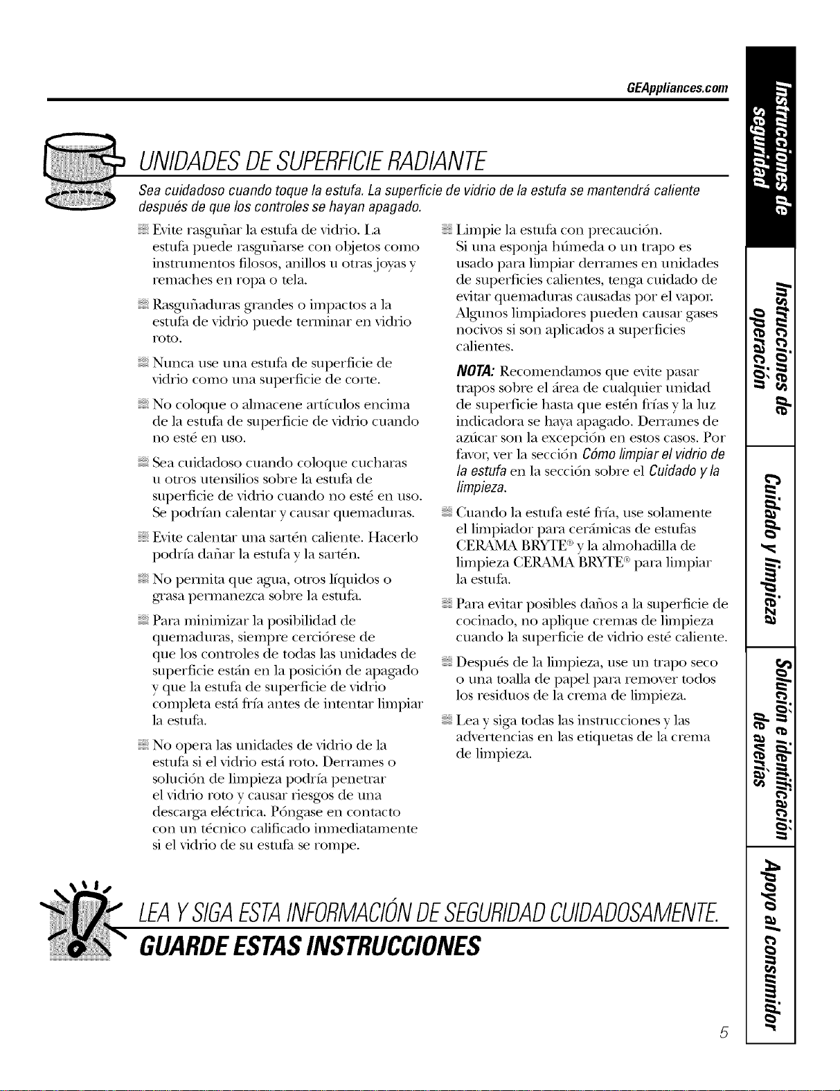
GEAppliances.com
UNIDADESDESUPERFICIERADIANTE
Sea cuidadoso cuando toque la estufa. La superficie de vidrio de/a estufa se mantendr# cafiente
despu#s de que los controles se hayan apagado.
Evim rasguflar la estufa de vidfio. I,a
estuPa puede rasguflarse con objetos como
instrumentos fllosos, anillos u otrasjwas y
remaches en ropa o mla.
Rasgufladuras grandes o impactos a ]a
esudCa de vidrio puede tellninar en vi&io
roto.
Nunca use una esmPa de superficie de
\'idiio como una superficie de corm.
No coloque o almacene artfculos encima
de la estuPa de superficie de vidtqo cuando
no est_ en uso.
Sea cuidadoso cuando coloque cucharas
u otros umnsilios sobre la estutZa de
superficie de vidlJo cuando no est_ en uso.
podrfan calentar y causar quemaduras.
Evim ca]entar una sart&_ ca]ienm. Hacerlo
podrfa daflar la esuffa y la sart_n.
No pem_ita que agua, otros l/quidos o
g_asa permanezca sobre la estufi_.
Para minimizar la posibilidad de
quemaduras, siempre cerci6rese de
que los controles de todas las unidades de
superflcie estdn en ]a posici6n de apagado
y que la esuffa de superficie de vidrio
completa estd fifa anms de intentar limpiar
]a estul_a.
No opera las unidades de vidlJo de la
estul_a si el vidrio est;i roto. Derrames o
soluci6n de limpieza podrfa penetrar
el vidrio roto y causar desg_s de una
descarga el_cuqca. P6ngase en conmcto
con un t_cnico calificado inmediatamente
si el vidrio de su esuffa se rompe.
i,impie ]a esudCa con precauci6n.
Si una esponja hfimeda o un trapo es
usado para limpiar detTames en unidades
de superficies calientes, tenga cuidado de
evitar quemaduras causadas por el vapor
Algm_os limpiadores pueden causar gases
nocix_s si son aplicados a superficies
calientes.
NOTA: Recomendamos que evite pasar
trapos sobre el firea de cualquier unidad
de superficie hasta que est_n flfas y la luz
indicadora se haya apagado. DelTames de
azdcar son la excepci6n en estos casos. Pot
favor, _er ]a secci6n Cdmo limpiar el vidrio de
la estufa en la secci6n sobre el Cuidado y la
limpieza.
Cuando la estufa est_ fl_a, use solamenm
el limpiador para cerdmicas de estufl_s
CERAMA BRYTE cay la almohadilla de
limpieza CE_ BRYTE _°para limpiar
la esutfi_.
Para evitar posibles daflos a ]a superflcie de
cocinado, no aplique cremas de limpieza
cuando la superficie de vidrio est_ calienm.
Despu_s de ]a limpieza, use un uapo seco
o una toalla de papel para temoxer todos
los tesiduos de la crema de limpieza.
i,ea y siga todas las instmcciones v las
advertencias en las efiquems de la crema
de limpieza.
LEAYSIGAESTAINFORMACIONDESEGURIDADCUIDADOSAMENTE.
GUARDEESTASINSTRUCCIONES
5
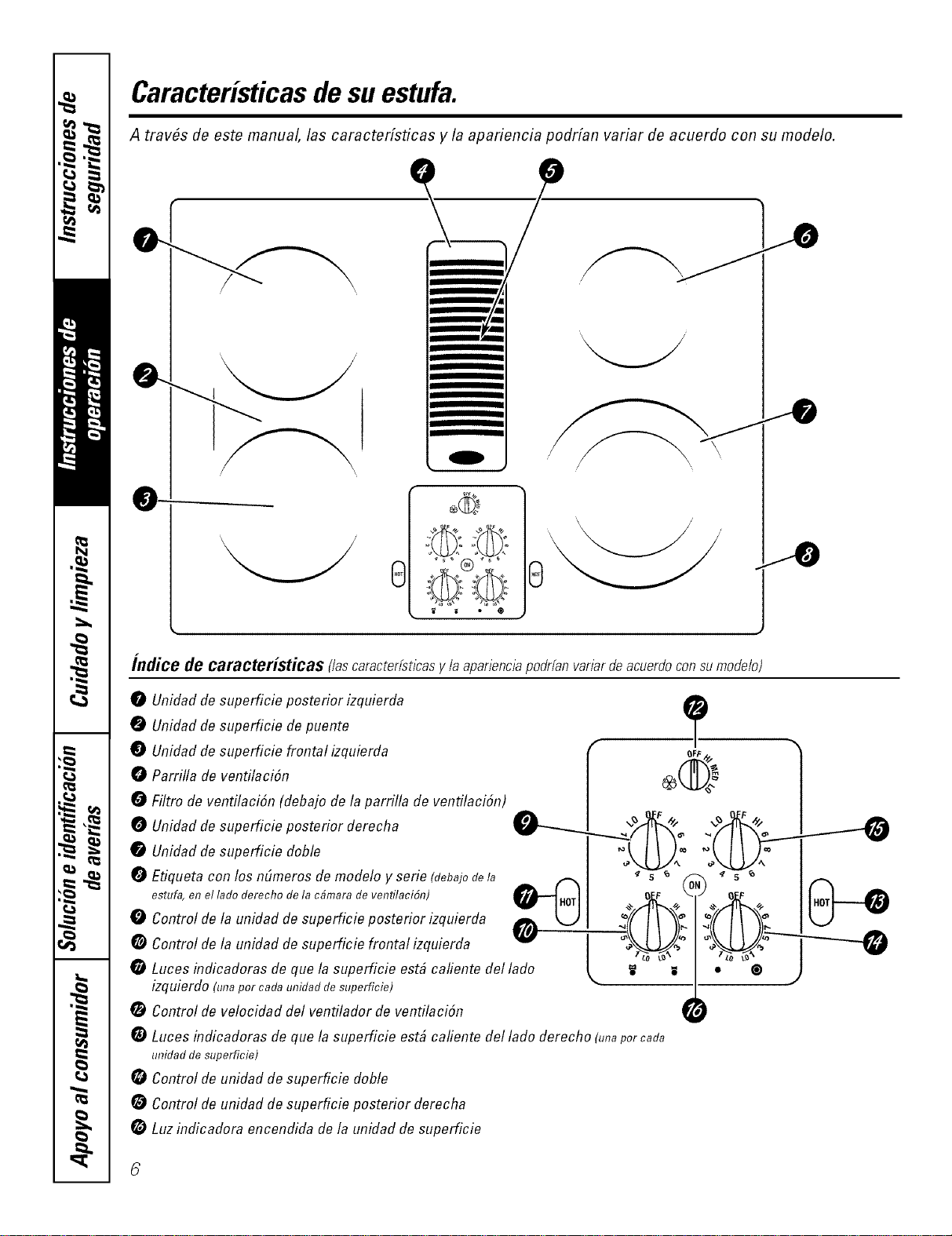
Caracteristicasde su estufa.
A trav#s de este manual, las caracterfsticas y la apariencia podrfan variar de acuerdo con su modelo.
m
m
m
I w
e©©®
.fo
indite de caracteristicas f/ascaracterfst/cas y la apar/enc/a podrfan var/arde acuerdo con su modelo)
0 Unidadde supefficie posterior izquierda
0 Unidadde supefficie de puente
T
Unidadde superficie frontal izquierda (_ oft÷
_ Parrilla de ventilaciSn I _@2 _ I
Filtro de ventilaciSn (debajo de la parrilla de ventilaciSn) | |
O Unidadde superficie posterior derecha _ F _ _ _ F
0 Unidadde superficie doble I ++LU:°+LU:
Etiqueta con los nbmeros de modelo y serie (Uebajode la _ I " s _ _ x " s _ ....
estufa,enel,adoderechode,ac4maradeventilaci4n) _'-'_.n'rlI oz, k _ o_ fuo._
CJI
Control de la unidad de supeficie posterior izquierda _ :(f __ "_: _'_ "_:
0
eControllo s.pe , ,efront l ] W W
Luces indicadoras de que la superficie estd cafiente del lade _. _ _ • ®
izquierdo (unaper cada unidad desuperficie)
Control de velocidad del ventilador de ventilaciSn _ )
G Luces indicadoras de que la superficie est# cafiente del lade derecho (unapercada
unidad de superficie)
Control de unidad de superficie doble
Control de unidad de superficie posterior derecha
Luzindicadora encendida de la unidad de supefficie
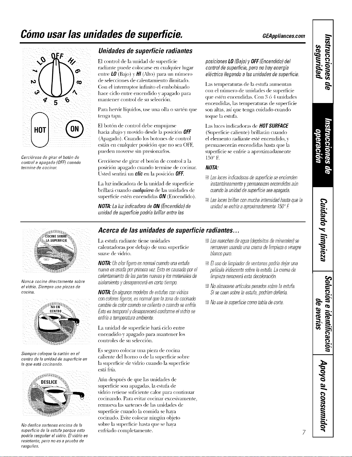
C6mousarlas unidadesde superficie. CEAm a.o s.oo
CerciSrese de girar el botSn de
control a apagado (OFF) cuando
termine de cocina_
Unidades de superficie radiantes
E1 control de la unidad de superficie
radiante puede colocax_e en cualquier lug'ar
entre LO (g_!}o) y HI (Alto) pan_ un n(lmero
de selecciones de calentamiento ilimitado.
Con el intemq)tor infinito el embobinado
hate ciclo entre encendido y apag_ado l)an_
nlan[ener control de su selecci6n.
Para herxir lfquidos, use una olla o sart(q] que
tenKa, taI)a.
E1bot6n de comm] debe empujax_e
hacia abajo y mo_ido desde la posici6n OFF
(Apa_;Jdo). (_uando los bournes de comml
est_in en cualquier posM()n que no sea OFK
pueden moverse sin presionarlos.
Cerci6rese de g-inu" el bot()n de control a la
posici6n apaKado cuando tern-line de cocinax:
Usted sentinl tti] clic eI] la posici6n OFF.
[,a luz indicadora de la ui]idad de superficie
bfillanl cuando cualquiera de las unidades de
superficie est4n encendidas ON (Encendido).
NOTA:LaluzindicadoradeON(Encendido)de
unidaddesuperficiepoddabrillarentrelas
posicionestO (Bajo)yOFF(Encendido)del
controldesuperficJe,peronohayenergJa
e/#ctrica/legandoalasunidadesdesuperficie,
i,as tempel;iQlraS de ]a es{tlt;t at/l//entan
con el nOmero de tmidades de supedicie
que est{_nencendidas. Con 3 6 4 unidades
encendidas, las tempenmlras de superficie
son altas, asf que teI]g;_ cuidado cuando
toque ]a esttdh.
i,as luces indicadoras de HOTSURFACE
(Superficie caliente) brillarfin cuando
el elemento radiante est4 encendido, y
pem]anecerfin encendidas hasta que la
superficie se enii'fe a aproximadameme
150° E
NOTA:
Laslucesinflicaflorasdesuperficieseencienflen
/nstant,Oneamente/permanecenencendflasa_n
cuanflo/auniflaflfiesuperficieseaapagafla.
Laslucesbrillanconmuchaintensiflaflhastaquela
unifiadseenfriaaaproximaflamente150°£
Nunca cocine directamente sobre
el vidrio. Siempre use piezas de
cocina.
2,,,,i,,,,,,,,,,,,,,¸,2¸¸¸2
CENTBO !i
Siempre coloque la sart#n en el
centro dela unidad de superficie en
la queestb cocfl_ando.
No deslice sartenes encima de la
superficie de la estufa porque esto
podrfa rasgufiar el vidrio. El vidrio es
resistente, pero no es a prueba de
rasgufios.
Acerca de las unidades de superficie radiantes...
I,a esmib radiante tiene unidades
calemadoms pot debajo de una superficie
sume de _idfio.
NOTA:Unolorligeroesnormalcuanflounaestufa
nuevaes usaflaporprimeravez&to es causafloporel
ca/entamientode/aspartesnuevasy losmateria/esde
ais/amientoyflesaparecerbenco/totiempo.
NOTA:Enalgunosmoflebsdeestufasconviflrios
concoloresligeros,esnormalquelazorn decocinaflo
cambiedecolorcuanflosecalientaocuanfloseenfrfa.
Estoestemporaly flesaparecerbconformeel viflriose
enfrfaa temperaturaarnbiente.
I,a unidad de superficie hanl ciclo enU'e
encendido y apag_ado pare mantener los
commies de su selecci6n.
Lasmanchasdeagua(flep6sitosdeminerales)se
remuevenusanflounacremadelimpiezaovinagre
blancopuro.
ElusodeIimpiadordeventanaspodrfadejaruna
pelfcubiridiscentesobreb estufa.Lacremade
limpiezaremover#estaflecoloraci6n.
Noalmaceneartfcu/ospesaflossobrelaestufa.
Sisecaensobre/aestufa,poflrfanflafiafla.
Nouseb supefficiecomotabladecorte.
Es seg-uro colocar una pieza de cocina
calieme del homo o de la superficie sobre
la superficie de xidrio cuando la superficie
estfi frfa.
A(m despu& de que las unidades de
superficie son apag'adas, la esmii_ de
vidrio redene suficiente calor para confinuar
cocinklndo. Pare evitar cocinay excesiFdl-i-|ente,
remue_;{ las sartenes de las unidades de
superficie cuando la comida se hma
cocinado. Exite colocar niI]g-(m olijeto
sobxv la superficie hasta que se hava
enfiiado complemmenm.
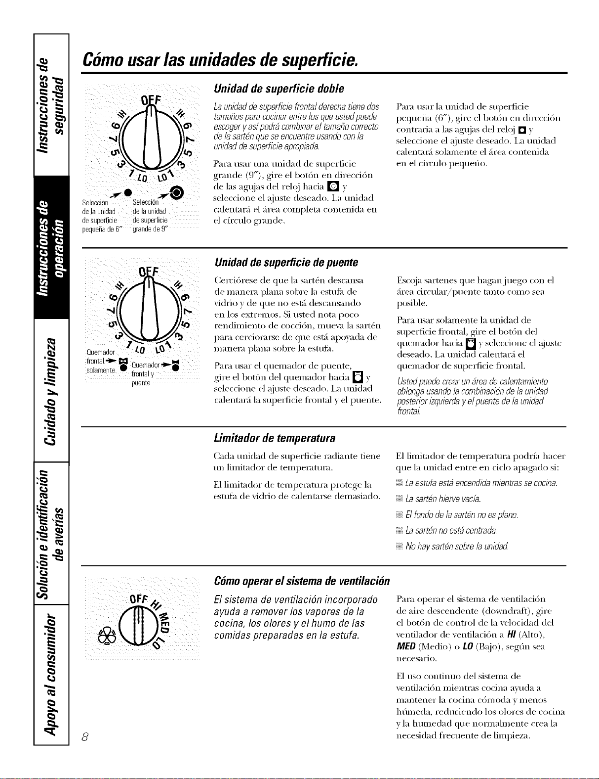
Comousarlas unidadesde superficie.
delaunidad de la unidad
desuperficie desuperficie
pequeSade6" grandede9"
Unidad de superficie doble
Launidaddesupefflc/efrontalderechatienedos
tamafiosparacoclharentrelosqueustedpuede
escogeryas[podrficombinarel tamafiocorrecto
de/asartdnqueseencuentreusandocon/a
unidaddesupeffMeapropiada.
Para usar una unidad de supedide
grande (9"), gire el bot6n en direcci6n
de las agujas del reloj hacia [] y
selecdone el ajuste deseado, i,a unidad
calentar;i el ;h'ea completa contenida en
el cfl'culo grande.
Para usar la unidad de superficie
pequefia (6"), gire el bot6n en direcci6n
contraria alas agqias del reh)j [] y
seleccione el _ouste deseado. I,a unidad
calentaM solamente el firea contenida
en el cfl'culo pequeflo.
frontal-1_,_I=11
-_ Quemador't=_i
SOarnen!e frontal7
puente
Unidad desuperficie de puente
Cercidrese de que la sartOn descansa
de manera plana sobre la estufi_ de
vidrio v de que no est:i descansando
en los extremos. Si usted nota pc)co
rendinliento de cocd6n, II/tleVa la sarten
para cerciorai_e de que est:i apoyada de
nlanera plana sobre la estufil.
Para usar el quemador de puente,
gire el botdn del quemador hada [] y
selecdone el ajuste deseado, i,a mfidad
calentaM la supe_fide frontal v el puente.
Escoja. sartenes (lue hagan,.jue°°_ con el
firea circular/puente tnnto coino sea
posible.
Para usar solamente la mfidad de
superficie frontal, gire el bot6n del
quemador hacia [] y seleccione el @lste
deseado. I,a mfidad calentar_i el
quelnador de supei_ficie fl'ontal.
Ustedpuede crear un_rea decalentamiento
ob/ongausando/acombbadbn de/a unidad
posterior 12quierday e/puentede/a unidad
frontal
Limitador de temperatura
Cada mfidad de supedicie radiante tiene
un limitador de temperamra.
E1 limitador de tempemtura protege la
estuth de vi(hio de calentm_e demasiado.
E1 limitador de temperamra podrfa hacer
que la mfidad entre en ciclo apagado si:
Laestufa esN encendidamientrassococ/na.
Lasart#n hiervevacb.
El fondode lasart#n no espiano.
Lasartdn no est#centrada.
No haysartbn sobre /aunidad
8
Como operar el sistema de ventilation
El sistema de ventilaci6n incorporado
ayuda a remover los vapores de la
cocina, los olores y el humo de las
comidas preparadas en la estufa.
Para operar el sistema de venfilad6n
de aire descendente (downdrafl), gire
el bot6n de control de la velocidad del
ventilador de ventilad6n a HI(Nto),
MED (Medio) o LO (Bajo), segfin sea
necesaYiO.
E1 uso confinuo del sistema de
ventilaci6n mientras codna avuda a
iilanteneY la Cocina coii/oda v II/enos
hfimeda, reduciendo los olores de codna
v la huinedad que nornmhnente crea la
necesidad frecuente de limpieza.
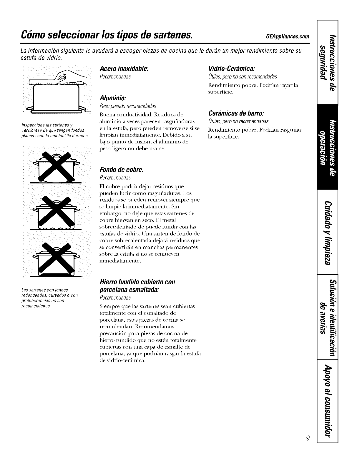
Comoseleccionar lostiposde sartenes. CEA_,_,_,,o,s.oo,,
La informaciSn siguiente le ayudar# a escoger piezas de cocina que le dar#n un mejor rendimiento sobre su
estufa de vidrio.
i¸)i
/i. i
flTspeccione las sartenes y
cerciSrese de que tengan fondos
pianos usando una tablilla derecha.
Acero inoxidable:
Recomendadas
Aluminio:
Peso pesado recomendadas
Buena conductividad. Residuos de
aluminio a veces parecen rasgufiadm'as
en la estttfiL pero pueden removei_e si se
limpian imnediatamente. Debido a su
bajo ptmto de fllsi6n, el aluminio de
peso ligero no debe usable.
Vidrio-Ceramica:
Lltiles, pero no son recomendadas
Rendimiento pobre. Podrfan ravar la
supe_fide.
Ceramicasde barro:
Lltiles, pero no recomendadas
Rendimiento pobre. Podrfan rasguflar
la superficie.
Fondode cobre:
Recomendadas
E1 cobre podrfa dejar residuos que
pueden lucir como rasgufiaduras. I,os
residuos se pueden remover sieinpre que
se limpie la imnediatamente, Sin
embargo, no deje que estas sartenes de
col)re hiervan en seco. E1 metal
sobrecalentado de puede fimdir con las
estttfi_s de vidrio. Una sart_n de fimdo de
col)re sobrecalentada dejarfi residuos que
se convei'tii';/n en iilanchas peililanentes
sobi'e la esttlfil si no se I'eIlltleven
iron ediatam ente.
Las sartenes co!?folTdos
redondeados, curvados o con
protuberancias no sot?
recomendadas.
Hierro fundidocubiertocon
porcelana esmaltada:
Recomendadas
Siempre que las sartenes sean cubiertas
totalmente con el esmaltado de
porcelana, estas pie,';is de cocina se
i'eCOlllienda n. RecolllendalilOS
precaucidn para piezas de cocina de
hierro flmdido que no estgm totalmente
cubiertas con tma capa de esmalte de
porcelana, ya que podrfan rasgar la estufil
de vidri_>cerfimica.
9
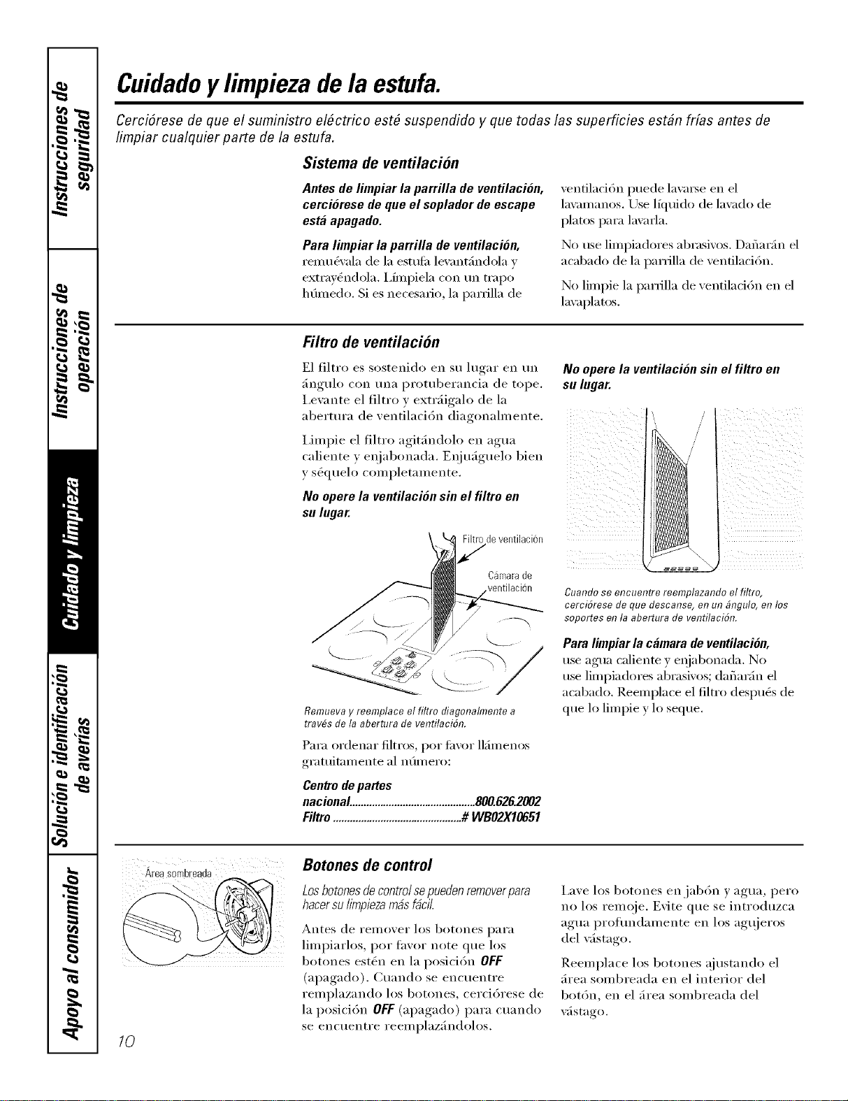
Cuidadoy limpiezade la estufa.
CerciSrese de que el suministro el#ctrico est# suspendido y que todas las superficies est#n fdas antes de
fimpiar cualquier parte de la estufa.
Sistema de ventilaci6n
Antes de limpiar la parrilla de ventilaci6n,
cerci6rese de que el soplador de escape
esta apagado.
Para limpiar la parrilla de ventilaci6n,
remu&'ala de la estufi_ lexm_t;indola y
extrav_ndola. I,frnpiela con un trapo
hOmedo. Si es necesario, la pan'ilia de
ventilaci6n puede lavm3e en el
la\_mmnos. Use lkluido de lavado de
platos para lavarla.
No use limpiadores abrasivos. Daflar_in el
acabado de la parrilla de venfilaci6n.
No limpie la parfilla de ventilaci6n en el
lavaplatos.
Filtro de ventilaci6n
E1 filtro es sostenido en su lugar en un
fingulo con tma protuberancia de tope.
I,e\m_te el filtro y extr;ligalo de la
abertm'a de ventilaci6n diagonalmente.
I,impie el filtro agit;indolo en agua
caliente )ei_jabonada. Eqju;iguelo bien
y st_cluelo completamente.
No epere la ventilaci6n sin el filtre en
su lugar.
Fikr0deventilacion
C&Y_arade
ventiiacion
Remueva y reemplace el filtro diagonalmente a
travfis de la abertura de ventilaci6n.
Para ordenar filtros, pot fiwor llfimenos
gratuitamente al nOmero:
Centre de partes
nacional.............................................800.626.2002
Filtro ..............................................# WBO2X10851
No operela ventilaci6n sin el filtro en
su lugar.
Cuando se encuentre reemplazando el filtro,
cerci6rese de que descanse, en un &Tgulo, en los
soportes en la abertura de ventilaci6n.
Para limpiar la camara de ventilaci6n,
use agua caliente y eqjabonada. No
use limpiadores abrasivos; (lafiaMn el
acabado. P.eemplace el film) despug_s de
que lo limpie y lo seque,
Areasombreada
/0
Botones de control
Losbotonesdecontrolsepuedenremoverpara
hacersulimpiezam#sf#ci/.
Antes de i'ei/lovei" los botones paI'a
limpiarlos, pot ta\'or note que los
botones est_n en la posici6n OFF
(apagado). Cuando se encuentre
remplazando los botones, cerci6rese de
la posici6n OFF (apagado) para cuando
se encuentre reelnplaz;hldolos.
I,ave los botones en.iab6n y agua, pero
no los remoje. Evite que se introduzca
agua proflmdamente en los agqjeros
del wlstago.
Reemplace los botones ajustando el
_h'ea sombreada en el interior del
bot6n, en el ;h'ea sombreada del
wlstago.
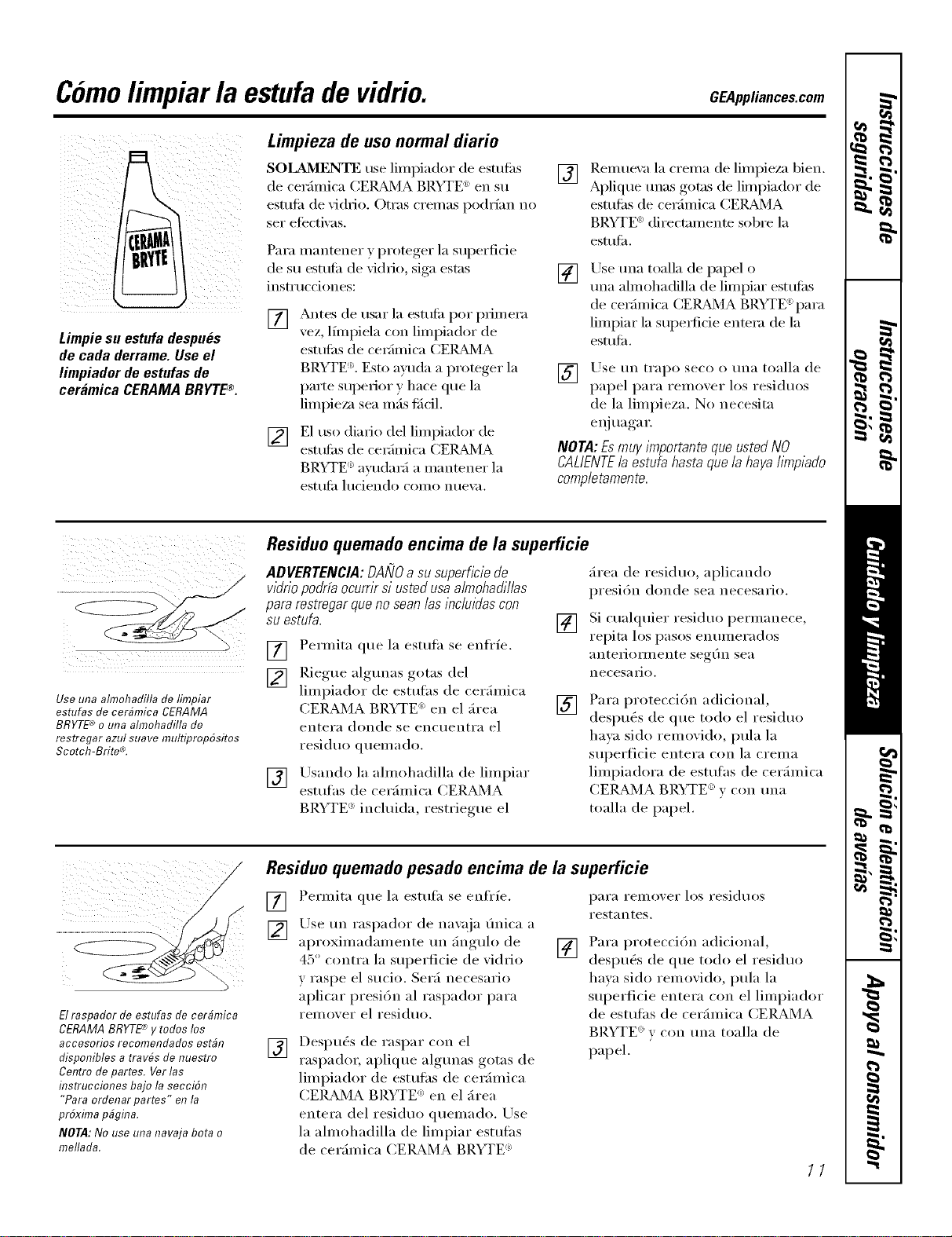
Comolimpiar la estufade vidrio. GEAppliances.com
Limpiesuestufadespu_s
de cadaderrame.Useel
limpiadordeestufasde
ceramica CERAMABRYTEQ
Limpieza de uso normal diario
SOLAMENTE use limpiador de estufi_s
de cerfimica CEI_dMA BRYTE _)en su
estufi_ de xi(lrio. Otras cremas podrfan no
sex"eti_cti_ as.
Para mantener v, I)r°teger, la superficie
de su estufi_ de xidrio, siga estas
instrtlcciones:
[] Antes de usar la estufi_ pot primera
vez, lflnpiela con limpiador de
estufi_s de cerfimica CEI_dVIA
BRYTE 'LEsto ayuda a proteger la
parte superior y hace que la
limpieza sea mils tilcil.
[] E1 uso diado del limpiador de
estufi_s de cerfimica CEI_d_IA
BRYTE '_avudarfi a nlantener la
estufi_ luciendo como nue\:_.
[]
Relnuexa la crelna de limpieza bien.
Aplique unas gotas de limpiador de
estufi_s de cerfimica CE]_dMA
BRYTE _' directamente sobre la
estufiL
[]
Use tma toalla de papel o
tma almohadilla de limpiar estufi_s
de cerfimica (:EI_d_/IA BRYTE ':para
limpiar la superlicie entera de la
estufiL
[] Use tm trapo seco o tma toalla de
papel para remover h)s residuos
de la limpieza. No necesita
enj ua ga r.
NORA: Esmug importante qua usted NO
CALIENTEla estufa hasta quela haya limpiado
compietamente.
Use una aflnohadilla de timpiar
esmfas de cer#mica CERAMA
BRYTE® o una almohadilla de
restregar azut suave muttipropdsitos
Scotch-Brite ®.
Residuo quemado encima de la superficie
ADVERTENCIA:DANOa susuperficiede
vidriopodrfaocurrirsiustedusaalmohadillas
pararestregarquenosean/asinciuidascon
suestufa.
[] Permita que la esmfh se enfrfe.
[] Pdegue, aloulmS_ ,g°tas del
lin_piador de esmfhs de cerfimica
CERAMA BRYTE ') en el firea
entera donde se encuentra el
i'esidtlo qtlei//ado.
[] ILrsando la almohadilla de limpiar
estufas de cerfimica (_ERAMA
BRYTE ': inchfida, restriegue el
[]
[]
firea de residuo, aplicando
presi6n donde sea necesario.
Si cualquier residuo permanece,
repita los pasos enmnerados
antelJOlillente seg(m sea
necesaiJo.
Para protecci6n adicional,
despu_s de que todo el residuo
haya sido removido, pula la
s/lperlicie entera con la ci'eiil_l
limpiadora de esttflhs de cerfimica
CERAMA BP.YTE _)v con tma
toalla de papel.
Elraspadordeestufasdecerbmica
CERAMABRYTE'_ytodoslos
accesoriosrecomendadosestbn
disponiblesatray,sdenuestro
Centrodepartes.Verlas
instruccionesbajolasecciSn
"Paraordenarpartes" enla
proxlma pagma.
NOTA: No use una navaja bota o
mellada.
Residuo quemado pesado encima de la superficie
[]
[]
[]
Permita que la esmfh se enfl'fe.
Lrse tm raspador de na;aja (mica a
aproximadamente tm finguh) de
45 ° contra la superficie de vidfio
y raspe el sucio. Serfi necesario
aplicar presi6n al raspador para
i'ell/OVei" el residuo.
Despu&s de raspar con el
raspador, aplique algtmas gotas de
limpiador de esmfhs de cerfimica
CERAMA BP,YTE ')en el firea
entera del residuo quemado. Use
la ahnohadilla de limpiar esttdhs
de cerfimica CEIL_MA BRYTE '_
[]
p_lI'_l I'eIIIO_,er los residtloS
Festantes.
Para protecci6n adicional,
despu& de que todo el residuo
hava sido removido, pula la
superficie entera con el limpiador
de estulhs de cerfimica CERAMA
BRYTE ':v con tma toalla de
papel.
11
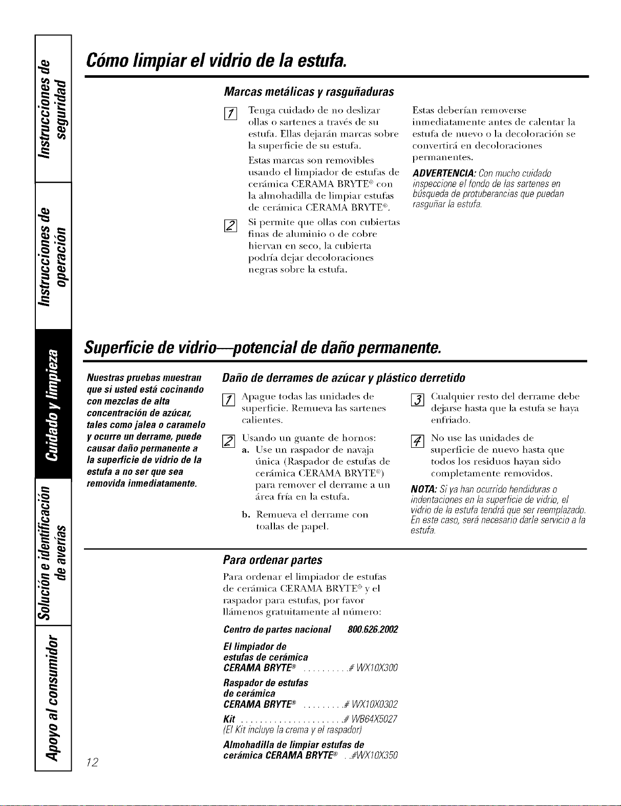
Comolimpiar el vidriode la estufa.
Marcas metalicas y rasgu#aduras
[] Tenga cuidado de no deslizar
ollas o sartenes a trav(_s de su
estufiL Elias dejarfin marcas sol)re
la superficie de su estufh.
Estas marcas son removibles
usando el limpiador de esmfhs de
cerfimica CERAMA BRYTE e_con
la ahnohadilla de limpiar estulhs
de cerfimica CERAMA BRYTE 'L
[] Si permite que ollas con cubiertas
finas de ahnninio o de col)re
hiervan en seco, la cubierta
podrfa dejar decoloraciones
negras sobre la esmfh.
Estas deberlan rei//overse
imnediatamente antes de calentar la
estulh de nuew) o la decoloraci6n se
convertirfi en decoloraciones
p eI'II/}1n e ntes.
ADVERTENCIA: Con mucho cuiflaflo
inspeccione el rondo de/as sartenes en
bElsquedade protuberancias que puedan
rasgufiar /a estufa.
Superficie de vidrio--potencial de da o permanente.
Nuestras pruebas muestran
que si usted esta cocinando
con mezclas de alta
concentraci6n de az(/car,
tales como jalea o caramelo
y ocurre un derrame, puede
causar daOo permanente a
la superficie de vidrio de la
estufa a no ser que sea
removida inmediatamente.
Da#o de derrames de azucar y plastico derretido
[] Apague todas las tmidades de [] Cualquier resto del derrame debe
superficie. Remuexa las sartenes deja_e hasta que la estufi_ se ha)a
calientes, enfl'iado.
[] Usando tm guante de hornos:
a. Use un raspador de nawlja
finica (Raspador de esttdhs de
cerfimica CERAMA BP.YTE _))
I)_lI'_l FeIl/oveI" el deiTai//e a tin
firea ti'fa en la estufa.
b, ReillHe_,a el delTaiile con
toallas de papel.
[] No use las unidades de
superficie de nuevo hasta que
todos los residuos hawm sido
completamente removidos.
NORA: Si ga han ocurrido hencfiduraso
incfentaciones en la superficie de vicfrio,el
vidrio de/a estufa tenc/r_que ser reemplazacto.
Eneste caso, serd necesado dar/e servlcio a/a
estufa.
12
Para ordenar partes
Para ordenar el limpiador de estufas
de cerfimica CERAMA BRYTE _y el
raspador para esmfhs, pot favor
llfimenos gratuitamente al nfimero:
Centro de partes nacional 800.626.2002
El limpiador de
estufas de ceramica
CERAMA BRYTEc_ .......... //WXI 0)(300
Raspador de estufas
de ceramica
CERAMA BRYTEc_ ......... # WX70)(0302
Kit ...................... # WB64XS027
(ElKit incluye lacrema y el raspador)
Almohadilla de limpiar estufas de
ceramica CERAMA BRYTE_ , ,#WX70)(350
Instrucciones
de instalacion
Estufa radiante de
ventilacion descendente
I Si tiene alguna pregunta, Ilame al 800.GE.CARES (800.432.2737) o visite nuestro sitio en la Web: GEAppliances.com
ANTES DE COMENZAR
Lea estas instrucciones complete y
cuidadosamente.
• IMPORTANTE - Guardeestas
instrucciones para ser usadas por el
inspector electrico.
• IMPORTANTE - Observetodos
los c6digos y ordenanzas aplicables.
• Note al instalador - Cerci6rese de dejar
estas instrucciones con el Consumidor.
• Note al consumidor - Guarde estas
instrucciones pare referencia future.
• A no ser que usted sea una persona muy
bien entrenada en la instalaci6n de este
producto, busque la ayuda de un instalador
profesional.
• La instalaci6n apropiada es la
responsabilidad del instalador.
• Si este producto falla por una instalaci6n
inapropiada, la Garantia no cubrira este
producto.
ADVERTENCIA - Antesde
comenzar la instalaci6n, desconecte el
interruptor de suministro electrico en el
panel de servicio y cierre el mecanismo
de seguridad pare evitar que alguien Io
conecte accidentalmente. Cuando no
exista un dispositivo de cierre de
seguridad, amarre un aviso visible,
como una etiqueta al panel de servicio
haciendo la advertencia.
INSTRUCCIONES IMPORTANTES
DE SEGURIDAD
ADVERTENCIA - PARA
REDUCIR EL RIESGO DE INCENDIOS,
DESCARGAS ELI_CTRICAS O LESIONES
PERSONALES, OBSERVE LO SIGUIENTE:
[] El trabajo de instalaci6n y el alambrado
electrico debe hacerlo una persona(s)
calificada conforme a todos los c6digos
y estandares aplicables, incluyendo una
construcci6n aprobada por el inspector
de incendios.
[] Suficiente aire es necesario pare
una combusti6n apropiada y pare
deshacerse de los gases a traves de
una salida de humo (chimenea) de
equipos que queman combustibles
pare prevenir retroalimentaci6n. Siga
las recomendaciones del fabricante
del equipo de calentamiento y los
estandares de seguridad tales como los
publicados por la Asociaci6n nacional
de protecci6n de incendios (NFPA), y la
Sociedad americana de ingenieros de
calefacci6n, acondicionadores de aire y
refrigeraci6n (ASHRAE), y los c6digos
de las autoridades locales.
[] Cuando se encuentre cortando o
taladrando en la pared o en el techo, no
dafie los alambrados electricos u otras
utilidades escondidas.
[] Los ventiladores conectados a conductos
deben siempre ester ventilados hacia el
exterior.
• La unidad debe ester conectada a tierra
apropiadamente.
ADVERTENCIA - PARAREDUCIR
EL RIESGO DE INCENDIOS, SOLAMENTE
USE CONDUCTOS METALICOS.
13
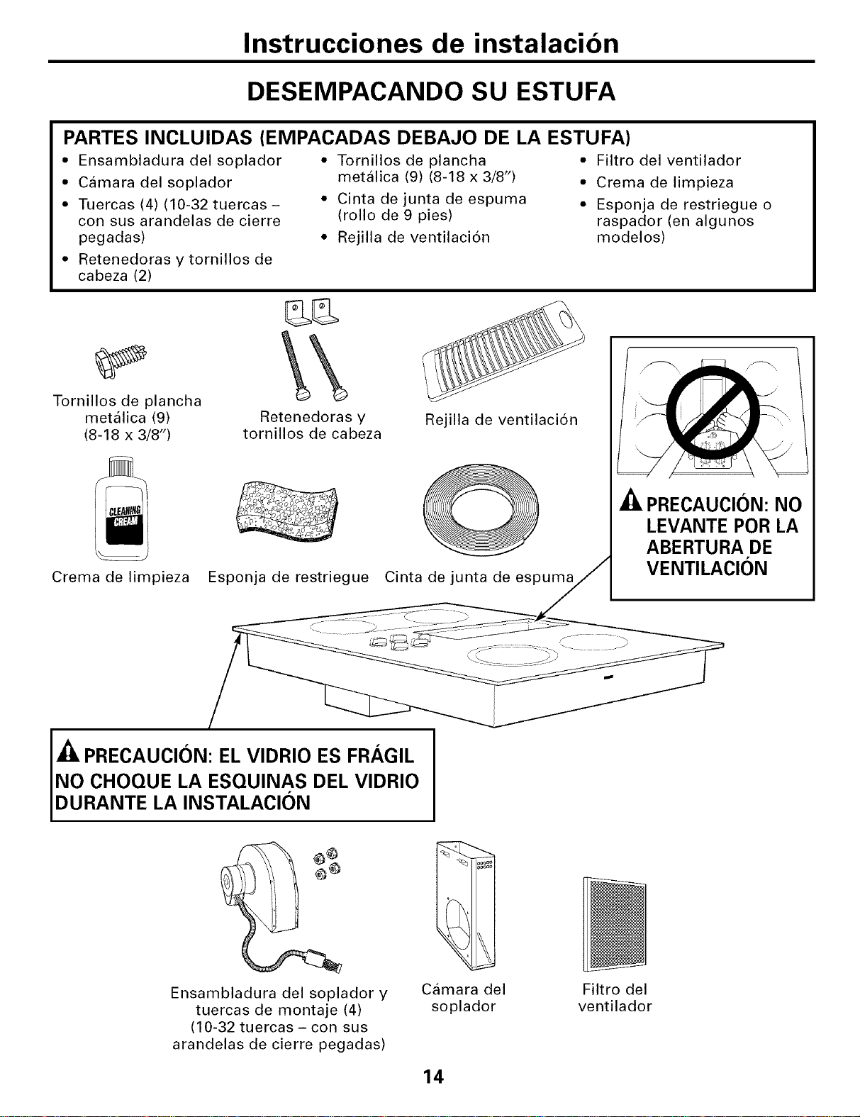
Instrucciones de instalacion
DESEMPACANDO SU ESTUFA
PARTES INCLUlDAS (EMPACADAS DEBAJO DE LA ESTUFA)
• Ensambladura del soplador •
• Camara del soplador
• Tuercas (4) (10-32 tuercas - •
con sus arandelas de cierre
pegadas) •
• Retenedoras y tornillos de
cabeza (2)
Tornillos de plancha
metalica (9) (8-18 x 3/8")
Cinta de junta de espuma
(rollo de 9 pies)
Rejilla de ventilaci6n
• Filtro del ventilador
• Crema de limpieza
• Esponja de restriegue o
raspador (en algunos
modelos)
Tornillos de plancha
metalica (9)
(8-18 x 3/8")
Crema de limpieza
Retenedoras y
tornillos de cabeza
Esponja de restriegue
Rejilla de ventilaci6n
0
Cinta de junta de espuma
_Z_PRECAUCION: NO
LEVANTE POR LA
ABERTURA DE
VENTILACION
PRECAUCION: EL VIDRIO ES FRAGIL
NO CHOQUE LA ESQUINAS DEL VIDRIO
DURANTE LA INSTALAClON
Ensambladura del soplador y
tuercas de montaje (4)
(10-32 tuercas - con sus
arandelas de cierre pegadas)
Camara del
soplador
Filtro del
ventilador
14
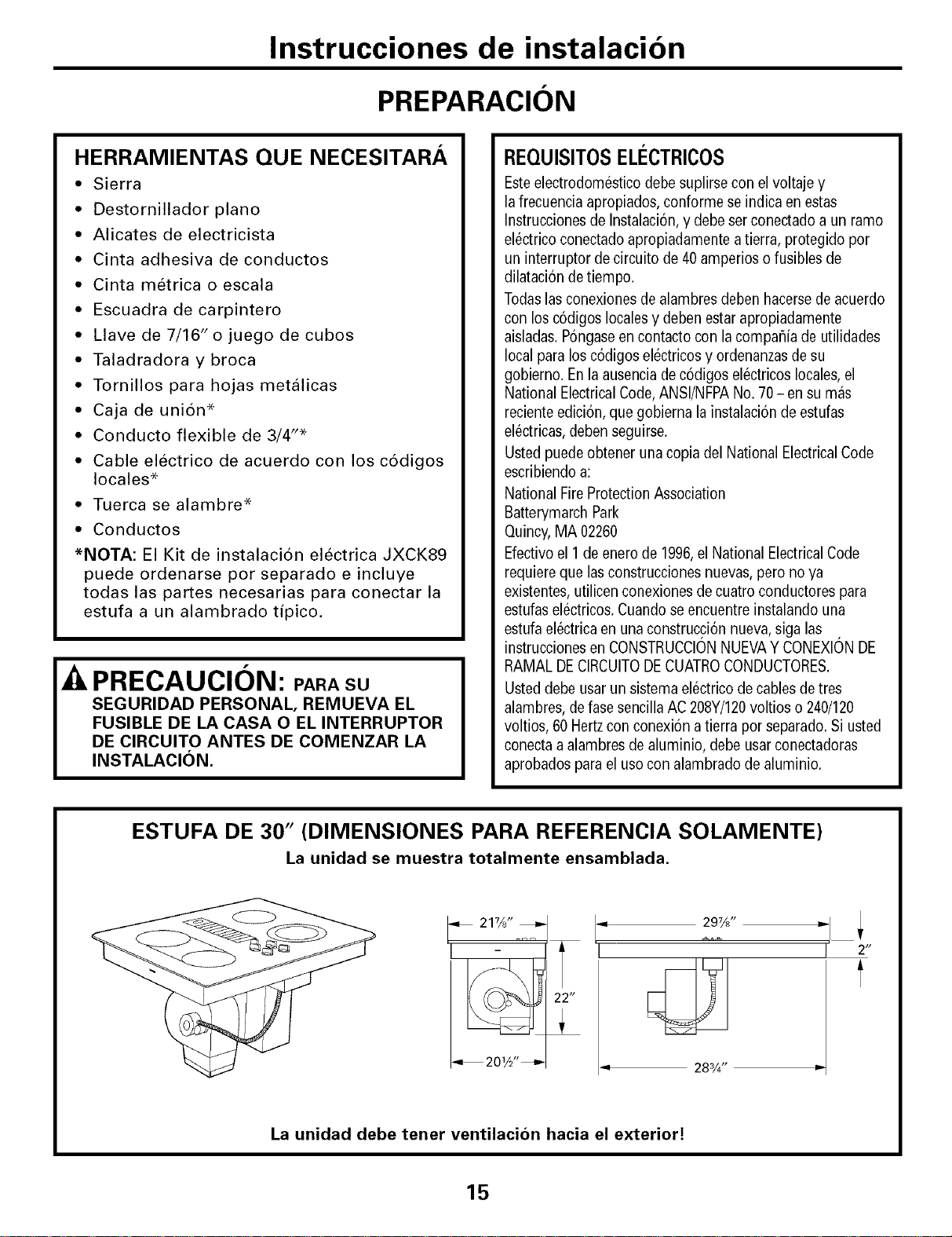
Instrucciones de instalacion
PREPARACION
HERRAMIENTAS QUE NECESITARA
• Sierra
• Destornillador piano
• Alicates de electricista
• Cinta adhesiva de conductos
• Cinta metrica o escala
• Escuadra de carpintero
• Llave de 7/16" o juego de cubos
• Taladradora y broca
• Tornillos para hojas metalicas
• Caja de uni6n*
• Conducto flexible de 3/4"*
• Cable electrico de acuerdo con los c6digos
locales*
• Tuerca se alambre*
• Conductos
*NOTA: El Kit de instalaci6n electrica JXCK89
puede ordenarse por separado e incluye
todas las partes necesarias para conectar la
estufa a un alambrado tipico.
PRECAUCION: PARASU
SEGURIDAD PERSONAL, REMUEVA EL
FUSIBLE DE LA CASA O EL INTERRUPTOR
DE CIRCUITO ANTES DE COMENZAR LA
INSTALACION.
REQUISITOSELECTRICOS
Esteelectrodomestico debe suplirse con el voltaje y
la frecuenciaapropiados, conforme seindica en estas
Instruccionesde Instalaci6n,y debeser conectadoa un ramo
el@tricoconectado apropiadamente a tierra, protegido por
un interruptor de circuito de40 amperios o fusibles de
dilataci6n detiempo,
Todaslasconexiones de alambres deben hacersede acuerdo
con los c6digos locales y deben estar apropiadamente
aisladas,P6ngaseen contacto con la compafiia de utilidades
local para los codigos electricosy ordenanzasde su
gobierno. Enla ausencia decodigos electricos locales,el
National ElectricalCode,ANSI/NFPANo. 70- en su mas
reciente edici6n, que gobierna la instalaci6n de estufas
el@tricas,debenseguirse.
Usted puede obtener una copia del NationalElectricalCode
escribiendo a:
National FireProtectionAssociation
Batterymarch Park
Quincy,MA 02260
Efectivo el 1 de enero de 1996,el National ElectricalCode
requiere que lasconstrucciones nuevas,pero no ya
existentes, utilicen conexionesde cuatro conductores para
estufasel@tricos.Cuandose encuentre instalando una
estufael@tricaen una construcci6n nueva,siga las
instruccionesen CONSTRUCCIONNUEVAYCONEXIONDE
RAMAL DECIRCUITODECUATROCONDUCTORES,
Usted debe usarun sistema el@tricode cables de tres
alambres,de fase sencilla AC208Y/120voltios o 240/120
voltios, 60 Hertzcon conexi6n atierra porseparado, Si usted
conectaa alambres de aluminio, debe usarconectadoras
aprobados para el uso con alambrado dealuminio,
ESTUFA DE 30" (DIMENSIONES PARA REFERENCIA SOLAMENTE)
La unidad se muestra totalmente ensamblada.
_. 21%" _J
-,_ 2 01/2" _
= 297/d'
283/4"
I 2"
t
La unidad debe tenet ventilacion hacia el exterior!
15
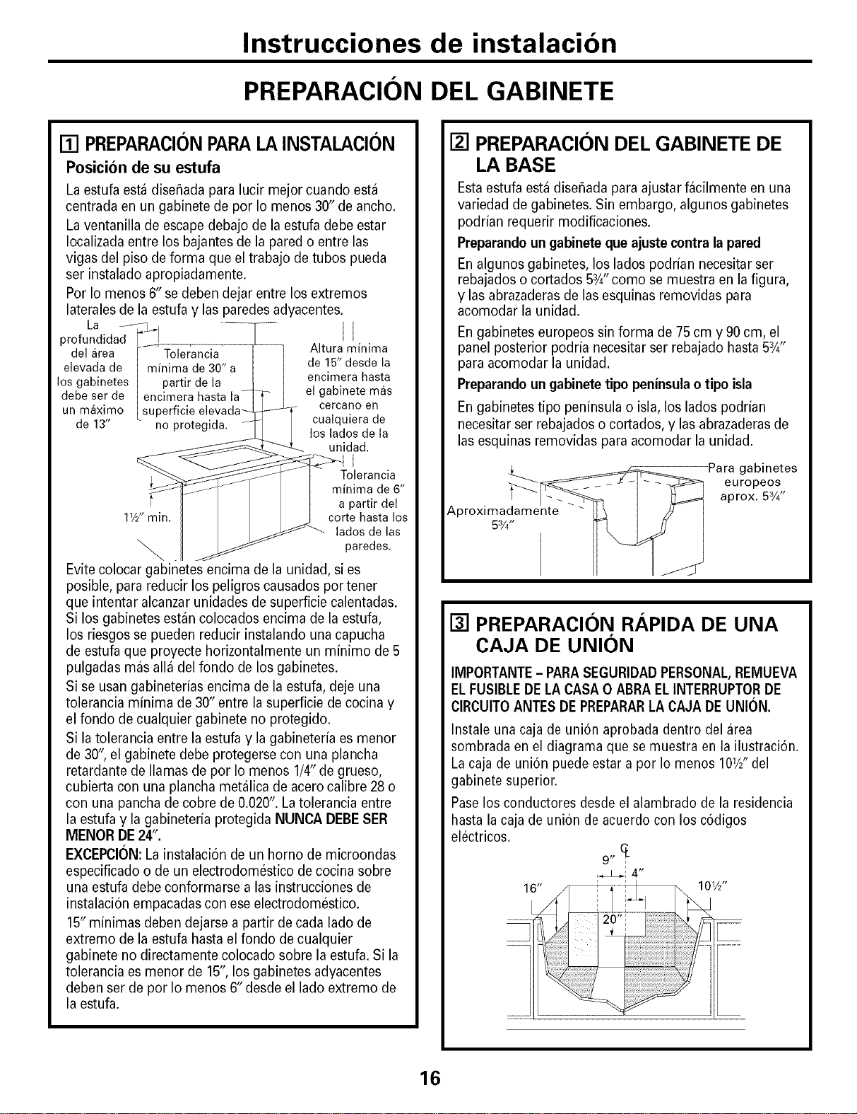
Instrucciones de instalacion
PREPARACION DEL GABINETE
[] PREPARACION PARA LA INSTALACION
Posicionde su estufa
Laestufa esta disehada para lucir mejor cuando esta
centrada en un gabinete de por Io menos 30" de ancho.
La ventanilla de escape debajo de la estufa debe estar
Iocalizada entre los bajantes de la pared o entre las
vigas del piso de forma que el trabajo de tubos pueda
ser instalado apropiadamente.
Por Io menos 6" se deben dejar entre los extremos
laterales de la estufa y las paredes adyacentes.
La
profun i S l II
del area Tolerancia Altura minima
elevada de minima de 30" a de 15" desde la
los gabinetes partir de la encimera hasta
debe ser de el gabinete mas
un maximo superficie cercano en
de 13" cualquiera de
los lados de la
unidad.
I
Tolerancia
minima de 6"
a partir del
11/2" min. corte hasta los
lados de las
paredes.
Evite colocar gabinetes encima de la unidad, si es
posible, para reducir los peligros causados por tener
que intentar alcanzar unidades de superficie calentadas.
Si los gabinetes estan colocados encima de la estufa,
los riesgos se pueden reducir instalando una capucha
de estufa que proyecte horizontalmente un minimo de 5
pulgadas mas alia del fondo de los gabinetes.
Si se usan gabineterias encima de la estufa, deje una
tolerancia minima de 30" entre la superficie de cocina y
el fondo de cualquier gabinete no protegido.
Si la tolerancia entre la estufa y la gabineteria es menor
de 30" el gabinete debe protegerse con una plancha
retardante de llamas de por Io menos 1/4" de grueso,
cubierta con una plancha metalica de acero calibre 28 o
con una pancha de cobre de 0.020". La tolerancia entre
la estufa y la gabineteria protegida NUNCA DEBESER
IVlENORDE24".
EXCEPCI()N: La instalaci6n de un homo de microondas
especificado o de un electrodomestico de cocina sobre
una estufa debe conformarse alas instrucciones de
instalaci6n empacadas con ese electrodomestico.
15" minimas deben dejarse a partir de cada lado de
extremo de la estufa hasta el fondo de cualquier
gabinete no directamente colocado sobre la estufa. Si la
tolerancia es menor de 15", los gabinetes adyacentes
deben ser de por Io menos 6" desde el lado extremo de
la estufa.
[] PREPARACION DEL GABINETE DE
LA BASE
Esta estufa estadisehada para ajustar facilmente en una
variedad de gabinetes. Sin embargo, algunos gabinetes
podrian requerir modificaciones.
Preparandoun gabinete que ajuste contra la pared
En algunos gabinetes, los lados podrian necesitar ser
rebajados o cortados 5W'como se muestra en la figura,
y las abrazaderas de las esquinas removidas para
acomodar la unidad.
En gabinetes europeos sin forma de 75 cm y 90 cm, el
panel posterior podria necesitar ser rebajado hasta 5W'
para acomodar la unidad.
Preparandoun gabinete tipo peninsula o tipo isla
En gabinetes tipo peninsula o isla, los lados podrian
necesitar ser rebajados o cortados, y las abrazaderas de
las esquinas removidas para acomodar la unidad.
Para gabinetes
europeos
aprox. 53/4"
Aproximadamente
53/4"
[] PREPARACION RAPIDA DE UNA
CAJA DE UNION
IMPORTANTE- PARASEGURIDADPERSONAL,REMUEVA
EL FUSIBLEDELA CASA 0 ABRAEL INTERRUPTORDE
CIRCUITOANTES DEPREPARARLACAJA DEUNION.
Instale una caja de union aprobada dentro del area
sombrada en el diagrama que se muestra en la ilustraci6n.
La caja de union puede estar a por Io menos 101/2" del
gabinete superior.
Paselos conductores desde el alambrado de la residencia
hasta la caja de union de acuerdo con los codigos
eBctricos.
9,,CL
,_! 4"
16" 101/2"
16
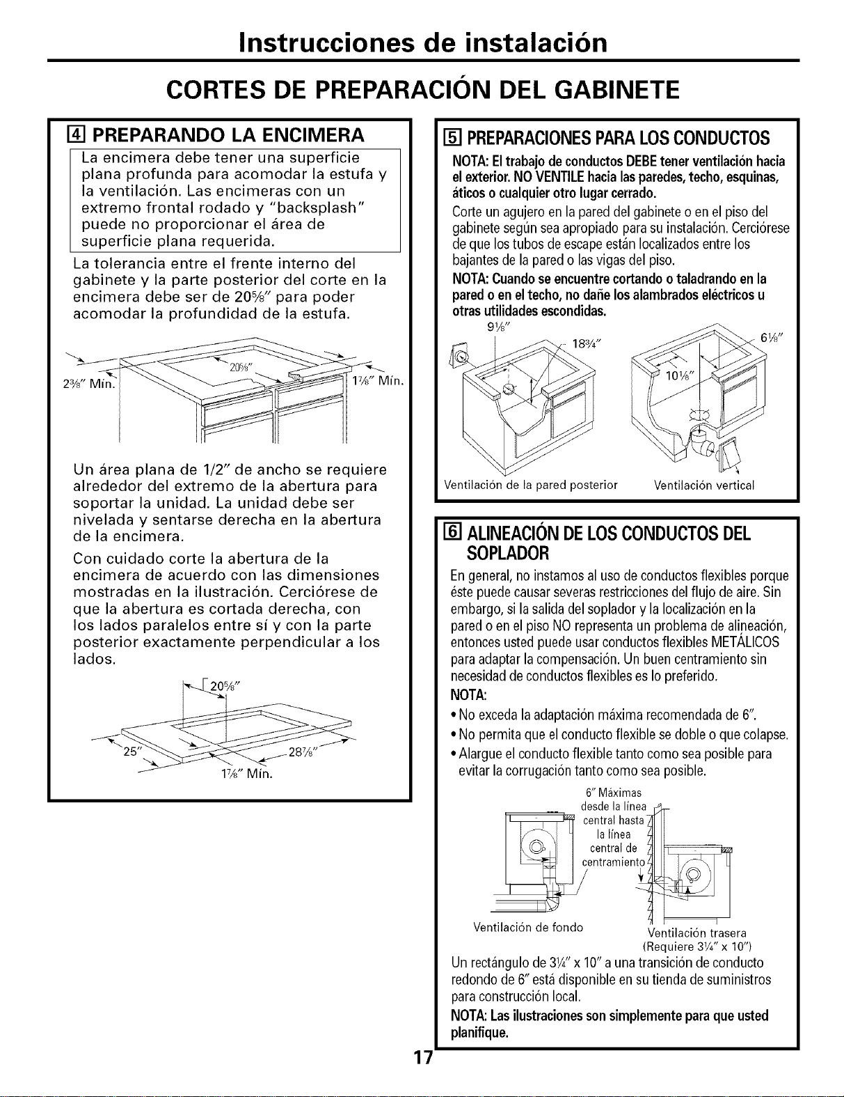
Instrucciones de instalacion
CORTES DE PREPARACION DEL GABINETE
[] PREPARANDO LA ENCIMERA
La encimera debe tener una superficie
plana profunda para acomodar la estufa y
la ventilaci6n. Las encimeras con un
extremo frontal rodado y "backsplash"
puede no proporcionar el area de
superficie plana requerida.
La tolerancia entre el frente interno del
gabinete y la parte posterior del corte en la
encimera debe ser de 20%" para poder
acomodar la profundidad de la estufa.
23/d' Min.
17/d' Min.
Un area plana de 1/2" de ancho se requiere
alrededor del extremo de la abertura para
soportar la unidad, La unidad debe ser
nivelada y sentarse derecha en la abertura
de la encimera.
Con cuidado corte la abertura de la
encimera de acuerdo con las dimensiones
mostradas en la ilustraci6n. Cerci6rese de
que la abertura es cortada derecha, con
los lados paralelos entre siy con la parte
posterior exactamente perpendicular a los
lados,
20%"
17A" Min.
17
[] PREPARACIONESPARALOSCONDUCTOS
NOTA:Eltrabajode conductosDEBEtenerventilacionhacia
elexterior.NOVENTILEhacialasparedes,techo,esquinas,
aticosocualquierotrolugarcerrado.
Corte unagujeroenlapared del gabineteo enel piso del
gabinetesegun seaapropiado para su instalaci6n.Cerci6rese
de que lostubos de escapeestan Iocalizadosentre los
bajantesde la pared o lasvigas del piso,
NOTA:Cuandose encuentre cortandootaladrando en la
pared oen eltecho,no daSelosalambradoselectricos u
otrasutilidadesescondidas.
91/d'
183/4"
Ventilaci6n de la pared posterior Ventilaci6n vertical
[] ALINEACIONDELOSCONDUCTOSDEL
SOPLADOR
Engeneral, no instamos al uso de conductos flexibles porque
estepuede causarseverasrestriccionesdel flujo de aire.Sin
embargo, si la salida del soplador y la Iocalizaci6nen la
pared o en el piso NO representaun problema de alineaci6n,
entoncesusted puede usarconductos flexibles MET_,LICOS
paraadaptar la compensacion. Un buen centramiento sin
necesidadde conductos flexibles es Iopreferido.
NOTA:
• No excedalaadaptaci6n maxima recomendadade 6".
• No permitaque el conducto flexible sedoble o que colapse,
•Alargue el conducto flexible tanto como seaposible para
evitar la corrugaci6n tanto como sea posible.
6" Maximas
des@ la linea
central hasta
la linea ,
centralde ', _
entramleni_
1
Ventilaci6n de fondo Ventilaci6n trasera
(Requiere 31/4" x 10")
Un rectangulo de 31A" x 10"a una transici6n de conducto
redondo de 6" esta disponible en sutienda de suministros
para construcci6n local,
NOTA:Lasilustracionessonsimplementeparaqueusted
planifique.
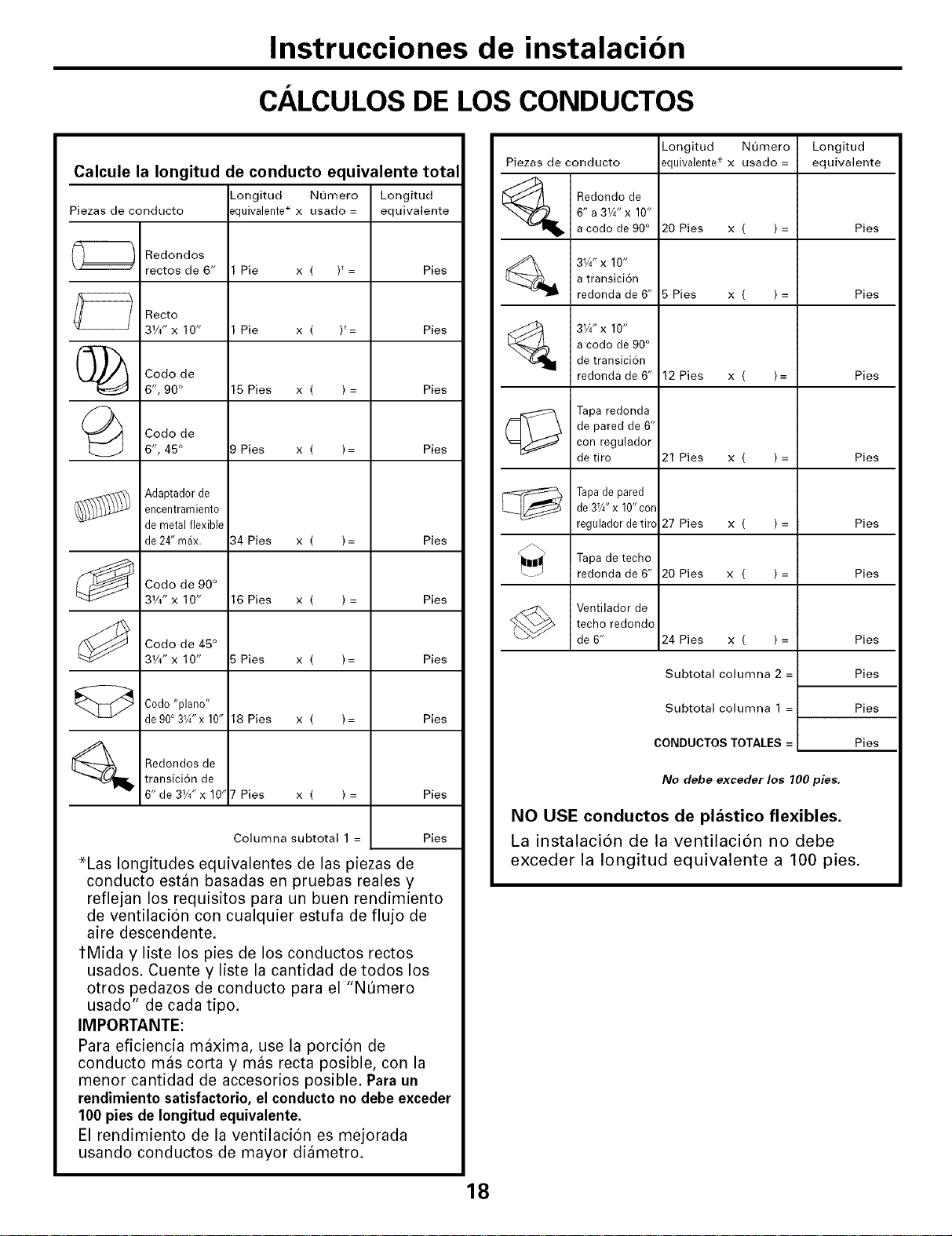
Instrucciones de instalacion
CALCULOS DE LOS CONDUCTOS
Calcule la Iongitud de conducto equivalente total
_ongitud Numero Longitud
Piezas de conducto ._quivalente*x usado = equivalente
Redondos
rectos de 6"
Recto
31/4"x 10"
Codo de
6", 90°
Codo de
6", 45°
Adaptader de
encentramiento
demetal flexible
de24" max.
Codo de 90°
31/4"x 10"
Codo de 45°
31/4"x 10"
Cedo"piano"
de9003W'x 10"
Redondos de
transici6n de
6" de 31/4" x 10' Pies
Pie x ( )_=
Pie x ( )t=
15 Pies x ( ) =
;)Pies x ( )=
34 Pies x ( )=
16 Pies x ( ) =
Pies x ( )=
18 Pies x ( )=
x( )=
Columna subtotal 1 =
Pies
Pies
Pies
Pies
Pies
Pies
Pies
Pies
Pies
Pies
*Las longitudes equivalentes de las piezas de
conducto estan basadas en pruebas reales y
reflejan los requisitos para un buen rendimiento
de ventilacion con cualquier estufa de flujo de
aire descendente.
tMida y liste los pies de los conductos rectos
usados. Cuente y liste la cantidad de todos los
otros pedazos de conducto para el "NQmero
usado" de cada tipo.
IMPORTANTE:
Para eficiencia maxima, use la porcion de
conducto mas corta y mas recta posible, con la
menor cantidad de accesorios posible. Para un
rendimiento satisfactorio, el conducto no debe exceder
100 pies de Iongitud equivalente.
El rendimiento de la ventilacion es mejorada
usando conductos de mayor diametro.
Piezas de conducto
_ /
Redondo de
6" a 3W' x 10"
a code de 90°
31/4" x 10"
a transici6n
redonda de 6"
31/4" x 10"
a code de 90°
de transici6n
redonda de 6"
Tapa redonda
de pared de 6"
con regulador
de tiro
Tapade pared
de3Y4"x 10"cor
reguladordetirc
Tapa de techo
redonda de 6"
Ventilador de
techo redondo
de 6"
Longitud Numero
equivalente* x usado =
20 Pies x ( ) =
5 Pies x ( ) =
12 Pies x ( )=
21 Pies x ( )=
27 Pies x ( ) =
20 Pies x ( ) =
24 Pies x ( ) =
Subtotal columna 2 =
Subtotal columna 1 =
CONDUCTOS TOTALES =
Longitud
equivalente
Pies
Pies
Pies
Pies
Pies
Pies
Pies
Pies
Pies
Pies
No debe exceder los 100 pies,
NO USE conductos de plastico flexibles.
La instalaci6n de la ventilaci6n no debe
exceder la Iongitud equivalente a 100 pies.
8
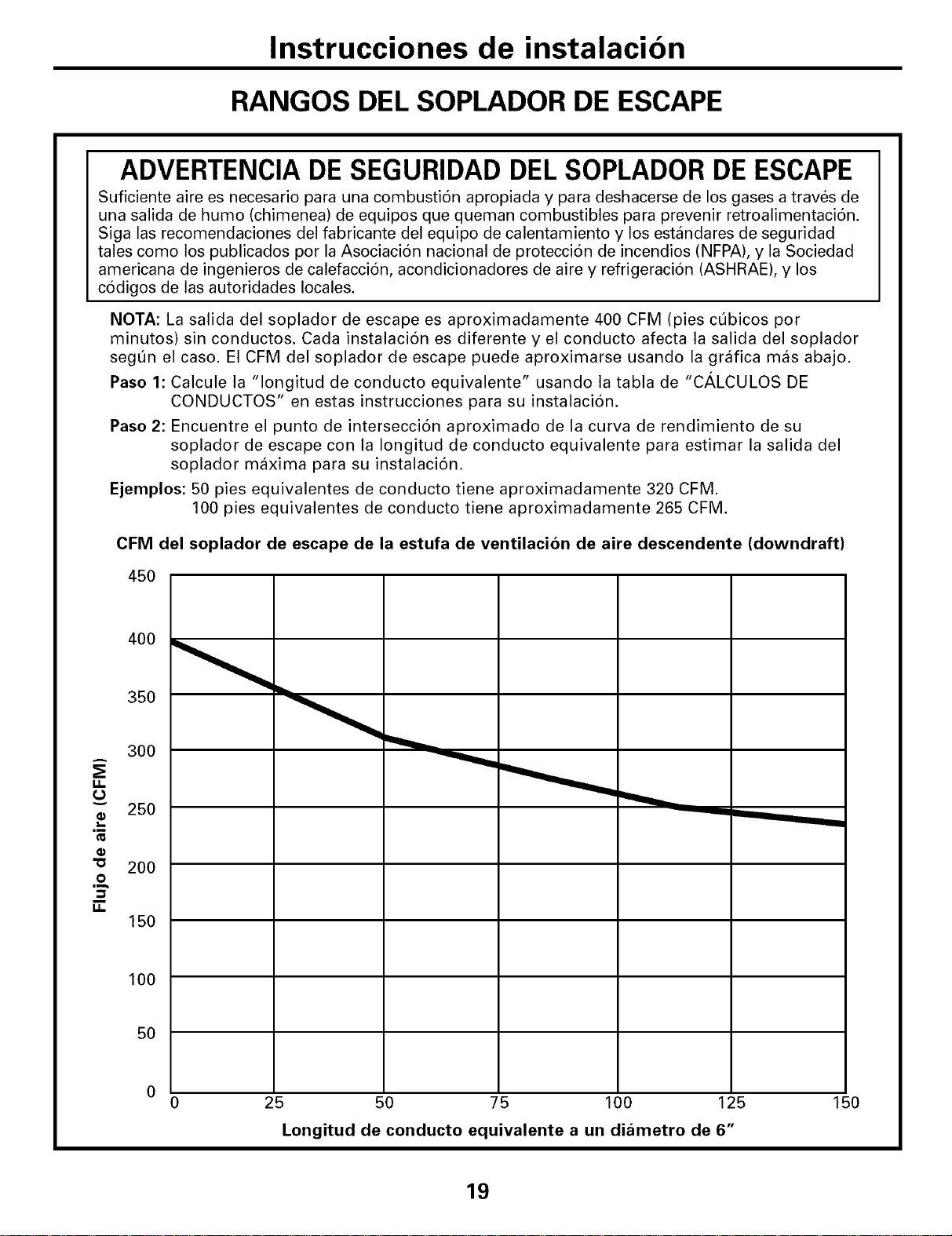
Instrucciones de instalacion
RANGOS DEL SOPLADOR DE ESCAPE
ADVERTENCIA DE SEGURIDAD DEL SOPLADOR DE ESCAPE
Suficiente aire es necesario para una combustion apropiada y para deshacerse de los gases a traves de
una salida de humo (chimenea) de equipos que queman combustibles para prevenir retroalimentacion.
Siga las recomendaciones del fabricante del equipo de calentamiento y los estandares de seguridad
tales como los publicados pot la Asociacion nacional de proteccion de incendios (NFPA), y la Sociedad
americana de ingenieros de calefaccion, acondicionadores de aire y refrigeraci6n (ASHRAE), y los
codigos de las autoridades locales.
NOTA: La salida del soplador de escape es aproximadamente 400 CFM (pies cQbicos por
minutos) sin conductos. Cada instalaci6n es diferente y el conducto afecta la salida del soplador
segQn el caso. El CFM del soplador de escape puede aproximarse usando la grMica mas abajo.
Paso 1: Calcule la "longitud de conducto equivalente" usando la tabla de "C_,LCULOS DE
CONDUCTOS" en estas instrucciones para su instalacion.
Paso 2: Encuentre el punto de interseccion aproximado de la curva de rendimiento de su
soplador de escape con la Iongitud de conducto equivalente para estimar la salida del
soplador maxima para su instalacion.
Ejemplos: 50 pies equivalentes de conducto tiene aproximadamente 320 CFM.
100 pies equivalentes de conducto tiene aproximadamente 265 CFM.
CFM del soplador de escape de la estufa de ventilacion de aire descendente (downdraft)
45O
ii
v
Im
,m
O
ii
350
300
25O
200
150
100
50
25 50 75 100 125
Longitud de conducto equivalente a un diametro de 6"
150
19
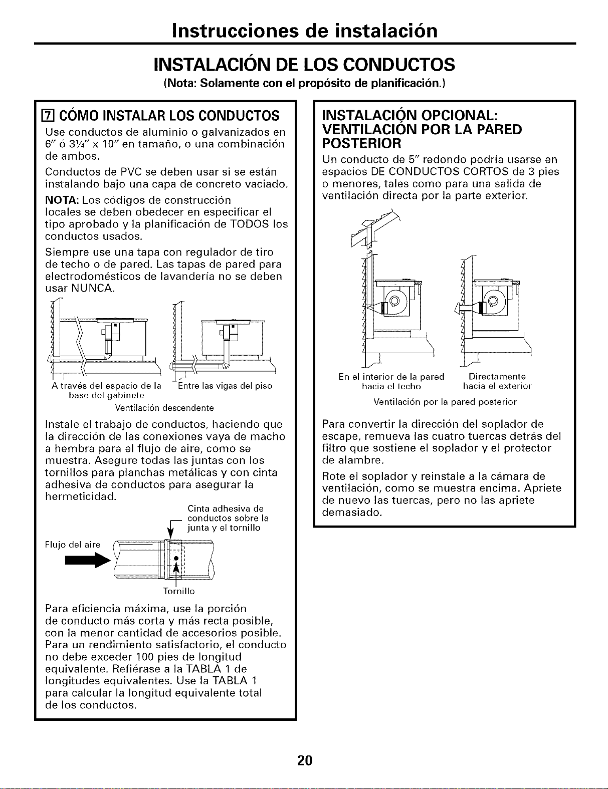
Instrucciones de instalacion
INSTALACION DE LOS CONDUCTOS
(Nota: Solamente con el proposito de planificacion.)
[] COMO INSTALAR LOS CONDUCTOS
Use conductos de aluminio o galvanizados en
6" 6 31/4" x 10" en tamaho, o una combinaci6n
de ambos.
Conductos de PVC se deben usar si se estan
instalando bajo una capa de concreto vaciado.
NOTA: Los c6digos de construcci6n
locales se deben obedecer en especificar el
tipo aprobado y la planificaci6n de TODOS los
conductos usados.
Siempre use una tapa con regulador de tiro
de techo o de pared. Las tapas de pared para
electrodomesticos de lavanderia no se deben
usar NUNCA.
Atraves del espacio de la
base del gabinete
Entre las vigas del piso
Ventilacion descendente
Instale el trabajo de conductos, haciendo que
la direcci6n de las conexiones vaya de macho
a hembra para el flujo de aire, como se
muestra. Asegure todas las juntas con los
tornillos para planchas metalicas y con cinta
adhesiva de conductos para asegurar la
hermeticidad.
Cinta adhesiva de
conductos sobre la
-- junta y el tornillo
Flujo__
Tornillo
Para eficiencia maxima, use la porci6n
de conducto mas corta y mas recta posible,
con la menor cantidad de accesorios posible.
Para un rendimiento satisfactorio, el conducto
no debe exceder 100 pies de Iongitud
equivalente. Refierase a la TABLA 1 de
longitudes equivalentes. Use la TABLA 1
para calcular la Iongitud equivalente total
de los conductos.
INSTALAClO."N OPCIONAL:
VENTILACION POR LA PARED
POSTERIOR
Un conducto de 5" redondo podria usarse en
espacios DE CONDUCTOS CORTOS de 3 pies
o menores, tales como para una salida de
ventilaci6n directa por la parte exterior.
En el interior de la pared
hacia el techo
Directa mente
hacia el exterior
Ventilacion por la pared posterior
Para convertir la direcci6n del soplador de
escape, remueva las cuatro tuercas detras del
filtro que sostiene el soplador y el protector
de alambre.
Rote el soplador y reinstale a la camara de
ventilaci6n, como se muestra encima. Apriete
de nuevo las tuercas, pero no las apriete
demasiado.
20
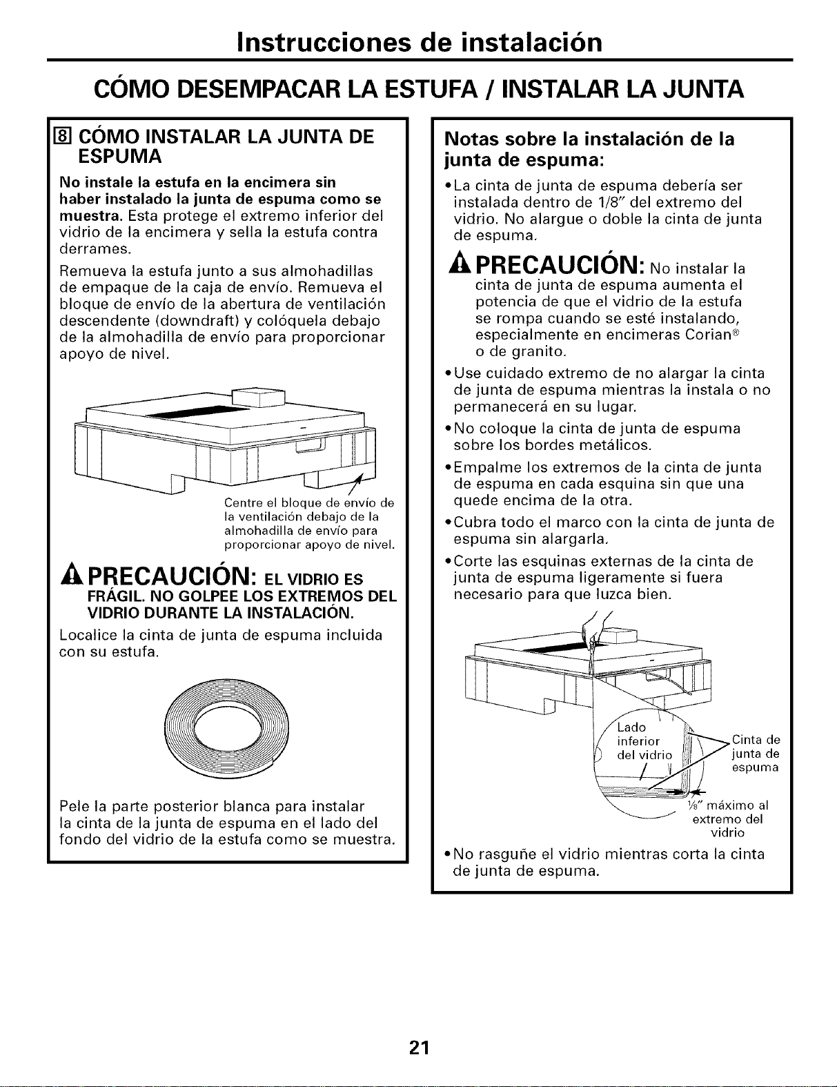
Instrucciones de instalacion
COIVIODESEMPACARLA ESTUFA / INSTALAR LA JUNTA
[] COIVIO INSTALAR LA JUNTA DE
ESPUMA
No instale la estufa en la encimera sin
haber instalado la junta de espuma como se
muestra. Esta protege el extremo inferior del
vidrio de la encimera y sella la estufa contra
derrames.
Remueva la estufa junto a sus almohadillas
de empaque de la caja de env{o. Remueva el
bloque de env{o de la abertura de ventilaci6n
descendente (downdraft) y col6quela debajo
de la almohadilla de envio para proporcionar
apoyo de nivel.
Centre el bloque de envio de
la ventilacion debajo de la
almohadilla de envio para
proporcionar apoyo de nivel.
f
--&PRECAUCION: EL VlDRIO ES
FRAGIL. NO GOLPEE LOS EXTREMOS DEL
VlDRIO DURANTE LA INSTALACION.
Localice la cinta de junta de espuma incluida
con su estufa.
Pele la parte posterior blanca para instalar
la cinta de la junta de espuma en el lado del
fondo del vidrio de la estufa como se muestra.
Notas sobre la instalacion de la
junta de espuma:
*La cinta de junta de espuma deber{a ser
instalada dentro de 1/8" del extremo del
vidrio. No alargue o doble la cinta de junta
de espuma.
PRECAUCION: Noinstalarla
cinta de junta de espuma aumenta el
potencia de que el vidrio de la estufa
se rompa cuando se este instalando,
especialmente en encimeras Corian ®
o de granito.
,Use cuidado extremo de no alargar la cinta
de junta de espuma mientras la instala o no
permanecera en su lugar.
*No coloque la cinta de junta de espuma
sobre los bordes metalicos.
*Empalme los extremos de la cinta de junta
de espuma en cada esquina sin que una
quede encima de la otra.
*Cubra todo el marco con la cinta de junta de
espuma sin alargarla.
,Corte las esquinas externas de la cinta de
junta de espuma ligeramente si fuera
necesario para que luzca bien.
\ Cinta de
junta de
" / _ _l espuma
............. _ll! _reaXiom_e_I
vidrio
,No rasgur_e el vidrio mientras corta la cinta
de junta de espuma.
21
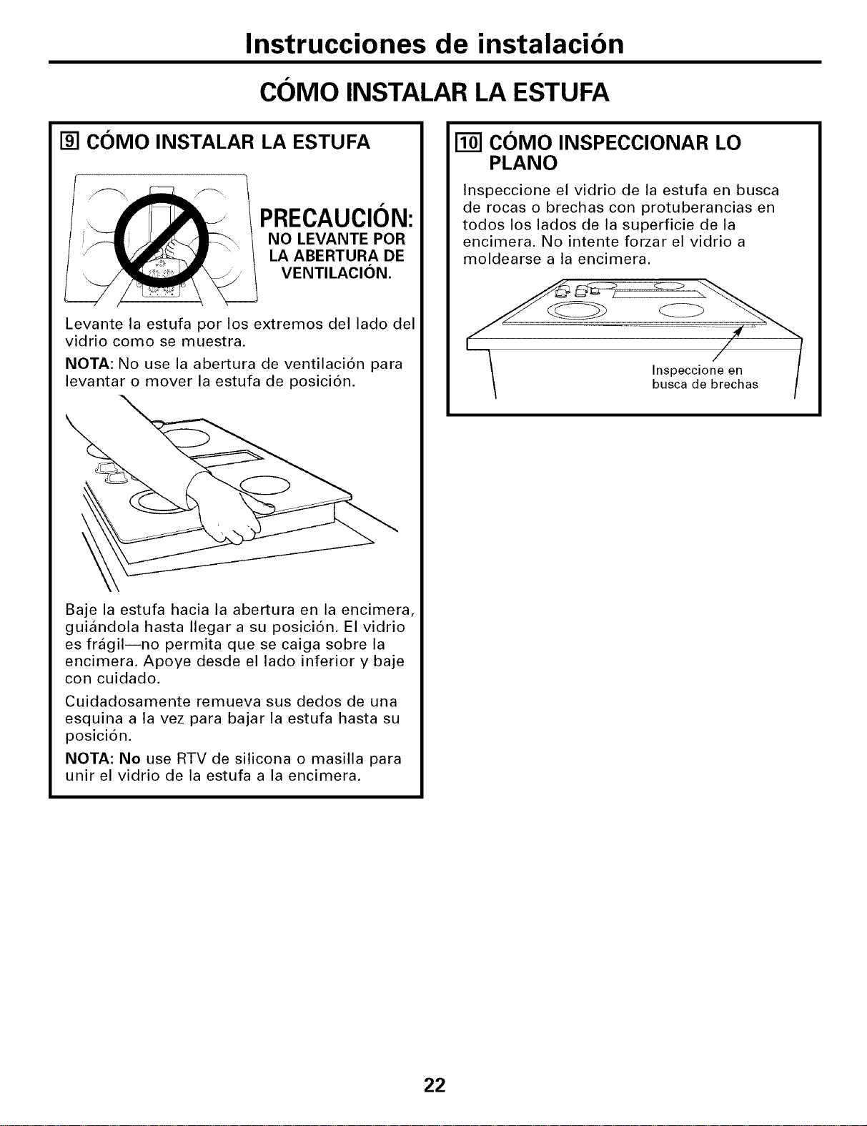
Instrucciones de instalacion
COMO INSTALAR LA ESTUFA
[] COMO INSTALAR LA ESTUFA
PRECAUCION:
NO LEVANTE POR
LA ABERTURA DE
VENTILACION.
Levante la estufa por los extremos del lado del
vidrio como se muestra.
NOTA: No use la abertura de ventilaci6n para
levantar o mover la estufa de posici6n.
Baje la estufa hacia la abertura en la encimera,
guiandola hasta Ilegar a su posici6n. El vidrio
es fragilJnO permita que se caiga sobre la
encimera. Apoye desde el lado inferior y baje
con cuidado.
Cuidadosamente remueva sus dedos de una
esquina a la vez para bajar la estufa hasta su
posici6n.
NOTA: No use RTV de silicona o masilla para
unir el vidrio de la estufa a la encimera.
[] COMO INSPECCIONAR LO
PLANO
Inspeccione el vidrio de la estufa en busca
de rocas o brechas con protuberancias en
todos los lados de la superficie de la
encimera. No intente forzar el vidrio a
moldearse a la encimera.
Inspeccione en
busca de brechas
22
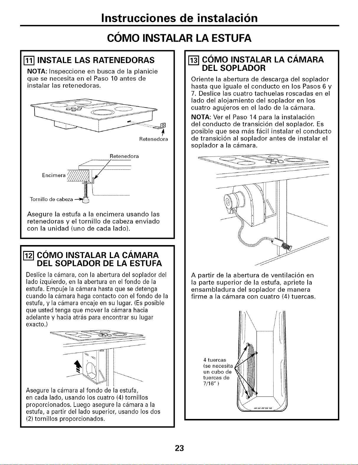
Instrucciones de instalacion
COMO INSTALAR LA ESTUFA
I_1 INSTALE LAS RATENEDORAS
NOTA: Inspeccione en busca de la planicie
que se necesita en el Paso 10 antes de
instalar las retenedoras.
Retenedora
Retenedora
Encimera _--
Tornillo de cabeza
Asegure la estufa a la encimera usando las
retenedoras y el tornillo de cabeza enviado
con la unidad (uno de cada lado).
I_1 COMO INSTALAR LA CAMARA
DEL SOPLADOR DE LA ESTUFA
Deslice la camara, con la abertura del soplador del
lado izquierdo, en la abertura en el fondo de la
estufa. Empuje la camara hasta que se detenga
cuando la camara haga contacto con el fondo de la
estufa, y la camara encaje en su lugar. (Es posible
que usted tenga que mover la camara hacia
adelante y hacia atras para encontrar su lugar
exacto.)
Asegure la camara al fondo de la estufa,
en cada lado, usando los cuatro (4) tornillos
proporcionados. Luego asegure la camara a la
estufa, a partir del lado superior, usando los dos
(2) tornillos proporcionados.
COMO INSTALAR LA CAMARA
DEL SOPLADOR
Oriente la abertura de descarga del soplador
hasta que iguale el conducto en los Pasos 6 y
7. Deslice las cuatro tachuelas roscadas en el
lado del alojamiento del soplador en los
cuatro agujeros en el lado de la camara.
NOTA: Ver el Paso 14 para la instalaci6n
del conducto de transici6n del soplador. Es
posible que sea mas facil instalar el conducto
de transici6n al soplador antes de instalar el
soplador a la camara.
A partir de la abertura de ventilaci6n en
la parte superior de la estufa, apriete la
ensambladura del soplador de manera
firme a la camara con cuatro (4) tuercas.
4 tuercas
(se necesita
un cubo de
tuercas de
7/16" )
23
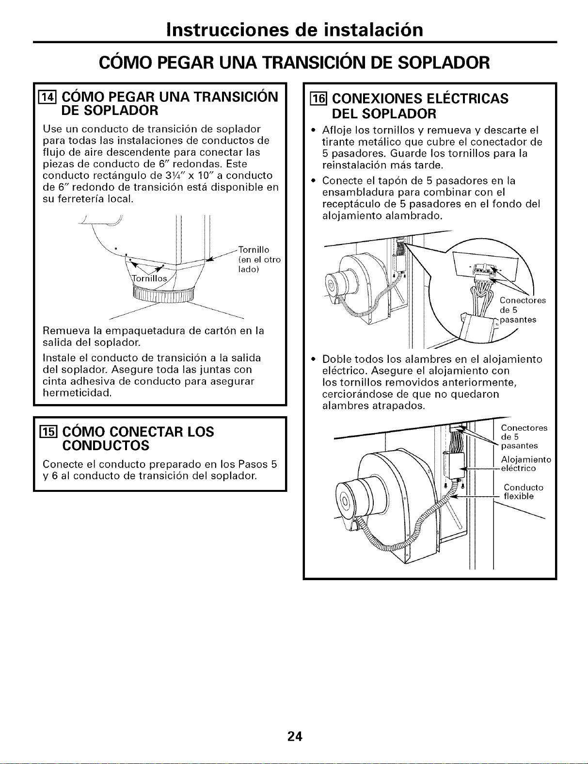
Instrucciones de instalacion
COMO PEGARUNA TRANSICION DE SOPLADOR
COMO PEGAR UNA TRANSICION
DE SOPLADOR
Use un conducto de transici6n de soplador
para todas las instalaciones de conductos de
flujo de aire descendente para conectar las
piezas de conducto de 6" redondas. Este
conducto rectangulo de 31/4" x 10" a conducto
de 6" redondo de transici6n esta disponible en
su ferreteria local.
Tornillo
c_o_lotro
Remueva la empaquetadura de cart6n en la
salida del soplador.
Instale el conducto de transici6n a la salida
del soplador. Asegure toda las juntas con
cinta adhesiva de conducto para asegurar
hermeticidad.
COMO CONECTAR LOS
CONDUCTOS
Conecte el conducto preparado en los Pasos 5
y 6 al conducto de transici6n del soplador.
CONEXIONES ELI_CTRICAS
DEL SOPLADOR
* Afloje los tornillos y remueva y descarte el
tirante metalico que cubre el conectador de
5 pasadores. Guarde los tornillos para la
reinstalaci6n mas tarde.
• Conecte el tap6n de 5 pasadores en la
ensambladura para combinar con el
receptaculo de 5 pasadores en el fondo del
alojamiento alambrado.
Conectores
de 5
,pasantes
Doble todos los alambres en el alojamiento
electrico. Asegure el alojamiento con
los tornillos removidos anteriormente,
cerciorandose de que no quedaron
alambres atrapados.
Conectores
de5
pasantes
Alojamiento
-electrico
Conducto
flexible
24
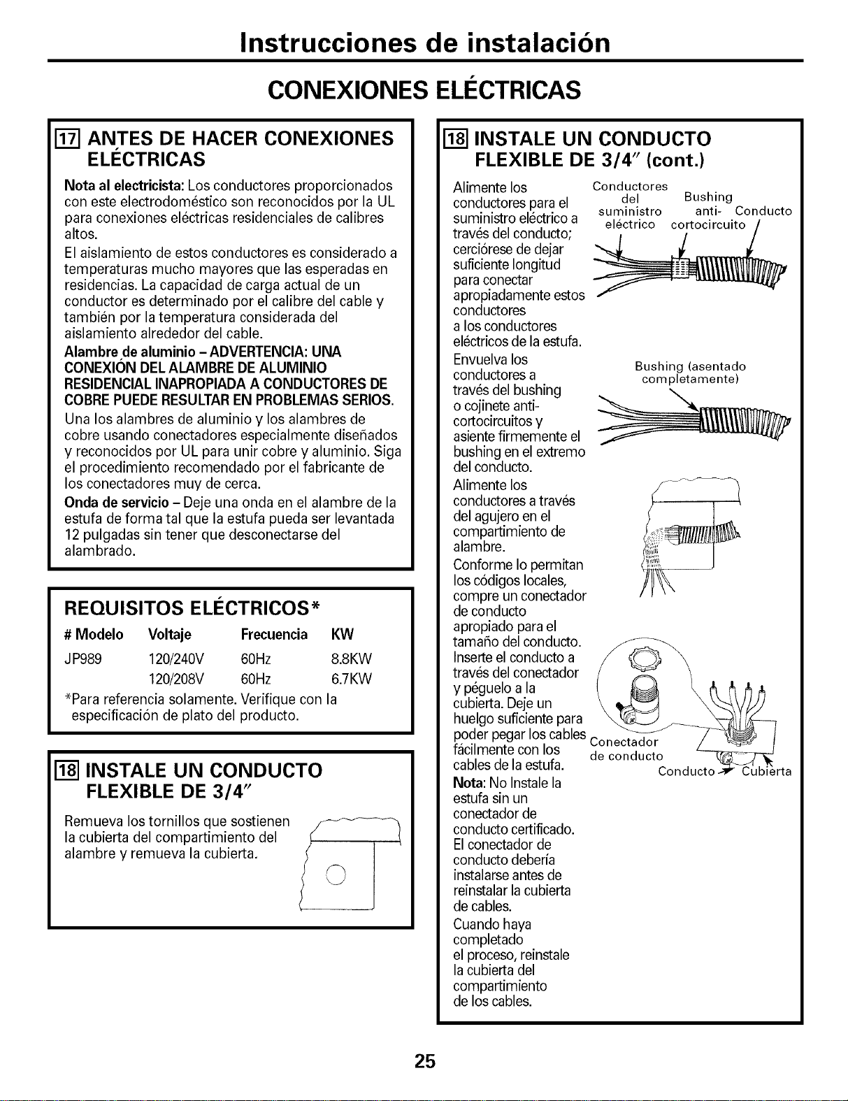
Instrucciones de instalacion
CONEXIONES ELI CTRICAS
[] ANTES DE HACER CONEXIONES
ELECTRICAS
Nota al electricista: Los conductores proporcionados
con este electrodomestico son reconocidos por la UL
para conexiones electricas residenciales de calibres
altos.
El aislamiento de estos conductores es considerado a
temperaturas mucho mayores que las esperadas en
residencias. La capacidad de carga actual de un
conductor es determinado per el calibre del cable y
tambien per la temperatura considerada del
aislamiento alrededor del cable.
Alambre de aluminio - ADVERTENCIA: UNA
CONEXION DEL ALAMBRE DE ALUMINIO
RESIDENCIAL INAPROPIADA A CONDUCTORES DE
COBRE PUEDE RESULTAR EN PROBLEMAS SERIOS.
Una los alambres de aluminio y los alambres de
cobre usando conectadores especialmente diseflados
y reconocidos per UL para unir cobre y aluminio. Siga
el procedimiento recomendado por el fabricante de
los conectadores muy de cerca.
Onda de servicio - Deje una onda en el alambre de la
estufa de forma tal que la estufa pueda ser levantada
12 pulgadas sin tener que desconectarse del
alambrado.
REQUISITOS ELI=CTRICOS*
# Modelo Voltaje Frecuencia
JP989 120/240V 60Hz
120/208V 60Hz
*Para referencia solamente. Verifique con la
especificacion de plato del producto.
KW
8.8KW
6.7KW
[] INSTALE UN CONDUCTO
FLEXIBLE DE 3/4"
Remueva los tornillos que sostienen
la cubierta del compartimiento del
alambre y remueva la cubierta.
[] INSTALE UN CONDUCTO
FLEXIBLE DE 3/4" (cont.)
Alimente los
conductores para el
suministro electrico a
traves del conducto;
cerciorese de dejar
suficiente Iongitud
para conectar
apropiadamente estos
conductores
a los conductores
electricos de la estufa.
Envuelva los
conductores a
traves del bushing
o cojinete anti-
cortocircuitos y
asiente firmemente el
bushing en el extremo
del conducto.
Alimente los
conductores a traves
del agujero en el
compartimiento de
alambre.
Conforme Io permitan
los codigos locales,
compre un conectador
de conducto
apropiado para el
tamaflo del conducto.
Inserte el conducto a
traves del conectador
y peguelo a la
cubierta. Deje un
huelgo suficiente para
poder pegar los cables
facilmente con los
cables de la estufa.
Nota: No Instale la
estufa sin un
conectador de
conducto certificado.
El conectador de
conducto deberfa
instalarse antes de
reinstalar la cubierta
de cables.
Cuando haya
completado
el proceso, reinstale
la cubierta del
compartimiento
de los cables.
Conductores
del Bushing
suministro anti- Conducto
electrico cortocircuito
Bushing (asentado
completamente)
Conectador
de conducto
rta
25
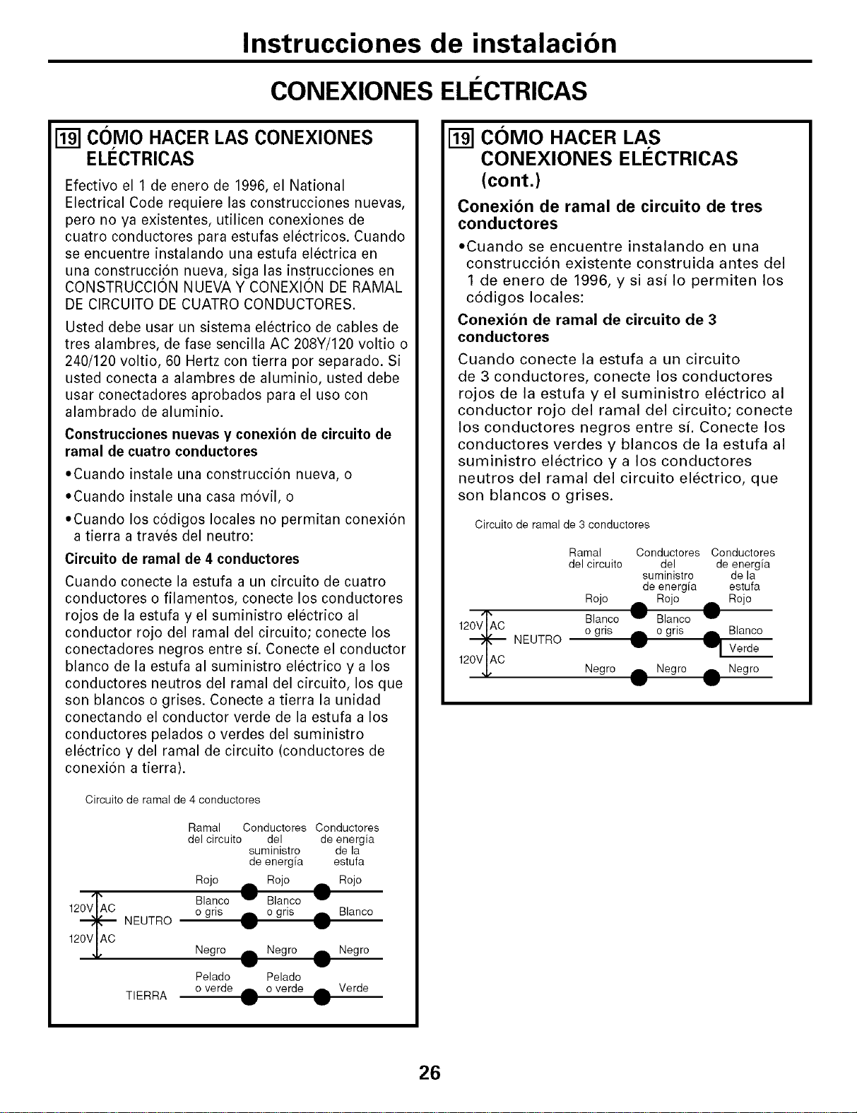
Instrucciones de instalacion
CONEXIONES ELI:I:CTRICAS
[] COMO HACER LAS CONEXIONES
EL¢CTRICAS
Efectivo el 1 de enero de 1996, el National
Electrical Code requiere las construcciones nuevas,
pero no ya existentes, utilicen conexiones de
cuatro conductores para estufas electricos. Cuando
se encuentre instalando una estufa electrica en
una construcci6n nueva, siga las instrucciones en
CONSTRUCClON NUEVA Y CONEXION DE RAMAL
DE CIRCUITO DE CUATRO CONDUCTORES.
Usted debe usar un sistema electrico de cables de
tres alambres, de fase sencilla AC 208Y/120 voltio o
240/120 voltio, 60 Hertz con tierra por separado. Si
usted conecta a alambres de aluminio, usted debe
usar conectadores aprobados para el uso con
alambrado de aluminio.
Construcciones nuevas y conexion de circuito de
ramal de cuatro conductores
• Cuando instale una construccion nueva, o
• Cuando instale una casa movil, o
• Cuando los codigos locales no permitan conexion
a tierra a traves del neutro:
Circuito de ramal de 4 conductores
Cuando conecte la estufa a un circuito de cuatro
conductores o filamentos, conecte los conductores
rojos de la estufa y el suministro electrico al
conductor rojo del ramal del circuito; conecte los
conectadores negros entre si. Conecte el conductor
blanco de la estufa al suministro electrico y a los
conductores neutros del ramal del circuito, los que
son blancos o grises. Conecte a tierra la unidad
conectando el conductor verde de la estufa a los
conductores pelados o verdes del suministro
electrico y del ramal de circuito (conductores de
conexion a tierra).
Circuito de ramal de 4 conductores
120VIAC
NEUTRO
Ramal Conductores Conductores
del circuito del de energia
suministro de la
de energia estufa
Rojo A Rojo rib, Rojo
Blanco _ Blanco IW'
o gris _b, o gris dL Blanco
TIERRA
Negro A Negro rib, Negro
Pelado Pelado
o verde dlk o verde rill Verde
COMO HACER LAS
CONEXIONES ELI CTRICAS
(cont.)
Conexion de ramal de circuito de tres
conductores
',Cuando se encuentre instalando en una
construcci6n existente construida antes del
1 de enero de 1996, y si asi Io permiten los
c6digos locales:
Conexion de ramal de circuito de 3
conductores
Cuando conecte la estufa a un circuito
de 3 conductores, conecte los conductores
rojos de la estufa y el suministro electrico al
conductor rojo del ramal del circuito; conecte
los conductores negros entre si. Conecte los
conductores verdes y blancos de la estufa al
suministro electrico y a los conductores
neutros del ramal del circuito electrico, que
son blancos o grises.
Circuito de ramal de 3 conductores
120V LAC
NEUTRO
Ramal Conductores Conductores
del circuito del de energia
suministro de la
de energfa estufa
Rojo rib, Rojo _ Rojo
Blanco I_' Blanco
o gris _ o gris A Blanco
IIF 11. Verde
Negro rib, Negro Negro
.. @
26
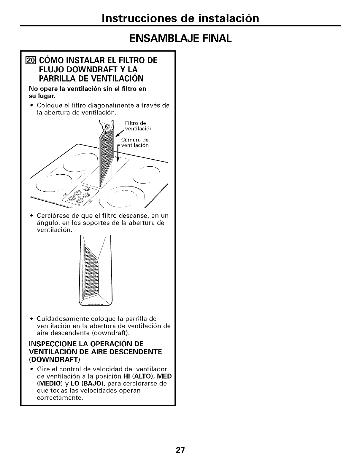
Instrucciones de instalacion
ENSAMBLAJE FINAL
[] C()MO INSTALAR EL FILTRO DE
FLUJO DOWNDRAFT Y LA
PARRILLA DE VENTILACI()N
No opere la ventilacion sin el filtro en
su lugar.
• Coloque el filtro diagonalmente a traves de
la abertura de ventilacion.
Filtro de
ventilacion
Camara de
.ventilacion
k _ .........
Cerci6rese de que el filtro descanse, en un
angulo, en los soportes de la abertura de
ventilaci6n.
* Cuidadosamente coloque la parrilla de
ventilaci6n en la abertura de ventilaci6n de
aire descendente (downdraft).
INSPECCIONE LA OPERACION DE
VENTILACION DE AIRE DESCENDENTE
(DOWNDRAFT)
• Gire el control de velocidad del ventilador
de ventilaci6n a la posici6n HI (ALTO), MED
(MEDIO) y LO (BAJO), para cerciorarse de
que todas las velocidades operan
correctamente.
27
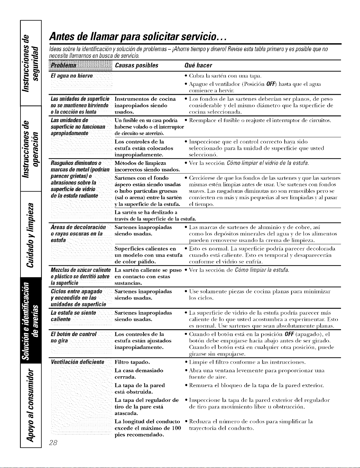
Antesde Ilamarpara solicitar servicio...
Ideas sobre la identificaciOn y soluciSn de problemas - iAhorre fiempo y diner#. Revise esta tabla primero yes posible que no
necesiteIlamarnosenbuscadeservicio.
_ i: Causas posibles
Elagua nohierve
Que hacer
• Cubra la sart_n con tma mpa.
• Apague el ventilador (Posicidn OFF) hasta que el agua
coil/ience a hervii:
Las unidades de superficie ]nstrumentos de cocina • Los fl)ndos de las sartenes (leberian ser pianos, (le peso
nosemantienenhirviendo inapropiados siendo considerable v del mismo difimetro que 1:1superiicie de
o/a cocciOo e$ /eota usados, cocina selecci'onada.
Las nnidades de Un fusible en su casa podrla • Reeuq)lace el fl/sible o reaj uste el interrupt()r de circuit()s.
$nperlicie no fnncionan haberse volado o el interruptor
apropiadamente de circuito se aterriz6.
Los controles de la • /nspeccione que el control (-orrecto hava sido
estufa estfiJ_ colocados seleccionado para 1;I unidad de superticie que usted
inapropiadamente, seleccion6.
RasguOos diminutos o M6todos de lhnpieza • Vet 1;i seccidn Cdmo limpiar el vidrio de la estufa.
marcas de metal (podrian hzcorrectos siendo usados.
parecergrietas) o Sartenes con el rondo • (_ercidrese de que los fimdos de las sartenes y que las sartenes
abrasiones sobre la fispero estml siendo usadas mismas est_n limpias ;llltes de usm: Use SilYtelleS con ti)ndos
supedicie de vidrio o hubo particulas gruesas stlaves. Las rasgaduras diminutas no son removibles pero se
de la estufa radiante (saJ o arena) entre la sart6n convierten ell mils v mils pequefias :11set limpiadas y ;11pasar
y la superficie de la estufa, el fiempo.
La sart6n se ha deslizado a
trav6s de la superficie de la estufa.
Areas de decoloracion Sartenes inapropiadas • l,as marcas de sartenes de ahuninio v de cobre, asi
o rayas oscnras en la siendo usadas, como los depdsitos minerales del agua y de los alimentos
estufa pueden removerse usando 1:1crema de limpieza.
Superficies calientes en • Esto es normal. La superficie podria parecer decolorada
un modelo con tma estufa cuando estfi caliente. Esto es temporal y desaparecerfin
de color pfilido, conforme el vidrio se enfl'ia.
Mezclas de az#car caliente La sart6n caliente se puso • Vet 1:1seccidn de Cdmo/impiar/a estufa.
o plastico se derriti6 sobre en contacto COil estas
la superficie sustancias.
Ciclos entre apagado Sartenes inapropiadas • Use solmnente piezas de cocina planas para minimizar
y encendido en las siendo usadas, los ciclos.
unidades de supetticie
La estufa se siente Sartenes inapropiadas • La superficie de vidrio de la estulh podria parecer mils
caliente siendo usadas, caliente de lo que usted acostumbra a experiulentar. Esto
es noYIl/;ll. Lrse Sal'tenes qt/e Se_lll _lbsoll/t;lll/en[e planas.
E1bonn de control Los controles de la • ()rondo el botdn esth ell 1:1posicidn OFF(apagado), el
no gira estufa estfiJ:l ajustados botdn debe empujarse hacia abajo antes de set girado.
inapropiadamente. (_uando el botdn estfi ell cuahluier otra posicidn, puede
girarse Sill empt!jarse.
Ventilacion deficiente Fihro tapado. • IJmpie el filtro conforu/e alas instrucciones.
La casa demasiado • Abra t/ll;I vent;in;i levelnente 11_11";i})YopoYcion;IY t/ll_l
cerrada, fiwnte de aire.
La tapa de la pared
estfi obstruida.
• ]lemueva el bloqueo de la tapa de la pared exterior.
La tapa del regulador de • lnspeccione la tapa de la pared exterior del regulador
tiro de la pare estfi de tiro para ino'Alniento libre u obstruccidn.
atascada.
La longitud del conducto
excede el mfiximo de 100
pies recomendado.
28
• Reduzca el nfimero de co(los para simplificar la
traxectoria del condtlcto.
Neta$.
29
crJ _
€_
N
we_
P_wJ
r,fJ
m
m
Notas.
_r4
_r4
r.3
w
i
i
z_
Garantiade GEpara su estufade cubierta el#ctrico.
Todos los servicios de garantfa los proporcionan nuestros Centros
de ReparaciSn de F#brica o nuestros t#cnicos Customer Care®
autorizados. Para concertar una cita de reparaciSn, en ffnea,
24 horas al dfa, visftenos en www.GEAppfiances.com, o flame al
800.GE.CARES (800.432.2737).
Peque aqu[su recibo.
Se requiem facilitar prueba
de la fecha de compra original
para obtener un servicio
bajo la garantfa.
Una#o
A pardr de la fecha
de la compraoriginal
Cincoa#os
A par'drde la fecha
de la compraoriginal
GEreemplazarft:
Cualquierparte de la estufi_ de cubierta que riffle debido a defectos en los matefiales
o en la fid)ficad6n. Durante este a_o completo de garantia, GE tambi&n proportion;i, sin
costo alguno, toda la mano de obra y los sei'vicios internos para reemplazar partes def_'ctuosas.
Una estufa de vidrio de reemplazo si es que: la ruptura se debe atm golpe t_mfico; la
decoloraci(/n; o si el molde se desgastn,
Una unidad de superficie radiante si se quema.
Din'ante esta garantia adicional limitada de cuaffo anos, usted ser;i responsable de cualquier
labro o servicio en casa.
Viajes de servicio a su casa paxa mostrarle como
fmlciona el equipo.
Insta]aci6n, entrega o mmltenhniento hmpropriada.
Fa]lo del producto resttltaalte de modificaciones a]
producto o debido a uso hlcorrecto h_cluyendo no
proporcionar mm_te_fimiento razonable y necesario.
Dm-lo a la estufa de vidxio causado pot el uso de
limpiadores dJferentes alas cremas y almohadillas
recomendadas.
Dm-lo a h estufa de vidxio causado pot derrmnes
endttrecidos de materiales azucaxados o pot pkistico
derretido que no sem_ lhnpiados confonne alas
dJrecciones en el Mmmal del propietaxio.
Reemplazo de fusibles de la casa o reajuste del sistema
de circuitos.
Da6o al producto causado por accidentes, hlcendios,
hltmdaciones o actos de la naturaJeza de fuerza mayor.
Dafos hacidentaJes o consecuenciaJes causados por
defectos posibles con este apm'ato.
Dafos causados despu6s de la entrega.
Esta garant[a se extiende al comprador original y cualquier comprador posterior de pmductos comprados para
uso residencial dentro des Estados Unidos. En Alaska, la garant[a excluye el costo de env[o o las visitas de servicio
a su casa.
Algunos estados no permiten la exclusiSn o las limitaciones de dafios incidentales o consecuencbles. Esta garantfa
da derechos legales especificos, y usted podria tener otros derechos que variar#n de estado a estado. Para saber
cu#les son sus derechos legales, consulte a la oficina de asuntos del consumidor local o la oficina del Prucurador
(Attorney General) en su Iocalidad.
Garante: General Electric Company.Louisville, KY 40225
31
Apoyoal Consumidor.
P@/naWebdeGEAppl/ances www.GEAppliances.com
,_'Tiene algtma pregunta sol)re su electrodon/_stico? iPmebe la p;igina Wel) de GE Appliances 24 horas al
dfa, cualquier dfa del aflo! Para mayor conveniencia v servicio re;is r_ipi(lo, ya puede descargar los Manuales
de los Propietarios, pedir piezas o incluso hacer una dta en lfnea para que vengan a realizar una
reparacidn. Tambi_n puede "_sk Our Team of Experts"' (Preguntar a nuestro equipo de expertos)
sobre cualquier cuestidn y mucho re;is...
Soliciteunareparaci6n www.GEAppliances.com
E1 servicio de expertos (;E est;i a tan sdlo ml paso de su puerta, iEntre en lfnea _ solicite su reparaci6n
cuando le xenga bien 24 horas al dfa cualquier dfa del afio_ O llame al 800.(;E.(:ARES (800.432.2737)
durante horas n(mnales de oficina.
RealLifeDesignStudio(Estudiodedisefioparalavidareal)www.GEAppliances.com
GE at)ova el concepto de Disefio Univex_al--productos, servicios y ambientes que pueden usar gente de
todas las edades, tamafios y capacidades. Reconocemos la necesidad de diseflar para una gran gama de
habilidades y dificultades tisicas y mentales. Para mils detalles cobre las aplicaciones de GE Disefio Universal,
incluvendo ideas de disefio para la cocina para personas con discapacidades, mire nuestra pfigina 't.Veb hov
mismo. Para personas con dificultades audifiw_s, Ire'or de llamar al 800.TDD.GEAC (800.833.4322).
Garantfasampliadas www.GEAppliances.com
COral)re una ,garantfa ampliada ) obtenga detalles sol)re descuentos especiales disponil)les mientras su
garant_a estfi afin acfixa. Puede comprarla en l_nea en cualquier momento, o llamar al 800.626.2224
durante horas nommles de oficina. GE Consumer Home Services estarfi afin ahf cuan(lo su garantfa temfine.
Piezasyaccesorios _w. GEAppliances.com
Aquellos individuos con la calificaci6n necesaria para reparar sus propios electrodom_sticos pueden
pedir que se les manden las piezas o accesorios (lirectamenm a sus hogares (aceptamos las tmjetas
VISA, MasterCard y Discover). Haga su pedido en lfnea ho 5 24 horas cada dfa o llamar pot mkqbno
al 800.626.2002 durante horas nommles de olicina.
Lasinstruccionesdescritasenestemanualcubrenlospmcedimientosa seguirpercualquierusuario.Cualquier
otrareparaci6ndeberia,per reglageneral,referirsea personalcalificadoautorizado.Debeejercerse precauci6n
ya quelasreparacionesincorrectaspueden causarcondicionesdefuncionamientoinseguras.
P6ngaseencontacto connosotros www.GEAppliances.com
Si no est_i satisfecho con el servicio que recil)e de (;E, pdngase en conta('to con nosotros en nuestra p;igina
_'eb indicando todos los detalles asf como su nfimero de tel_flmo o escrfl)anos a:
General Manage_; Customer Relations
GE Appliances, Appliance Park
I,ouis\ille, KY 40225
Registre sue/ectrodom_stico www.GEAppliances.com
iRegistre su nuevo electrodom6stico ell lfilea-----cuaaldo usted prefiera! E1 registrar Stl prodtlcto a tielllpo le
proporcionar_i, si smgiera la necesidad, tma mejor comunicaci6n y un servicio mils r_ipido bajo los t&minos
de su garantfa. Talnbi_n puede enviar su taijeta de registro pre-inlpresa title se incluve en el inaterial
de embalaje.
Impreso on los E-U

