Loading ...
Loading ...
Loading ...
Your Operator's Manual has been developed to help
you assemble the unit and to understand its safe opera-
tion It is important that you read your manual com-
pletely to become familiar with the unit before you begin
assembly,
1. READ YOUR OPERATOR'S MANUAL,
2_ No tools are required to assemble your blower,
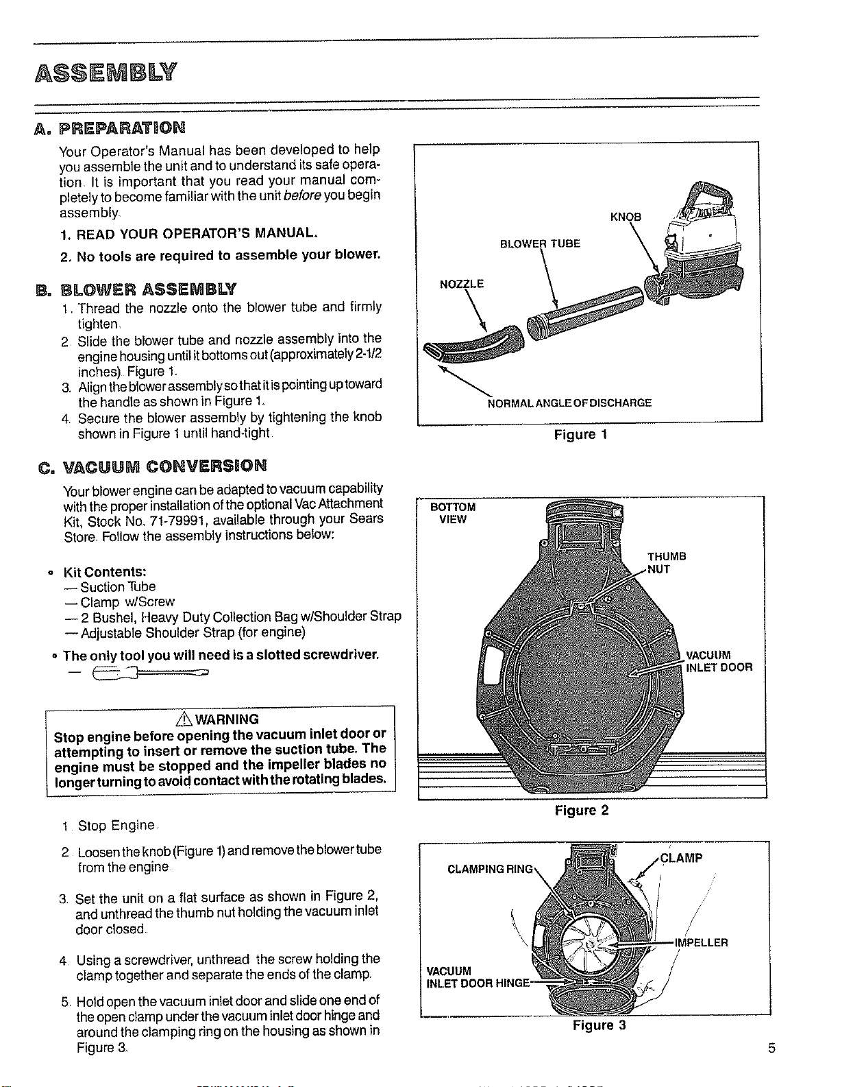
B. BLOWER ASSEMBLY
1 Thread the nozzle onto the blower tube and firmly
tighten,
2 Slide the blower tube and nozzle assembly into the
engine housing until itbottoms out (approximately 2-t/2
inches) Figure 1_
3, Align theblowerassembly sothat itispointing uptoward
the handle as shown in Figure 1.
4, Secure the blower assembly by tightening the knob
shown in Figure 1 until hand-tight
Co VACUU_ COHVERSION
Your blower engine can be adapted tovacuum capability
with the properinstallation of the optional VacAttachment
Kit, Stock No_71-79991. available through your Sears
Store, Follow the assembly instructions below:
o Kit Contents:
-- Suction Tube
-- Clamp w/Screw
-- 2 Bushel. Heavy Duty Collection Bag w/Shoulder Strap
--Adjustable Shoulder Strap (for engine)
o The only tool you will need is a slotted screwdriver.
_WARNING
Stop engine before opening the vacuum inlet door or
attempting to insert or remove the suction tube. The
engine must be stopped and the impeller blades no
longer turning to avoidcontact with the rotating blades.
1 Stop Engine
2 Loosen the knob (Figure 1)and remove the blowertube
from the engine
3 Set the unit on a flat surface as shown in Figure 2,
and unthread the thumb nut holding the vacuum inlet
door closed
4 Using a screwdriver, unthread the screw holding the
clamp together and separate the ends of the clamp,
5 Hold open the vacuum inlet door and slideone end of
the open clamp under the vacuum inlet door hingeand
around the clamping ring on the housing as shown in
Figure 3.
NOZZLE
\
BLOWER TUBE
KNOB
NORMALANGLEOFDISCHARGE
Figure 1
BOTTOM
VIEW
Figure 2
CLAMPING RING_
VACUUM
Figure 3
THUMB
_NUT
VACUUM
INLET DOOR
//
IMPELLER
Loading ...
Loading ...
Loading ...