

Owner's Manual
ICRRFTSMIIN°I
17.5 HP, 42" Mower
Electric Start
Automatic Transmission
Model No.
917.273383
This product has a mowemission engine which operates
differentmy from previously buimt engines. Before you start the
engine, read and understand this Owner's Manuak
Read and follow aH Safety
Rules and Instructions before
operating this equipment.
For answers to your questions
about this product, Call:
1-800°659°5917
Sears Craftsman Help Line
5 am = 5 pm, Men =Sat
Sears, Roebuck and Co., Hoffman Estates, IL 60179 U.S.A
Visit our Craftsman website:www.sears.com/craftsman
Warranty................................................2
Safety Rules..........................................3
ProductSpecifications...........................6
AssemblyPre-Operation........................8
Operation.............................................11
Maintenance.......................................18
MaintenanceSchedule........................18
Serviceand Adjustments.....................23
Storage................................................29
Troubleshooting...................................30
Repair Parts.........................................34
Sears Service........................Back Cover
LIMITEDWARRANTYON CRAFTSMANRIDINGEQUIPMENT
Fortwo (2) years from the date of purchase,if this CraftsmanRiding Equipmentis
maintained,lubricatedand tuned up accordingto the instructionsin the owner'smanual,
Sears will repairor replacefree of charge any parts that are found to be defectivein
materialor workmanshipaccordingto the guidelinesof coveragelistedbelow.Searswill
also providefree laborfor these applicablewarrantedpartsfor the two full years. During
the first 30 days of purchase,there will be no chargesto servicethe productat your
homefor issuescoveredbythis warranty.(Seeexclusionsbelow). Foryour conve-
nience, IN HOMEwarrantyservice will still be availableafterthe first 30 days of pur-
chase, buta trip charge will apply.Thischargewill be waived if the Craftsmanproductis
droppedoff at an authorizedSears location.Forthe nearestauthorizedSears location,
pleasecall 1-800-4-MY-HOME@.This warrantyappliesonly while this productis within
the UnitedStates.
This Warrantydoes not cover:
Expendableitemswhichbecomeworn during normaluse, includingbut not limitedto
blades,spark plugs,air cleaners, belts, and oil filters.
StandardMaintenanceServicing,oil changes, or tune-ups
Tire replacementor repair caused by puncturesfrom outsideobjects,such as nails,
thorns,stumps,or glass.
Repairsnecessarybecauseof operatorabuse, includingbut not limitedto, damage
causedby towing objects beyondthe capabilityof the riding equipment,impacting
objectsthat bendthe frameor crankshaft,or over-speedingthe engine.
Repairsnecessarybecauseof operatornegligence,includingbut not limitedto, elec-
trical and mechanicaldamagecausedby improperstorage,failureto use the proper
gradeand amount of engine oil, failureto keepthe deckclear of flammabledebris,
or failure to maintainthe equipmentaccordingto the instructionscontainedin the
owner'smanual.
Engine(fuel system)cleaning or repairs caused by fuel determinedto be contami-
natedor oxidized(stale). In general,fuel should be used within30 days of its pur-
chase date.
Normaldeteriorationand wear of the exteriorfinishes,or productlabel replacement.
Ridingequipmentused for commercialor rental purposes.
LIMITEDWARRANTYON BATTERY
For ninety (90) daysfrom date of purchase,if any battery included with this ridingequip-
ment provesdefectivein material or workmanshipand our testing determinesthe battery
will not hold a charge,Sears will replacethe batteryat no charge. Duringthe first 30
days of purchase,there will be no chargesto replacethe batteryat your HOME. After
the first 30 days, for your convenience,IN-HOMEwarrantyservice will still be avail-
ablebut a trip chargewill apply. Thischarge will be waived if the Craftsmanproductis
droppedoff at an authorizedSears location.Forthe nearestauthorizedSears location,
pleaseca[[ 1-800-4-MY-HOME@.
This batterywarrantyapplies only while this productis within the United States.
This warrantygivesyou specificlegal rights,and you mayalso haveother rights,which
vary,from state to state.
Sears,Roebuckand Co.,Dept.817WA,HoffmanEstates,IL 60179
2
JiVIPORTANT: This cutting machine is capable of amputating hands and feet and throw-
ing objects. Failure to observe the following safety instructions could result in serious
injury or death.
,_WARNJNG: In order to prevent ac-
cidental starting when setting up, trans-
porting, adjusting or making repairs,
always disconnect spark plug wire and
place wire where it cannot contact spark
plug.
_U_WARNING: Do not coast down a hill in
neutral, you may lose control of the tractor.
_f_,WARNING: Tow only the attachments
that are recommended by and comply with
specifications of the manufacturer of your
tractor. Use common sense when towing.
Operate only at the lowest possible speed
when on a slope. Too heavy of a load,
while on a slope, is dangerous. Tires can
lose traction with the ground and cause
you to lose control of your tractor.
,_WARNING: Engine exhaust, some of
its constituents, and certain vehicle com-
ponents contain or emit chemicals known
to the State of California to cause cancer
and birth defects or other reproductive
harm.
,_WARNING: Battery posts, terminals
and related accessories contain lead and
lead compounds, chemicals known to the
State of California to cause cancer and
birth defects or other reproductive harm.
Wash hands after handling.
L GENERAL OPERATION
* Read, understand, and follow all instruc-
tions in the manual and on the machine
before starting.
Only allow responsibJe adults, who are
familiar with the instructions, to operate
the machine.
, Clear the area of objects such as rocks,
toys, wire, etc., which could be picked
up and thrown by the blade.
Be sure the area is clear of other people
before mowing. Stop machine if anyone
enters the area.
Never carry passengers.
Do not mow in reverse unless abso-
lutely necessary. Always look down and
behind before and while backing.
Be aware of the mower discharge direc-
tion and do not point it at anyone. Do
not operate the mower without either
the entire grass catcher or the guard in
place.
Slow down before turning.
Never leave a running machine unat-
tended. Always turn off blades, set
parking brake, stop engine, and remove
keys before dismounting.
Turn off blades when not mowing.
Stop engine before removing grass
catcher or unclogging chute.
Mow only in daylight or good artificial
light.
Do not operate the machine while under
the influence of alcohol or drugs.
Watch for traffic when operating near or
crossing roadways.
Use extra care when loading or un-
loading the machine into a trailer or
truck.
Data indicates that operators, age 60
years and above, are involved in a large
percentage of riding mower-related in-
juries. These operators should evaluate
their ability to operate the riding mower
safely enough to protect themselves
and others from serious injury.
Keep machine free of grass, leaves or
other debris build=up which can touch
hot exhaust / engine parts and burn. Do
not allow the mower deck to plow leaves
or other debris which can cause build-
up to occur. Clean any oil or fuel
spillage before operating or storing the
machine. Allow machine to cool before
storage.
JL SLOPE OPERATION
Slopes are a major factor reJated to loss-
of-control and tipover accidents, which can
result in severe injury or death. AJl slopes
require extra caution. If you cannot back
up the slope or if you feel uneasy on it, do
not mow it.
3

DO:
Mow up and down slopes, not across.
Remove obstacles such as rocks, tree
limbs, etc.
Watch for holes, ruts, or bumps. Un-
even terrain could overturn the machine.
Taft grass can hide obstacles.
Use slow speed. Choose a low gear
so that you will not have to stop or shift
while on the slope.
Follow the manufacturer's recommend-
ations for wheel weights or counter-
weights to improve stability.
Use extra care with grass catchers or
other attachments. These can change
the stability of the machine.
Keep all movement on the slopes slow
and gradual Do not make sudden
changes in speed or direction.
Avoid starting or stopping on a slope. If
tires lose traction, disengage the blades
and proceed slowly straight down the
slope.
DO NOT:
o Do not turn on slopes unless neces-
sary, and then, turn slowly and gradually
downhill, if possible.
Do not mow near drop-offs, ditches,
or embankments. The mower could
suddenly turn over if a wheel is over
the edge of a cliff or ditch, or if an edge
caves in.
Do not mow on wet grass. Reduced
traction could cause sliding.
Do not try to stabilize the machine by
putting your foot on the ground.
Do not use grass catcher on steep
slopes.
ill. CHILDREN
Tragic accidents can occur if the operator
is not alert to the presence of children.
Children are often attracted to the ma-
chine and the mowing activity. Never as-
sume that children will remain where you
last saw them.
Keep children out of the mowing area
and under the watchful care of another
responsible adult.
Be alert and turn machine off if children
enter the area.
Before and when backing, look behind
and down for small children.
Never carry children. They may fall off
and be seriously injured or interfere with
safe machine operation.
Never allow children to operate the
machine.
Use extra care when approaching blind
corners, shrubs, trees, or other objects
that may obscure vision.
iV. SERVICE
Use extra care in handling gasoline and
other fuels. They are flammable and
vapors are explosive.
- Use only an approved container.
- Never remove gas cap or add fuel
with the engine running. Allow
engine to cool before refueling. Do
not smoke.
- Never refuel the machine indoors.
- Never store the machine or fuel
container inside where there is an
open flame, such as a water heater.
Never run a machine inside a closed
area.
Keep nuts and bolts, especially blade
attachment bolts, tight and keep equip-
ment in good condition.
Never tamper with safety devices.
Check their proper operation regularly.
Keep machine free of grass, leaves, or
other debris build-up. Clean oil or fuel
spillage. Allow machine to cool before
storing.
Stop and inspect the equipment if you
strike an object. Repair, if necessary,
before restarting.
Never make adjustments or repairs with
the engine running.
Grass catcher components are subject
to wear, damage, and deterioration,
which could expose moving parts or
allow objects to be thrown. Frequently
check components and replace with
manufacturer's recommended parts,
when necessary.
Mower blades are sharp and can cut.
Wrap the blade(s) or wear gloves, and
use extra caution when servicing them.
Check brake operation frequently. Ad-
just and service as required.
4

Be sure the area is clear of other people
before mowing. Stop machine if anyone
enters the area.
Never carry passengers or children
even with the blades off.
Do not mow in reverse unless abso-
lutely necessary. Always look down and
behind before and while backing.
Never carry children. They may fall off
and be seriously injured or interfere with
safe machine operation.
Keep children out of the mowing area
and under the watchful care of another
responsible adult.
Be alert and turn machine off if children
enter the area.
Before and when backing, look behind
and down for small children.
Mow up and down slopes (15 ° Max),
not across.
Remove obstacles such as rocks, tree
limbs, etc.
Watch for holes, ruts, or bumps. Uneven
terrain could overturn the machine. Tall
grass can hide obstacles.
Use slow speed. Choose a low gear
so that you will not have to stop or shift
while on the slope.
Avoid starting or stopping on a slope. If
tires lose traction, disengage the blades
and proceed slowly straight down the
slope.
If machine stops while going uphill,
disengage blades, shift into reverse and
back down slowly.
Do not turn on slopes unless necessary,
and then, turn slowly and gradually
downhill, if possible.
5
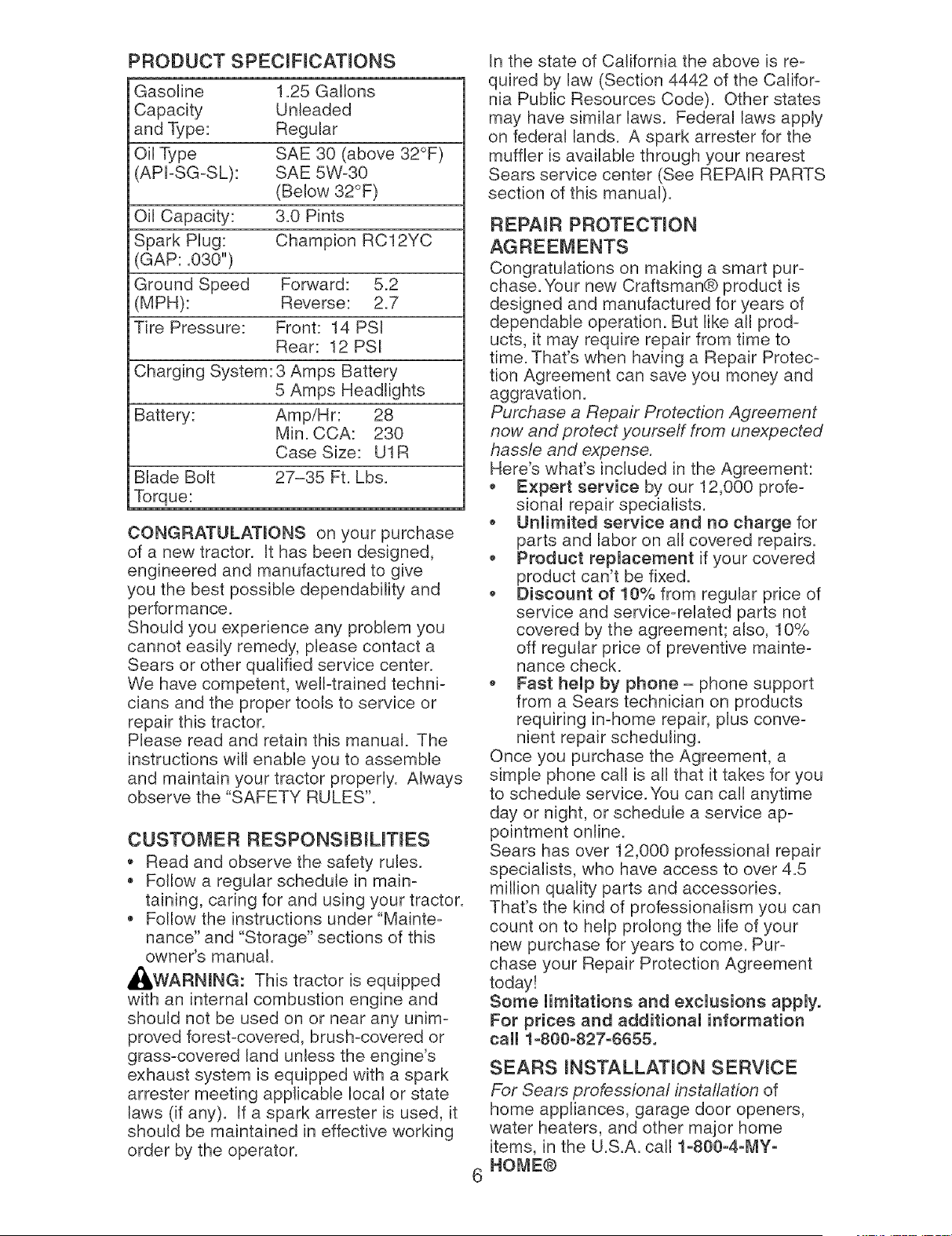
PRODUCT SPECIFmCATmONS
Gasoline 1.25 Gallons
Capacity Unleaded
and Type: Regular
Oil Type SAE 30 (above 32°F)
(API-SG-SL): SAE 5W-30
(Below 32°F)
Oil Capacity: 3.0 Pints
Spark Plug: Champion RC12YC
(GAP: .030")
Ground Speed Forward: 5.2
(MPH): Reverse: 2.7
Tire Pressure: Front: 14 PSI
Rear: 12 PSI
Charging System: 3 Amps Battery
5 Amps Headlights
Battery: Amp/Hr: 28
Min. CCA: 230
Case Size: U1R
Blade Bolt 27-35 Ft. Lbs.
Torque:
CONGRATULATmONS on your purchase
of a new tractor. It has been designed,
engineered and manufactured to give
you the best possible dependability and
performance.
Should you experience any problem you
cannot easily remedy, please contact a
Sears or other qualified service center.
We have competent, well-trained techni-
cians and the proper tools to service or
repair this tractor.
Please read and retain this manual. The
instructions will enable you to assemble
and maintain your tractor properly. Always
observe the "SAFETY RULES".
CUSTOMER RESPONSmBIUTIES
Read and observe the safety rules.
Follow a regular schedule in main-
taining, caring for and using your tractor.
Follow the instructions under "Mainte-
nance" and "Storage" sections of this
owner's manual.
_,WARNmNG: This tractor is equipped
with an internal combustion engine and
should not be used on or near any unim-
proved forest-covered, brush-covered or
grass-covered land unless the engine's
exhaust system is equipped with a spark
arrester meeting applicable local or state
laws (if any). If a spark arrester is used, it
should be maintained in effective working
order by the operator.
In the state of California the above is re-
quired by law (Section 4442 of the Califor-
nia Public Resources Code). Other states
may have similar laws. Federal laws apply
on federal lands. A spark arrester for the
muffler is available through your nearest
Sears service center (See REPAIR PARTS
section of this manual).
REPAmR PROTECTION
6
Congratulations on making a smart pur-
chase. Your new Craftsman® product is
designed and manufactured for years of
dependable operation. But like all prod-
ucts, it may require repair from time to
time. That's when having a Repair Protec-
tion Agreement can save you money and
aggravation.
Purchase a Repair Protection Agreement
now and protect yourseff from unexpected
hassle and expense.
Here's what's included in the Agreement:
Expert service by our 12,000 profe-
sional repair specialists.
, Unlimited service and no charge for
parts and labor on all covered repairs.
* Product replacement if your covered
product can't be fixed.
, Discount of 10% from regular price of
service and service-related parts not
covered by the agreement; also, 10%
off regular price of preventive mainte-
nance check.
* Fast help by phone- phone support
from a Sears technician on products
requiring in-home repair, plus conve-
nient repair scheduling.
Once you purchase the Agreement, a
simple phone call is all that it takes for you
to schedule service. You can call anytime
day or night, or schedule a service ap-
pointment online.
Sears has over 12,000 professional repair
specialists, who have access to over 4.5
million quality parts and accessories.
That's the kind of professionalism you can
count on to help prolong the life of your
new purchase for years to come. Pur-
chase your Repair Protection Agreement
today!
Some limitations and exclusions apply.
For prices and additional information
call 1o800o827=6655.
SEARS INSTALLATmON SERWCE
For Sears professional installation of
home appliances, garage door openers,
water heaters, and other major home
items, in the U.S.A. call 1o800o4o1_Yo
HOME®
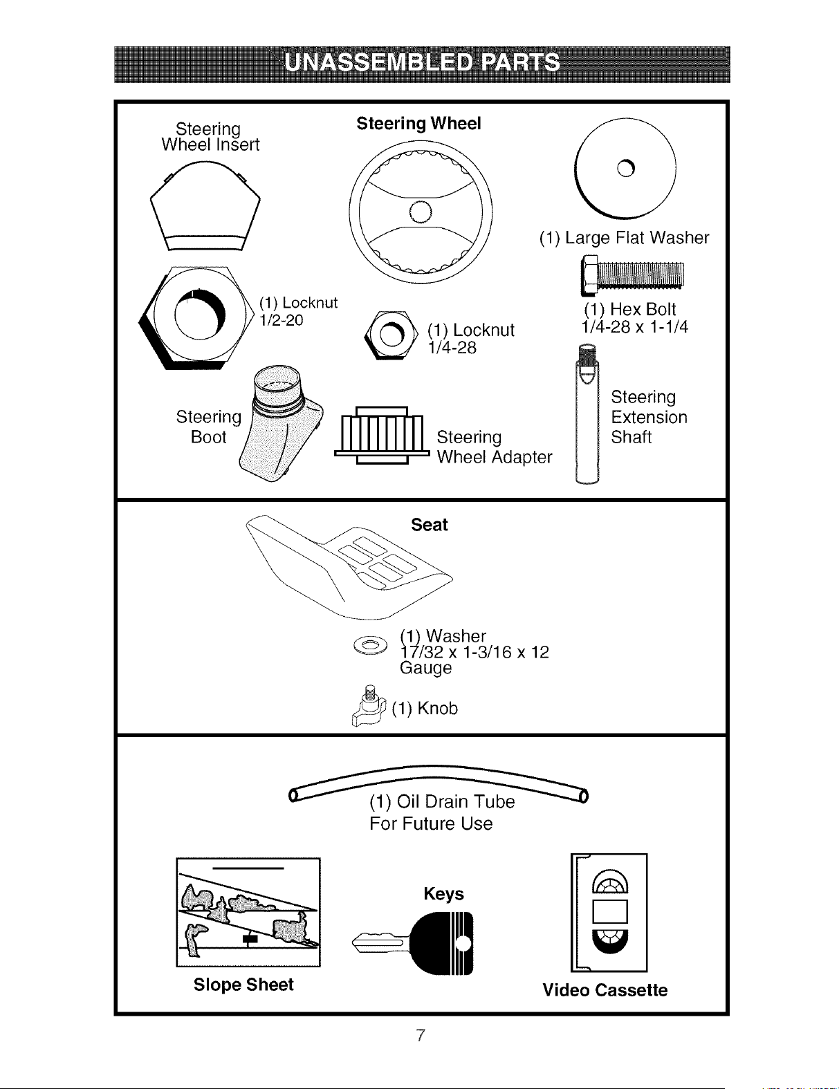
Steering
Wheel Insert
Steering j
Boot _
Steering Wheel
(1) Large Flat Washer
(1) Locknut
1/2-20 _ (1) Locknut
1/4-28
_ __] Steering
' ,, ' Wheel Adapter
(1) Hex Bolt
1/4-28 x 1-1/4
_ Steering
Extension
Shaft
Seat
(1) Washer
17/32 x 1-3/16 x 12
Gauge
_(1) Knob
For Future Use
Keys
Slope Sheet Video Cassette
Your new tractor has been assembled at the factory with the exception of those parts left
unassembled for shipping purposes. To ensure safe and proper operation of your tractor
all parts and hardware you assemble must be tightened securely. Use the correct tools
as necessary to insure proper tightness. Review the video cassette before you begin.
TOOLS REQUmRED FOR ASSEMBLY
A socket wrench set will make assembly
easier. Standard wrench sizes you need
are listed below.
(1) 3/4" wrench (1) Pliers
(2) 7/16" wrench (1) Utility knife
(1) Tire pressure gauge
When right or left hand is mentioned in
this manual, it means, from your point of
view, when you are in the operating posi-
tion (seated behind the steering wheel).
TO REMOVE TRACTOR FROM
CARTON
UNPACK CARTON
1. Remove all accessible loose parts and
parts boxes from carton.
2. Cut along dotted lines on all four pan-
els of carton. Remove end panels and
lay side panels flat.
3. Check for any additional loose parts or
cartons and remove.
BEFORE REMOVmNG TRACTOR
FROM SKID
ATTACH STEERmNG WHEEL
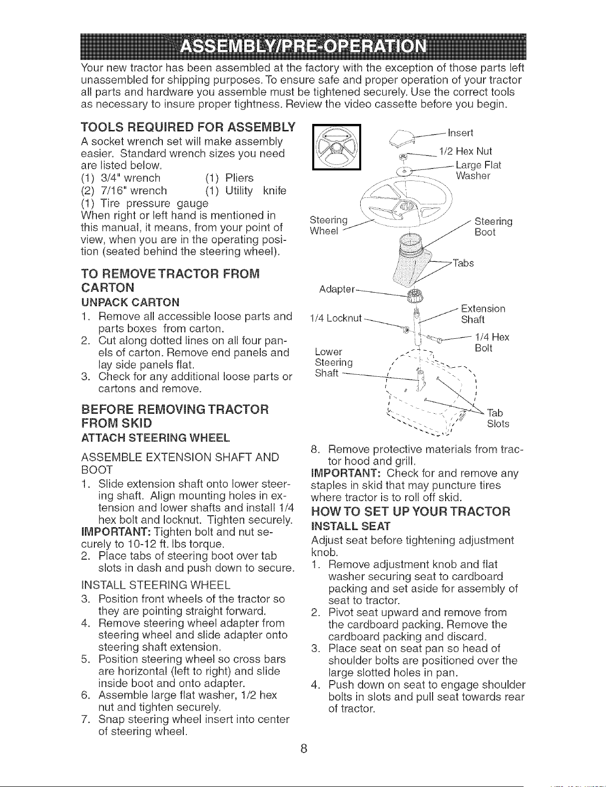
ASSEMBLE EXTENSION SHAFT AND
BOOT
1. Slide extension shaft onto lower steer-
ing shaft. Align mounting holes in ex-
tension and lower shafts and install 1/4
hex bolt and Iocknut. Tighten securely.
mMPORTANT: Tighten bolt and nut se-
curely to 10-12 ft. Ibs torque.
2. Place tabs of steering boot over tab
slots in dash and push down to secure.
INSTALL STEERING WHEEL
3. Position front wheels of the tractor so
they are pointing straight forward.
4. Remove steering wheel adapter from
steering wheel and slide adapter onto
steering shaft extension.
5. Position steering wheel so cross bars
are horizontal (left to right) and slide
inside boot and onto adapter.
6. Assemble large fiat washer, 1/2 hex
nut and tighten securely.
7. Snap steering wheel insert into center
of steering wheel.
Steering
Wheel
1/4 Locknut
Slots
8. Remove protective materials from trac-
tor hood and grill.
IMPORTANT: Check for and remove any
staples in skid that may puncture tires
where tractor is to roll off skid.
HOW TO SET UP YOUR TRACTOR
mNSTALL SEAT
Adjust seat before tightening adjustment
knob.
1. Remove adjustment knob and flat
washer securing seat to cardboard
packing and set aside for assembly of
seat to tractor.
2. Pivot seat upward and remove from
the cardboard packing. Remove the
cardboard packing and discard.
3. Place seat on seat pan so head of
shoulder bolts are positioned over the
large slotted holes in pan.
4. Push down on seat to engage shoulder
bolts in slots and pull seat towards rear
of tractor.
8
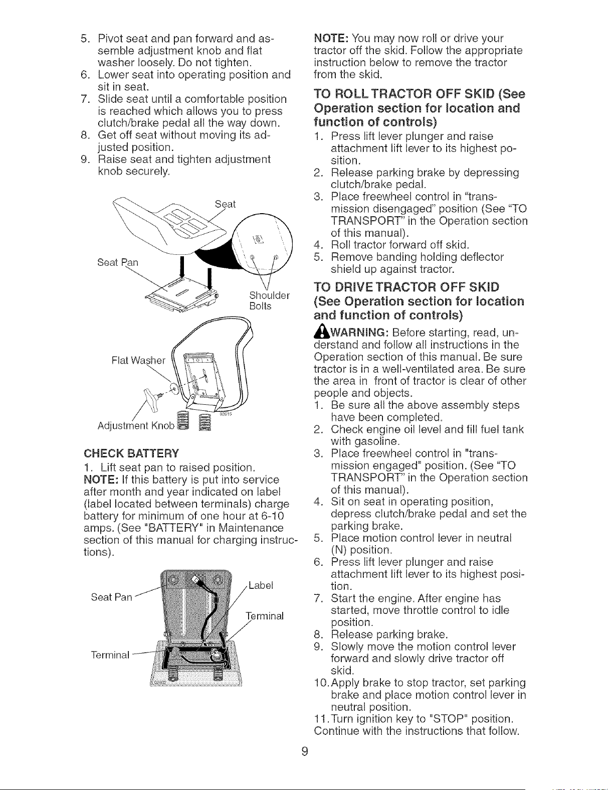
5. Pivot seat and pan forward and as-
semble adjustment knob and fiat
washer loosely. Do not tighten.
6. Lower seat into operating position and
sit in seat.
7. Slide seat until a comfortable position
is reached which atlows you to press
clutch/brake pedal atl the way down.
8. Get off seat without moving its ad-
justed position.
9. Raise seat and tighten adjustment
knob securely.
Seat
Seat
ShouUder
BoUts
Fiat Washer
Adjustment Knob l
CHECK BATTERY
1. Lift seat pan to raised position.
NOTE: If this battery is put into service
after month and year indicated on label
(label located between terminals) charge
battery for minimum of one hour at 6-10
amps. (See "BATTERY" in Maintenance
section of this manual for charging instruc-
tions).
Seat Pan
Terminal
Terminal
NOTE: You may now roll or drive your
tractor off the skid. Follow the appropriate
instruction below to remove the tractor
from the skid.
TO ROLL TRACTOR OFF SKID (See
Operation section for mocation and
function of controms)
1. Press lift lever plunger and raise
attachment lift lever to its highest po-
sition.
2. Release parking brake by depressing
clutch/brake pedal.
3. Place freewheel control in "trans-
mission disengaged" position (See "TO
TRANSPORT" in the Operation section
of this manual).
4. Roll tractor forward off skid.
5. Remove banding holding deflector
shbid up against tractor.
TO DRmVE TRACTOR OFF SKID
(See Operation section for mocation
and function of controms)
_,WARNmNG: Before starting, read, un-
derstand and follow all instructions in the
Operation section of this manual. Be sure
tractor is in a welPventilated area. Be sure
the area in front of tractor is clear of other
people and objects.
1. Be sure all the above assembly steps
have been completed.
2. Check engine oil level and fill fuel tank
with gasoline.
3. Place freewheel control in "trans-
mission engaged" position. (See "TO
TRANSPORT" in the Operation section
of this manual).
4. Sit on seat in operating position,
depress clutch/brake pedal and set the
parking brake.
5. Place motion control lever in neutral
(N) position.
6. Press lift lever plunger and raise
attachment lift lever to its highest posi-
tion.
7. Start the engine. After engine has
started, move throttle control to idle
position.
8. Release parking brake.
9. Slowly move the motion control lever
forward and slowly drive tractor off
skid.
10.Apply brake to stop tractor, set parking
brake and place motion control lever in
neutral position.
11 .Turn ignition key to "STOP" position.
Continue with the instructions that follow.
9
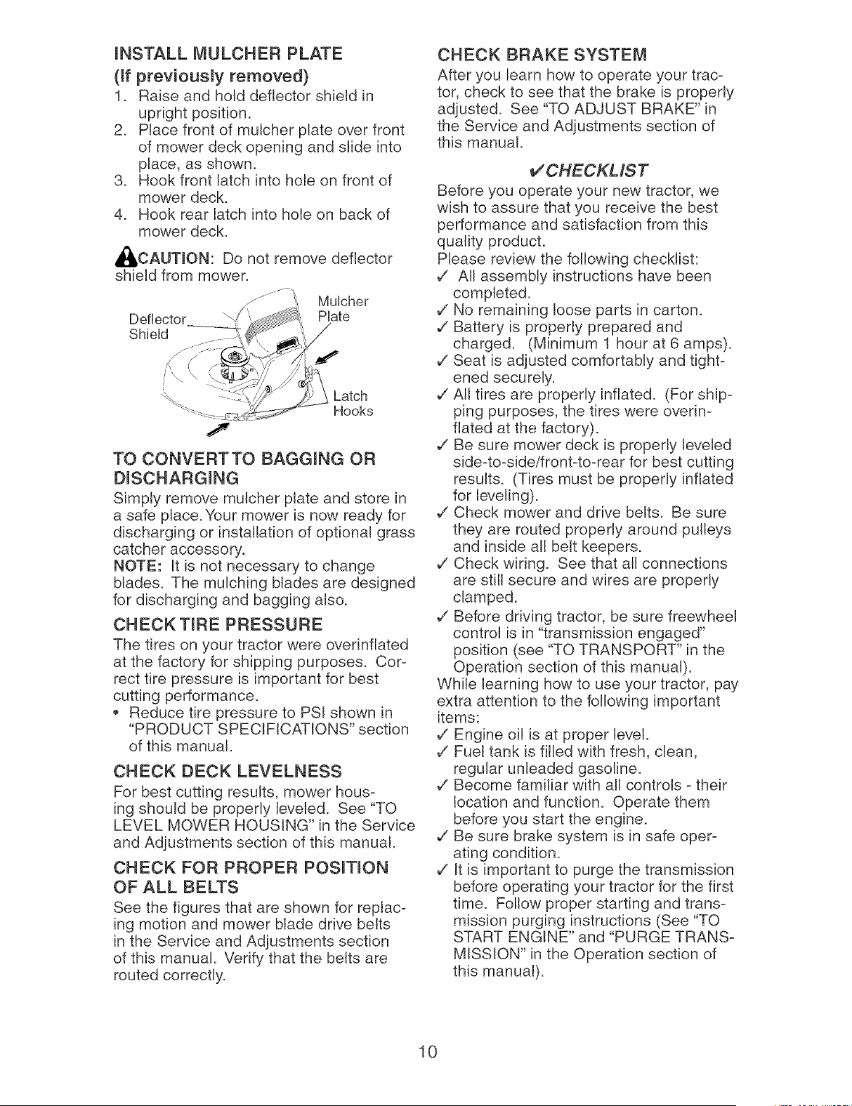
mNSTALL MULCHER PLATE
(if previousmy removed)
1. Raise and hold deflector shield in
upright position.
2. Place front of mutcher plate over front
of mower deck opening and slide into
place, as shown.
3. Hook front latch into hole on front of
mower deck.
4. Hook rear latch into hole on back of
mower deck.
_I, CAUTmON: Do not remove deflector
shield from mower.
Deflector
ShieUd
MuUcher
Plate
Latch
Hooks
TO CONVERTTO BAGGmNG OR
DISCHARGmNG
Simply remove mulcher plate and store in
a safe place. Your mower is now ready for
discharging or installation of optional grass
catcher accessory.
NOTE: It is not necessary to change
blades. The mulching blades are designed
for discharging and bagging also.
CHECK TIRE PRESSURE
The tires on your tractor were overinfiated
at the factory for shipping purposes. Cor-
rect tire pressure is important for best
cutting performance.
Reduce tire pressure to PSI shown in
"PRODUCT SPECIFICATIONS" section
of this manual.
CHECK DECK LEVELNESS
For best cutting results, mower hous-
ing should be properly leveled. See "TO
LEVEL MOWER HOUSING" in the Service
and Adjustments section of this manual.
CHECK FOR PROPER POSmTmON
OF ALL BELTS
See the figures that are shown for replac-
ing motion and mower blade drive belts
in the Service and Adjustments section
of this manual. Verify that the belts are
routed correctly.
CHECK BRAKE SYSTEM
After you learn how to operate your trac-
tor, check to see that the brake is properly
adjusted. See "TO ADJUST BRAKE" in
the Service and Adjustments section of
this manual.
VCHECKMST
Before you operate your new tractor, we
wish to assure that you receive the best
performance and satisfaction from this
quality product.
Please review the following checklist:
,/ All assembly instructions have been
completed.
,/No remaining loose parts in carton.
,/Battery is properly prepared and
charged. (Minimum 1 hour at 6 amps).
,/Seat is adjusted comfortably and tight-
ened securely.
,/All tires are properly inflated. (For ship-
ping purposes, the tires were overin-
fiated at the factory).
,/Be sure mower deck is properly leveled
side-to-side/front-to-rear for best cutting
results. (Tires must be properly inflated
for leveling).
,/Check mower and drive belts. Be sure
they are routed properly around pulleys
and inside all belt keepers.
,/Check wiring. See that all connections
are still secure and wires are properly
clamped.
,/Before driving tractor, be sure freewheel
control is in "transmission engaged"
position (see "TO TRANSPORT" in the
Operation section of this manual).
While learning how to use your tractor, pay
extra attention to the following important
items:
,/Engine oil is at proper level.
,/Fuel tank is filled with fresh, clean,
regular unleaded gasoline.
,/Become familiar with all controls - their
location and function. Operate them
before you start the engine.
,/Be sure brake system is in safe oper-
ating condition.
,/It is important to purge the transmission
before operating your tractor for the first
time. Follow proper starting and trans-
mission purging instructions (See "TO
START ENGINE" and "PURGE TRANS-
MISSION" in the Operation section of
this manual).
10
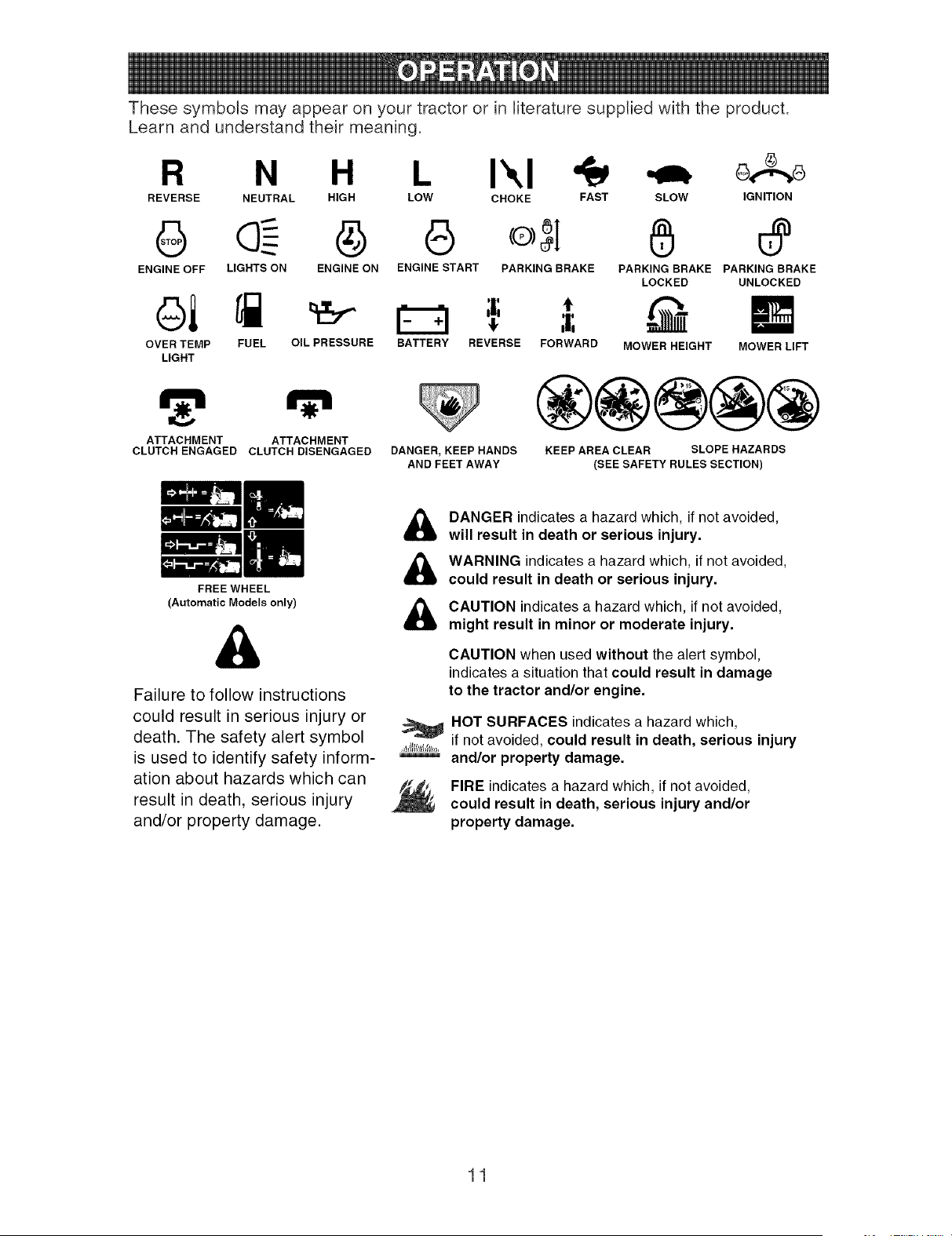
These symbols may appear on your tractor or in literature supplied with the product.
Learn and understand their meaning.
R N H I\1 o,. o
REVERSE NEUTRAL HIGH LOW CHOKE FAST SLOW IGNITION
G @ G o;I
ENGINE OFF LIGHTS ON ENGINE ON ENGINE START PARKING BRAKE
OVER TEMP FUEL OIL PRESSURE
LIGHT
ATTACHMENT ATTACHMENT
CLUTCH ENGAGED CLUTCH DISENGAGED
FREE WHEEL
(Automatic Models only)
,T,
BATTERY REVERSE FORWARD
6
PARKING BRAKE PARKING BRAKE
LOCKED UNLOCKED
MOWER HEIGHT MOWER LIFT
DANGER, KEEP HANDS
AND FEET AWAY
®@@@@
KEEP AREA CLEAR SLOPE HAZARDS
(SEE SAFETY RULES SECTION)
Failure to follow instructions
could result in serious injury or
death. The safety alert symbol
is used to identify safety inform-
ation about hazards which can
result in death, serious injury
and/or property damage.
DANGER indicates a hazard which, if not avoided,
will result in death or serious injury.
WARNING indicates a hazard which, if not avoided,
could result in death or serious injury.
CAUTION indicates a hazard which, if not avoided,
might result in minor or moderate injury.
CAUTION when used without the alert symbol,
indicates a situation that could result in damage
to the tractor and/or engine.
HOT SURFACES indicatesa hazard which,
if not avoided, could result in death, serious injury
and/or property damage.
FIRE indicatesa hazard which, if not avoided,
could result in death, serious injury and/or
property damage.
11
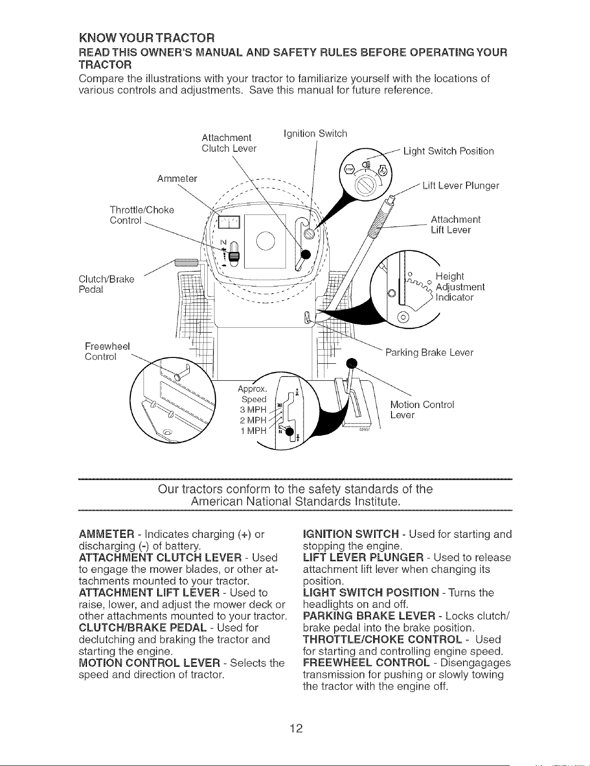
KNOW YOUR TRACTOR
READTHINSOWNER'SMANUAL AND SAFETY RULESBEFORE OPERATmNGYOUR
TRACTOR
Comparethe illustrations'withyour tractorto familiarizeyourselfwith the locationsof
variouscontrolsand adjustments. Savethis manualfor future reference.
Attachment
CDtch Lever
ignition Switch
Light Switch Position
Ammeter
.::. --::--.. ger
Throttb/Choke
Control Attachment
Lift Lever
Clutch/Brake
Pedal
Freewheel
Control
Parking Brake Lever
Approx.
Speed Motion Control
3 MPH
Lever
2
1
Our tractors conform to the safety standards of the
American National Standards anstitute.
AMMETER - Indicates charging (+) or
discharging (-) of battery.
ATTACHMENT CLUTCH LEVER - Used
to engage the mower blades, or other at-
tachments mounted to your tractor.
ATTACHMENT UFT LEVER - Used to
raise, lower, and adjust the mower deck or
other attachments mounted to your tractor.
CLUTCH/BRAKE PEDAL - Used for
declutching and braking the tractor and
starting the engine.
MOTmON CONTROL LEVER - Selects the
speed and direction of tractor.
mGNmON SWmTCH - Used for starting and
stopping the engine.
LIFT LEVER PLUNGER - Used to release
attachment lift lever when changing its
position.
UGHT SWmTCH POSITION - Turns the
headlights on and off.
PARKING BRAKE LEVER - Locks clutch/
brake pedal into the brake position.
THROTTLE/CHOKE CONTROL - Used
for starting and controlling engine speed.
FREEWHEEL CONTROL = Disengagages
transmission for pushing or slowly towing
the tractor with the engine off.
12
The operation of any tractor can result in foreign objects thrown into the
eyes, which can result in severe eye damage. Always wear safety glasses
or eye shields while operating your tractor or performing any adjustments
or repairs. We recommend standard safety glasses or a wide vision safety
mask worn over spectacles.
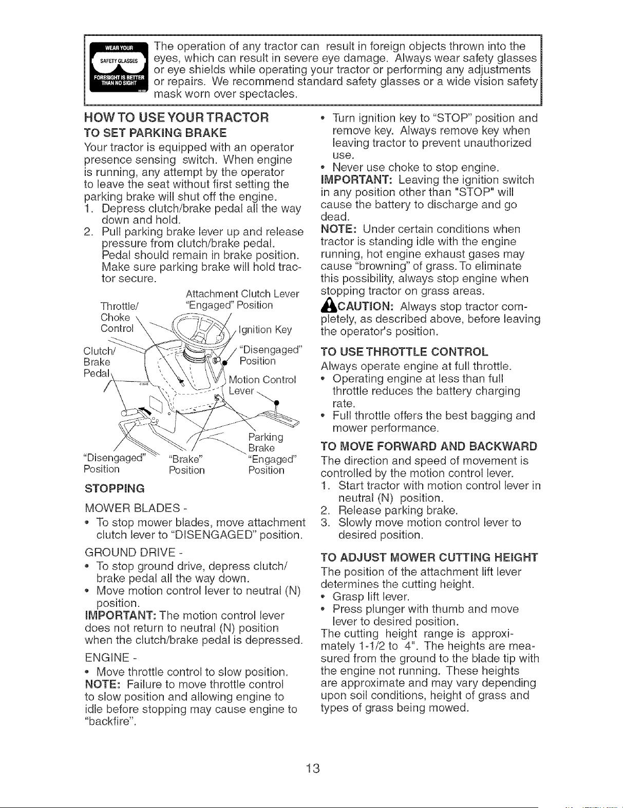
HOW TO USE YOUR TRACTOR
TO SET PARKmNG BRAKE
Your tractor is equipped with an operator
presence sensing switch. When engine
is running, any attempt by the operator
to leave the seat without first setting the
parking brake will shut off the engine.
1. Depress clutch/brake pedal all the way
down and hold.
2. Pull parking brake lever up and release
pressure from clutch/brake pedal.
Pedal should remain in brake position.
Make sure parking brake will hold trac-
tor secure.
Throttle/
Choke \
ControU\
Attachment CUutchLever
"Engaged" Position
Ugnition Key
Clutch/ "Disengaged"
Brake Position
Motion Control
Lever
_-_ Parking
Brake
"Disengaged" "Brake .... Engaged"
Position Position Position
STOPPmNG
MOWER BLADES -
To stop mower blades, move attachment
clutch lever to "DISENGAGED" position.
GROUND DRIVE -
To stop ground drive, depress clutch/
brake pedal all the way down.
Move motion control lever to neutral (N)
position.
mMPORTANT: The motion control lever
does not return to neutral (N) position
when the clutch/brake pedal is depressed.
ENGINE -
Move throttle control to slow position.
NOTE: Failure to move throttle control
to slow position and allowing engine to
idle before stopping may cause engine to
"backfire".
Turn ignition key to "STOP" position and
remove key. Always remove key when
leaving tractor to prevent unauthorized
use.
Never use choke to stop engine.
mMPORTANT: Leaving the ignition switch
in any position other than "STOP" will
cause the battery to discharge and go
dead.
NOTE: Under certain conditions when
tractor is standing idle with the engine
running, hot engine exhaust gases may
cause "browning" of grass. To eliminate
this possibility, always stop engine when
stopping tractor on grass areas.
_,CAUTmON: Always stop tractor com-
pletely, as described above, before leaving
the operator's position.
TO USE THROTTLE CONTROL
Always operate engine at full throttle.
Operating engine at less than full
throttle reduces the battery charging
rate.
Full throttle offers the best bagging and
mower performance.
TO MOVE FORWARD AND BACKWARD
The direction and speed of movement is
controlled by the motion control lever.
1. Start tractor with motion control lever in
neutral (N) position.
2. Release parking brake.
3. Slowly move motion control lever to
desired position.
TO ADJUST MOWER CUTTmNG HEmGHT
The position of the attachment lift lever
determines the cutting height.
Grasp lift lever.
Press plunger with thumb and move
lever to desired position.
The cutting height range is approxi-
mately 1-1/2 to 4". The heights are mea-
sured from the ground to the blade tip with
the engine not running. These heights
are approximate and may vary depending
upon soil conditions, height of grass and
types of grass being mowed.
13
,, The average lawn should be cut to ap-
proximately 2-1/2 inches during the cool
season and to over 3 inches during hot
months. For healthier and better looking
lawns, mow often and after moderate
growth.
,, For best cutting performance, grass over
6 inches in height should be mowed
twice. Make the first cut relatively high;
the second to desired height.
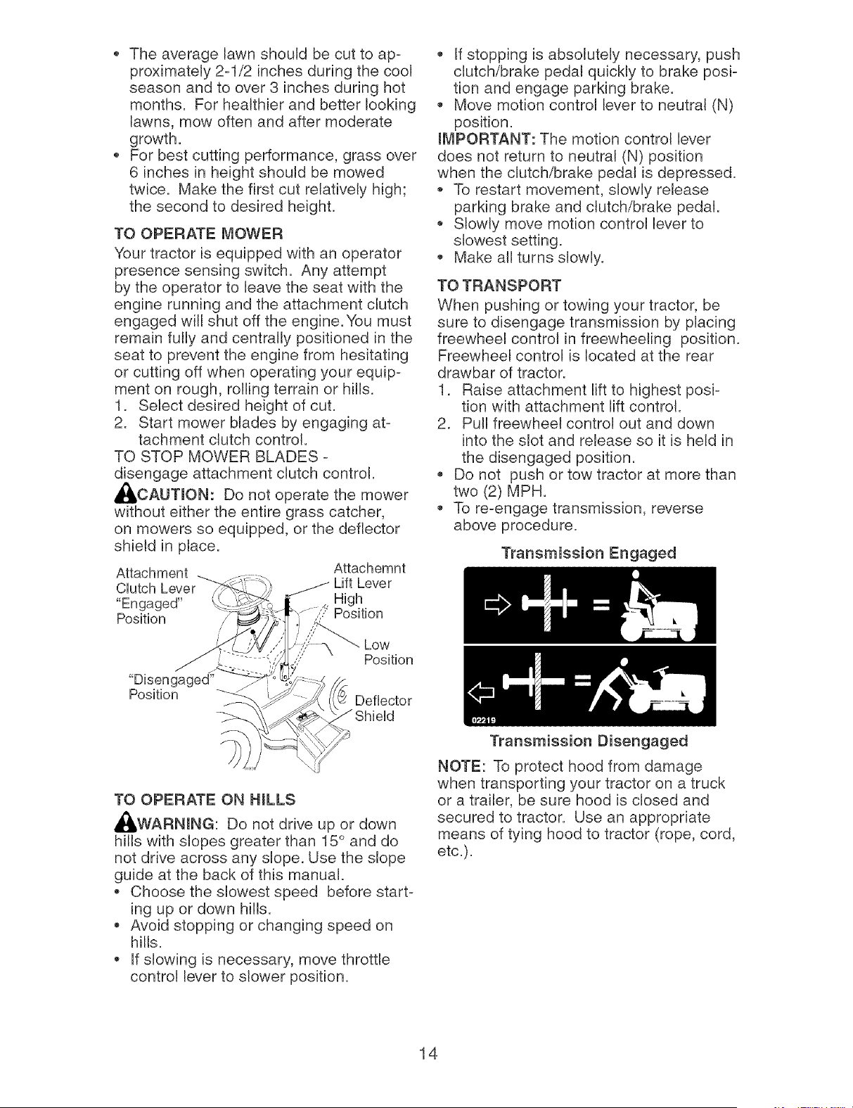
TO OPERATE MOWER
Your tractor is equipped with an operator
presence sensing switch. Any attempt
by the operator to leave the seat with the
engine running and the attachment clutch
engaged will shut off the engine. You must
remain fully and centrally positioned in the
seat to prevent the engine from hesitating
or cutting off when operating your equip-
ment on rough, rolling terrain or hills.
1. Select desired height of cut.
2. Start mower blades by engaging at-
tachment clutch control.
TO STOP MOWER BLADES -
disengage attachment clutch control.
_I, CAUTION: Do not operate the mower
without either the entire grass catcher,
on mowers so equipped, or the deflector
shield in place.
Attachemnt
', If stopping is absolutely necessary, push
clutch/brake pedal quickly to brake posi-
tion and engage parking brake.
,, Move motion control lever to neutral (N)
position.
IMPORTANT: The motion control lever
does not return to neutral (N) position
when the clutch/brake pedal is depressed.
,_ To restart movement, slowly release
parking brake and clutch/brake pedal.
,_ Slowly move motion control lever to
slowest setting.
,, Make all turns slowly.
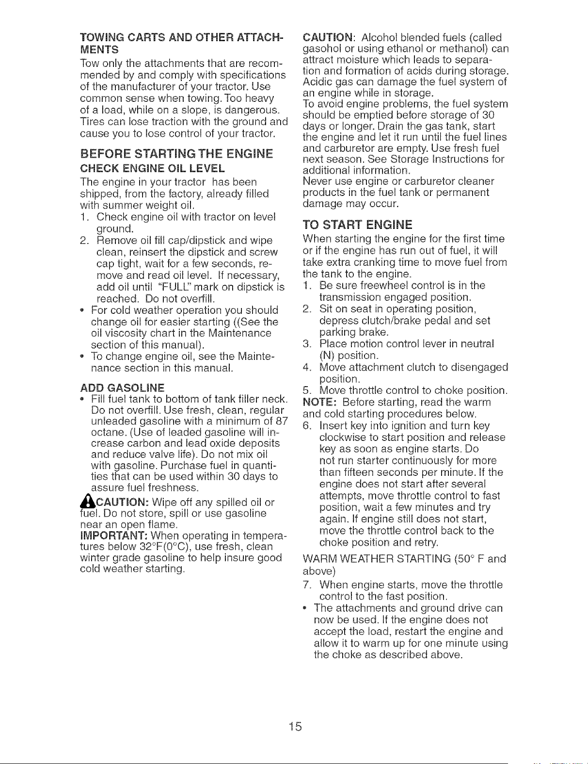
TO TRANSPORT
When pushing or towing your tractor, be
sure to disengage transmission by placing
freewheel control in freewheeling position.
Freewheel control is located at the rear
drawbar of tractor.
1. Raise attachment lift to highest posi-
tion with attachment lift control.
2. Pull freewheel control out and down
into the slot and release so it is held in
the disengaged position.
,, Do not push or tow tractor at more than
two (2) MPH.
,, To re-engage transmission, reverse
above procedure.
Transmission Engaged
Position
TO OPERATE ON HILLS
,_,WARNING: Do not drive up or down
hills with slopes greater than 15 ° and do
not drive across any slope. Use the slope
guide at the back of this manual.
,, Choose the slowest speed before start-
ing up or down hills.
,, Avoid stopping or changing speed on
hills.
,, If slowing is necessary, move throttle
control lever to slower position.
Transmission Disengaged
NOTE: To protect hood from damage
when transporting your tractor on a truck
or a trailer, be sure hood is closed and
secured to tractor. Use an appropriate
means of tying hood to tractor (rope, cord,
etc.).
14
TOWING CARTS AND OTHER ATTACH-
rvIENTS
Tow only the attachments that are recom-
mended by and comply with specifications
of the manufacturer of your tractor. Use
common sense when towing. Too heavy
of a load, while on a slope, is dangerous.
Tires can lose traction with the ground and
cause you to lose control of your tractor.
BEFORE STARTmNG THE ENGmNE
CHECK ENGmNE OraL LEVEL
The engine in your tractor has been
shipped, from the factory, already filled
with summer weight oil.
1. Check engine oil with tractor on level
ground.
2. Remove oil fill cap/dipstick and wipe
clean, reinsert the dipstick and screw
cap tight, wait for a few seconds, re-
move and read oil level. If necessary,
add oil until "FULF' mark on dipstick is
reached. Do not overfill.
For cold weather operation you should
change oil for easier starting ((See the
oil viscosity chart in the Maintenance
section of this manual).
To change engine oil, see the Mainte-
nance section in this manual.
ADD GASOUNE
Fill fuel tank to bottom of tank filler neck.
Do not overfill. Use fresh, clean, regular
unleaded gasoline with a minimum of 87
octane. (Use of leaded gasoline will in-
crease carbon and lead oxide deposits
and reduce valve life). Do not mix oil
with gasoline. Purchase fuel in quanti-
ties that can be used within 30 days to
assure fuel freshness.
,_I, CAUTmON: Wipe off any spilled oil or
fuel. Do not store, spill or use gasoline
near an open flame.
mMPORTANT: When operating in tempera-
tures below 32°F(0°C), use fresh, clean
winter grade gasoline to help insure good
cold weather starting.
CAUTION: Alcohol blended fuels (called
gasohol or using ethanol or methanol) can
attract moisture which leads to separa-
tion and formation of acids during storage.
Acidic gas can damage the fuel system of
an engine while in storage.
To avoid engine problems, the fuel system
should be emptied before storage of 30
days or longer. Drain the gas tank, start
the engine and let it run until the fuel lines
and carburetor are empty. Use fresh fuel
next season. See Storage Instructions for
additional information.
Never use engine or carburetor cleaner
products in the fuel tank or permanent
damage may occur.
TO START ENGmNE
When starting the engine for the first time
or if the engine has run out of fuel, it will
take extra cranking time to move fuel from
the tank to the engine.
1. Be sure freewheel control is in the
transmission engaged position.
2. Sit on seat in operating position,
depress clutch/brake pedal and set
parking brake.
3. Place motion control lever in neutral
(N) position.
4. Move attachment clutch to disengaged
position.
5. Move throttle control to choke position.
NOTE: Before starting, read the warm
and cold starting procedures below.
6. Insert key into ignition and turn key
clockwise to start position and release
key as soon as engine starts. Do
not run starter continuously for more
than fifteen seconds per minute. If the
engine does not start after several
attempts, move throttle control to fast
position, wait a few minutes and try
again. If engine still does not start,
move the throttle control back to the
choke position and retry.
WARM WEATHER STARTING (50 ° F and
above)
7. When engine starts, move the throttle
control to the fast position.
The attachments and ground drive can
now be used. If the engine does not
accept the load, restart the engine and
allow it to warm up for one minute using
the choke as described above.
15
COLD WEATHER STARTING ( 50 ° F and
below)
7. When engine starts, allow engine
to run with the throttle control in the
choke position until the engine runs
roughly, then move throttle control
to fast position. This may require an
engine warm-up period from several
seconds to several minutes, depending
on the temperature.
AUTOMATIC TRANSMISSION WARM UP
Before driving the unit in cold weather,
the transmission should be warmed up as
follows:
1. Be sure the tractor is on level ground.
2. Place the motion control lever in
neutral. Release the parking brake
and let the clutch/brake slowly return
to operating position.
3. Allow one minute for transmission to
warm up. This can be done during
the engine warm up period.
• The attachments can also be used dur-
ing the engine warm-up period after the
transmission has been warmed up.
NOTE: If at a high altitude (above 3000
feet) or in cold temperatures (below 32 F)
the carburetor fuel mixture may need to
be adjusted for best engine performance.
(See "TO ADJUST CARBURETOR" in the
Service and Adjustments section of this
manual.)
PURGE TRANSMISSmON
To ensure proper operation and per-
formance, it is recommended that the
transmission be purged before operating
tractor for the first time. This procedure will
remove any trapped air inside the trans-
mission which may have developed during
shipping of your tractor.
mMPORTANT: Should your transmission
require removal for service or replace-
ment, it should be purged after reinstall-
ation before operating the tractor.
1. Place tractor safely in an area that is
flat for approximately 80 feet in front of
the tractor and set the parking brake.
2. Sitting in the tractor seat, start engine.
After the engine is running, move
throttle control to slow position. With
motion control lever in neutral (N)
position, slowly disengage clutch/brake
pedal.
3. Slowly move motion control lever to
full forward position and hold for five
(5) seconds, or approximately 40 feet.
Slowly move lever to full reverse posi-
tion and hold for five (5) seconds, or
approximately 20 feet. After the tractor
moves approximately 20 feet in reverse
return the motion control lever to the
neutral (N) position. Repeat this proce-
dure three (3) times.
Your transmission is now purged and now
ready for normal operation.
16

MOWmNG TraPS
Mower should be properly leveled for
best mowing performance. See "TO
LEVEL MOWER HOUSING" in the
Service and Adjustments section of this
manual.
The left hand side of mower should be
used for trimming.
Drive so that clippings are discharged
onto the area that has already been
cut. Have the cut area to the right of
the tractor. This will result in a more
even distribution of clippings and more
uniform cutting.
When mowing large areas, start by
turning to the right so that clippings will
discharge away from shrubs, fences,
driveways, etc. After one or two rounds,
mow in the opposite direction making
left hand turns until finished.
f
1
J
00272
If grass is extremely tall, it should be
mowed twice to reduce load and pos-
sible fire hazard from dried clippings.
Make first cut relatively high; the second
to the desired height.
Do not mow grass when it is wet.
Wet grass will plug mower and leave
undesirable clumps. Allow grass to dry
before mowing.
Always operate engine at full throttle
when mowing to assure better mow-
ing performance and proper discharge
of material. Regulate ground speed by
selecting a low enough gear to give the
mower cutting performance as well as
the quality of cut desired.
• When operating attachments, select a
ground speed that will suit the terrain
and give best performance of the at-
tachment being used.
MULCHmNG MOWING TIPS
mMPORTANT: For best performance, keep
mower housing free of built-up grass and
trash. Clean after each use.
The special mulching blade will recut
the grass clippings many times and
reduce them in size so that as they fall
onto the lawn they will disperse into
the grass and not be noticed. Also, the
mulched grass will biodegrade quickly
to provide nutrients for the lawn. Always
mulch with your highest engine (blade)
speed as this will provide the best recut-
ting action of the blades.
Avoid cutting your lawn when it is wet.
Wet grass tends to form clumps and
interferes with the mulching action. The
best time to mow your lawn is the early
afternoon. At this time the grass has
dried, the newly cut area will not be
exposed to direct sunlight.
For best results, adjust the mower
cutting height so that the mower cuts
off only the top one=third of the grass
blades. For extremely heavy grass, re-
duce your width of cut on each pass and
mow slowly.
MAX 1/3
Certain types of grass and grass
conditions may require that an area be
mulched a second time to completely
hide the clippings. When doing a sec-
ond cut, mow across (perpendicular) to
the first cut path.
Change your cutting pattern from week
to week. Mow north to south one week
then change to east to west the next
week. This will help prevent matting and
graining of the lawn.
17
MA,.TE.A.CESC.EOU'E
FILL IN DATES /_/_X'x_'_/_ _ "
AS YOU COMPLETE /__/_ _4 _/_/O.Oq.7"
REGULAR SERVICE /_r/_'Ac_I_SERVICE DATES
: hh:; kkBira:p r:::_;i° n _
Check Operator Presence and
i Interlock Systems I_
R Check for Loose Fasteners If I_s If
A Sharpen/Replace Mower Blades 1_3
C Lubrication Chart I_ If
O Check Battery Level 1_4
R Clean Battery and Terminals I_ If
Check Transaxle Cooling
Check V-Belts If
Check Engine Oil Level If I_
Change Engine Oil (with oil filter) I_1,_ If
E Change Engine Oil (without oil filter) 11_1,2 I_
N Clean Air Filter 1_2
G Clean Air Screen 1_2
Inspect Muffler/Spark
Arrester
v'
i= Replace Oil Filter (If equipped) _1,2
Clean Engine Cooling Fins If
Replace Spark Plug If If
Replace Air Filter Paper Cartridge 1_2
Replace Fuel Filter
1 - Change more often when operating under a heavy load or
in high ambient temperatures.
2 - Service more often when operating in dirty or dusty conditions,
GENERAL RECOMMENDATIONS
The warranty on this tractor does not
cover items that have been subjected to
operator abuse or negligence. To receive
full value from the warranty, operator
must maintain tractor as instructed in this
manual.
Some adjustments will need to be made
periodically to properly maintain your
tractor.
At least once a season, check to see if
you should make any of the adjustments
described in the Service and Adjustments
section of this manual.
• At least once a year you should replace
the spark plug, clean or replace air filter,
and check blades and belts for wear.
A new spark plug and clean air filter
assure proper air-fuel mixture and help
your engine run better and last longer.
BEFORE EACH USE
1. Check engine oil level.
2. Check brake operation.
3. Check tire pressure.
4. Check operator presence and
interlock systems for proper operation.
5. Check for loose fasteners.
3 - Replace blades more often when mowing in sandy soil.
4 - Not required if equipped with maintenance-free battery.
5 - Tighten front axle pivot bolt to 35 ft.-Ibs, maximum.
Do not overtighten,
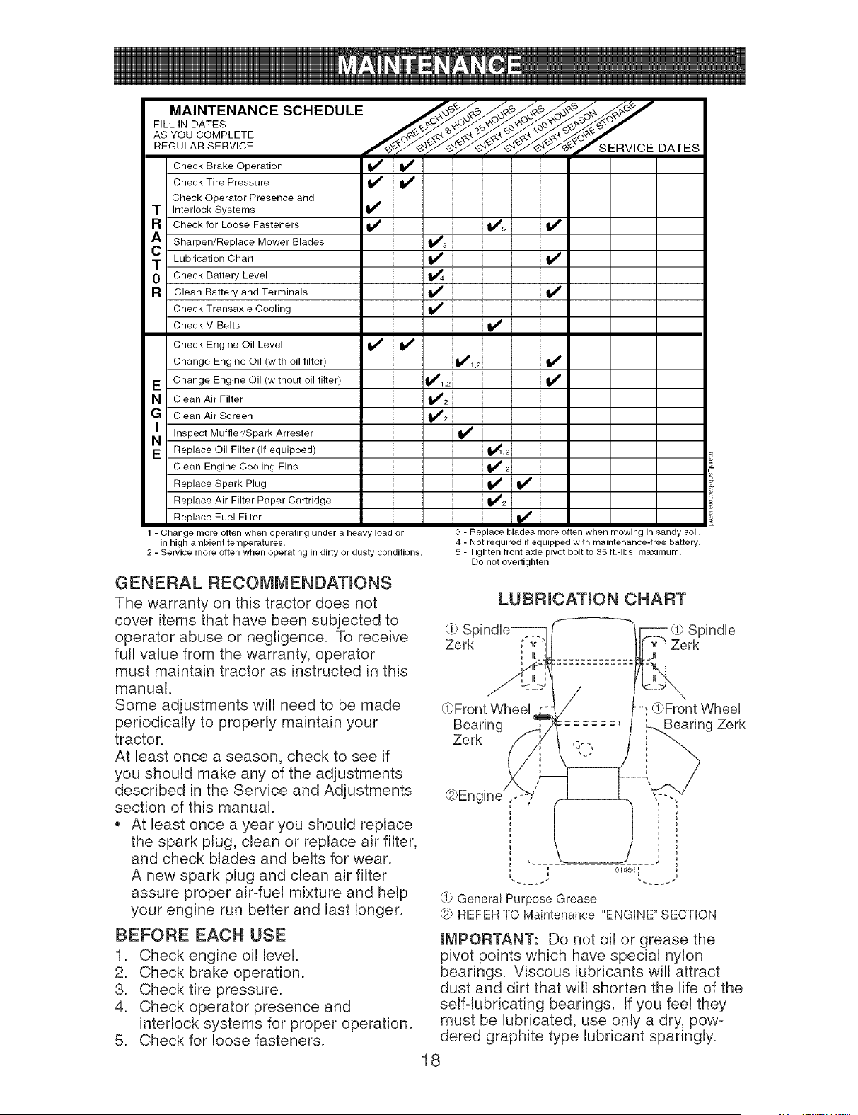
LUBRICATION CHART
_0 SF Spindle
Zerk __r Zerk
n
(J}Front Wheel ;(OFront Wheel
Bearing ........ ,L_Beanng Zerk
Zerk
@Engine ,, ,, "--,,
i i
,,! !
, ', 01964;
_f_General Purpose Grease
_2PREFER TO Maintenance "ENGINE" SECTION
IMPORTANT: Do not oil or grease the
pivot points which have special nylon
bearings. Viscous lubricants will attract
dust and dirt that will shorten the life of the
self-lubricating bearings. If you feel they
must be lubricated, use only a dry, pow-
dered graphite type lubricant sparingly.
18

TRACTOR
Alwaysobserve safety ruleswhen per-
forming any maintenance.
BRAKE OPERATmON
If tractor requiresmore than six (6) feet
stopping distanceat highspeed in highest
gear, then brakemust be adjusted.(See
"TOADJUSTBRAKE"in the Service and
Adjustmentssection of this manual).
TmRES
* Maintainproperair pressure in all tires
(See "PRODUCTSPECIFICATIONS"
section of this manual).
, Keeptires free of gasoline,oil, or insect
control chemicalswhichcan harm rub-
ber.
* Avoidstumps,stones,deep ruts, sharp
objectsand other hazardsthat may
cause tire damage.
NOTE:Toseat tire puncturesand prevent
flat tiresdue to slow leaks, tire sealant
maybe purchasedfromyour local parts
dealer.Tire sealant also preventstire dry
rot and corrosion.
OPERATORPRESENCESYSTEM
Besure operatorpresenceand interlock
systemsare working properly. Ifyour trac-
tor does not functionas described,repair
the problemimmediately.
The engine should notstart unless
the brakepedal is fully depressedand
attachementclutch control is in the
disengagedposition.
When the engine is running,any at-
tempt bythe operator to leavethe seat
without first setting the parkingbrake
should shut off the engine.
When the engine is runningand the
attachmentclutch isengaged,any at-
tempt bythe operator to leavethe seat
should shut off the engine.
The attachmentclutch should neverop-
erate unlessthe operator is in the seat.
BLADE CARE
For bestresults mowerblades mustbe
keptsharp. Replacebent or damaged
blades.
BLADE REMOVAL
1. Raisemowerto highestpositionto al-
low accessto blades.
2. Removeblade bolt, lockwasherand
flat washer securing blade.
3. Install new or resharpenedblade
with trailingedge uptowardsdeck as
shown.
mMPORTANT:Toensure properassembly,
center hole in blade mustalign with star
on mandrelassembly.
4. Reassemblebladebolt, lock washer
and flat washer in exact orderas
shown.
5. Tighten bladeboltsecurely (27-35Ft.
Lbs.torque).
mMPORTANT:Bladebolt is heat treated.
If bolt needs replacing,replaceonly with
approvebolt shown in the Repair Parts.
Trailing Mandrel As: _embly
Edge
Center
Hole
Flat
Lock Washer_._
_Blade Bolt
TO SHARPEN BLADE
NOTE: We do not recommend sharp-
ening blade - but if you do, be sure the
blade is balanced.
Care should be taken to keep the blade
balanced. An unbalanced blade will cause
excessive vibration and eventual damage
to mower and engine.
The blade can be sharpened with a file
or on a grinding wheel. Do not attempt
to sharpen while on the mower.
To check blade balance, you will need a
5/8" diameter steel bolt, pin, or a cone
batancer. (When using a cone balancer,
follow the instructions supplied with
balancer.)
NOTE: Do not use a nail for balancing
blade. The lobes of the center hole may
appear to be centered, but are not.
Slide blade on to an unthreaded portion
of the steel bolt or pin and hold the
bolt or pin parallel with the ground. If
blade is balanced, it should remain in a
horizontal position. If either end of the
blade moves downward, sharpen the
heavy end until the blade is balanced.
5/8" Bolt or Pin
Blade
Center Hole
BATTERY
Your tractor has a battery charging system
which is sufficient for normal use. How-
ever, periodic charging of the battery with
an automotive charger will extend its life.
Keep battery and terminals clean.
19
Keepbattery bolts tight.
Keepsmall vent holes open.
Rechargeat 6-10 amperesfor 1 hour.
NOTE:The originatequipmentbatteryon
your tractor is maintenancefree. Do not
attemptto openor removecaps or covers.
Adding or checkinglevel of electrolyteis
not necessary.
TO CLEAN BATTERYAND TERMINALS
Corrosionand dirt on the batteryand
terminalscan causethe battery to "leak"
power.
1. DisconnectBLACKbatterycablefirst
then RED batterycable and remove
batteryfrom tractor.
2. Rinsethe batterywith plain water and
dry.
3. Clean terminalsand batterycableends
with wire brushuntil bright.
4. Coat terminalswith greaseor petro-
leumjelly.
5. Reinstallbattery (See "REPLACING
BATTERY"in the Serviceand Adjust-
mentssectionof this manual).
TRANSAXLE COOUNG
The transmissionfan andcooling fins
should be kept clean to assure proper
cooling.
Do not attemptto clean fan or transmis-
sion while engine is runningor while the
transmissionis hot.To preventpossible
damageto seals, do not use highpressure
water or steamto cleantransaxle.
Inspectcoolingfan to be sure fan blades
are intact and clean.
Inspectcoolingfins for dirt, grass clip-
pingsand other materials.To prevent
damageto seals, do not use com-
pressedair or highpressuresprayerto
clean coolingfins.
TRANSAXLE PUMPFLUmD
The transaxb was sealed at the factory
and fluid maintenanceis not requiredfor
the life of the transaxb. Shouldthe trans-
axle ever leak or requireservicing,contact
a Sears or other qualifiedservice center.
V-BELTS
CheckV-beltsfor deteriorationand wear
after 100 hoursof operationand replace
if necessary.The belts are not adjustable.
Replace belts if they begin to slip from
wear.
LUBRmCATmON
Only use high quality detergent oil rated
with API service classification SG-SL
Select the oil's SAE viscosity grade
according to your expected operating
temperature.
SAE VISCOSITY GRADES t
I
4_
oil viscchartl ÷
NOTE: Although muki-viscosity oils
(5W30, 10W30 etc.) improve starting in
cold weather, they will result in increased
oil consumption when used above 32°R
Check your engine oil level more frequent-
ly to avoid possible engine damage from
running low on oil.
Change the oil after every 25 hours of op-
eration or at least once a year if the tractor
is not used for 25 hours in one year.
Check the crankcase oil level before start-
ing the engine and after each eight (8)
hours of operation. Tighten oil fill cap/
dipstick securely each time you check the
oil level.
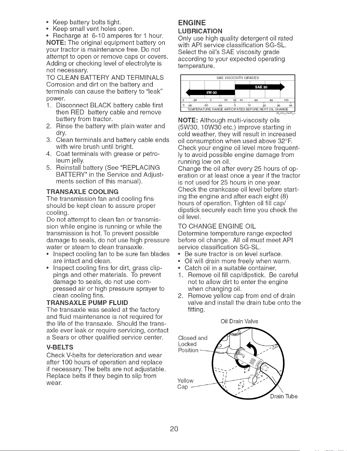
TO CHANGE ENGINE OIL
Determine temperature range expected
before oil change. All oil must meet API
service classification SG-SL
Be sure tractor is on level surface.
Oil will drain more freely when warm.
Catch oil in a suitable container.
1. Remove oil fill cap/dipstick. Be careful
not to allow dirt to enter the engine
when changing oil.
2. Remove yellow cap from end of drain
valve and install the drain tube onto the
fitting.
Oil Drain VaNe
Closed and
Locked
Yellow
Cap
Tube
20
3. Unlock drain valve by pushing inward
slightly and turning counterclockwise.
4. To open, pull out on the drain valve.
5. After oil has drained completely, close
and lock the drain valve by pushing
inward and turning clockwise until the
pin is in the locked position as shown.
6. Remove the drain tube and replace the
cap onto to the end of the drain valve.
7. Refill engine with oil through oil fill dip-
stick tube. Pour slowly. Do not overfill.
For approximate capacity see "PROD-
UCT SPECIFICATIONS" section of this
manual.
8. Use gauge on oil fill cap/dipstick for
checking level. Be sure dipstick cap is
tightened securely for accurate read-
ing. Keep oil at "FULL:' line on dipstick.
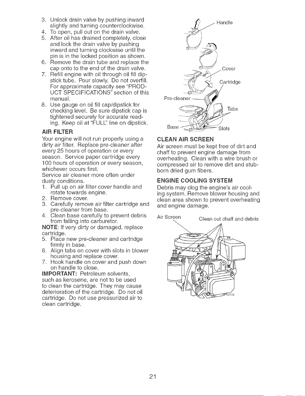
AIR FILTER
Your engine will not run properly using a
dirty air filter. Replace pre-cleaner after
every 25 hours of operation or every
season. Service paper cartridge every
100 hours of operation or every season,
whichever occurs first.
Service air cleaner more often under
dusty conditions.
1. Pull up on air filter cover handle and
rotate towards engine.
2. Remove cover.
3. Carefully remove air filter cartridge and
pre-cleaner from base.
4. Clean base carefully to prevent debris
from falling into carburetor.
NOTE: If very dirty or damaged, replace
cartridge.
5. Place new pre-cleaner and cartridge
firmly in base.
6. Align tabs on cover with slots in blower
housing and replace cover.
7. Hook handle on cover and push down
on handle to close.
IVIPORTANT: Petroleum solvents,
such as kerosene, are not to be used
to clean the cartridge. They may cause
deterioration of the cartridge. Do not oil
cartridge. Do not use pressurized air to
clean cartridge.
__Hand[e
_ Cover
PreocUeane_r_ _
Base_ SUot_,^,s
CLEAN AmR SCREEN
Air screen must be kept free of dirt and
chaff to prevent engine damage from
overheating. Clean with a wire brush or
compressed air to remove dirt and stub-
born dried gum fibers.
ENGINE COOLING SYSTEM
Debris may clog the engine's air cool-
ing system. Remove blower housing and
clean area shown to prevent overheating
and engine damage.
Air Screen
Clean out chaff and debris
21
m'vIUFFLER
Inspect and replace corroded muffler and
spark arrester (if equipped) as it could cre-
ate a fire hazard and/or damage.
SPARK PLUG(S)
Replace spark plug(s) at the beginning
of each mowing season or after every
100 hours of operation, whichever occurs
first. Spark plug type and gap setting are
shown in "PRODUCT SPECIFICATIONS"
section of this manual.
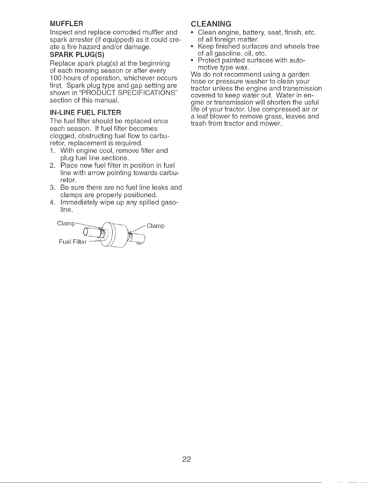
mN-UNE FUEL FmLTER
The fuel filter should be replaced once
each season. If fuel filter becomes
clogged, obstructing fuel flow to carbu-
retor, replacement is required.
1. With engine cool, remove filter and
plug fuel line sections.
2. Place new fuel filter in position in fuel
line with arrow pointing towards carbu-
retor.
3. Be sure there are no fuel line leaks and
clamps are properly positioned.
4. Immediately wipe up any spilled gaso-
line.
CUamp-_-__.__ CUamp
FueUFHter ---__
Clean engine, battery, seat, finish, etc.
of all foreign matter.
Keep finished surfaces and wheels free
of all gasoline, oil, etc.
Protect painted surfaces with auto-
motive type wax.
We do not recommend using a garden
hose or pressure washer to clean your
tractor unless the engine and transmission
covered to keep water out. Water in en-
gine or transmission will shorten the usful
life of your tractor. Use compressed air or
a leaf blower to remove grass, leaves and
trash from tractor and mower.
22
WARNmNG: TO AVOmD SERmOUS mNJURY, BEFORE PERFORMmNG ANYSERVmCE OR ADJUSTMENTS:
1. Depress clutch/brake pedal fully and set parking brake.
2. Place motion control lever in neutral (N) position.
3. Place attachment clutch in "DISENGAGED" position.
4. Turn ignition key to "STOP" and remove key.
5. Make sure the blades and all moving parts have completely stopped.
6. Disconnect spark plug wire from spark plug and place wire where it cannot
come in contact with plug.
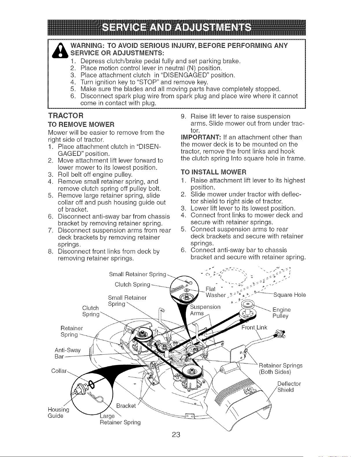
TRACTOR
TO REMOVE MOWER
Mower will be easier to remove from the
right side of tractor.
1. Place attachment clutch in "DISEN-
GAGED" position.
2. Move attachment lift lever forward to
lower mower to its lowest position.
3. Roll belt off engine pulley.
4. Remove small retainer spring, and
remove clutch spring off pulley bolt.
5. Remove large retainer spring, slide
collar off and push housing guide out
of bracket.
6. Disconnect anti-sway bar from chassis
bracket by removing retainer spring.
7. Disconnect suspension arms from rear
deck brackets by removing retainer
springs.
8. Disconnect front links from deck by
removing retainer springs.
Small
Small Retainer
CUutch
8
9. Raise lift lever to raise suspension
arms. Slide mower out from under trac-
tor.
mMPORTANT: If an attachment other than
the mower deck is to be mounted on the
tractor, remove the front links and hook
the clutch spring Into square hole in frame.
TO mNSTALL MOWER
1. Raise attachment lift lever to its highest
position.
2. Slide mower under tractor with deflec-
tor shield to right side of tractor.
3. Lower lift lever to its lowest position.
4. Connect front links to mower deck and
secure with retainer springs.
5. Connect suspension arms to rear
deck brackets and secure with retainer
springs.
6. Connect anti-sway bar to chassis
bracket and secure with retainer spring.
Engine
Pulley
Retainer
Spring
Front Link
Anti-Sway
Bau
Retainer Springs
(Both Sides)
Deflector
Housing
Guide
23
7. Push clutch cable housing guide into
bracket, slide collar onto guide and
secure with large retainer spring.
8. Place flat washer and clutch spring on
idler pulley bolt and secure with small
retainer spring.
9. Install belt onto engine pulley.
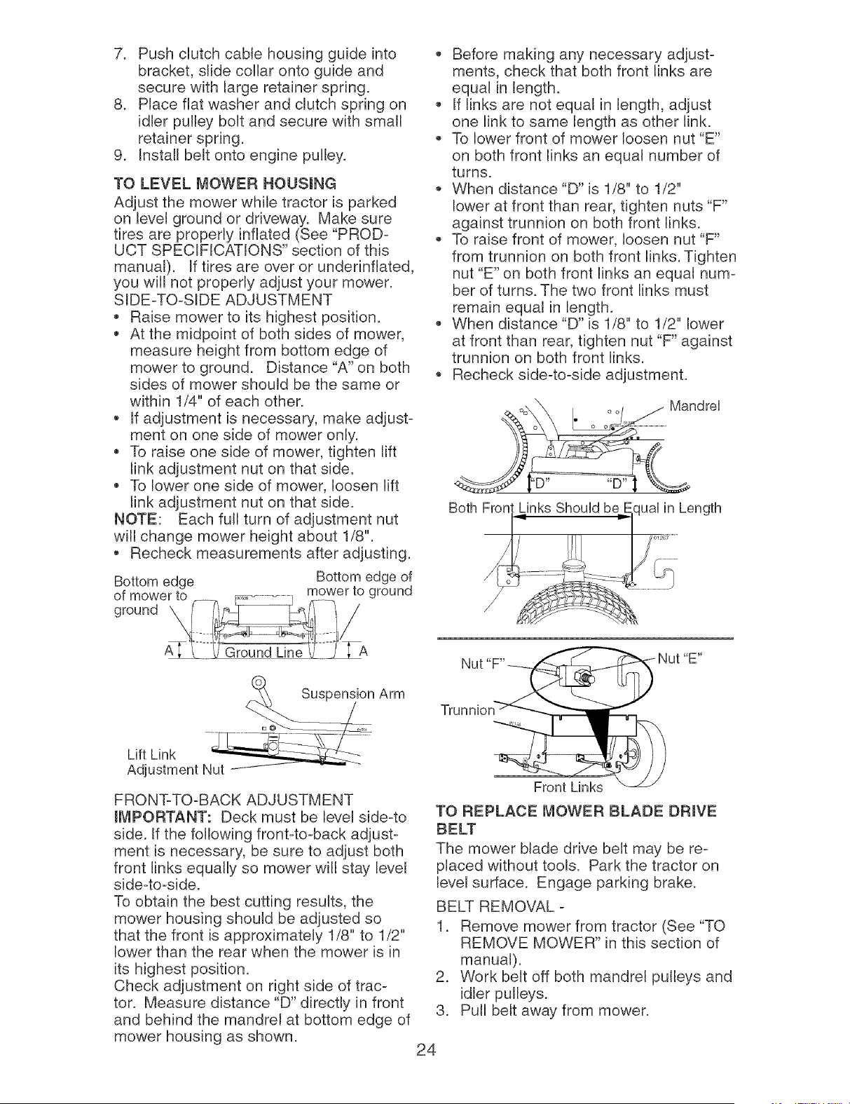
TO LEVEL MOWER HOUSmNG
Adjust the mower while tractor is parked
on level ground or driveway. Make sure
tires are properly inflated (See "PROD-
UCT SPECIFICATIONS" section of this
manual). If tires are over or underinfiated,
you will not properly adjust your mower.
SIDE-TO-SIDE ADJUSTMENT
Raise mower to its highest position.
At the midpoint of both sides of mower,
measure height from bottom edge of
mower to ground. Distance "A" on both
sides of mower should be the same or
within 1/4" of each other.
If adjustment is necessary, make adjust-
ment on one side of mower only.
To raise one side of mower, tighten lift
link adjustment nut on that side.
To lower one side of mower, loosen lift
link adjustment nut on that side.
NOTE: Each full turn of adjustment nut
will change mower height about 1/8".
Recheck measurements after adjusting.
Bottom edge Bottom edge of
of mower to mower to ground
Before making any necessary adjust-
ments, check that both front links are
equal in length.
If links are not equal in length, adjust
one link to same length as other link.
To lower front of mower loosen nut "E"
on both front links an equal number of
turns.
When distance "D" is 1/8" to 1/2"
lower at front than rear, tighten nuts "F"
against trunnion on both front links.
To raise front of mower, loosen nut "F"
from trunnion on both front links. Tighten
nut "E" on both front links an equal num-
ber of turns. The two front links must
remain equal in length.
When distance "D" is 1/8" to 1/2" lower
at front than rear, tighten nut "F" against
trunnion on both front links.
Recheck side-to-side adjustment.
Mandre]
'D.... D"
Both Fron,t Links ShouUd be.E.qual in Length
.......
n Arm
Lift Link .............................
Adjustment Nut
FRONT-TO-BACK ADJUSTMENT
IMPORTANT: Deck must be level side-to
side. If the following front-to-back adjust-
ment is necessary, be sure to adjust both
front links equally so mower will stay level
side-to-side.
To obtain the best cutting results, the
mower housing should be adjusted so
that the front is approximately 1/8" to 1/2"
lower than the rear when the mower is in
its highest position.
Check adjustment on right side of trac-
tor. Measure distance "D" directly in front
and behind the mandrel at bottom edge of
mower housing as shown.
Trunnion
Front Links
TO REPLACE MOWER BLADE DRIVE
BELT
The mower blade drive belt may be re-
placed without tools. Park the tractor on
level surface. Engage parking brake.
BELT REMOVAL -
1. Remove mower from tractor (See "TO
REMOVE MOWER" in this section of
manual).
2. Work belt off both mandrel pulleys and
idler pulleys.
3. Pull belt away from mower.
24
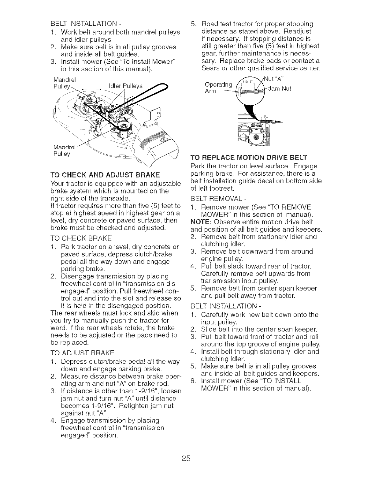
BELT INSTALLATION -
1. Work belt around both mandrel pulleys
and idler pulleys
2. Make sure belt is in all pulley grooves
and inside all belt guides.
3. Install mower (See "To Install Mower"
in this section of this manual).
Mandrel
Idler
Pulley
TO CHECK AND ADJUST BRAKE
Your tractor is equipped with an adjustable
brake system which is mounted on the
right side of the transaxle.
If tractor requires more than five (5) feet to
stop at highest speed in highest gear on a
level, dry concrete or paved surface, then
brake must be checked and adjusted.
TO CHECK BRAKE
1. Park tractor on a level, dry concrete or
paved surface, depress clutch/brake
pedal all the way down and engage
parking brake.
2. Disengage transmission by placing
freewheel control in "transmission dis-
engaged" position. Pull freewheel con-
trol out and into the slot and release so
it is held in the disengaged position.
The rear wheels must lock and skid when
you try to manually push the tractor for-
ward. If the rear wheels rotate, the brake
needs to be adjusted or the pads need to
be replaced.
TO ADJUST BRAKE
1. Depress clutch/brake pedal all the way
down and engage parking brake.
2. Measure distance between brake oper-
ating arm and nut "A" on brake rod.
3. If distance is other than 1-9/16", loosen
jam nut and turn nut "A" until distance
becomes 1-9/16". Retighten jam nut
against nut "A".
4. Engage transmission by placing
freewheel control in "transmission
engaged" position.
,
Road test tractor for proper stopping
distance as stated above. Readjust
if necessary. If stopping distance is
still greater than five (5) feet in highest
gear, further maintenance is neces-
sary. Replace brake pads or contact a
Sears or other qualified service center.
TO REPLACE I_OTmON DRmVE BELT
Park the tractor on level surface. Engage
parking brake. For assistance, there is a
belt installation guide decal on bottom side
of left footrest.
BELT REMOVAL -
1. Remove mower (See "TO REMOVE
MOWER" in this section of manual).
NOTE: Observe entire motion drive belt
and position of all belt guides and keepers.
2. Remove belt from stationary idler and
clutching idler.
3. Remove belt downward from around
engine pulley.
4. Pull belt slack toward rear of tractor.
Carefully remove belt upwards from
transmission input pulley.
5. Remove belt from center span keeper
and pull belt away from tractor.
BELT INSTALLATION -
1. Carefully work new belt down onto the
input pulley.
2. Slide belt into the center span keeper.
3. Pull belt toward front of tractor and roll
around the top groove of engine pulley.
4. Install belt through stationary idler and
clutching idler.
5. Make sure belt is in all pulley grooves
and inside all belt guides and keepers.
6. Install mower (See "TO INSTALL
MOWER" in this section of manual).
25
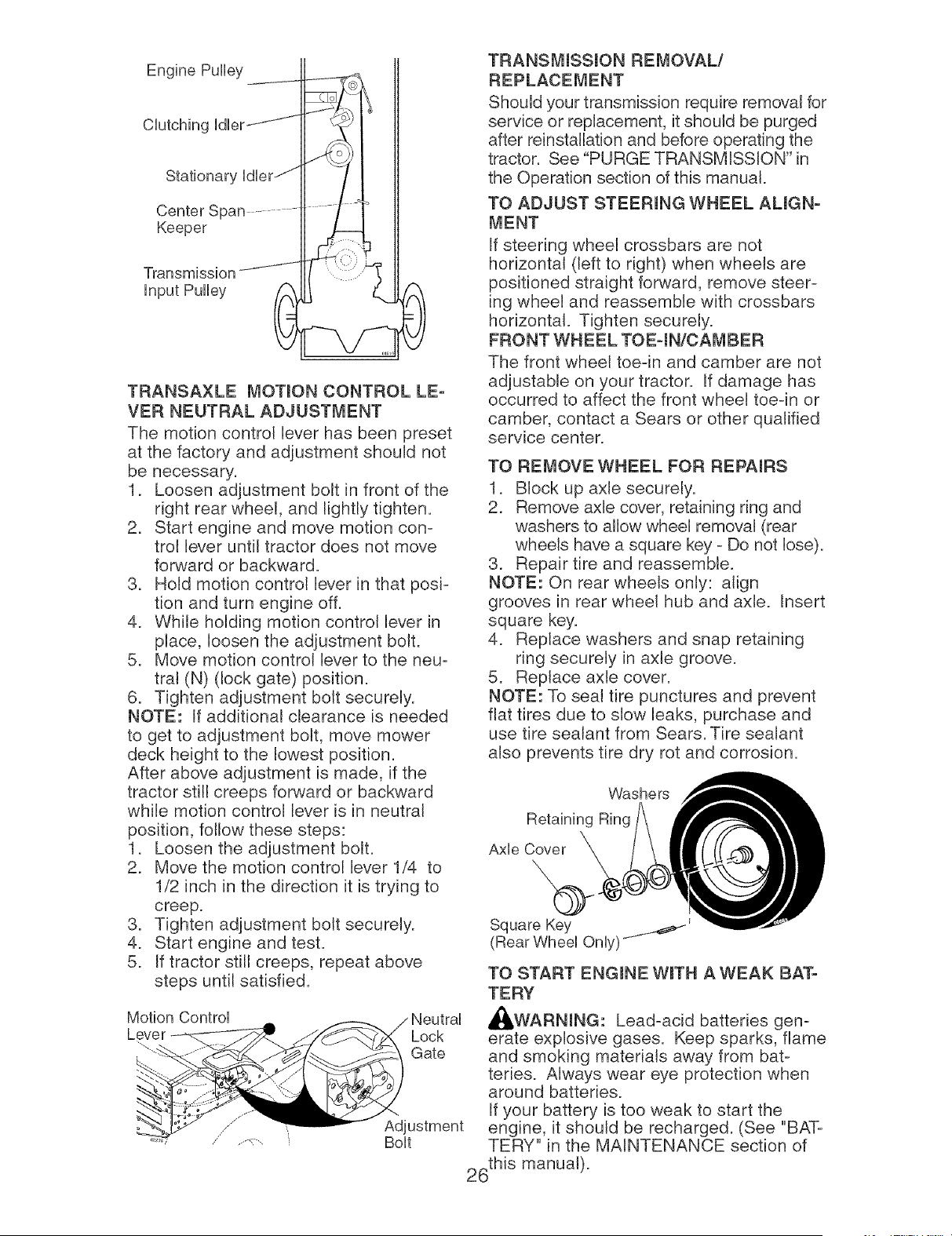
Engine Pulley .... _
Clutching Idler _
Keeper
Transm,ssion.......
input Pulley
TRANSAXLE MOTmON CONTROL LE-
VER NEUTRAL ADJUSTMENT
The motion control lever has been preset
at the factory and adjustment should not
be necessary.
1. Loosen adjustment bolt in front of the
right rear wheel, and lightly tighten.
2. Start engine and move motion con-
trol lever until tractor does not move
forward or backward.
3. Hold motion control lever in that posi-
tion and turn engine off.
4. While holding motion control lever in
place, loosen the adjustment bolt.
5. Move motion control lever to the neu-
trat (N) (lock gate) position.
6. Tighten adjustment bolt securely.
NOTE: If additional clearance is needed
to get to adjustment bolt, move mower
deck height to the lowest position.
After above adjustment is made, if the
tractor still creeps forward or backward
while motion control lever is in neutral
position, follow these steps:
1. Loosen the adjustment bolt.
2. Move the motion control lever 1/4 to
1/2 inch in the direction it is trying to
creep.
3. Tighten adjustment bolt securely.
4. Start engine and test.
5. If tractor still creeps, repeat above
steps until satisfied.
Motion Control
Lever
-,..
Lock
Gate
Bolt
TRANSMmSSmON REMOVAL/
REPLACErvIENT
Shoutd your transmission require removal for
service or replacement, it should be purged
after reinstallation and before operating the
tractor. See "PURGE TRANSMISSION" in
the Operation section of this manual.
TO ADJUST STEERmNG WHEEL AUGN-
MENT
If steering wheel crossbars are not
horizontal (left to right) when wheels are
positioned straight forward, remove steer-
ing wheel and reassemble with crossbars
horizontal. Tighten securely.
FRONT WHEEL TOEqN/CAMBER
The front wheel toe-in and camber are not
adjustable on your tractor. If damage has
occurred to affect the front wheel toe-in or
camber, contact a Sears or other qualified
service center.
TO REMOVE WHEEL FOR REPAIRS
1. Block up axle securely.
2. Remove axle cover, retaining ring and
washers to allow wheel removal (rear
wheels have a square key - Do not lose).
3. Repair tire and reassemble.
NOTE: On rear wheels only: align
grooves in rear wheel hub and axle. Insert
square key.
4. Replace washers and snap retaining
ring securely in axle groove.
5. Replace axle cover.
NOTE: To seal tire punctures and prevent
flat tires due to slow leaks, purchase and
use tire sealant from Sears. Tire sealant
also prevents tire dry rot and corrosion.
Washers
Retaining Ring
Axle Cover
Square Key
(Rear Wheel Only)
TO START ENGmNE WroTH A WEAK BAT-
TERY
,_WARNmNG: Lead-acid batteries gen-
erate explosive gases. Keep sparks, flame
and smoking materials away from bat-
teries. Always wear eye protection when
around batteries.
If your battery is too weak to start the
engine, it should be recharged. (See "BAT-
TERY" in the MAINTENANCE section of
26this manual).
If "jumper cables" are used for emergency
starting, follow this procedure:
mMPORTANT: Your tractor is equipped
with a 12 volt system. The other vehicle
must also be a 12 volt system. Do not use
your tractor battery to start other vehicles.
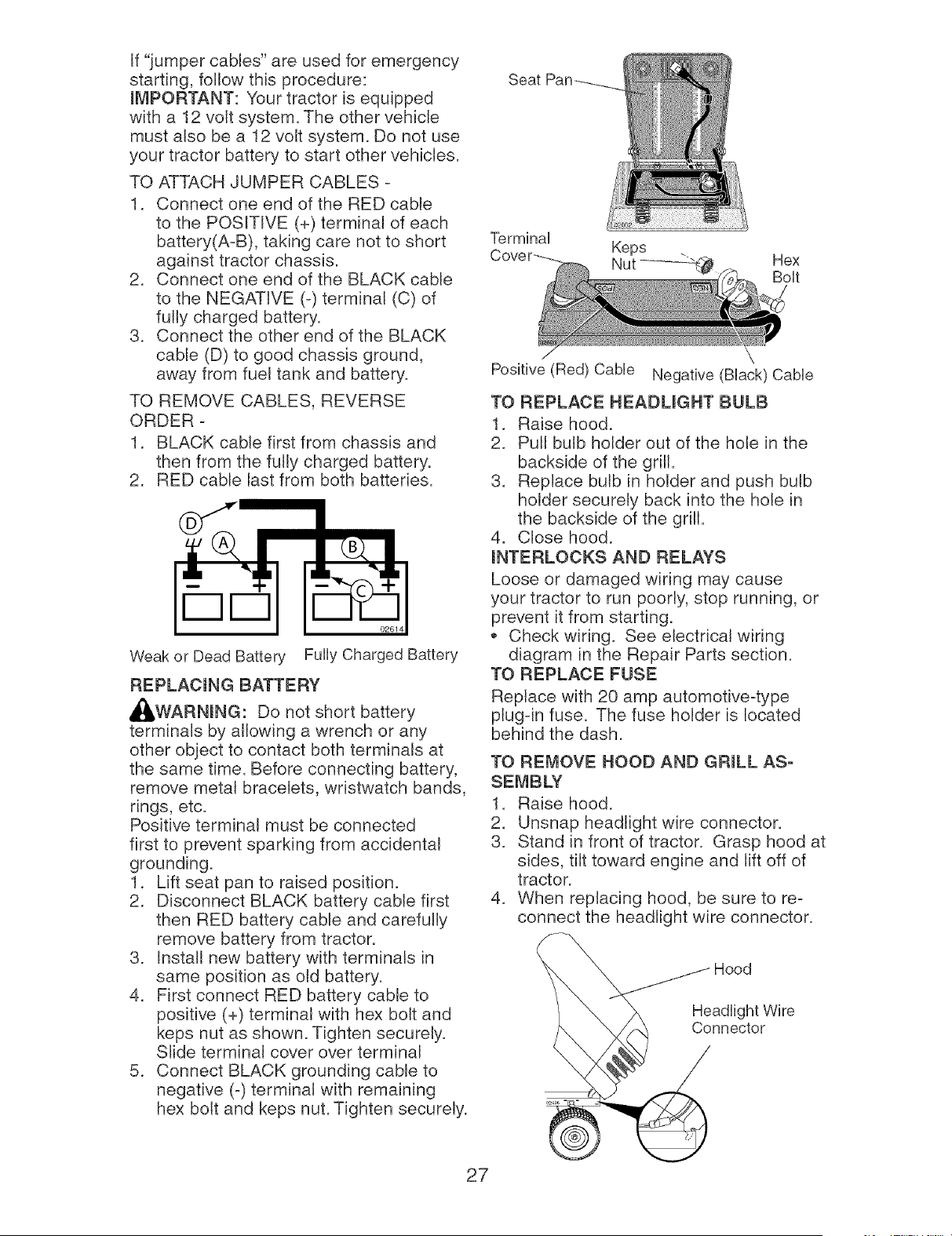
Seat
TO ATTACH JUMPER CABLES -
1. Connect one end of the RED cable
to the POSITIVE (+) terminal of each
battery(A-B), taking care not to short
against tractor chassis.
2. Connect one end of the BLACK cable
to the NEGATIVE (-) terminal (C) of
fully charged battery.
3. Connect the other end of the BLACK
cable (D) to good chassis ground,
away from fuel tank and battery.
Terminal
Keps
Nut _ Hex
Bolt
Positive (Red) Cable Negative (Black) Cable
TO REMOVE CABLES, REVERSE
ORDER -
1. BLACK cable first from chassis and
then from the fully charged battery.
2. RED cable last from both batteries.
02614
Weak or Dead Battery Fully Charged Battery
REPLACmNG BATTERY
,_WARNmNG: Do not short battery
terminals by allowing a wrench or any
other object to contact both terminals at
the same time. Before connecting battery,
remove metal bracelets, wristwatch bands,
rings, etc.
Positive terminal must be connected
first to prevent sparking from acddental
grounding.
1. Lift seat pan to raised position.
2. Disconnect BLACK battery cable first
then RED battery cable and carefully
remove battery from tractor.
3. Install new battery with terminals in
same position as old battery.
4. First connect RED battery cable to
positive (+) terminal with hex bolt and
keps nut as shown. Tighten securely.
Slide terminal cover over terminal
5. Connect BLACK grounding cable to
negative (-) terminal with remaining
hex bolt and keps nut. Tighten securely.
27
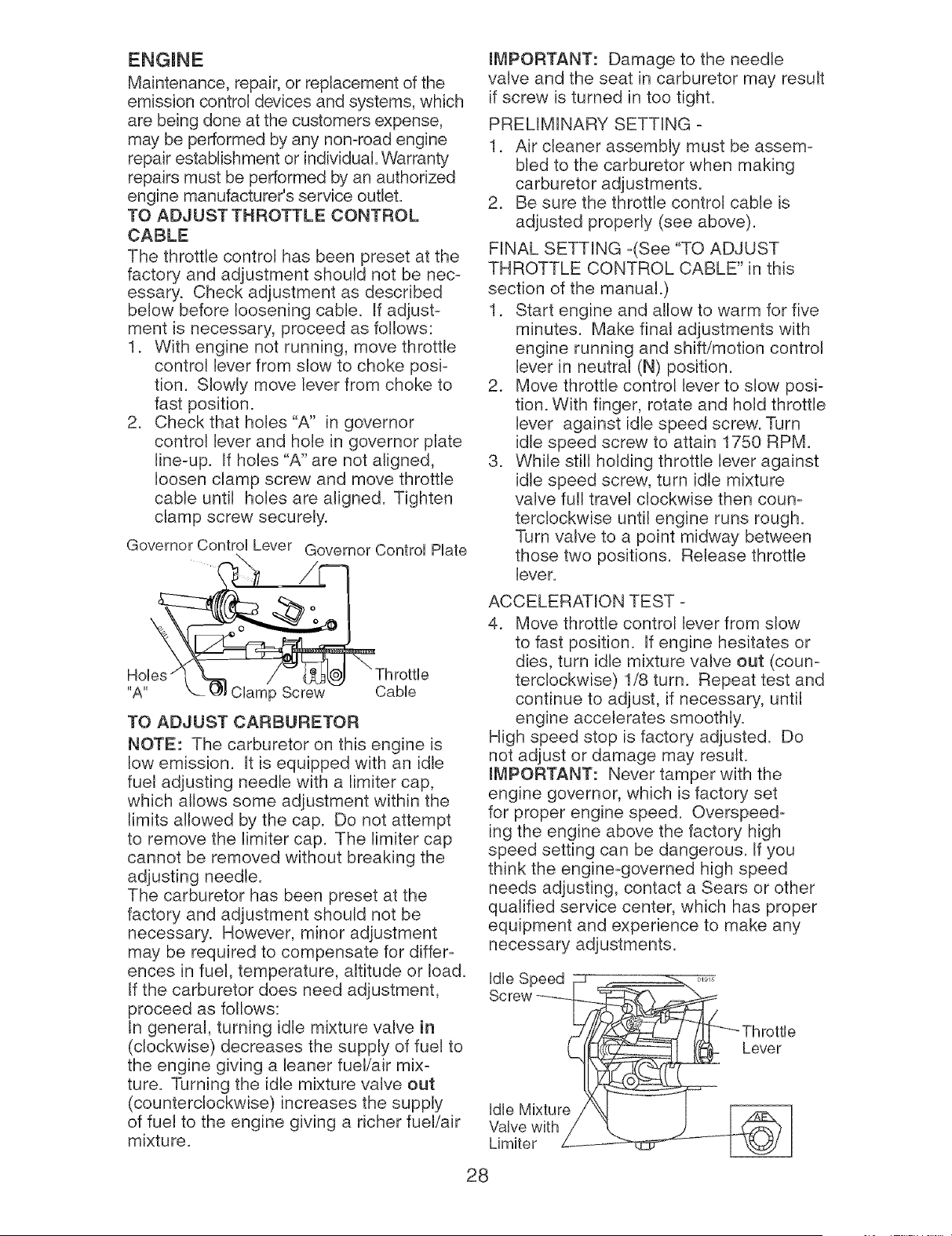
TO REPLACE HEADUGHT BULB
1. Raise hood.
2. Pull bulb holder out of the hole in the
backside of the grill.
3. Replace bulb in holder and push bulb
holder securely back into the hole in
the backside of the grill.
4. Close hood.
mNTERLOCKS AND RELAYS
Loose or damaged wiring may cause
your tractor to run poorly, stop running, or
prevent it from starting.
,_ Check wiring. See electrical wiring
diagram in the Repair Parts section.
TO REPLACE FUSE
Replace with 20 amp automotive-type
plug-in fuse. The fuse holder is located
behind the dash.
TO REMOVE HOOD AND GRmLL AS-
SEMBLY
1. Raise hood.
2. Unsnap headlight wire connector.
3. Stand in front of tractor. Grasp hood at
sides, tilt toward engine and lift off of
tractor.
4. When replacing hood, be sure to re-
connect the headlight wire connector.
\
\
\
@
Hood
Maintenance,repair,orreplacementof the
emissioncontroldevicesandsystems,which
are beingdoneat thecustomersexpense,
maybe performedbyanynon-roadengine
repairestablishmentorindividual.Warranty
repairsmustbeperformedbyanauthorized
enginemanufacturer'sserviceoutlet.
TOADJUSTTHROTTLECONTROL
CABLE
The throttle control has been presetat the
factoryand adjustmentshould not be nec-
essary. Checkadjustmentas described
below beforelooseningcable. If adjust-
ment is necessary,proceedas follows:
1. With engine not running,move throttle
control leverfromslow to choke posi-
tion. Slowly moveleverfrom choketo
fast position.
2. Checkthat holes"A" in governor
control leverand hole in governorplate
line-up. If holes"A" are not aligned,
loosenclampscrew and movethrottle
cable until holesare aligned. Tighten
clampscrew securely.
GovernorControlLever GovernorControlPlate
,-!I
Hobs
"A" Clamp Screw Cable
TO ADJUST CARBURETOR
NOTE: The carburetor on this engine is
low emission. It is equipped with an idle
fuel adjusting needle with a limiter cap,
which allows some adjustment within the
limits allowed by the cap. Do not attempt
to remove the limiter cap. The limiter cap
cannot be removed without breaking the
adjusting needle.
The carburetor has been preset at the
factory and adjustment should not be
necessary. However, minor adjustment
may be required to compensate for differ-
ences in fuel, temperature, altitude or load.
If the carburetor does need adjustment,
proceed as follows:
In general, turning idle mixture valve in
(clockwise) decreases the supply of fuel to
the engine giving a leaner fuel/air mix-
ture. Turning the idle mixture valve out
(counterclockwise) increases the supply
of fuel to the engine giving a richer fuel/air
mixture.
iMPORTANT: Damage to the needle
valve and the seat in carburetor may result
if screw is turned in too tight.
PRELIMINARY SETTING -
1. Air cleaner assembly must be assem-
bled to the carburetor when making
carburetor adjustments.
2. Be sure the throttle control cable is
adjusted properly (see above).
FINAL SETTING -(See "TO ADJUST
THROTTLE CONTROL CABLE" in this
section of the manual.)
1. Start engine and allow to warm for five
minutes. Make final adjustments with
engine running and shift/motion control
lever in neutral (N) position.
2. Move throttle control lever to slow posi-
tion. With finger, rotate and hold throttle
lever against idle speed screw. Turn
idle speed screw to attain 1750 RPM.
3. While still holding throttle lever against
idle speed screw, turn idle mixture
valve full travel clockwise then coun-
terclockwise until engine runs rough.
Turn valve to a point midway between
those two positions. Release throttle
lever.
ACCELERATION TEST -
4. Move throttle control lever from slow
to fast position. If engine hesitates or
dies, turn idle mixture valve out (coun-
terclockwise) 1/8 turn. Repeat test and
continue to adjust, if necessary, until
engine accelerates smoothly.
High speed stop is factory adjusted. Do
not adjust or damage may result.
iMPORTANT: Never tamper with the
engine governor, which is factory set
for proper engine speed. Overspeed-
ing the engine above the factory high
speed setting can be dangerous. If you
think the engine-governed high speed
needs adjusting, contact a Sears or other
qualified service center, which has proper
equipment and experience to make any
necessary adjustments.
Idle Speed
Screw
Lever
Idle Mixture
Valve with
Limiter
28
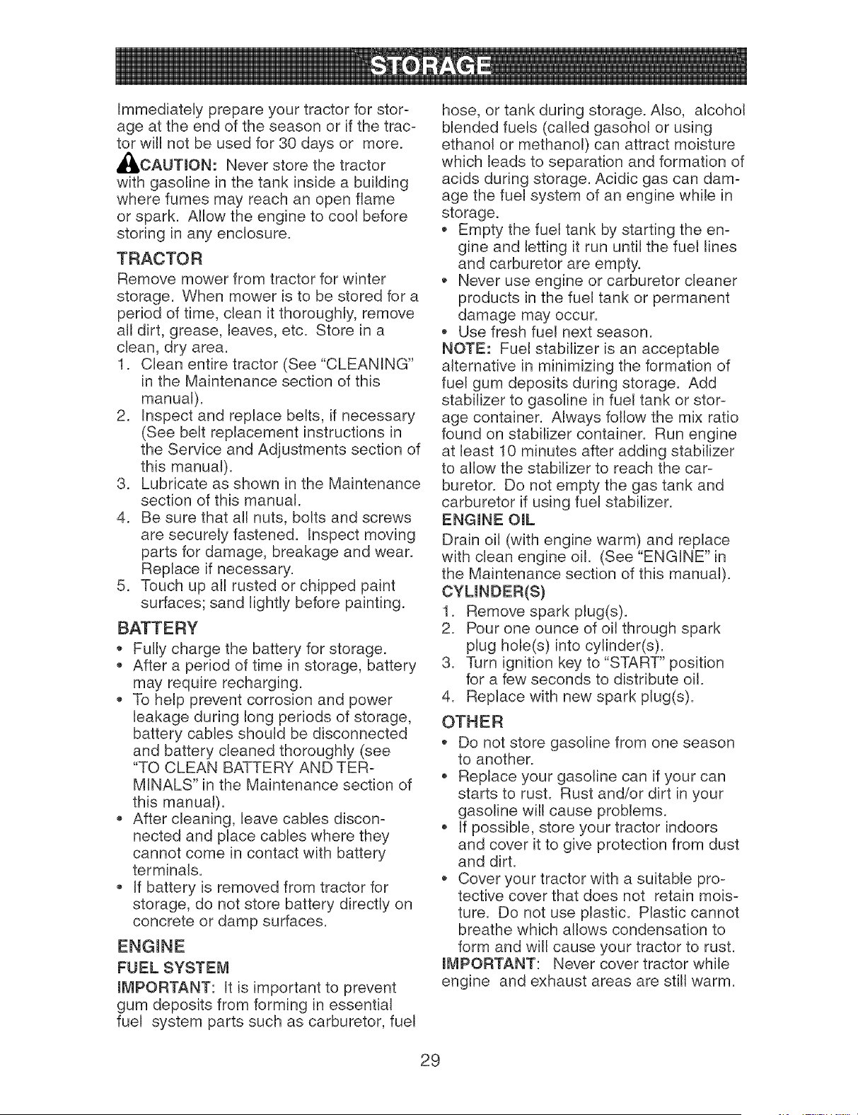
Immediately prepare your tractor for stor-
age at the end of the season or if the trac-
tor will not be used for 30 days or more.
_I, CAUTmON: Never store the tractor
with gasoline in the tank inside a building
where fumes may reach an open flame
or spark. Allow the engine to cool before
storing in any enclosure.
TRACTOR
Remove mower from tractor for winter
storage. When mower is to be stored for a
period of time, clean it thoroughly, remove
all dirt, grease, leaves, etc. Store in a
clean, dry area.
1. Clean entire tractor (See "CLEANING"
in the Maintenance section of this
manual).
2. Inspect and replace belts, if necessary
(See belt replacement instructions in
the Service and Adjustments section of
this manual).
3. Lubricate as shown in the Maintenance
section of this manual.
4. Be sure that all nuts, bolts and screws
are securely fastened. Inspect moving
parts for damage, breakage and wear.
Replace if necessary.
5. Touch up all rusted or chipped paint
surfaces; sand lightly before painting.
Fully charge the battery for storage.
After a period of time in storage, battery
may require recharging.
To help prevent corrosion and power
leakage during long periods of storage,
battery cables should be disconnected
and battery cleaned thoroughly (see
"TO CLEAN BATTERY AND TER-
MINALS" in the Maintenance section of
this manual).
After cleaning, leave cables discon-
nected and place cables where they
cannot come in contact with battery
terminals.
If battery is removed from tractor for
storage, do not store battery directly on
concrete or damp surfaces.
FUEL SYSTEM
mI_,4PORTANT: It is important to prevent
gum deposits from forming in essential
fuel system parts such as carburetor, fuel
hose, or tank during storage. Also, alcohol
blended fuels (called gasohol or using
ethanol or methanol) can attract moisture
which leads to separation and formation of
acids during storage. Acidic gas can dam-
age the fuel system of an engine while in
storage.
Empty the fuel tank by starting the en-
gine and letting it run until the fuel lines
and carburetor are empty.
Never use engine or carburetor cleaner
products in the fuel tank or permanent
damage may occur.
Use fresh fuel next season.
NOTE: Fuel stabilizer is an acceptable
alternative in minimizing the formation of
fuel gum deposits during storage. Add
stabilizer to gasoline in fuel tank or stor-
age container. Always follow the mix ratio
found on stabilizer container. Run engine
at least 10 minutes after adding stabilizer
to allow the stabilizer to reach the car-
buretor. Do not empty the gas tank and
carburetor if using fuel stabilizer.
ENG(NE O(L
Drain oil (with engine warm) and replace
with clean engine oil. (See "ENGINE" in
the Maintenance section of this manual).
1. Remove spark plug(s).
2. Pour one ounce of oil through spark
plug hole(s) into cylinder(s).
3. Turn ignition key to "START" position
for a few seconds to distribute oil.
4. Replace with new spark plug(s).
OTHER
Do not store gasoline from one season
to another.
Replace your gasoline can if your can
starts to rust. Rust and/or dirt in your
gasoline will cause problems.
If possible, store your tractor indoors
and cover it to give protection from dust
and dirt.
Cover your tractor with a suitable pro-
tective cover that does not retain mois-
ture. Do not use plastic. Plastic cannot
breathe which allows condensation to
form and will cause your tractor to rust.
mMPORTANT: Never cover tractor while
engine and exhaust areas are still warm.
29
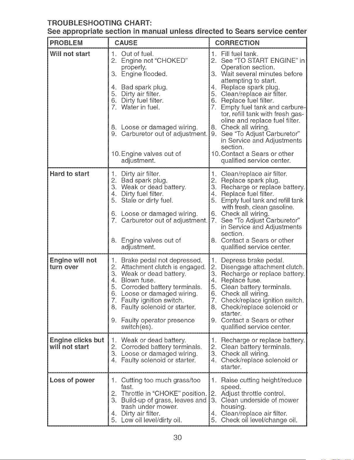
TROUBLESHOOTmNG CHART:
See appropriate section in manuam unmess directed to Sears service center
PROBLEM CAUSE CORRECTmON
Will not start
Hard to start
Engine will not
turn over
Engine clicks but
wiii not start
Loss of power
1. Out of fuel.
2. Engine not "CHOKED"
properly.
3. Engine flooded.
4. Bad spark plug.
5. Dirty air filter.
6. Dirty fuel filter.
7. Water in fuel.
8. Loose or damaged wiring.
9. Carburetor out of adjustment.
10. Engine valves out of
adjustment.
1. Dirty air filter.
2. Bad spark plug.
3. Weak or dead battery.
4. Dirty fuel filter.
5. Stale or dirty fuel.
6. Loose or damaged wiring.
7. Carburetor out of adjustment.
8. Engine valves out of
adjustment.
1. Brake pedal not depressed.
2. Attachment clutch is engaged.
3. Weak or dead battery.
4. Blown fuse.
5. Corroded battery terminals.
6. Loose or damaged wiring.
7. Faulty ignition switch.
8. Faulty solenoid or starter.
9. Faulty operator presence
switch(es).
1. Weak or dead battery.
2. Corroded battery terminals.
3. Loose or damaged wiring.
4. Faulty solenoid or starter.
1. Cutting too much grass/too
fast.
2. Throttle in "CHOKE" position.
3. Build-up of grass, leaves and
trash under mower.
4. Dirty air filter.
5. Low oil level/dirty oil.
1. Fill fuel tank.
2. See "TO START ENGINE" in
Operation section.
3. Wait several minutes before
attempting to start.
4. Replace spark plug.
5. Clean/replace air filter.
6. Replace fuel filter.
7. Empty fuel tank and carbure-
tor, refill tank with fresh gas-
oline and replace fuel filter.
8. Check all wiring.
9. See "To Adjust Carburetor"
in Service and Adjustments
section.
10. Contact a Sears or other
qualified service center.
1. Clean/replace air filter.
2. Replace spark plug.
3. Recharge or replace battery.
4. Replace fuel filter.
5. Empty fuel tank and refill tank
with fresh, clean gasoline.
6. Check all wiring.
7. See "To Adjust Carburetor"
in Service and Adjustments
section.
8. Contact a Sears or other
qualified service center.
1. Depress brake pedal.
2. Disengage attachment clutch.
3. Recharge or replace battery.
4. Replace fuse.
5. Clean battery terminals.
6. Check all wiring.
7. Check/replace ignition switch.
8. Check/replace solenoid or
starter.
9. Contact a Sears or other
qualified service center.
1. Recharge or replace battery.
2. Clean battery terminals.
3. Check all wiring.
4. Check/replace solenoid or
starter.
1. Raise cutting height/reduce
speed.
2. Adjust throttle control.
3. Clean underside of mower
housing.
4. Clean/replace air filter.
5. Check oil leveL/change oil.
30

TROUBLESHOOTmNG CHART:
See appropriate section in manuam unmess directed to Sears service center
_ROBLEi_ CORRECTmONCAUSE
6. Faulty spark plug.
7. Dirty fuel filter.
8. Stale or dirty fuel.
9. Water in fuel.
Loss of power
(continued)
Excessive
vibration
Engine continues
to run when
operator leaves
seat with
attachment
clutch engaged
Poor cut - uneven
Mower blades will
not rotate
Poor grass
discharge
10.Spark plug wire loose.
11. Dirty engine air screen/fins.
12. Dirty/clogged muffler.
13. Loose or damaged wiring.
14. Carburetor out of adjustment
15. Engine valves out of
adjustment.
1. Worn, bent or loose blade.
2. Bent blade mandrel.
3. Loose/damaged part(s).
1. Faulty operator=safety
presence control system.
1. Worn, bent or loose blade.
2. Mower deck not level.
3. Buildup of grass, leaves, and
trash under mower.
4. Bent blade mandrel.
5. Clogged mower deck vent
from build=up of grass, leaves,
and trash around mandrels.
1. Obstruction in clutch
mechanism.
2. Worn/damaged mower drive
belt.
3. Frozen idler pulley.
4. Frozen blade mandrel.
1. Engine speed too slow.
2. Travel speed too fast.
6. Clean and regap or change
spark plug.
7. Replace fuel filter.
8. Empty fuel tank and refill tank
with fresh, clean gasoline.
9. Empty fuel tank and carbure=
tor, refill tank with fresh gas=
oline and replace fuel filter.
10. Connect and tighten spark
plug wire.
11. Clean engine air screen/fins.
12. Clean/replace muffler.
13.Check all wiring.
14. See "To Adjust Carburetor"
in Service and Adjustments
section.
15. Contact a Sears or other
qualified service center.
1. Replace blade. Tighten blade
bolt.
2. Contact a Sears or other
qualified service center.
3. Tighten loose part(s).
Replace damaged parts.
,
Check wiring, switches and
connections. If not corrected
contact a Sears or other
qualified service center.
1. Replace blade. Tighten blade
bolt.
2. Level mower deck.
3. Clean underside of mower
housing.
4. Contact a Sears or other
qualified service center.
5. Clean around mandrels to
open vent holes.
1. Remove obstruction.
2. Replace mower drive belt.
3. Replace idler pulley.
4. Contact a Sears or other
qualified service center.
1. Place throttle control in
"FAST" position.
2. Shift to slower speed.
31
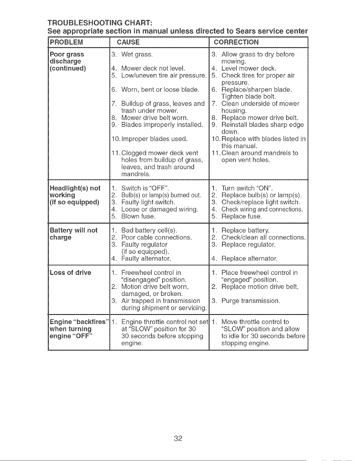
TROUBLESHOOTmNG CHART:
See appropriate section in marluam unmess directed to Sears service center
PROBLEi_I CORRECTmON
Poor grass
discharge
i(continued)
iHeadiight(s) not
working
i(if so equipped)
iBattery wiii not
charge
Loss of drive
iEngine "backfires"
when turning
engine "OFF"
CAUSE
3. Wet grass.
4. Mower deck not level.
5. Low/uneven tire air pressure.
6. Worn, bent or loose blade.
7. Buildup of grass, leaves and
trash under mower.
8. Mower drive belt worn.
9. Blades improperly installed.
10. Improper blades used.
11.
Clogged mower deck vent
holes from buildup of grass,
leaves, and trash around
mandrels.
1. Switch is "OFF".
2. Bulb(s) or lamp(s) burned out.
3. Faulty light switch.
4. Loose or damaged wiring.
5. Blown fuse.
1. Bad battery cell(s).
2. Poor cable connections.
3. Faulty regulator
(if so equipped).
4. Faulty alternator.
1. Freewheel control in
"disengaged" position.
2. Motion drive belt worn,
damaged, or broken.
3. Air trapped in transmission
during shipment or servicing.
.
Engine throttle control not set
at "SLOW" position for 30
30 seconds before stopping
engine.
3. Allow grass to dry before
mowing.
4. Level mower deck.
5. Check tires for proper air
pressure.
6. Replace/sharpen blade.
Tighten blade bolt.
7. Clean underside of mower
housing.
8. Replace mower drive belt.
9. Reinstall blades sharp edge
down.
10. Replace with blades listed in
this manual.
11. Glean around mandrels to
open vent holes.
1. Turn switch "ON".
2. Replace bulb(s) or lamp(s).
3. ChecWreplace light switch.
4. Check wiring and connections.
5. Replace fuse.
1. Replace battery.
2. Check/clean all connections.
3. Replace regulator.
4. Replace alternator.
1. Place freewheel control in
"engaged" position.
2. Replace motion drive belt.
3. Purge transmission.
. Move throttle control to
"SLOW" position and allow
to idle for 30 seconds before
stopping engine.
32
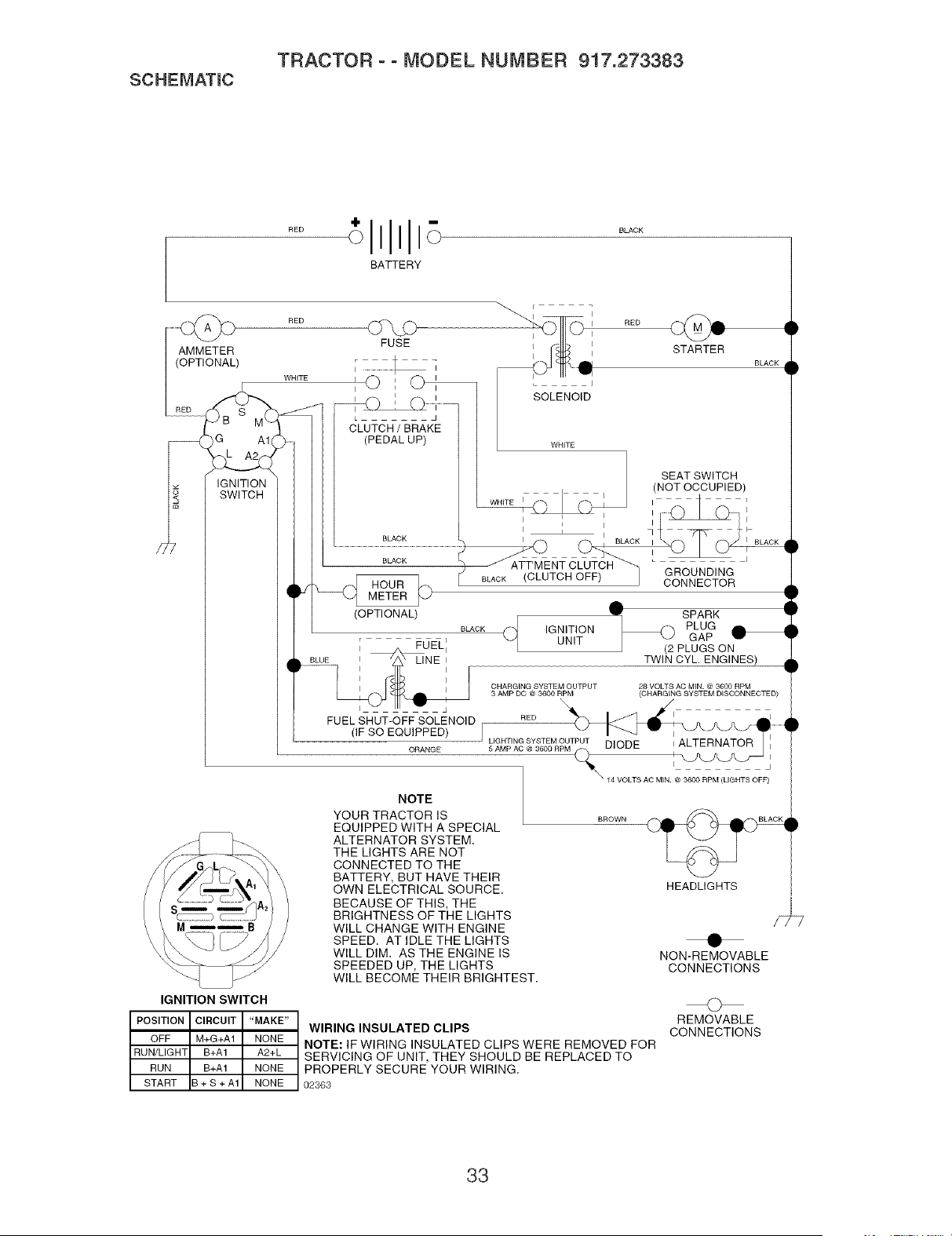
SCHEMATmC
TRACTOR ooMODEL NUMBER 917.273383
BATTERY
AMMETER
(OPTIONAL)
--_ )G A1
IGNITION
SWITCH
RED
WHITE
g
FUSE
I I I
,O,C
i I i
CLUTCH / BRAKE
(PEDAL UP)
BLACK
(OPTIONAL)
___ RED
STARTER BLACK
SOLENOID
WHITE
SEAT SWITCH
i (NOT OCCUPIED)
I
WHITE
I .......... I
i I
I _ I • F
GROUNDING
CONNECTOR
_lW SPARK 1
I
BLACK _._ IGNITION _k_ PLUG
r , UNIT GAP HI
I //_ FUELI (2 PLUGS ON
k BLUE I LINE I TWIN CYL ENGINES)
dh
' ' , qF
I I
_\_ CHARG,NG SYSTEM OUTPUT 28 VOLTS AC MIN. @ 3600 RPM
3 AMP DC @ 3600 RPM (CHARGING SYSTEM DISCONNECTED)
FUEL SHUT-OFF SOLENOID RED
(IF SO EQUIPPED) J L'GMHTINcG_Y3SToEMOMUT_T DIODE ,ALTERNATOR
ORANGE _ I _L_--J j
NOTE
YOUR TRACTOR IS
EQUIPPED WITH A SPECIAL
ALTERNATOR SYSTEM.
THE LIGHTS ARE NOT
CONNECTED TO THE
BATTERY, BUT HAVE THEIR
OWN ELECTRICAL SOURCE.
BECAUSE OF THIS, THE
BRIGHTNESS OF THE LIGHTS
WILL CHANGE WITH ENGINE
SPEED. AT IDLE THE LIGHTS
WILL DIM. AS THE ENGINE IS
SPEEDED UP, THE LIGHTS
WILL BECOME THEIR BRIGHTEST.
\ 14 VOLTS AC MIN. @ 3600 RPM (LIGHTS OFF)
BROWN
HEADLIGHTS
NON-REMOVABLE
CONNECTIONS
IGNITION SWITCH
POSITION CIRCUIT "MAKE"
OFF M+G+A1 NONE
RUN/LIGHT B+A1 A2+L
RUN B+A1 NONE
START B+S+A1 NONE
WIRING INSULATED CLIPS
NOTE: IF WIRING INSULATED CLIPS WERE REMOVED FOR
SERVICING OF UNIT, THEY SHOULD BE REPLACED TO
PROPERLY SECURE YOUR WIRING.
02363
O
REMOVABLE
CONNECTIONS
33
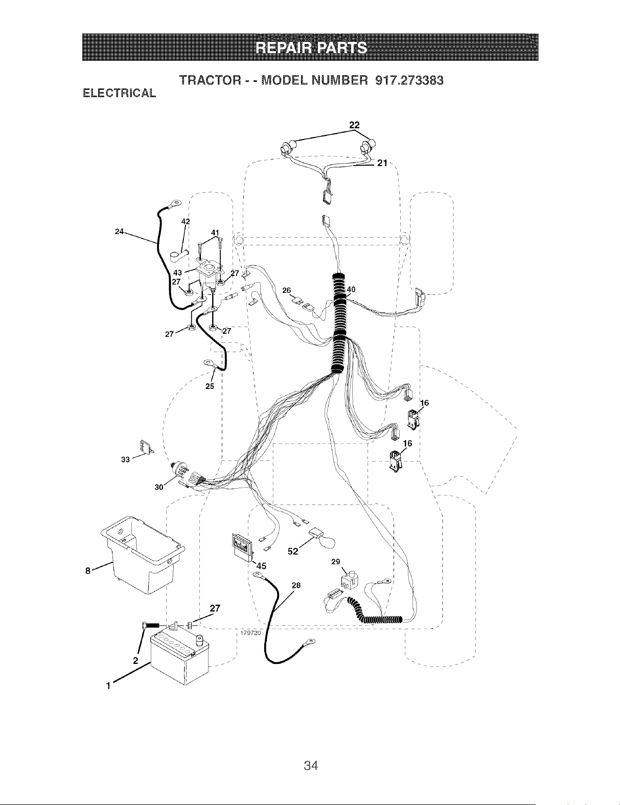
ELECTRmCAL
TRACTOR ° ° MODEL NUMBER 917.273383
I
42
I
/I
26
i
\
\
33
I
1
i
s
!
/
\/
\
/!
!
//
!
34

ELECTRmCAL
TRACTOR o o MODEL NUMBER 917.273383
KEY PART
NO. NO. DESCRmPTmON
1 163465 Battery
2 74760412 Bolt Hex Hd 1/4-20 unc x 3/4
8 176689 Box Battery Fender
16 176138 Switch, hterlock
21 183759 Harness Asm Light W/4152j
22 4152J Bulb Light #1156
24 4799J Cable Battery 6 Ga, 11" red
25 146147 Cable Battery 6 Ga, w/16 wire red
26 175158 Fuse 20 AMP
27 73510400 Nut Keps Hex 1/4-20 unc
28 4207J Cable Ground 6 Ga, 12" black
29 121305X Switch Hunger Nc Gray
30 175566 Switch Hgn
33 140403 Key Hgn
40 179720 Harness Hgn
41 71110408 BoIt BIk, Fin Hex 1/4-20 unc x 1/2
42 131563 Cover Terminal Red
43 178861 SoIenoid
45 121433X Ammeter Rectangular 6 Amp
52 141940 Protection Wire Loop
90 180449 Cover Battery Fender
NOTE: All component dimensions given in U,S, inches
1 inch = 25,4 mm
35
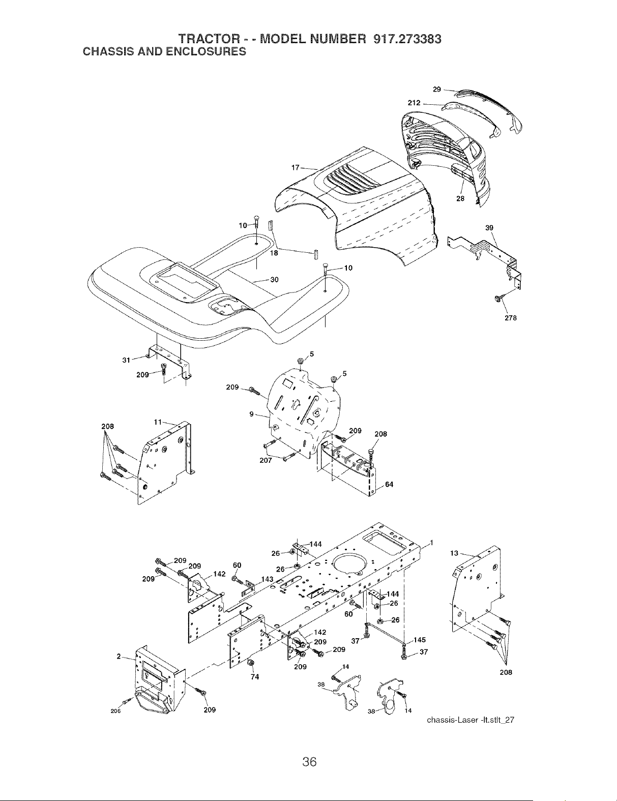
TRACTOR ° o MODEL NUMBER 917.273383
CHASSmSAND ENCLOSURES
/
28
39
278
208
31
207
@/5
209
208
206
209
.209
209
209
6O
74
209
6O
_209 37
_209
14
3_ 38_114
208
chassis-Laser-It.stlt 27
36

TRACTOR o o MODEL NUMBER 917.273383
CHASSmS AND ENCLOSURES
KEY PART
NO. NO.
1 174619
2 176554
3 17060612
5 155272
9 187846X013
10 STD533710
11 174996
13 172105X010
14 17490608
17 185682X558
18 184921
26 STD541437
28 188636
29 174332X599
30 188571X558
31 139976
37 17490508
38 175710
39 174714
60 72140606
64 154798
74 73680600
142 175702
143 186689
144 175582
145 156524
206 170165
207 17670508
208 17670608
209 17000612
212 175143
278 191611
-- 5479J
-- 187801
DESCRIPTION
Chassis Stamping
Drawbar
Screw 3/8-16 x 3/4
Bumper Hood/Dash
Dash
Bolt, Carriage 3/8-16 x 1
Panel, Dash, LH.
Panel, Dash, R.H.
Screw ThdroI 3/8-16 x 1/2
Hood Assembly Laser
Bumper Extrusion
Nut
Grille Lens Asm
Lens, Laser
Fend/Ftrest Pnt STLT
Bracket, Fender Support
Screw ThdroI 5/16-18 x 1/2 Tyt
Bracket Asm. Pivot Mower Rear
Bracket Pivot Laser
Bolt Rdhd Sqnk 3/8-16 uric x 3/4
Dash Lower STLT
Nut Crownlock 3/8-16 uric
Plate Reinforcement STLT
Bracket Swaybar Chassis
Bracket Pnt Footrest STLT
Jod Pivot Chassis/Hood
Bolt Shoulder 5/16 -18 TT
Screw Thdrol 5/16-18 x 1/2 TYTT
Screw ThdroI 3/8-16 x 1/2
Screw Hexwsh Thdr. 3/8-16 x 3/4 BL
insert Lens Reflective
Screw 10 x 3/4 Single Lead-Hex
Hug, Button
PIug, Dome, Plastic
NOTE: AlI component dimensions given in U=S=inches
1 inch = 25=4 mm
37
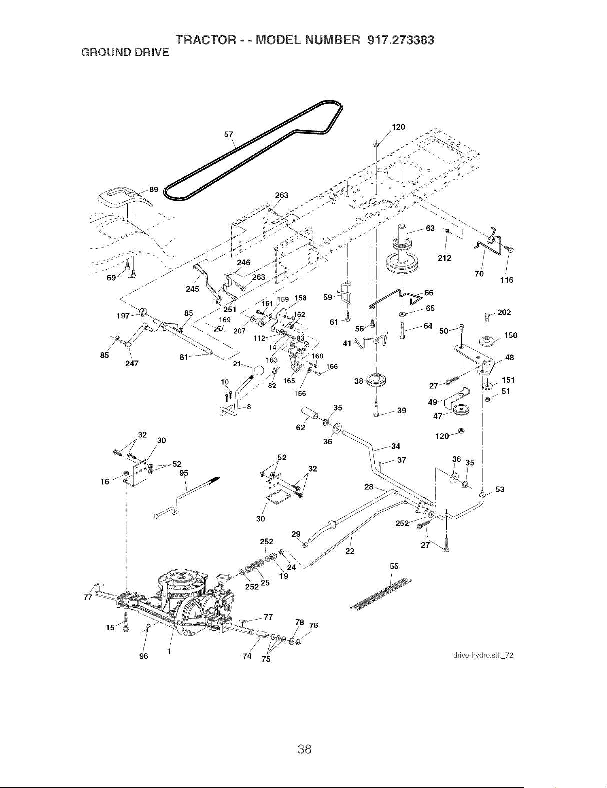
TRACTOR - ° MODEL NUMBER 917.273383
GROUND DRIVE
36 35
28 _ I 53
29 i
252 \ 27_
22
252 25
55
1o
1
96
78 76
74 75
drive.hydro,stlt 72
38

TRACTOR o o MODEL NUMBER 917.273383
GROUND DRmVE
KEY PART KEY PART
NO, NO, DESCRiPTiON NO, NO, DESCRiPTiON
1 Transaxle Peerless LTH2000 70 134683
(See Breakdown) 74 137057
8 165866 Rod Shift Fender Adjust 75 121749X
10 STD561210 Pin Cotter 1/8 x 1 CAD 76 STD581075
14 10040400 Washer Lock Hvy Helical 77 123583X
15 74490544 Bolt Hex FLGHD 5/16-18 Gr=5 78 121748X
16 STD541431 Nut Lock Hex W/Ins= 5/16-18 unc 81 178140
19 STD541437 Nut Lock Hex W/Wsh 3/8-16 Unc 82 165711
21 130564 Knob 1/2-13 83 19171216
22 178141 Rod, Brake 85 150360
24 73350600 Nut, HexJam 3/8-16 Unc 89 188309X428
25 106888X Spring, Brake Rod 95 178134
27 STD561210 Pin Cotter 1/8 x 3/4 CAD= 96 4497H
28 175765 Rod, Parking Brake 112 19091210
29 71673 Cap, Parking Brake 116 72140608
30 174973 Bracket, Transaxie 120 73900600
32 74760512 Bolt Hex Hd 5/16-18 Uric x 3/4 150 175456
34 175578 Shaft, Foot Pedal 151 19133210
35 120183X Bearing, Nylon 156 166002
36 19211616 Washer 158 165589
37 1572H Pin, Roll 159 183900
38 179114 Pulley, Composite 161 72140406
39 72110622 Bolt Rdhd 3/8-16 uric x 2 3/4 Gr= 162 73680400
5 163 74780416
41 175556 Keeper, Belt IdIer 165 165623
47 127783 PulIey, Idler, V-Groove 166 17490510
48 154407 BelIcrank, Clutch 168 165492
49 123205X Retainer, Belt 169 165580
50 72110612 Bolt Cart Sh 3/8-16 x 1-1/2 Gr 5 197 169613
51 STD541437 Nut Crownlock 3/8-16 Unc 198 169593
52 STD541431 Nut, Crownlock 5/16-18 Unc 202 72110614
53 105710X Link, Clutch 212 145212
55 105709X Spring, Return, Clutch 245 178122
56 17060620 Screw 3/8-16 x 1-1/4 246 178121
57 178138 V-Belt 247 181462
59 169691 Keeper, Center Span 251 17060516
61 17120614 Screw 3/8-16 x =875 252 19131616
62 8883R Cover, PedaI 263 17000612
63 175410 PulIey, Engine
64 173937 Bolt Hex 7/16-20 x 4 Gr=5
65 STD551143 Washer
66 154778 Keeper Belt Engine Hydro
69 142432 Screw Hex, Wsh, Hi-Lo 1/4 x 1/2
unc
Keeper Belt Engine
Spacer
Washer 25/32 x 1-1/4 x 16 Ga=
E-Ring
Key, Square
Washer 25/32 x 1-5/8 x 16 Ga=
Shaft Asm Cross Tapered
Spring Torsion
Washer 17/32 x 3/4 x 16 Ga=
Nut Lock Center 1/4-28 FNTHD
Console, Shift
Disconnect Asm Rod Bypas LTH
Retainer Spring 1" Zinc/Cad
Washer 9/32 x 3/4 x 10 Ga=
Bolt Rdhd Sqneck 3/8-16 x 1
Nut Lock Fig 3/8-16
Spacer Retainer
Washer 13/32 x 2 x 10 Ga=
Washer Srrted 5/16 ID x 1=125
Bracket Shift Mount
Hub Shift
Bolt Rdhd Sqnk 1/4-20 x 3/4 Gr 5
Nut Crownlock 1/4-20 Unc
Bolt Hex Fin 1/4-20 Uric x 1 Gr 5
Bracket Pivot Lever
Screw 5/16-18 x 5/8
Bolt Shoulder 5/16-18 x =561
PIate Fastening
Nyliner Snapqn 5/8'qD
Washer Nyl 7/8 ID x ,105" Hyd
Bolt Cart Sh 3/8-16 x 1-3/4 Gr=5
Nut Hex Flange Lock
Strap Torque Lh LTH2000
Strap Torque Rh LTH2000
Link Shift Transaxle LTH2000
Screw 5/16-18 x 1
Washer 13/32 x 1 x 16 Ga=
Screw Hex Wsh Thdr 3/8-16 x 3/4
NOTE: AII component dimensions given in U=S=inches
1 inch = 25=4 mm
39
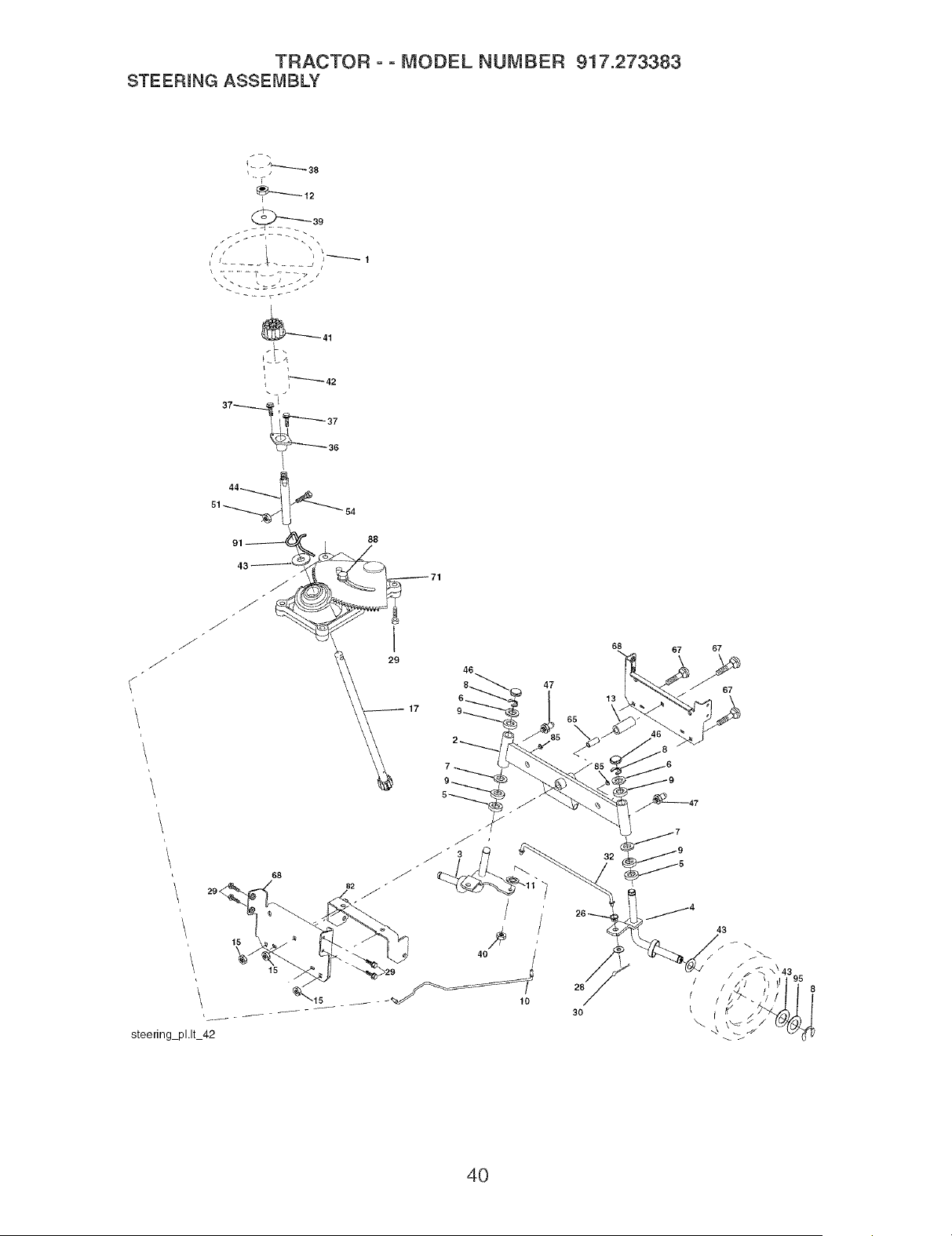
TRACTOR ° ° MODEL NUMBER 917.273383
STEERmNG ASSEMBLY
t- - ;_--_38
_39
J
37---_-!"
91 _ j_
88
I
29
46
8_
47
65
67 67
67
\
steering pl.lt 42
26
/
28
l
30 I
43
8
4O

TRACTOR o o MODEL NUMBER 917.273383
STEERmNG ASSEMBLY
KEY PART
NO. NO. DESCRmPTmON
1 186780
2 175131
3 169840
4 169839
5 6266H
6 121748X
7 19272016
8 12000029
9 3366R
10 175121
11 STD551137
12 73940800
13 136518
15 145212
17 180641
26 126847X
28 19131416
29 17000612
30 STD561210
32 130465
36 155099
37 152927
38 186781
39 19183812
40 73540600
41 186737
42 145054X428
43 121749X
44 180640
46 121232X
47 183226
51 73540400
54 71130420
65 160367
67 72140618
68 169827
71 175146
82 169835
85 133835
88 175118
91 175553
NOTE: All component
1 inch = 25.4 mm
Steering Wheel
Axle Assembly
Spindle Assembly, L.H.
Spindle Assembly, R.H.
Bearing, Race, Thrust, Hardened
Washer 25/32 x 1-5/8 x 16 Ga.
Washer 27/32 x 1-1/4 x 16 Ga.
Ring, Klip
Bearing, Steering Column
Draglink
Washer, Lock
Nut Hex Jam Toplock 1/2-20 unf
Spacer Bearing AxIe Front
Nut, Hex FIange Lock
Shaft Assembly, Steering
Bushing, Link, Drag
Washer 13/32 x 7/8 x 16 Ga.
Screw 3/8-16 x 3/4
Pin Cotter
Rod, Tie
Bushing, Steering
Screw
insert, Steering Wheel
Washer 9/16 x 2-3/8
Nut Crownlock 3/8-24 unf
Adaptor, Steering Wheel
Boot, Steering Shaft
Washer 25/32 x 1-1/4 x 16 Ga.
Extension Shaft Steering
Cap, Spindle
Fitting, Grease
Nut Crownlock 1/4-28
Bolt Hex 1/4-28 unfx 1-1/4 Gr. 8
Spacer Brace Axle
Bolt RDHD Sqnk 3/8-16 x 2-1/4
Axle, Brace
Steering Asm.
Bracket Susp. Chassis Front
Fastener Christmas Tree
Bolt Shoulder 7/16-20
CHipSteering
dimensions given in U.S. inches
41
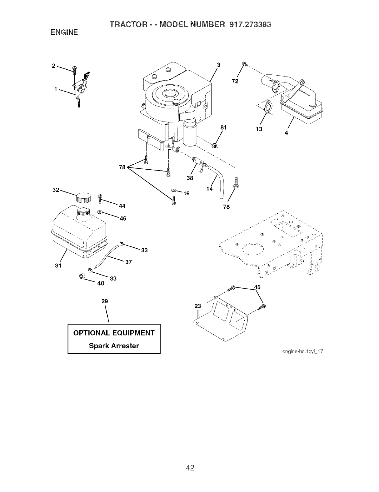
ENGINE
TRACTOR ° ° MODEL NUMBER 917.273383
78
31
33
37
29
\
OPTIONAL EQUIPMENT
Spark Arrester
38
81
14
23
13
4
I
/
78
engine-bs=lcyl 17
42

ENGINE
TRACTOR o o MODEL NUMBER 917.273383
KEY PART
NO, NO, DESCRIPTION
1 170545
2 17720408
3
4 137352
13 165291
14 148456
16 STD551237
23 169837
29 137180
31 184900
32 140527
33 123487X
37 137040
38 181654
40 124028X
44 17670412
45 17000612
46 19091416
72 183906
78 17060620
81 73510400
NOTE: Atlcomponent
linch = 25.4 mm
Control Throttle/Choke
Screw Hex Thd Cut 1/4-20 x 1/2
Engine Briggs Model 31C707-0230-E1
(See Breakdown)
Muffler Exhaust B&S Lt
Gasket 1 313 IdTin Plated
Tube Drain oil easy
Washer Lock Ext Tooth 3/8
Shield Browning/Debris Guard
Arrestor Spark
Tank Fuel 1 25 Fr
Cap Asm Fuel
Clamp Hose BIk
Line Fuel 20"
Plug drain oil easy
Bushing Snap Nyt BIk Fuel Line
Screw Hexwsh Thdrol 1/4-20 x 3/4
Screw 3/8-16 x 3/4
Washer 9/32 x 7/8 x 16 Ga.
Screw Socket Head 5/16-18 x 1
Screw 3/8-16 x 1-1/4
Nut Flange 1/4-20 Starter Nut
dimensions given in U.S. inches
43

TRACTOR ° ° MODEL NUMBER 917.273383
SEAT ASSEMBLY
17
seat It.knob 9
12
5
i
11
6
"/ 21
KEY PART
NO. NO.
1 188716
2 180166
3 71110616
4 19131610
5 145006
6 STD541437
7 124181X
8 17000616
9 19131614
10 180186
11 166369
DESCRIPTION
Seat 3350 BIWbIk Craftsman
Bracket Pnt Pivot Seat (blk)
Bolt Fin Hex 3/8-16 unc x 1
Washer 13/32 x 3/4 x 10 Ga.
Clip Push In Hinged
Nut Hex Lock w/Ins 3/8-16 unc
Spring Seat Cprsn 2 250 BIk Zi
Screw 3/8-16 x 1
Washer 13/32 x 1 x 14 Ga.
Pan Pnt Seat
Knob Seat Adj Wingnut
KEY PART
NO, NO,
12 121246X
13 121248X
14 72050412
15 134300
16 121250X
17 123976X
21 171852
22 STD541431
24 19171912
DESCRIPTION
Bracket Pnt Mounting Switch
Bushing Snap BIk Nyl 50 Id
Bolt Rdhd Sht Nk 1/4-20 x 1-1/2
Spacer Split 28 x 96 Zinc
Spring Cprsn 1 27 BIk Pnt
Nut Lock 1/4 Lge Hg Gr. 5 Zinc
Bolt Shoulder 5/16-18 unc*2A
Nut Hex Lock w/Ins 5/16-18
Washer 17/32 x 1-3/16 x 12 Ga.
NOTE: All component dimensions given in U.S. inches
1 inch = 25.4 mm
44
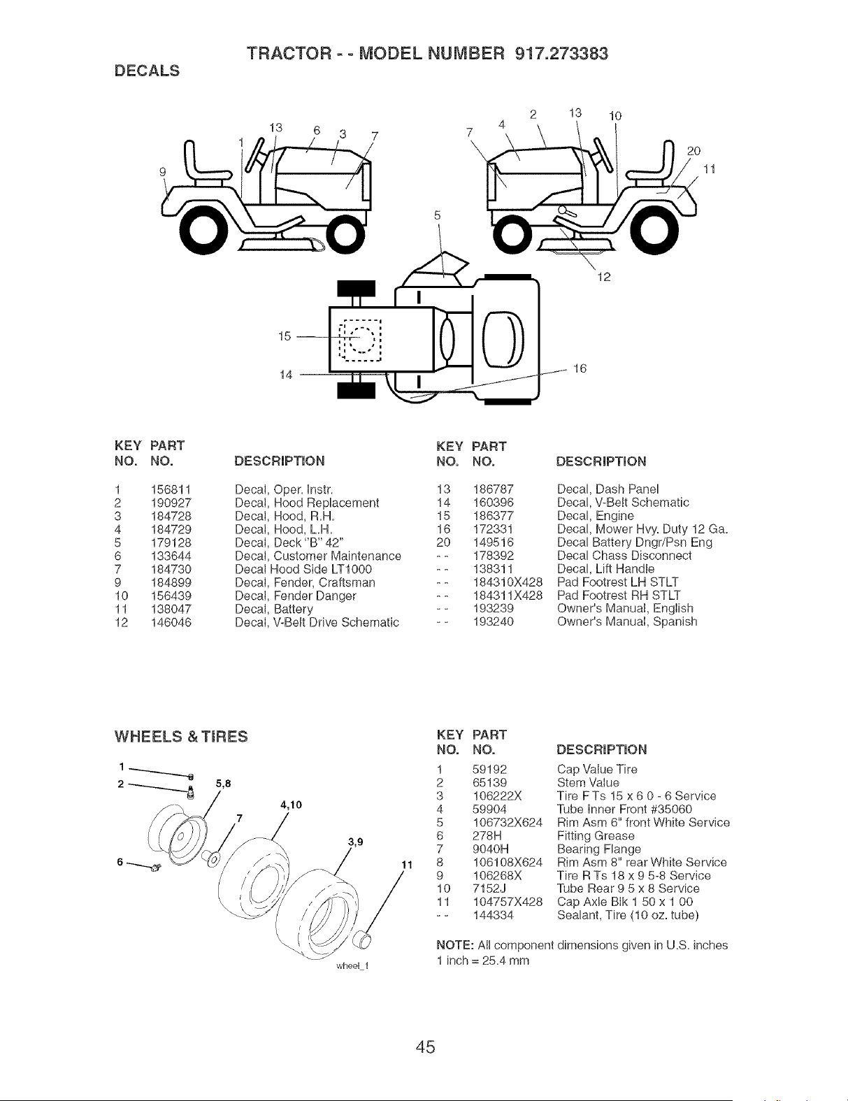
DECALS
TRACTOR o o MODEL NUMBER 917.273383
13 6 3 7
1
2 13 10
2O
11
15--
14
12
16
KEY PART
NO. NO.
1 156811
2 190927
3 184728
4 184729
5 179128
6 133644
7 184730
9 184899
10 156439
11 138047
12 146046
DESCRIPTION
DecaI, Oper= instr.
Decal, Hood Replacement
Decat, Hood, R=H=
Decat, Hood, L.H=
DecaI, Deck "B" 42"
DecaI, Customer Maintenance
Decat Hood Side LT1000
DecaI, Fender, Craftsman
Decal, Fender Danger
Decal, Battery
Decal, V-Belt Drive Schematic
KEY PART
NO. NO.
13
14
15
16
2O
186787
160396
186377
172331
149516
178392
138311
184310X428
184311X428
193239
193240
DESCRIPTION
Decal, Dash Panel
Decal, V-Belt Schematic
Decal, Engine
Decal, Mower Hvy=Duty 12 Ga=
Decal Battery DngdPsn Eng
Decal Chass Disconnect
Decal, Lift Handle
Pad Footrest LH STLT
Pad Footrest RH STLT
Owner's Manual, English
Owner's Manual, Spanish
WHEELS & TroPES
5,8
7
4,10
wheel 1
11
KEY PART
NO. NO.
1 59192
2 65139
3 106222X
4 59904
5 106732X624
6 278H
7 9040H
8 106108X624
9 106268X
10 7152J
11 104757X428
-- 144334
DESCRIPTION
Cap "ValueTire
Stem Value
Tire FTs 15 x 6 0 - 6 Service
Tube inner Front #35060
Rim Asm 6" front White Service
Fitting Grease
Bearing Flange
Rim Asm 8" rear White Service
Tire R Ts 18 x 9 5-8 Service
Tube Rear 9 5 x 8 Service
Cap Axle BIk 1 50 x 1 00
Sealant, Tire (10 oz. tube)
NOTE: All component dimensions given in U.S. inches
1 inch = 25.4 mm
45
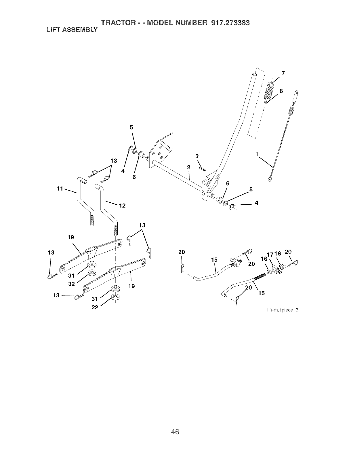
TRACTOR o o MODEL NUMBER 917.273383
LmFTASSEMBLY
7
11
19
13
13
12
13
3
\
6
5
2O
18 20
46

TRACTOR o o MODEL NUMBER 917.273383
LmFTASSEMBLY
KEY PART
NO. NO. DESCRIPTION
1 159460 Washer Asm HnnerSpring W/Plunger
2 159471 Shaft Asm. Lift
3 105767X Pin Groove
4 12000002 E Ring #5133-62
5 19211621 Washer 21/32 x 1 x21Ga.
6 120183X Bearing Nytong
7 125631X Grip HandIe Fluted
8 122365X Button Plunger Read
11 139865 Link Asm Lift LH.
12 139866 Link Asm Lift R.H.
13 STD624008 Retainer Spring
15 173288 Link Front
16 73350800 Nut Jam Hex 1/2-13 unc
17 175689 Trunnion
18 73800800 Nut Lock w/Wsh 1/2-13 unc
19 139868 Arm Suspension Mower
20 163552 Retainer Spring
31 169865 Bearing, Pvt. Lift
32 73540600 Nut Crownlock 3/8-24
NOTE: All component dimensions given in U.S. inches
1 inch = 25.4 mm
47
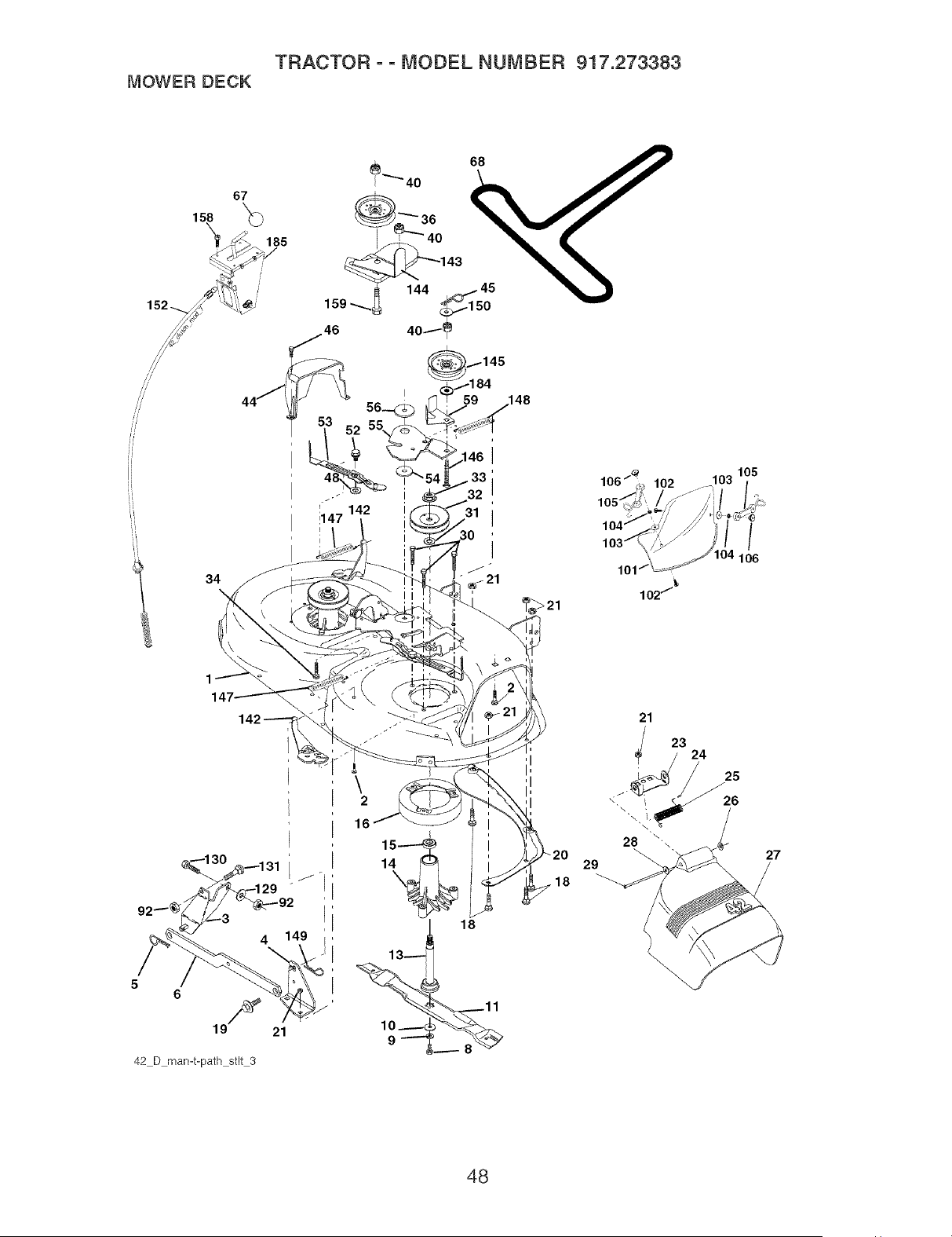
TRACTOR oo MODEL NUMBER 917.273383
MOWERDECK
158
34
\
142
5
6
19F 21
42 D man-t-path stlt 3
27
48
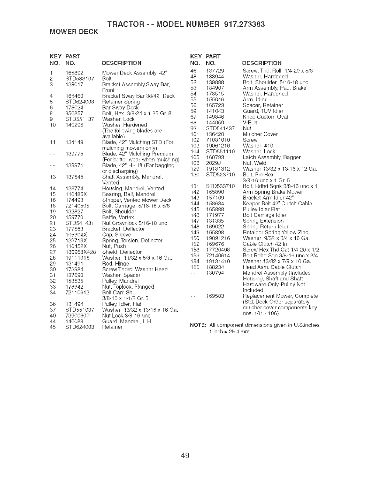
TRACTOR o o MODEL NUMBER 917.273383
MOWER DECK
KEY PART KEY PART
NO. NO. DESCRiPTiON NO. NO.
1 165892 Mower Deck AssembIy, 42" 46 137729
2 STD533107 Bolt 48 133944
3 138017 Bracket Assembly, Sway Bar, 52 139888
Front 53 184907
4 165460 Bracket Sway Bar 38/42" Deck 54 178515
5 STD624008 Retainer Spring 55 155046
6 178024 Bar Sway Deck 56 165723
8 850857 Bolt, Hex 3/8-24 x 1=25 Gr=8 59 141043
9 STD551137 Washer, Lock 67 149846
10 140296 Washer, Hardened 68 144959
92 STD541437
(The fol!owing blades are
avaiIable) 101 136420
11 134149 Blade, 42" MuIching STD (For 102 71081010
mulching mowers onIy) 103 19061216
- - 139775 Blade, 42" MuIching Premium 104 STD551110
(For better wear when mulcNng) 105 160793
- - 138971 Blade, 42" Hi-Lift (For bagging 106 2029J
or discharging) 129 19131312
13 137645 Shaft AssembIy, Mandrel, 130 STD523710
Vented
14 128774 Housing, Mandrel, Vented 131 STD533710
15 110485X Bearing, Bail, Mandrel 142 165890
16 174493 Stripper, Vented Mower Deck 143 157109
18 72140505 Bolt, Carriage 5/16-18 x 5/8 144 158634
19 132827 Bolt, Shoulder 145 165888
20 159770 Baffle, Vortex 146 171977
147 131335
21 STD541431 Nut Crownlock 5/16-18 unc
23 177563 Bracket, Deflector 148 169022
24 105304X Cap, Sleeve 149 165898
25 123713X Spring, Torsion, Deflector 150 19091216
26 110452X Nut, Push 152 169676
27 130968X428 Shield, Deflector 158 17720408
28 19111016 Washer 11/32 x 5/8 x 16 Ga= 159 72140614
29 131491 Rod, Hinge 184 19131410
30 173984 Screw Thdrol Washer Head 185 188234
31 187690 Washer, Spacer - - 130794
32 153535 Pulley, Mandrel
33 178342 Nut, Toplock, Flanged
34 72110612 Bolt Cam Sh=
3/8-16 x 1-1/2 Gr=5 - - 169583
36 131494 Pulley, idler, Flat
37 STD551037 Washer 13/32 x 13/16 x 16 Ga=
40 73900600 Nut Lock 3/8-16 unc
44 140088 Guard, Mandrel, LH=
45 STD624003 Retainer
DESCRIPTION
Screw, Thd= Roll 1/4-20 x 5/8
Washer, Hardened
Bolt, Shoulder 5/16-18 unc
Arm Assembly, Pad, Brake
Washer, Hardened
Arm, Hdler
Spacer, Retainer
Guard, TUV Idler
Knob Custom Ova!
V-Belt
Nut
Mulcher Cover
Screw
Washer #10
Washer, Lock
Latch Assembly, Bagger
Nut, Weld
Washer 13/32 x 13/16 x 12 Ga=
Bolt, Fin Hex
3/8-16 uncx 1 Gr=5
Bolt, Rdhd Sqnk 3/8-16 unc x 1
Arm Spring Brake Mower
Bracket Arm Idler 42"
Keeper Belt 42" Clutch Cable
Puiley Idler Flat
Bolt Carriage Idler
Spring Extension
Spring Return Idler
Retainer Spring Yellow Zinc
Washer 9/32 x 3/4 x 16 Ga=
Cable CIutch 42 In
Screw Hex Thd Cut 1/4-20 x 1/2
Bolt Rdhd Sqn 3/8-16 unc x 3/4
Washer 13/32 x 7/8 x 10 Ga=
Head Asm= Cable Clutch
Mandret Assembly dnciudes
Housing, Shaft and Shaft
Hardware Oniy-Pulley Not
Included
RepIacement Mower, Complete
(Std= Deck-Order separately
muicher cover components key
nos= 101 - 106)
NOTE: All component dimensions given in U.S.inches
1 inch = 25.4 mm
49

TRACTOR ° ° MODEL NUMBER 917.273383
PEERLESS TRANSAXLE - - MODEL NUMBER LTH2000
':::::::x:< 4
115 87
3
200
25
22
5O

TRACTOR o o MODEL NUMBER 917.273383
PEERLESS TRANSAXLE ° ° MODEL NUMBER LTH2000
KEY PART KEY PART
NO. NO. DESCRIPTION NO. NO. DESCRIPTION
1 772151 Cover LH. 70 786196 Spacer .625.765
3 770135 Case 79 792201 Spring
5 776355 Counter Shaft 85 792154 OH FilI Hug
6 778263 Spur Gear 11T 87 788088A Oil Seal 3/4"
9 786197 Neutral Sleeve (.572) 99 792141 Washer .377HD .058W
13 778368 Bevel Gear dncl. 14) (13 Teeth) 100 792200 Snubber Washer
14 778368 BeveI Gear dncl. 13) (13 Teeth) 101 792199 Snubber Spring .47HD
15 778373 Ring Gear (54 Teeth) 102 792184 Washer .437UD .078W
17 786139 Drive Pin 103 792193 Screw, 1/4-28 x .490
22 792194 Spring 104 792198 Nut, 3/8-24
23 792195 Washer .750 HD 105 780096 Washer .625 HD.057W
25 792073A Screw 1/4-20 x lq/4" 106 786162 SIeeve Assembly
26 792125 Retaining Ring 107 792046 Screw, 1/4-20 x 1"
28 792035 Retaining Ring 109 788104 "O" Ring
29 780065 Washer .627 HD.091W 113 786199 SIeeve Ass'y dnci. 157)
31 780189 Washer .563 HD.062W 114 786200 SIeeve Ass'y dncL 87)
36 790071 Brake Disk 115 786198 SIeeve Assembty (hci. 87)
37 790007 Brake Pad PIate 127 784384 Shift Lever Ass'y dnct. 109)
38 799021 Brake Pad 150 788093A Liquid Gasket RTV Silicon
40 792204 Roll Pin .25 157 788102 Oil Seal 9/16"1D
41 790102 Brake Lever 180 730229 BOil Spec. (80W90)
42 792202 Screw, 1/4-20 x 3/4 182 788103 Grommet
42A 792203 Screw, 1/4-20 x 1-3/4 183 792118 Relief Valve
43 792171 Screw, 10-24 x .500 184 792196 Hose Barb
44A 790100 Inside Brake (Mach) 185 798050 Tubing 1/2 x 5
44B 790099 Outside Brake (Casting) 190 792150 Washer
45 790101 Actuator Rod 191 792151 Nut 7/16-20
47 774869 AxIe 16.812 200 794787 Differential (Gear Reduction
48 774688 AxIe 11.625 Drive)
49 778378 Spur Gear 18T 203 798044 PuIIey& Hub Ass'y
56 778379 Spur Gear 81T 206 798055 Disconnect Lever
65 780195 Washer .7501D .062W 207 798053 Mounting Plate
67 776440 Brakeshaft 208 798040 Fan
209 798054 Control Lever
210 794788 Hydro ModuIe LH Fender Con-
trol
51
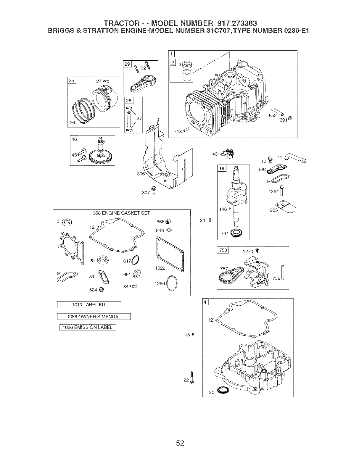
TRACTOR oo MODEL NUMBER 917.273383
BRmGGS& STRATTON ENGmNE=MODEL NUMBER 31C707,TYPE NUMBER 0230°E1
2_ 27
307_
3_
358 ENGINE GASKET SET
12
20@ 6170
61_ 691_
524 @ 8420
718 _
868 (_ 24
943 0
1266 0
434
741
lOI'114:_
584_
1264_
I 1019 LABEL KIT ]
I 1058 OWNER'S MANUAL ]
I 1036 EMISSION LABEL I
12
15_
22_
2O
52
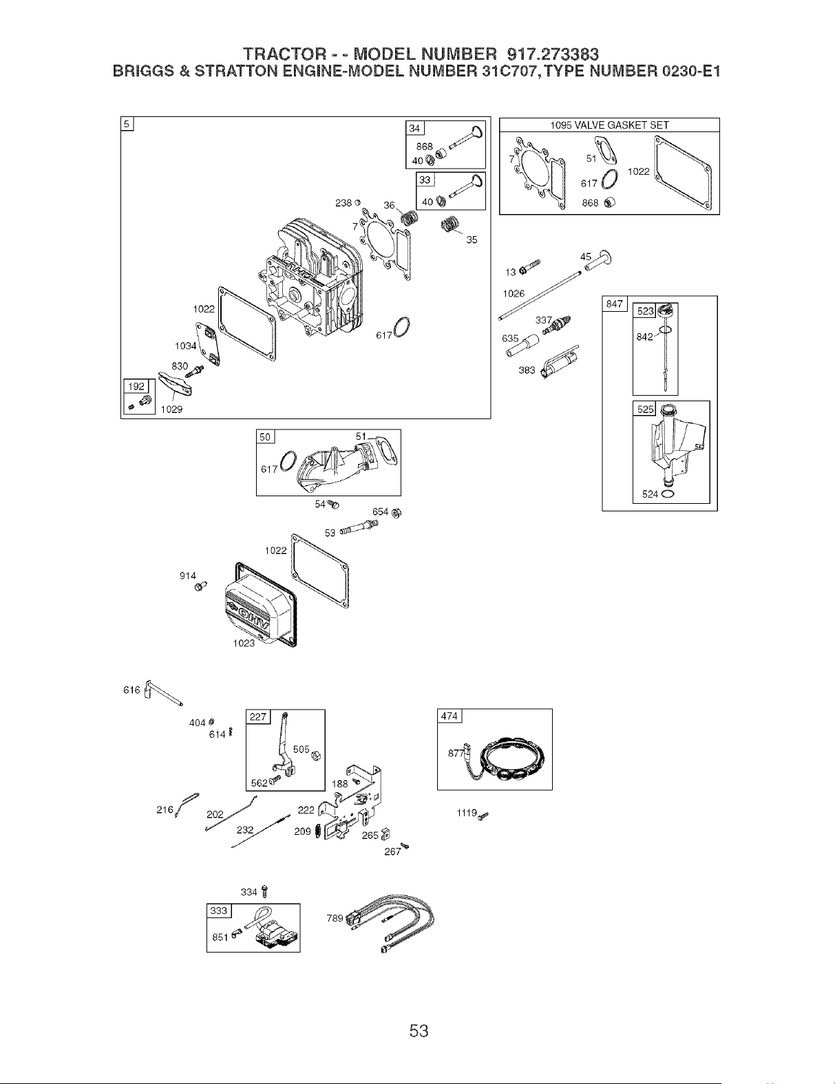
TRACTOR ° ° MODEL NUMBER 917.273383
BRmGGS & STRATTON ENGmNE=MODEL NUMBER 31C707,TYPE NUMBER 0230°E1
51
238 O
36
1022
6170
1022
914
1095 VALVE GASKET SET
7_ 51_2'_
617 0 1022
868
383
6240
1023
616
4o4,_ _ fr
614, /_
267 _'
334
53
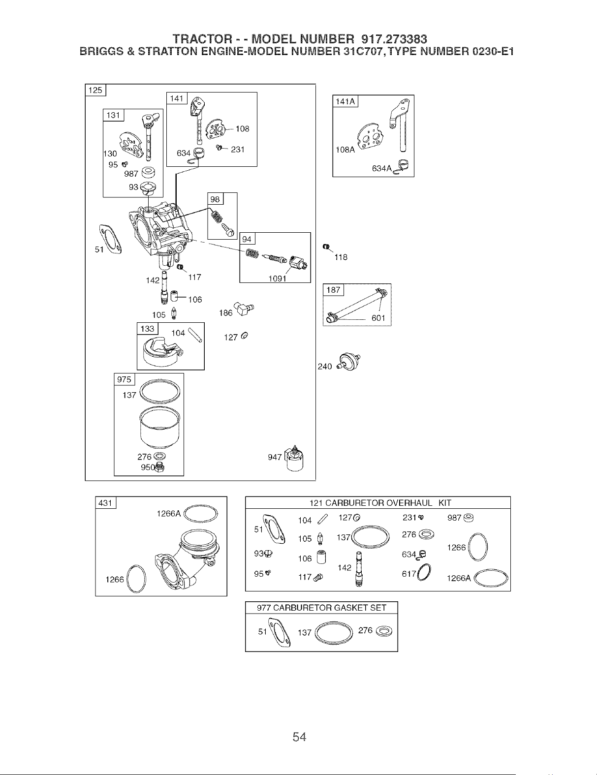
TRACTOR o o MODEL NUMBER 917.273383
BRmGGS & STRATTON ENGmNE=MODEL NUMBER 31C707,TYPE NUMBER 0230°E1
1091
947
108A
634A,_
e.
118
1266 0
1266A O
93'_
95 e'
601
121 CARBURETOR OVERHAUL KIT
104 _ 1270 231'_'
105 _ 137_=_
276@
634 e
1060 142 6170
117,_
987(_
1266 0
1266A O
977 CARBURETOR GASKET SET
1370 276@
54
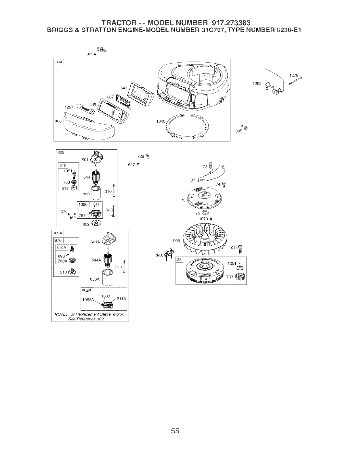
TRACTOR ooMODEL NUMBER 917.273383
BRmGGS& STRATTON ENGmNE=MODEL NUMBER 31C707, TYPE NUMBER 0230°E1
305A _
643
1267
30_
801
803_ 310 1
___1 _o_
579_46 _ 797 "_
802
1783A.@.
513
801A_
544A _ 31o_
803A
NOTE: For Replacement S_er Moto_
See Re.fence 309.
729
697 _
74
1070
lO0__ 1044_
1051&
55

TRACTOR o o MODEL NUMBER 917.273383
BRmGGS & STRATTON ENGmNE=MODEL NUMBER 31CT07,TYPE NU_,_BER 0230=E1
KEY PART KEY PART
NO. NO. DESCRmPTmON NO. NO. DESCRiPTiON
1 697174
2 399265
3 391086
4 697106
5 698147
7 692410
9 697109
10 697157
11 697113
12 697110
13 690360
15 690946
16 697127
20 690947
22 692125
23 693557
24 222698
25 697159
697160
697162
697163
26 697164
697165
697171
697172
27 697100
28 697099
29 697126
32 692852
33 495856
34 495857
35 691279
36 691279
37 697352
40 691752
43 691968
45 690564
46 697687
48 697761
o÷
o
50 690193
51 692137_G$+
53 690227
54 691148
73 697384
74 697987
75 690582
78 691003
93 690602 G
94 498030
95 691636
98 495800
104 690525 G
105 231855 G
106 690577 G
108 690464
108A 692344
117 694352 G
Cylinder Assembly 118 697492 Jet-Main (High Altitude)
Kit-Bushing/Seal (Magneto Side) 121 697241 Kit-Carburetor Overhaul
Seal-Oil (Magneto Side) 125 697190 Carburetor
Sump-Engine 127 695005 Plug-Welch
Head-Cylinder 130 691750 VaIve-Throttle
Gasket-Cylinder Head 131 494379 Kit-Throttle Shaft
Gasket-Breather 133 494381 FIoat-Carburetor
Screw (Breather Assembly) 137 281165 G$ Gasket-Float Bowl
Tube-Breather 141 495097 Kit-Choke Shaft (Manual Choke)
Gasket-Crankcase 141A 495931 Kit_Choke Shaft (Choke A Matic)
Screw (Cylinder Head) 142 697140 G Nozzle-Carburetor
Plug-Gil Drain 146 691639 Key-Timing
Crankshaft 186 692317 Connector-Hose
Seal-Oil (PTO Side) 187 691050 Line-Fuel (Cut to Required
Screw (Crankcase Cover/Sump) Length)
Flywheel 188 691693 Screw (Control Bracket)
Key-Flywheel 192 691986 Adjuster-Rocker Arm
Piston Assembly (Standard) 202 691841 Link-Mechanical Governor
Piston Assembly (.010" Over- 209 692208 Spring-Governor
size) 216 691840 Link-Choke
Piston Assembly (.020" Over- 222 694042 Bracket-Control
size) 227 691374 Lever-Governor Control
Piston Assembly (.030" Over- 231 691636 Screw (Choke Valve)
size) 232 691842 Spring-Governor
Ring Set (Standard) 238 691843 Cap-Valve
Ring Set (.010" Oversize) 240 394358 FiIter-Fuet
Ring Set (.020" Oversize) 265 691024 Clamp-Casing
Ring Set (=030" Oversize) 267 695134 Screw (Casing Clamp)
Lock-Piston Pin 276 692255 G$ Washer-Sealing
Pin-Piston 304 698402 Housing-Blower
Rod-Connecting (Standard) 305 697102 Screw (Blower Housing)
Screw (Connecting Rod) 305A 697103 Screw (Blower Housing)
VaIve-Exhaust 306 697107 Shield-Cylinder
Valveqntake 307 691003 Screw (Cylinder Shield)
Spring-Valve (Intake) 309 693551 Motor-Starter
Spring-Valve (Exhaust) 309A ........ Motor-Starter (For Replacement
Guard-HywheeI Starter Motor, See Reference
Retainer-Valve 309)
Slinger-Governor/Oil 310 690323 Bolt (Starter Motor)
Tappet-Valve 311 497608 Brush Set
Camshaft 311A 395538 Brush Set
Short Block (31C707-0230-E2 333 492341 Armature-Magneto
Replacement 334 691061 Screw (Magneto Armature)
Engine-art not available) 337 491055 PIug-Spark
Manifoldqntake 358 697191 Gasket Set-Engine
Gasketqntake 363 19203 Flywhee! PuIler
Stud (Carburetor)
Screw (Intake Manifold) RPM Settings: Low Speed: 1900-2100
Screen-Rotating High Speed: 3000-3200
Screw (Rotating Screen)
Washer (FlywheeI) ,, Included in Engine Gasket Set, Key=No= 358
Screw (Flywheel Guard) G Included in Carburetor Overhaul Kit, Key=No=
Bushing-Throttle Shaft 121
Kit-Hie Mixture $ Included in Carburetor Gasket Set, Key=No=
Screw (Throttle Valve) 977
Kit-Hie Speed + Included in \/aIve Gasket Set, Key=No=1095
Pin-Float Hinge
Valve-Float Needle NOTE: All component dimensions given in U=S=
Seatqnlet inches 1 inch = 25=4 mm
\iatve-Choke (Manual Choke)
VaIve-Choke (Choke A Matic)
Jet-Main (Standard)
56
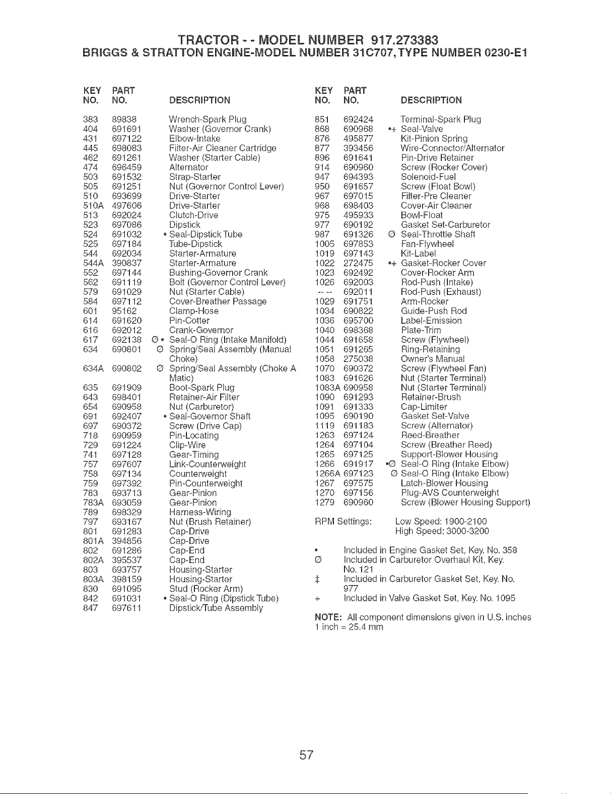
TRACTOR o o MODEL NUMBER 917.273383
BRJGGS & STRATTON ENGiNE=MODEL NUMBER 31C707,TYPE NUMBER 0230°E1
KEY PART KEY PART
NO. NO. DESCRiPTiON NO. NO. DESCRiPTiON
383 89838 Wrench-Spark Plug 851 692424 Terminal-Spark Plug
404 691691 Washer (Governor Crank) 868 690968 ,,+ Seal-Valve
431 697122 Elbow-Intake 876 495877 Kit-Pinion Spring
445 698083 Filter-Air Cleaner Cartridge 877 393456 Wire-Connector/Alternator
462 691261 Washer (Starter Cable) 896 691641 Pin-Drive Retainer
474 696459 Alternator 914 690960 Screw (Rocker Cover)
503 691532 Strap-Starter 947 694393 Solenoid-Fuel
505 691251 Nut (Governor Control Lever) 950 691657 Screw (Float Bowl)
510 693699 Drive-Starter 967 697015 Filter-Pre Cleaner
510A 497606 Drive-Starter 968 698403 Cover-Air Cleaner
513 692024 Clutch-Drive 975 495933 Bowl-Float
523 697086 Dipstick 977 690192 Gasket Set-Carburetor
524 691032 _,SeaFDipstick Tube 987 691326 @ SeaFThrottle Shaft
525 697184 Tube-Dipstick 1005 697853 Fan-Flywheel
544 692034 Starter-Armature 1019 697143 Kit-Label
544A 390837 Starter-Armature 1022 272475 ,,+ Gasket-Rocker Cover
552 697144 Bushing-Governor Crank 1023 692492 Cover-Rocker Arm
562 691119 Bolt (Governor Control Lever) 1026 692003 Rod-Push dntake)
579 691029 Nut (Starter Cable) .... 692011 Rod-Push (Exhaust)
584 697112 Cover-Breather Passage 1029 691751 Arm-Rocker
601 95162 Clamp-Rose 1034 690822 Guide-Push Rod
614 691620 Pin-Cotter 1036 695700 Label-Emission
616 692012 Crank-Governor 1040 698368 Plate-Trim
617 692138 G ,, SeaFO Ring (Intake Manifold) 1044 691658 Screw (Flywheel)
634 690801 @ Spring/Seal Assembly (Manual 1051 691265 Ring-Retaining
Choke) 1058 275038 Owner's Manual
634A 690802 @ Spring/Seal Assembly (Choke A 1070 690372 Screw (Flywheel Fan)
Matic) 1083 691626 Nut (Starter Terminal)
635 691909 Boot-Spark Plug 1083A 690958 Nut (Starter Terminal)
643 698401 Retainer-Air Filter 1090 691293 Retainer-Brush
654 690958 Nut (Carburetor) 1091 691333 Cap-Limiter
691 692407 _,Seal-Governor Shaft 1095 690190 Gasket Set-Valve
697 690372 Screw (Drive Cap) 1119 691183 Screw (Alternator)
718 690959 Pin-Locating 1263 697124 Reed-Breather
729 691224 Clip-Wire 1264 697104 Screw (Breather Reed)
741 697128 Gear-Timing 1265 697125 Support-Blower Rousing
757 697607 Link-Counterweight 1266 691917 ,O Seal-O Ring (Intake Elbow)
758 697134 Counterweight 1266A 697123 G Seal-O Ring (Intake Elbow)
759 697392 Pin-Counterweight 1267 697575 Latch-Blower Housing
783 693713 Gear-Pinion 1270 697156 Plug-AVS Counterweight
783A 693059 Gear-Pinion 1279 690960 Screw (Blower Housing Support)
789 698329 Harness-Wiring
797 693167 Nut (Brush Retainer) RPM Settings: Low Speed: 1900-2100
801 691283 Cap-Drive High Speed: 3000-3200
801A 394856 Cap-Drive
802 691286 Cap-End ,, Included in Engine Gasket Set, Key. No. 358
802A 395537 Cap-End @ Included in Carburetor Overhaui Kit, Key.
803 693757 Housing-Starter No. 121
803A 398159 Housing-Starter _ Included in Carburetor Gasket Set, Key. No.
830 691095 Stud (Rocker Arm) 977
842 691031 ,, Seal-O Ring (Dipstick Tube) + Included in Valve Gasket Set, Key. No. 1095
847 697611 Dipstick/Tube Assembly
NOTE: AI! component dimensions given in U.S. inches
1 inch = 25.4 mm
57

58

SUGGESTED GUIDE FOR SIGHTING SLOPES FOR SAFE OPERATION
ONLY RIDE UP AND DOWN HILL,
NOT ACROSS HILL
15 DEGREES MAX.
&
1. Fold this page along dotted line indicated above.
2. Homd page before you so that its meltedge is vertically paraffem to a tree
trunk or other upright structure.
3. Sight across the fomd in the direction of hill smope you want to measure.
4. Compare the angme of the fomd with the smope of the hill

Your Home
For repair - in your home - of all major brand appliances,
lawn and garden equipment, or heating and cooling systems,
no matter who made it, no matter who sold it!
For the replacement parts, accessories and
owner's manuals that you need to do-it-yourself.
For Sears professional installation of home appliances
and items like garage door openers and water heaters.
1-800-4-MY-HOME ® Anytime, day or night
(1-800-469-4663) (U.S.A. and Canada)
www.sears.com www.sears.ca
Our Home
For repair of carry-in products like vacuums, lawn equipment,
and electronics, call or go on-line for the nearest
Sears Parts and Repair Center.
1-800-488-1222 Anytime, day or night (U.S.A. only)
www.sears.com
To purchase a protection agreement (U.S.A.)
or maintenance agreement (Canada) on a product serviced by Sears:
1-800-827-6655 (U.S.A.) 1-800-361-6665 (Canada)
iiiiiiiiiiiiiiiii
iiiiiiiiiiiiiiiii
iiiiiiiiiiiiiiiii
iiiiiiiiiiiiiiiii
iiiiiiiiiiiiiiiii
iiiiiiiiiiiiiiiii
iiiiiiiiiiiiiiiii
iiiiiiiiiiiiiiiii
iiiiiiiiiiiiiiiii
iiiiiiiiiiiiiiiii
iiiiiiiiiiiiiiiii
iiiiiiiiiiiiiiiii
iiiiiiiiiiiiiiiii
iiiiiiiiiiiiiiiii
iiiiiiiiiiiiiiiii
iiiiiiiiiiiiiiiii
iiiiiiiiiiiiiiiii
iiiiiiiiiiiiiiiii
iiiiiiiiiiiiiiiii
iiiiiiiiiiiiiiiii
iiiiiiiiiiiiiiiii
iiiiiiiiiiiiiiiii
iiiiiiiiiiiiiiiii
iiiiiiiiiiiiiiiii
iiiiiiiiiiiiiiiii
HHHHHHHH_
Para pedir servicio de reparaci6n
a domicilio, y para ordenar piezas:
1-888-SU-HOGAR sM
(1-888-784-6427)
Au Canada pour service en frangais:
1-800-LE-FOYERMC
(1-800-533-6937)
www.sears.ca
© Sears, Roebuckand Co.
02410
TM SM
® Registered Trademark / Trademark / Service Mark of Sears, Roebuck and Co.
TM
® Marca Registrada / Marca de Fabrica / SMMarca de Servicio de Sears, Roebuck and Co.
MCMarque de commerce / MDMarque depos_e de Sears, Roebuck and Co.
193239 7.12.04 MH Printed in U.S.A.