Loading ...
Loading ...
Loading ...
Setup
coil should be between 350 – 450 CFM per ton of cooling
outdoor unit. If the electric furnace is to be used with
smaller tonnage outdoor equipment, the variable speed
changing the motor control board (refer to Table 2. Variable
Speed Motor Application).
The cooling blower speed must be set to provide a
outdoor cooling capacity.
IMPORTANT
Variable Speed Motor
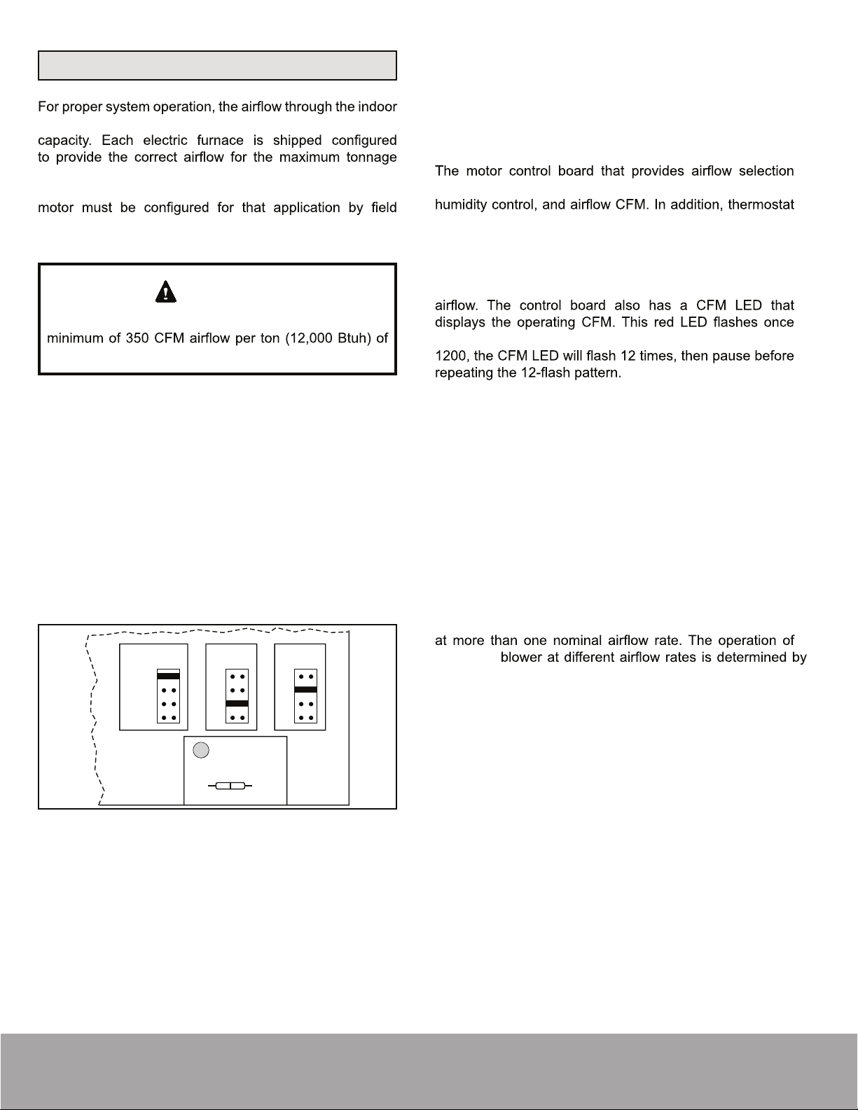
Locate the motor control board in the blower control box.
Set the HEAT and COOL CFM taps by moving the board
jumpers to the A, B, C, or D positions (see Figure 2) based
on the information found in Table 2. Variable Speed Motor
Application. The ADJUST tap on the control board can be
used to raise or lower the table CFMs. The (+) tap will raise
the table CFM by 10%, and the (–) tap will lower the table
CFM by 12%.
IMPORTANT:
When changing the control taps, the
high voltage must be off in order for the new settings to
take effect.
DEHUMIDIFY
CUT TO ENABLE
COOL
HEATADJUST
NORM A
B
C
D
A
B
C
D
(+)
(–)
TEST
D1
Figure 2. Motor Board Taps and Dehumidify Resistor
This model is designed for use with heat pumps as
well as air conditioning systems. The motor control
board needs to sense a signal on the “O” thermostat
wire in order to use cooling delay timing. For a straight
air conditioning system, connect the “O” wire to the 24
volt “R” wire.
also features LED indicators that display operating mode,
signals for emergency heat (EM), aux. heat (W1), reversing
valve (O), compressor stage 1 (Y1), compressor stage 2
(Y2), and blower (G) are all indicated by lit LED’s on this
board. If a humidistat is used, the dehumidify LED will light
when the humidistat opens and the motor runs at reduced
for each 100 CFM. For example: if the operating CFM is
Special note for units equipped with a humidistat: If
using a humidistat, the dehumidify resistor located on the
bottom right of the control board must be removed (see
Figure 2).
The HUM terminal on the board must be connected to
the Normally Closed contact of the humidistat so that the
board senses an open circuit on high humidity.
Application Table
The versatility of the variable speed motor enables the
performance of the modular blower to be tailored to the
different modes of operation encountered in heating and
cooling. All modular blowers are capable of operation
a modular
the control board taps and the thermostat (see Table 2.
Variable Speed Motor Application). Before beginning the
setup, become familiar with the information found in this
table.
The data in the application table is categorized by unit size
and mode of operation. Use the information provided to
determine the CFM taps needed for cooling and heating.
Page 6
mrcool.com
Loading ...
Loading ...
Loading ...