
Installation Manual
INDOOR COOKING
Smart Induction Cooktop
KICS
©2019 Hestan Commercial Corporation
EN
SAFETY DEFINITIONS
THIS INDICATES THAT DEATH OR SERIOUS INJURY MAY OCCUR
AS A RESULT OF NOT OBSERVING THIS WARNING
THIS INDICATES THAT MINOR OR MODERATE INJURY MAY
OCCUR AS A RESULT OF NOT OBSERVING THIS WARNING.
THIS INDICATES THAT DAMAGE TO THE APPLIANCE OR
PROPERTY MAY OCCUR AS A RESULT OF NOT OBSERVING THIS
WARNING.
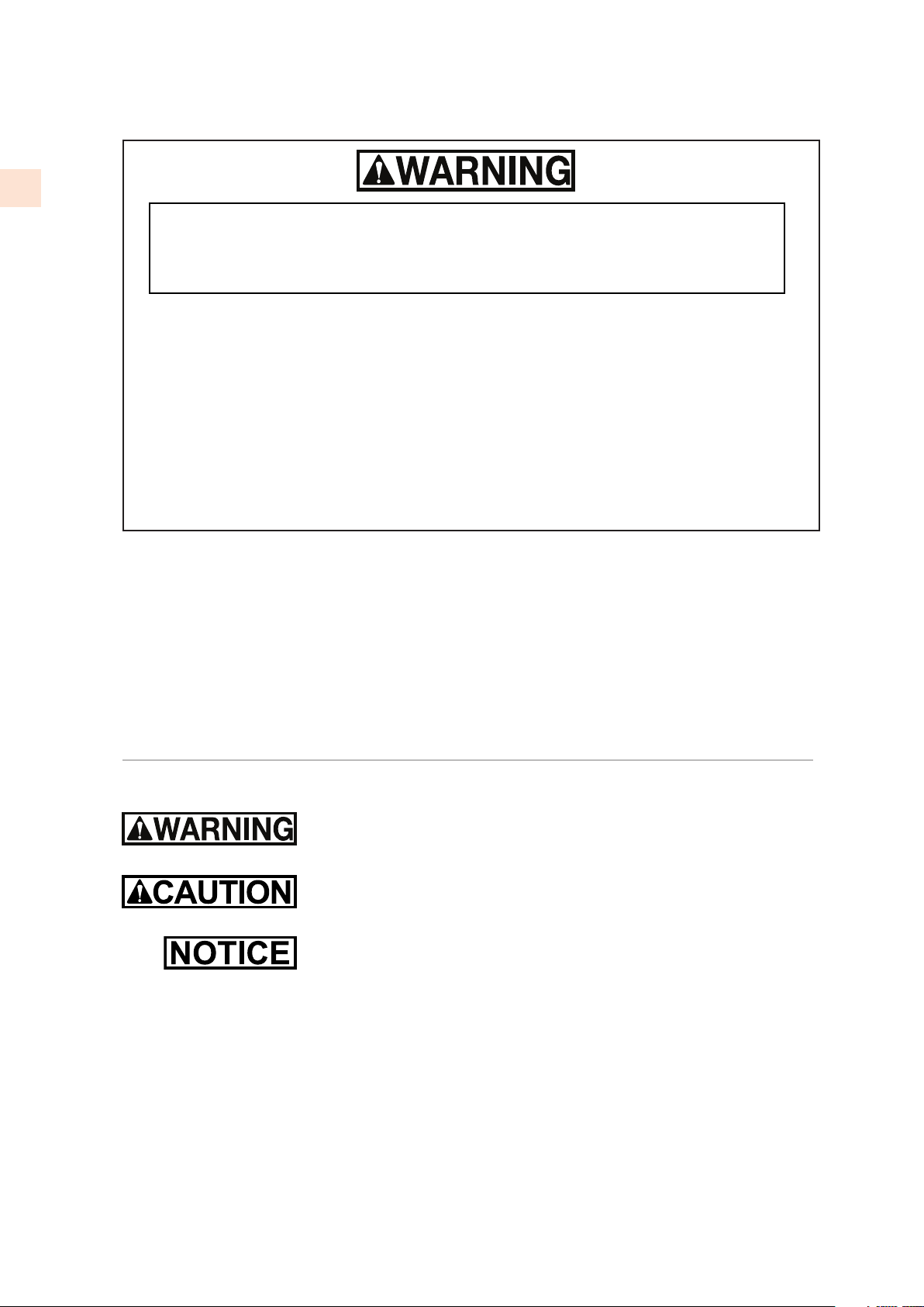
READ THESE INSTRUCTIONS CAREFULLY AND COMPLETELY BEFORE INSTALLING OR
USING YOUR APPLIANCE TO REDUCE THE RISK OF FIRE, BURN HAZARD, OR OTHER
INJURY. KEEP THIS MANUAL FOR FUTURE REFERENCE.
Do not store or use gasoline or other flammable vapors and liquids in the vicinity of this
or any other appliance.
Installation and service must be performed by a qualified installer or service agency.
DO NOT REPAIR, REPLACE OR REMOVE ANY PART OF THE APPLIANCE UNLESS
SPECIFICALLY RECOMMENDED IN THE MANUAL. IMPROPER INSTALLATION,
SERVICE OR MAINTENANCE CAN CAUSE INJURY OR PROPERTY DAMAGE. REFER
TO THIS MANUAL FOR GUIDANCE. ALL OTHER SERVICING SHOULD BE DONE BY
A QUALIFIED TECHNICIAN.
INSTALLER: LEAVE THIS MANUAL WITH THE OWNER OF THE APPLIANCE.
HOMEOWNER: RETAIN THIS MANUAL FOR FUTURE REFERENCE.
IF THE INFORMATION IN THIS MANUAL IS NOT FOLLOWED
EXACTLY, A FIRE OR EXPLOSION MAY RESULT CAUSING
PROPERTY DAMAGE, PERSONAL INJURY, OR DEATH.
©2019 Hestan Commercial Corporation
1
EN
When properly cared for, your Hestan appliance will provide safe, reliable service for many years.
When using this appliance, basic safety practices must be followed as outlined below.
IMPORTANT: Save these instructions for the local electrical inspector’s use.
INSTALLER: Please leave these Installation Instructions with the owner.
OWNER: Please retain these Installation Instructions for future reference.
Do NOT install this appliance outdoors.
SAFETY PRECAUTIONS - BEFORE YOU BEGIN
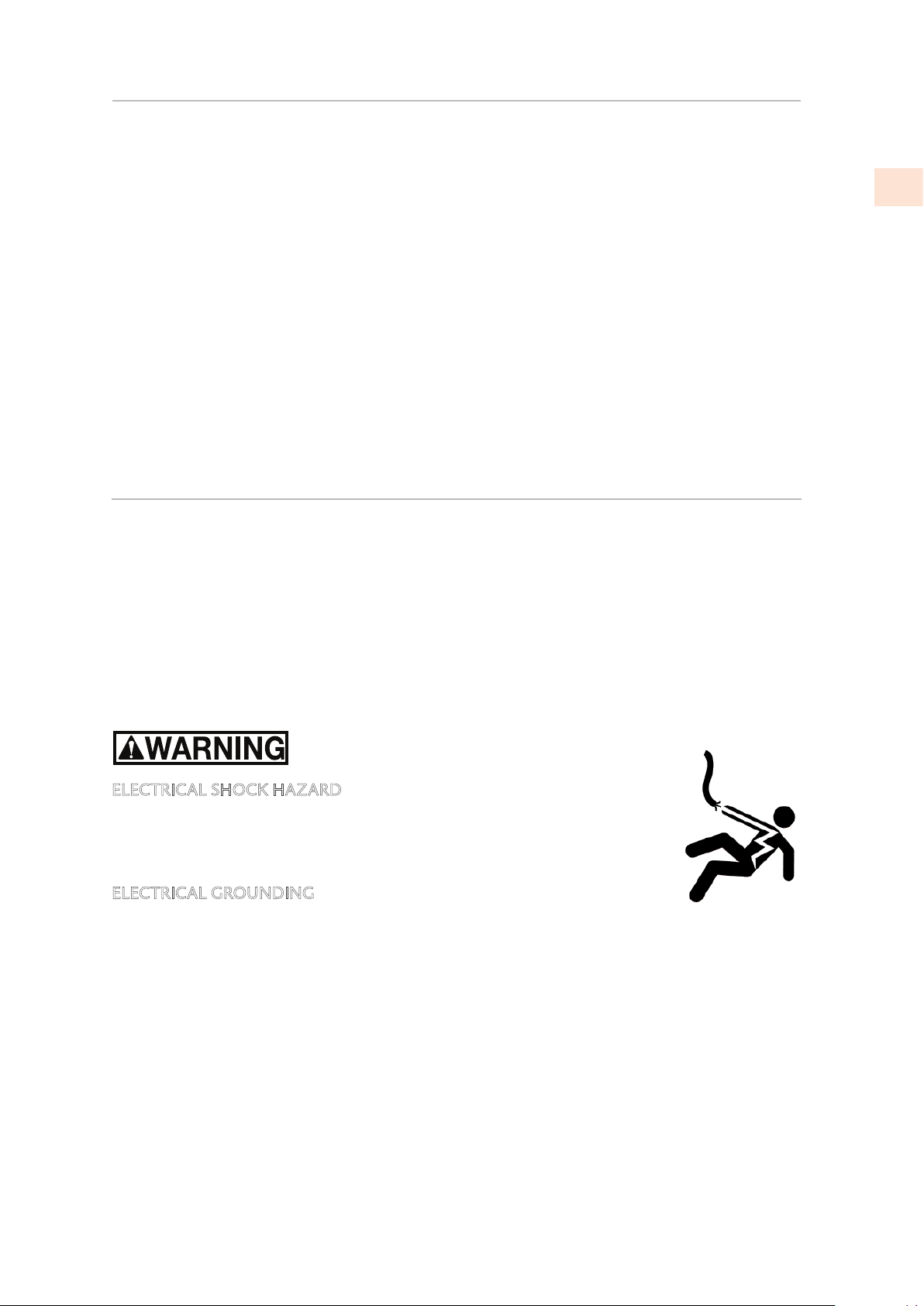
ELECTRICAL SHOCK HAZARD
Disconnect power before installing or servicing appliance. Failure to do so
can result in death or electrical shock.
ELECTRICAL GROUNDING
This appliance must be grounded. Grounding reduces the risk of electric
shock in the event of a short circuit. Read the ELECTRICAL CONNECTIONS section of this
manual for complete instructions.
DO NOT ground to a gas pipe.
DO NOT use an extension cord with this appliance.
DO NOT have a fuse in the NEUTRAL or GROUNDING circuit. A fuse in the NEUTRAL or
GROUNDING circuit could result in an electrical shock.
TABLE OF CONTENTS
1 SAFETY PRECAUTIONS - BEFORE YOU BEGIN
2 MODEL NUMBERS
2 RATING LABEL
2 REGULATORY / CODE REQUIREMENTS
3 CUTOUT DIMENSIONS AND REQUIREMENTS
6 COOKTOP INSTALLATION
9 ELECTRICAL CONNECTIONS
11 FINAL SETUP
12 PARTS LIST
12 SERVICE
©2019 Hestan Commercial Corporation
2
EN
MODEL NUMBERS
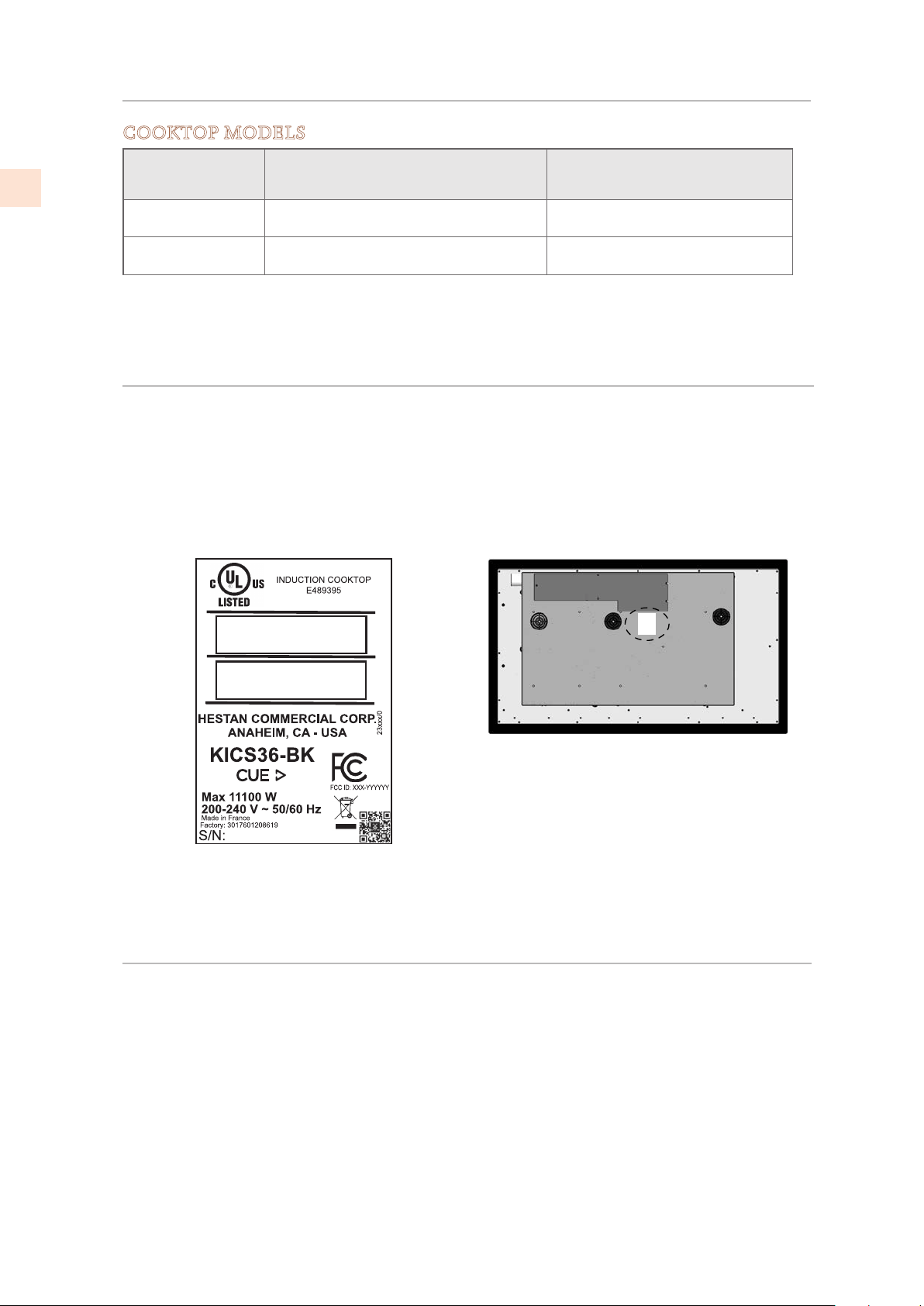
RATING LABEL
The rating label contains important information about your Hestan appliance such as the model
and serial number, electrical rating and the minimum installation clearances.
The rating label is located on the bottom of the cooktop.
If service is necessary, contact Hestan Customer Service with the model and serial number
information shown on the label.
COOKTOP MODELS
MODEL NO. DESCRIPTION
CIRCUIT BREAKER
REQUIRED
KICS30 30” Smart Induction Cooktop 40 Amp
KICS36 36” Smart Induction Cooktop 50 Amp
REGULATORY / CODE REQUIREMENTS
Installation of this cooking appliance must be made in accordance with local codes. In the
absence of local codes, this unit should be installed in accordance with the National Electrical
Code and local codes.
This appliance must be electrically grounded in accordance with local codes or in the absence of
local codes with the National Electrical Code
ANSI/NFPA 70
, or Canadian Electrical code
CSA
C22.1
.
Rating label
Figure 1. Typical rating label
©2019 Hestan Commercial Corporation
3
EN
CUTOUT DIMENSIONS AND REQUIREMENTS
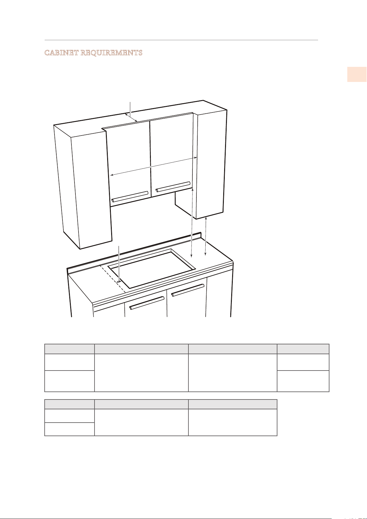
CABINET REQUIREMENTS
To eliminate the risk of burns or fire by reaching over heated surface units, cabinet storage units
located above the surface units should be avoided. If cabinet storage is to be provided, the risk can
be reduced by installing a range hood that projects horizontally a minimum of 5 inches [12.7 cm]
beyond the bottom of the cabinets.
Model A B C
KICS30
30” [76.2 cm] min. clearance
from countertop to
unprotected overhead surface,
or as required by ventilation
hood. *
18” [45.7 cm] min. height
from countertop to nearest
cabinet on either side of unit.
30” [76.2 cm]
min.
KICS36
36” [91.4 cm]
min.
Model
D E
KICS30
2” [5.1 cm] min clearance from
cutout to side wall on the left
or right of the unit. **
13” [33 cm] depth of
unprotected overhead
cabinets.
KICS36
* 30” [76.2 cm] minimum clearance between the top of the cooking surface and the bottom of an
unprotected wood or metal cabinet.
** It is permissible to mount the cooktop as close as 2” [5.1 cm] away from a cabinet or wall on one
side. The other side must be unobstructed.
B
A
C
D
E
WALL COVERING, CABINETS,
AND COUNTERTOP MUST
WITHSTAND HEAT UP TO
200°F [93ºC]
Figure 2. Cabinet clearances
©2019 Hestan Commercial Corporation
4
EN
CUTOUT DIMENSIONS AND REQUIREMENTS
(CONT.)
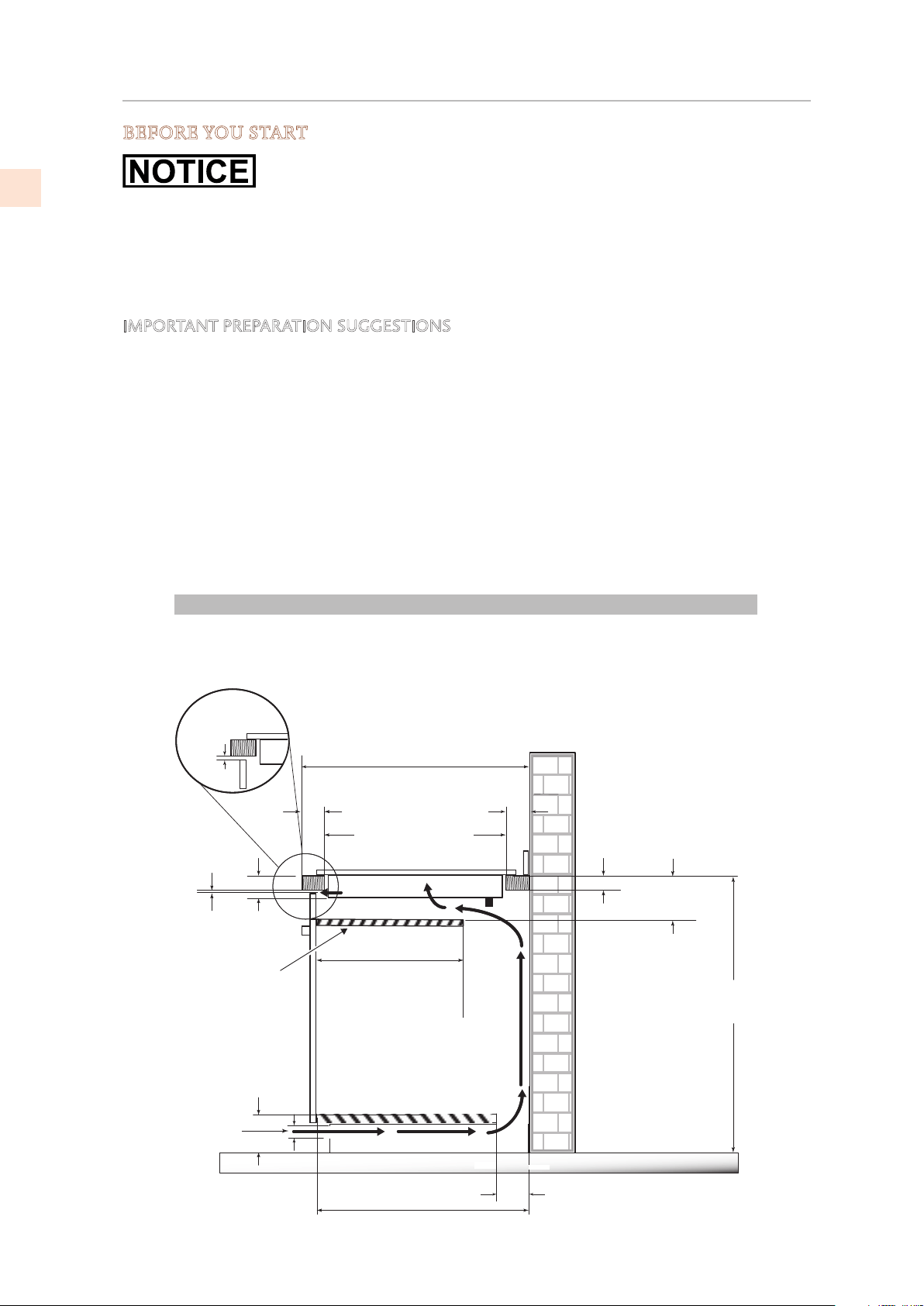
BEFORE YOU START
Do not install the cooktop above an unventilated oven or a dishwasher.
The cooktop is 2-1/2” [6.4 cm] deep, and requires a minimum 1” [2.5 cm] clearance below it.
If a drawer is directly below the cooktop, it and its contents must be heat resistant. Such a
drawer should be placed/arranged so that nothing can be drawn from the drawer into the
ventilation fans of the cooktop.
IMPORTANT PREPARATION SUGGESTIONS
Chamfer all exposed edges of decorative laminate to prevent damage from chipping.
Radius corners of cutout and file to ensure smooth edges and prevent corner cracking. A 1/4” or
3/8” [6.3 - 9.5 mm] diameter drilled hole at each corner to start the cut is recommended.
Rough edges, inside corners which have not been rounded and forced fits can contribute to
cracking of the countertop laminate.
If the countertop material is susceptible to moisture, the cut edges should be sealed with a
suitable sealer. All materials and adhesives must be able to withstand temperatures up to 200°F
[93°C].
The junction box must be accessible with the cooktop in place.
For service purposes it is advisable to have enough access to the bottom of the cooktop so that it
can be lifted out.
min
VERTICAL CLEARANCES
* The ventilation opening is to extend the full length of the cooktop cutout.
25” [635 mm]
min
”
2-1/2”
[64mm]
3
”
[76 mm]
2-1/2”
[65 mm]
1-5/8”
[40 mm]
max
1/4”
[6 mm]
min
36”
[915 mm]
24” [610 mm]
15-3/4”
[400 mm]
5”
[127 mm]
min
*1/4”
[6 mm]
min
min
19-7/16 [494 mm]
1-1/2
4-3/4
[120 mm]
[38 mm]
min
”
”
4”
[101 mm]
min
Partition
©2019 Hestan Commercial Corporation
5
EN
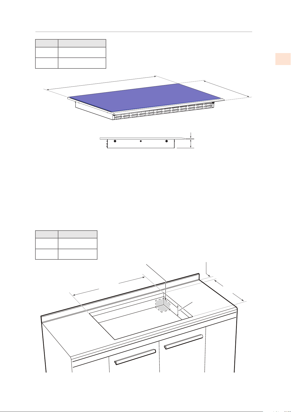
CUTOUT DIMENSIONS AND REQUIREMENTS
(CONT.)
Model W
KICS30 30-5/16” [77.0 cm]
KICS36 36-5/32” [91.8 cm]
Model F
KICS30 28-3/8” [72 cm]
KICS36 34-1/4” [87 cm]
Figure 3. Cooktop dimensions
21
- ¾”
[55.2 cm]
2-½”
[6.4 cm]
3/8
”
[9.5 mm]
W
2” [5.1 cm]
3-½” [8.9 cm]
min. depth
HOLE FOR
POWER CABLE
ENCLOSURE
BOTTOM
(OPTIONAL)
F
19-¼” [48,9 cm]
MIN. CLEARANCE
Figure 4. Cutout dimensions
©2019 Hestan Commercial Corporation
6
EN
COOKTOP INSTALLATION
EXCESSIVE WEIGHT HAZARD
Use two or more people to move and install cooktop. Failure to do so can result in back or other
injury.
CUT HAZARD
Beware of sharp edges. Wear protective gloves or use the polystyrene ends when carrying the
product. Failure to use caution could result in minor injury or cuts.
Always consult the countertop manufacturer for specific instructions.
Ensure the countertop is square and level and ensure no structural members interfere with space
requirements.
Prepare the cutout according to the instructions (see cutout dimensions).
Make sure the wall coverings, countertop and cabinets around the cooktop can withstand heat (up
to 200°F / 93°C).
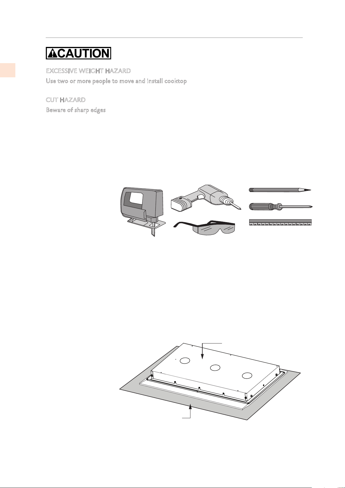
STEP 1
Remove packaging materials and literature package from the cooktop before beginning installation.
Read this Installation Manual carefully before you begin.
STEP 2
Place a towel or cloth
on the work surface.
Place the cooktop face
down on the protected
area.
Figure 5. Needed tools
COOKTOP HOUSING
TOWEL OR CLOTH
Figure 6. Protecting the surface
©2019 Hestan Commercial Corporation
7
EN
COOKTOP INSTALLATION
(CONT.)
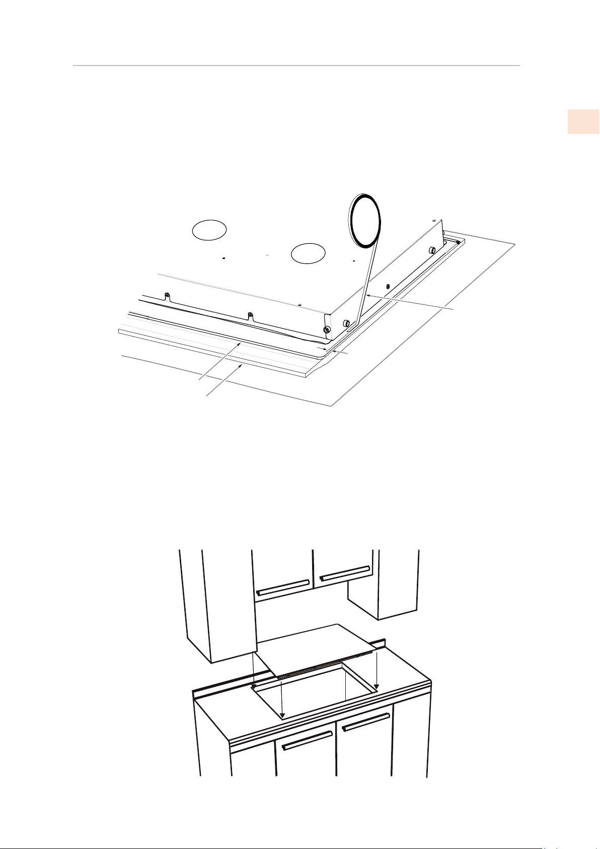
STEP 3
A foam tape is provided to seal the cooktop to the countertop. Apply tape to the underside of the
cooktop glass between the body of the cooktop and the inner edge of the metal frame.
There should be about 3/32” [2 mm] between the edge of the tape and the edge of the glass. Use
tape around the entire glass perimeter.
The tape will retain the cooktop and seal against leaks into the cabinet. Trim the tape ends so that
they meet with no gaps.
STEP 4
Make a final check that all required clearances are met.
Feed the cable through the cabinet as needed. Insert the cooktop centered into the cutout opening.
Make sure the front edge of the cooktop is parallel to the countertop.
COOKTOP HOUSING
FOAM
TAPE
COOKTOP GLASS
METAL FRAME
2 mm
Figure 7. Apply foam tape
Figure 8. Placing cooktop
©2019 Hestan Commercial Corporation
8
EN
COOKTOP INSTALLATION
(CONT.)
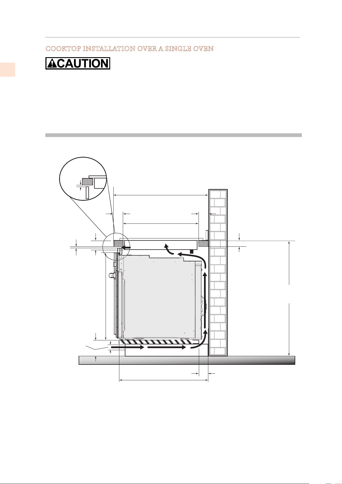
COOKTOP INSTALLATION OVER A SINGLE OVEN
Use the countertop opening dimensions that are given with these instructions.
The cooktop may be installed over a single oven. The oven must exhaust out of the cooktop
enclosure.
The cooktop should be centered over the oven.
The cooktop and the oven must be installed according to each specific installation instruction.
B
A
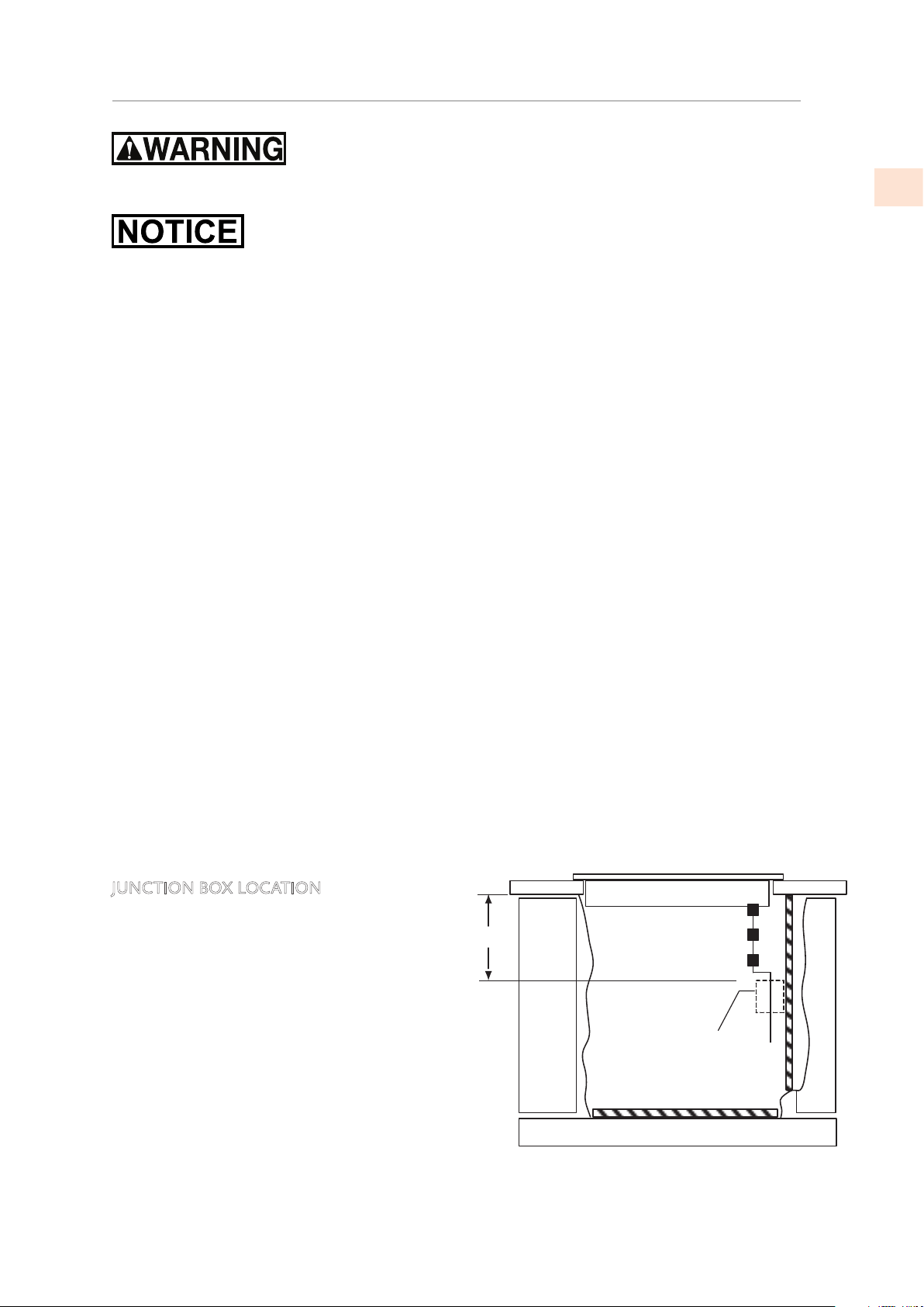
JUNCTION BOX LOCATION
The ELECTRICAL CONDUIT is 4-1/2 feet
[1.37 m] long. DO NOT CUT THIS CONDUIT.
The junction box must be located where it
will allow considerable slack in the conduit for
serviceability.
A) Place junction box so that the conduit
will easily reach it. Make sure that the
conduit will clear any drawers or other
obstructions.
B) Install junction box so that it can be
reached through the front of the cabinet.
* The ventilation opening is to extend the full length of the cooktop cutout.
4”
[101 mm]
min
24” [610 mm]
min
36”
[915 mm]
25” [635 mm]
min
19-7/16” [494 mm]
3”
[76 mm]
[64mm]
2-1/2”
1/4”
[6mm]
min
2-1/2”
[65 mm]
27-1/4”
[692 mm]
4-3/4”
[120 mm]
1-1/2”
[38 mm]
min
1-5/8”
[40 mm]
max
*1/4”
[6 mm]
min
SINGLE
WALL
OVEN
©2019 Hestan Commercial Corporation
9
EN
Disconnect power before servicing the product. Failure to do so could result in death or
electrical shock.
Your cooktop can use 200-240V at 50 or 60 Hz.
The connection leads are 3x8 AWG copper.
This cooktop does not require a neutral connection. If the cooktop is to be completely enclosed
in a cabinet, feed the cooktop cable through the opening in the cabinet.
Make the electrical connection following the appropriate steps for your installation.
The 3/4” flexible conduit is 4-1/2 feet long [1.37 m] located at the right rear of the cooktop
housing. Do not cut the conduit. It should be connected directly into a junction box with a U.L -
or CSA - listed conduit connector.
• A dedicated time-delay fuse or circuit breaker is recommended.
• Do not ground to a gas pipe. Do not have a fuse in the grounding circuit.
• Both supply (phase) lines must be protected by fuses or a circuit breaker.
A three-wire, single-phase, 200-240 V, 60 Hz electrical system (properly circuit protected to meet
local codes of NFPA No.70 must be provided. The unit must be properly grounded in accordance
with local wiring codes. The chart on page2 recommends the minimum circuit protector size
if the appliance is the only unit on the circuit.
If smaller sizes of wire are used, the unit efficiency will be reduced and a fire hazard may be
created. It is advisable that the electrical wiring and hookup be accomplished by a competent
electrician.
NFPA
National Fire Protection Association
1 Batterymarch Park
Quincy, Massachusetts
02169-7471
USA
COOKTOP INSTALLATION
(CONT.)
COOKTOP INSTALLATION OVER A SINGLE OVEN
Use the countertop opening dimensions that are given with these instructions.
The cooktop may be installed over a single oven. The oven must exhaust out of the cooktop
enclosure.
The cooktop should be centered over the oven.
The cooktop and the oven must be installed according to each specific installation instruction.
B
A
JUNCTION BOX LOCATION
The ELECTRICAL CONDUIT is 4-1/2 feet
[1.37 m] long. DO NOT CUT THIS CONDUIT.
The junction box must be located where it
will allow considerable slack in the conduit for
serviceability.
A) Place junction box so that the conduit
will easily reach it. Make sure that the
conduit will clear any drawers or other
obstructions.
B) Install junction box so that it can be
reached through the front of the cabinet.
ELECTRICAL CONNECTIONS
Figure 9. Location of electrical connection

©2019 Hestan Commercial Corporation
10
EN
ELECTRICAL CONNECTIONS
(CONT.)
This appliance is manufactured with a green ground wire connected to the cooktop chassis. After
making sure that the power has been turned off, connect the flexible conduit from the cooktop to
the junction box using a U.L. listed conduit connector. The instructions provided below present
the most common way of connecting the cooktop. Your local codes and ordinances, of course, take
precedence over these instructions. Complete electrical connections according to local codes and
ordinances.
RISK OF ELECTRIC SHOCK. The frame is grounded to neutral of appliance through a link.
Grounding through the neutral conductor is prohibited for new branch circuit installations (1996
NEC); mobile homes, and recreational vehicles, or in an area where local codes prohibit grounding
through the neutral conductor.
4-WIRE BRANCH CIRCUIT
1) Connect the green ground wire from the
cooktop to the ground wire in the junction
box (bare or green colored wire)
2) Connect the red and black leads from the
cooktop to the corresponding leads in the
junction box.
3) Terminate and insulate the neutral (gray or
white colored wire) in the junction box.
Red wires
Bare or green wires
3-Wire cable from cooktop
Twist-on
connector
Black wires
U.L. - or CSA-listed conduit connector
Junction box
White wire
Cable from power supply
3-WIRE BRANCH CIRCUIT
Where local codes allow the connection of
ground wire from the cooktop to the branch
circuit neutral wire (gray or white colored wire)
proceed as follows:
1) If local codes permit, connect the green
GROUND wire from the cooktop to the
branch circuit neutral wire (gray or white
colored wire).
2) Connect the red and black leads from the
cooktop the corresponding leads in the
junction box.
Where local codes permit connecting the
frame-ground conductor to the neutral (white)
junction box wire.
(Not used for Canadian installations)
Cable from power supply
Red Wires
White Wire
Bare or green wires
3-Wire cable from cooktop
Junction box
Twist-on connector
Black wires
UL-or CSA-listed conduit connector
©2019 Hestan Commercial Corporation
11
EN
FINAL SETUP
CLEANUP, VERIFY POWER
Remove any final packaging materials and protective film from all exterior areas.
Check the electrical requirements for the correct electrical supply and that the cooktop is properly
grounded.
Check power at the junction box wires using a voltmeter having a range of 0-250 VAC.
• A 240 Volt supply should read 220 to 240 Volts between the black and red wires (Line to Line).
• A 208 Volt supply should read 190 to 208 Volts between the black and red wires.
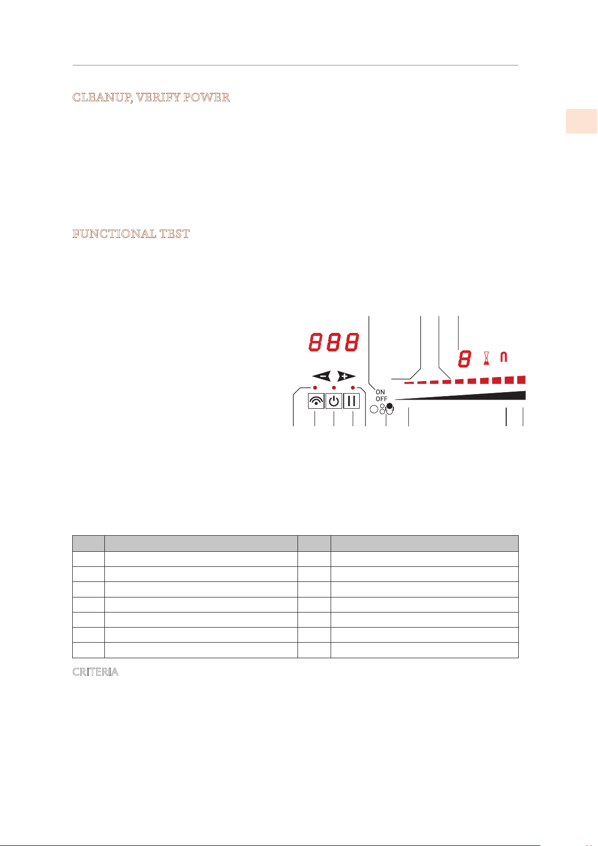
FUNCTIONAL TEST
The following test will confirm that the cooktop is working correctly.
1) Fill an induction-capable cookware piece with 1/2 - 1” [1.2-2.5 cm] of water and place it on one
of the cooking zones.
2) Switch the Control ON by touching the
Power key (1).
3) Touch the zone [ON/OFF] key (13) for
the cook zone where the cookware is.
4) Touch the power slider for that zone
and set it to a level between 3 and 9.
5) Observe that the display responds to
the power setting, and observe that the
cookware begins to heat up.
6) Touch the ON/OFF key (13) for that
zone to turn it off.
7) Touch the Power key (1) to turn the
cooktop off.
Item Function Item Function
1 Power key 8 Power slider - maximum power
2 Connectivity key 9 Select Power Booster
3 Connectivity indicator 10 Cooking zone level display
4 Pause key 11 Power level indicator
5 Pause / Recall indicator 12 Cooking zone indicator
6 Graphic indicating controlled zone 13 Cooking zone ON/OFF
7 Power slider - minimum power
CRITERIA
If the controls respond as described and the cookware heats up, then the test is successful.
Figure 10. Cooktop controls
3 4 5 6 7
1011
2
12
1 8 9
13
min
ON

©2019 Hestan Commercial Corporation
12
EN
SERVICE
All warranty and non-warranty repairs should be performed by qualified service personnel. To
locate an authorized service agent in your zone, contact your Hestan dealer, local representative,
or Hestan. Before you call, please have the model number and serial number information ready.
Hestan Commercial Corporation
3375 E. La Palma Avenue
Anaheim, CA 92806
(888) 905-7463
PARTS LIST
Please visit the Hestan website to access the parts list for your Hestan Indoor product:
www.hestanhome.com.
©2019 Hestan Commercial Corporation
FR
LISEZ ATTENTIVEMENT ET COMPLÈTEMENT CES INSTRUCTIONS AVANT D’INSTALLER
OU D’UTILISER VOTRE APPAREIL AFIN DE RÉDUIRE LES RISQUES D’INCENDIE, DE
BRÛLURE OU D’AUTRES BLESSURES. CONSERVER CE MANUEL POUR RÉFÉRENCE
FUTURE.
DÉFINITIONS DE SÉCURITÉ
INSTALLATEUR: LAISSER CE MANUEL AVEC LE PROPRIÉTAIRE DE
L’APPAREIL.
PROPRIÉTAIRE: CONSERVEZ CE MANUEL POUR RÉFÉRENCE FUTURE.
Ne pas entreposer ni utiliser de I’essence ni d’autres vapeurs ou liquides
inflammables dans Ie voisinage de l’apparell, ni de tout autre appareil.
L’installation et l’entretien doivent être effectués par un installateur qualifié, ou
une agence de service.
NE PAS RÉPARER NI REMPLACER DES PIÈCES DE I´APPAREIL À MOINS
QUE CELA NE SOIT EXPRESSÉMENT RECOMMANDÉ DANS LE MANUEL.
TOUTE INSTALLATION, RÉPARATION OU MAINTENANCE INADÉQUATE
PEUT ENTRAÎNER DES BLESSURES OU DES DOMMAGES MATÉRIELS.
CONSULTER CE MANUEL POUR OBTENIR DES CONSEILS SUR LA FAÇON DE
PROCÉDER. TOUS LES TRAVAUX D‘ENTRETIEN DOIVENT ÊTRE CONFIÉS À
UN TECHNICIEN QUALIFIÉ.
L’INOBSERVATION DES INFORMATIONS DONNÉES DANS CE
MANUEL PEUT ENTRAÎNER UN INCENDIE OU UNE EXPLOSION
DE NATURE À CAUSER DES DÉGÂTS MATÉRIELS ET DES
BLESSURES GRAVES, VOIRE MORTELLES.
CECI INDIQUE QUE L’INOBSERVATION DE CET AVERTISSEMENT
PEUT ENTRAÎNER DES BLESSURES GRAVES VOIRE MORTELLES.
CECI INDIQUE QUE L’INOBSERVATION DE CET AVERTISSEMENT
PEUT ENTRAÎNER DES BLESSURES MINEURES OU MODÉRÉES.
CECI INDIQUE QUE L’INOBSERVATION DE CET AVERTISSEMENT
PEUT ENTRAÎNER DES DOMMAGES DE L’APPAREIL OU DES
DÉGÂTS MATÉRIELS.
FR
©2019 Hestan Commercial Corporation
1
Lorsqu’elle est correctement entretenue, votre appareil Hestan fournira un service sûr et fiable
pendant de nombreuses années.
Lors de l’utilisation de cet appareil, des pratiques de sécurité de base doivent être suivies comme
indiqué ci-dessous.
IMPORTANT: Conservez ces instructions pour l’utilisation de l’inspecteur électrique local.
INSTALLATEUR: Veuillez laisser ces instructions d’installation avec le propriétaire.
PROPRIÉTAIRE: Veuillez conserver ces instructions d’installation pour référence future.
N’installez PAS cet appareil à l’extérieur.
PRÉCAUTIONS DE SÉCURITÉ - AVANT DE COMMENCER
RISQUE DE CHOC ÉLECTRIQUE
Débranchez l’alimentation avant d’installer ou d’entretenir l’appareil. Ne pas le
faire peut entraîner la mort ou un choc électrique.
MISE À LA TERRE ÉLECTRIQUE
Cet appareil doit être mis à la terre. La mise à la terre réduit le risque de choc électrique en
cas de court-circuit. Lisez la section BRANCHEMENTS ÉLECTRIQUES de ce manuel pour des
instructions complètes.
NE PAS broyer sur un tuyau de gaz.
N’utilisez PAS de rallonge avec cet appareil.
N’ayez PAS de fusible dans le circuit NEUTRE ou TERRE. Un fusible dans le circuit NEUTRE ou
MISE A LA TERRE pourrait entraîner un choc électrique.
TABLES DES MATIERES
1 PRÉCAUTIONS DE SÉCURITÉ - AVANT DE COMMENCER
2 NUMÉROS DE MODÈLE
2 PLAQUE SIGNALÉTIQUE
2 RESPECT DE LA RÉGLEMENTATION ET DES CODES EN VIGUEUR
3 DIMENSIONS DU PRODUIT ET EXIGENCES DE DÉCOUPE
6 INSTALLATION DE LA TABLE DE CUISSON
9 CONNEXIONS ELECTRIQUES
11 CONFIGURATION FINAL
12 LISTE DES PIÈCES
12 SERVICE
©2019 Hestan Commercial Corporation
2
FR
NUMÉROS DE MODÈLE
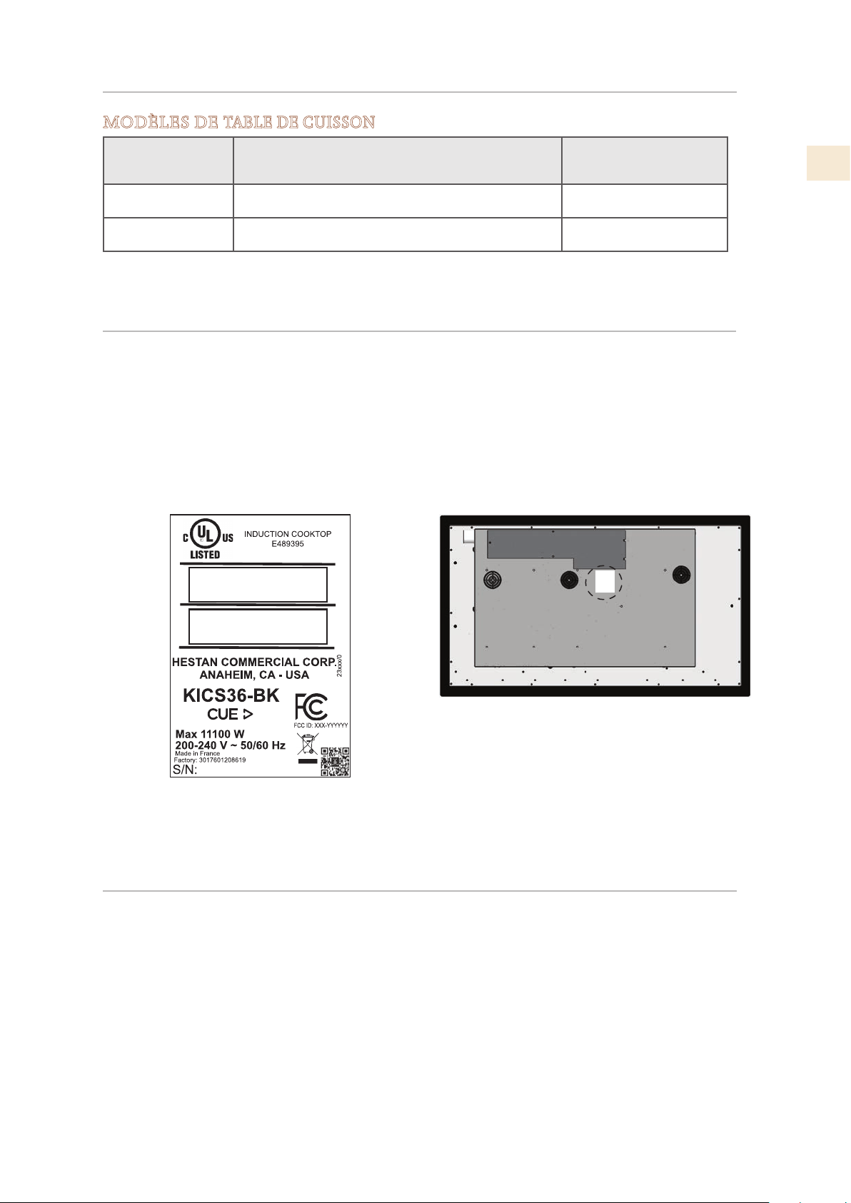
PLAQUE SIGNALÉTIQUE
La plaque signalétique fournit des informations importantes sur cet appareil Hestan telles que le
numéro de série, le numéro de modèle et la classification électrique.
La plaque signalétique est située sous l’unité.
Si une réparation est nécessaire, contactez le service clientèle de Hestan en indiquant les numéros
de modèle et de série sur la plaque.
RESPECT DE LA RÉGLEMENTATION ET DES CODES EN VIGUEUR
Plaque signalétique
MODÈLES DE
TABLE DE CUISSON
NO. MODÈLE DESCRIPTION
DISJONCTEUR
REQUIS
KICS30 Table de cuisson à induction Smart de 30 po 40 Ampères
KICS36 Table de cuisson à induction Smart de 36 po 50 Ampères
L’installation de cet appareil de cuisson doit être effectuée conformément aux codes locaux. En
l’absence de tels codes, installer cet appareil conformément au National Electrical Code et les codes
locaux.
Tous les composants électriques doivent mis à la terre conformément aux codes locaux ou, en
l’absence de tels codes, au National Electrical Code ANSI/NFPA 70 ou au Code national de
l’électricité du Canada CSA C22.1.
Figure 1. Plaque signalétique typique
FR
©2019 Hestan Commercial Corporation
3
DIMENSIONS DU PRODUIT ET EXIGENCES DE DÉCOUPE
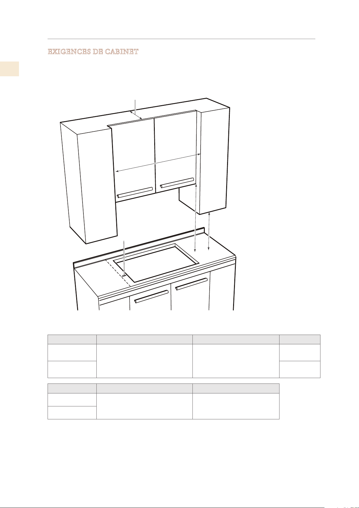
EXIGENCES DE CABINET
Pour éliminer les risques de brûlures ou d’incendie en atteignant les unités de surface chauffées, les
unités de rangement des armoires situées au-dessus des unités de surface doivent être évitées. Si le
rangement de l’armoire doit être fourni, le risque peut être réduit en installant un capot qui dépasse
horizontalement d’au moins 5 po [12,7 cm] du fond des armoires.
Modèle
A B C
KICS30
30 po [76,2 cm] min. du plan de
travail à la surface non protégée au-
dessus, ou selon les exigences de la
hotte de ventilation. *
18 po [45,7 cm] hauteur min.
du plan de travail au meuble la
plus proche de chaque côté de
l’appareil.
30 po
[76,2 cm] min
KICS36
36 po
[91,4 cm] min
Modèle
D E
KICS30
2 po [5,1 cm] min. espace libre entre
l’ouverture et la paroi latérale à
gauche ou à droite de l’appareil. **
13 po [33 cm] profondeur
d’armoires suspendues non
protégées.
KICS36
* 30 po [76,2 cm] de dégagement minimum entre le dessus de la surface de cuisson et le fond d’une
armoire en bois ou en métal non protégée.
** Il est permis de monter la table de cuisson aussi près que 2 po [5,1 cm] d’une armoire ou d’un mur
d’un côté. L’autre côté doit être dégagé.
B
A
C
D
E
LES REVETEMENTS DES
MEUBLES ET LE PLAN DE
TRAVAIL DOIVENT RESISTER A
UNE CHALEUR DE 200°F [93ºC]
Figure 2. Dégagements de cabinet
©2019 Hestan Commercial Corporation
4
FR
AVANT DE COMMENCER
N’installez pas la table de cuisson au-dessus d’un four non ventilé ou d’un lave-vaisselle.
La table de cuisson mesure 2-1/2 po [6,4 cm] de profondeur et nécessite un dégagement d’au moins
1 po [2,5 cm] en dessous.
Si un tiroir est directement sous la table de cuisson, elle doit être résistante à la chaleur. Un tel
tiroir doit être placé / disposé de sorte que rien ne puisse être tiré du tiroir dans les ventilateurs de
ventilation de l’appareil.
CONSEILS IMPORTANTS DE PRÉPARATION
Biseautez tous les bords exposés du contre-plaqué décoratif pour empêcher qu’ils ne s’écaillent.
Arrondissez les quatre coins de la découpe et limez le pourtour pour que les bords soient lisses et
que les coins ne se fissurent pas. Utilisez une mèche de 1/4 po [6,3 mm] ou 3/8 po [9,5 mm] pour
percer les trous à chaque angle.
Si les bords ne sont pas lisses, l’intérieur des coins n’est pas arrondi et l’encastrement a été forcé, il
est possible que le contre-plaqué du plan de travail se fendille.
Si le matériau du comptoir est sensible à l’humidité, les bords coupés doivent être scellés avec un
scellant approprié. Tous les matériaux et les adhésifs doivent pouvoir résister à des températures
allant jusqu’à 200° F [93° C].
La boîte de jonction doit être accessible avec la table de cuisson en place.
Pour des raisons de service, il est conseillé d’avoir suffisamment d’accès au bas de la table de cuisson
pour pouvoir la soulever.
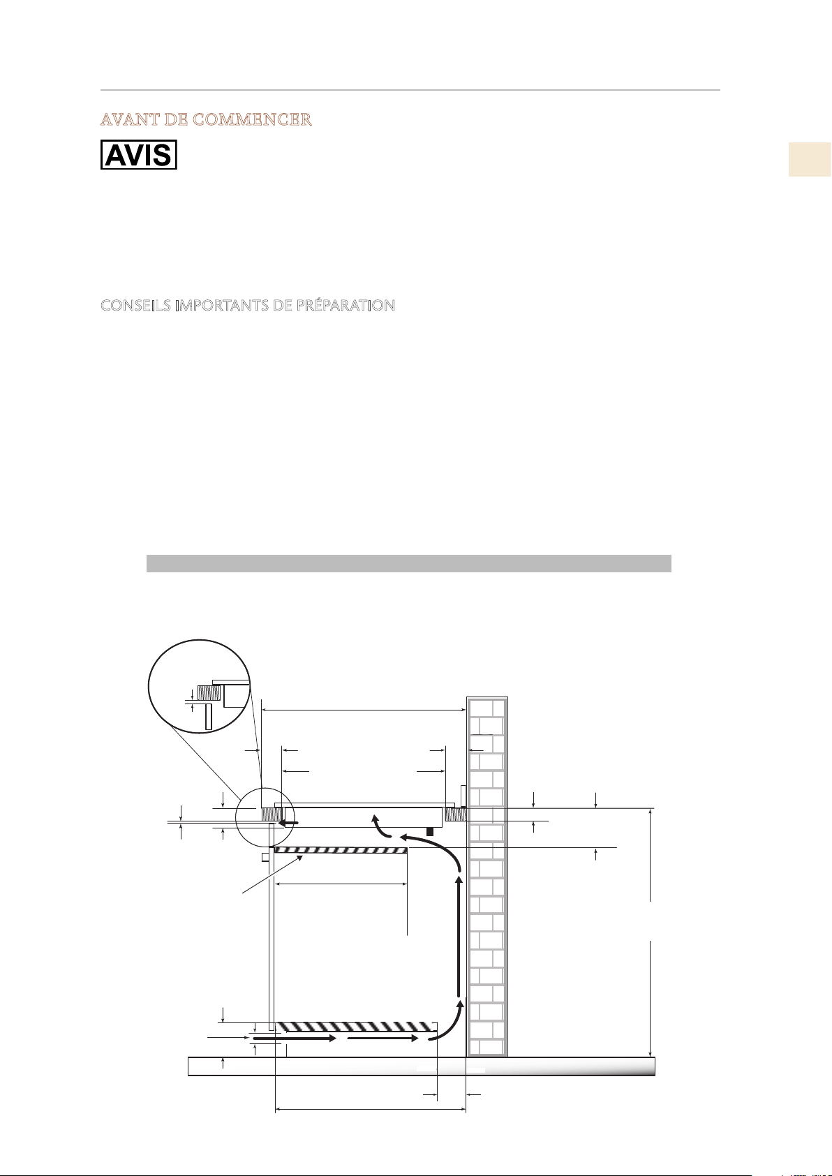
DIMENSIONS DU PRODUIT ET EXIGENCES DE DÉCOUPE
(SUITE)
min
DÉGAGEMENTS VERTICAUX
* L’ouverture d’aération doit être équivalente à la longueur de l’ouverture d’installation de la table de cuisson.
25 po [635 mm]
min
2-1/2 po
[64mm]
3 po
[76 mm]
2-1/2 po
[65 mm]
1-5/8 po
[40 mm]
max
1/4 po
[6 mm]
min
36 po
[915 mm]
24 po [610 mm]
15-3/4 po
[400 mm]
5 po
[127 mm]
min
*1/4 po
[6 mm]
min
19-7/16 po [494 mm]
1-1/2 po
4-3/4 po
[120 mm]
[38 mm]
min
4 po
[101 mm]
min
Cloison
FR
©2019 Hestan Commercial Corporation
5
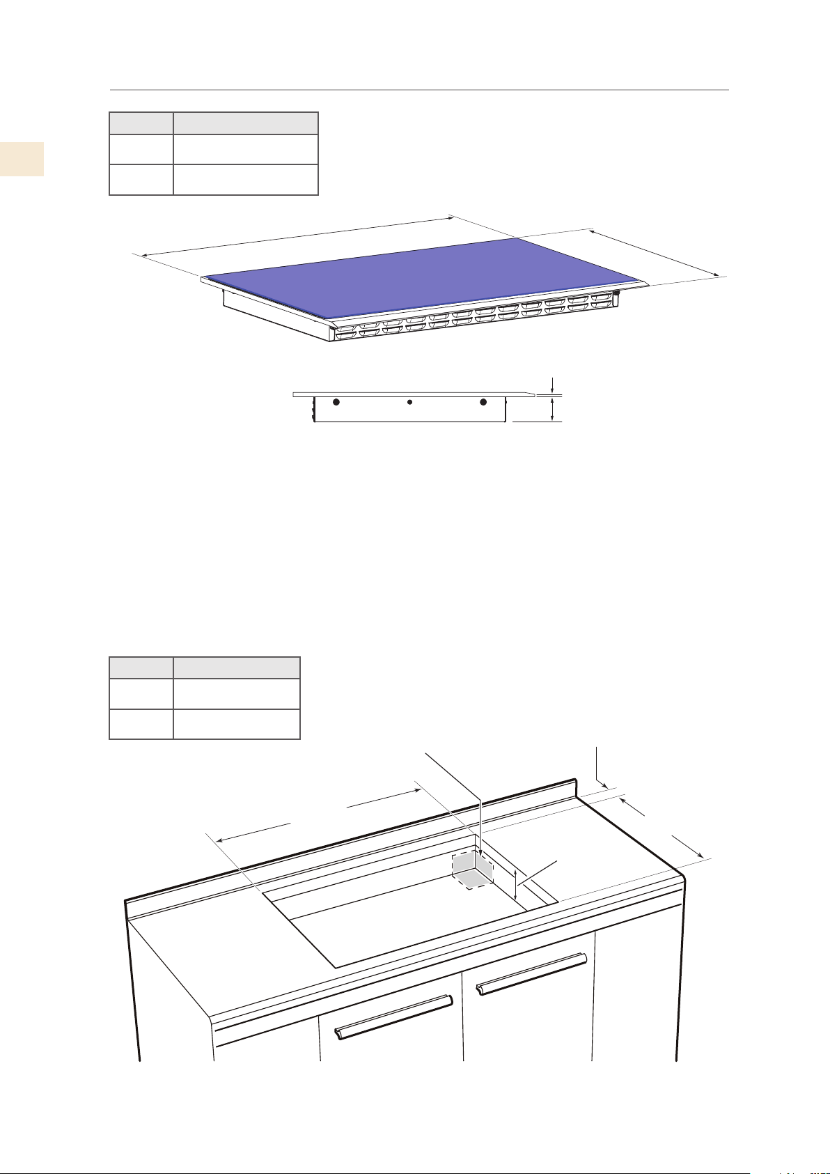
DIMENSIONS DU PRODUIT ET EXIGENCES DE DÉCOUPE
(SUITE)
Modèle W
KICS30 30-5/16 po [77 cm]
KICS36 36-5/32 po [91,8 cm]
Modèle F
KICS30 28-3/8 po [72 cm]
KICS36 34-1/4 po [87 cm]
Figure 3. Dimensions de la Table de Cuisson
21
- ¾ po
[55.2 cm]
2-½ po
[6.4 cm]
3/8
po
[9.5 mm]
W
2” [5.1 cm]
3-½” [8.9 cm]
min. depth
HOLE FOR
POWER CABLE
ENCLOSURE
BOTTOM
(OPTIONAL)
F
19-¼” [48,9 cm]
MIN. CLEARANCE
Figure 4. Dimensions de découpe
©2019 Hestan Commercial Corporation
6
FR
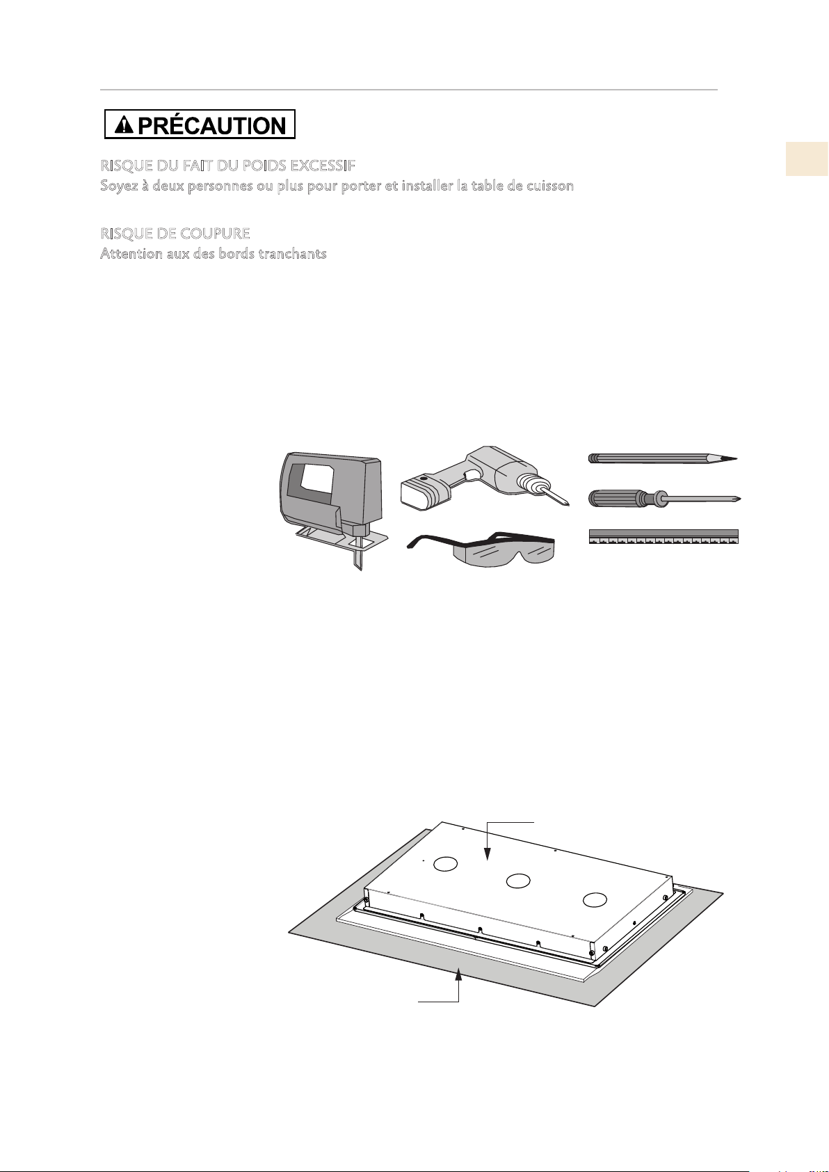
INSTALLATION DE LA TABLE DE CUISSON
RISQUE DU FAIT DU POIDS EXCESSIF
Soyez à deux personnes ou plus pour porter et installer la table de cuisson. Sinon, vous risquez de
vous blesser au dos ou de subir d’autres blessures.
RISQUE DE COUPURE
Attention aux des bords tranchants. Portez des gants de protection ou utilisez les extrémités en
polystyrène lorsque vous transportez le produit. Ne pas faire preuve de prudence peut entraîner des
blessures légères ou des coupures.
Toujours consulter le fabricant du plan de travail pour les instructions spécifiques.
Bien vérifier que le plan de travail est carré et de niveau et assurez-vous qu’aucun élément structurel
n’interfère avec l’espace requis.
Préparez la découpe conformément aux instructions (voir les dimensions de la découpe).
Assurez-vous que les éléments suspendus, le plan de travail et les meubles situées autour de la table de
cuisson peuvent résister à la chaleur (jusqu’à 200°F / 93°C).
ÉTAPE 1
Enlevez les matériaux d’emballage et la documentation de la table de cuisson avant de commencer
l’installation. Lisez attentivement ce manuel d’installation avant de commencer.
ÉTAPE 2
Placez une serviette
ou un chiffon sur la
surface de travail. Placez
l’appareil face cachée sur
la zone protégée.
BOÎTIER DE L'APPAREIL
SERVIETTE
Figure 6. Protéger la surface
Figure 5. Outils nécessaires
FR
©2019 Hestan Commercial Corporation
7
INSTALLATION DE LA TABLE DE CUISSON
(SUITE)
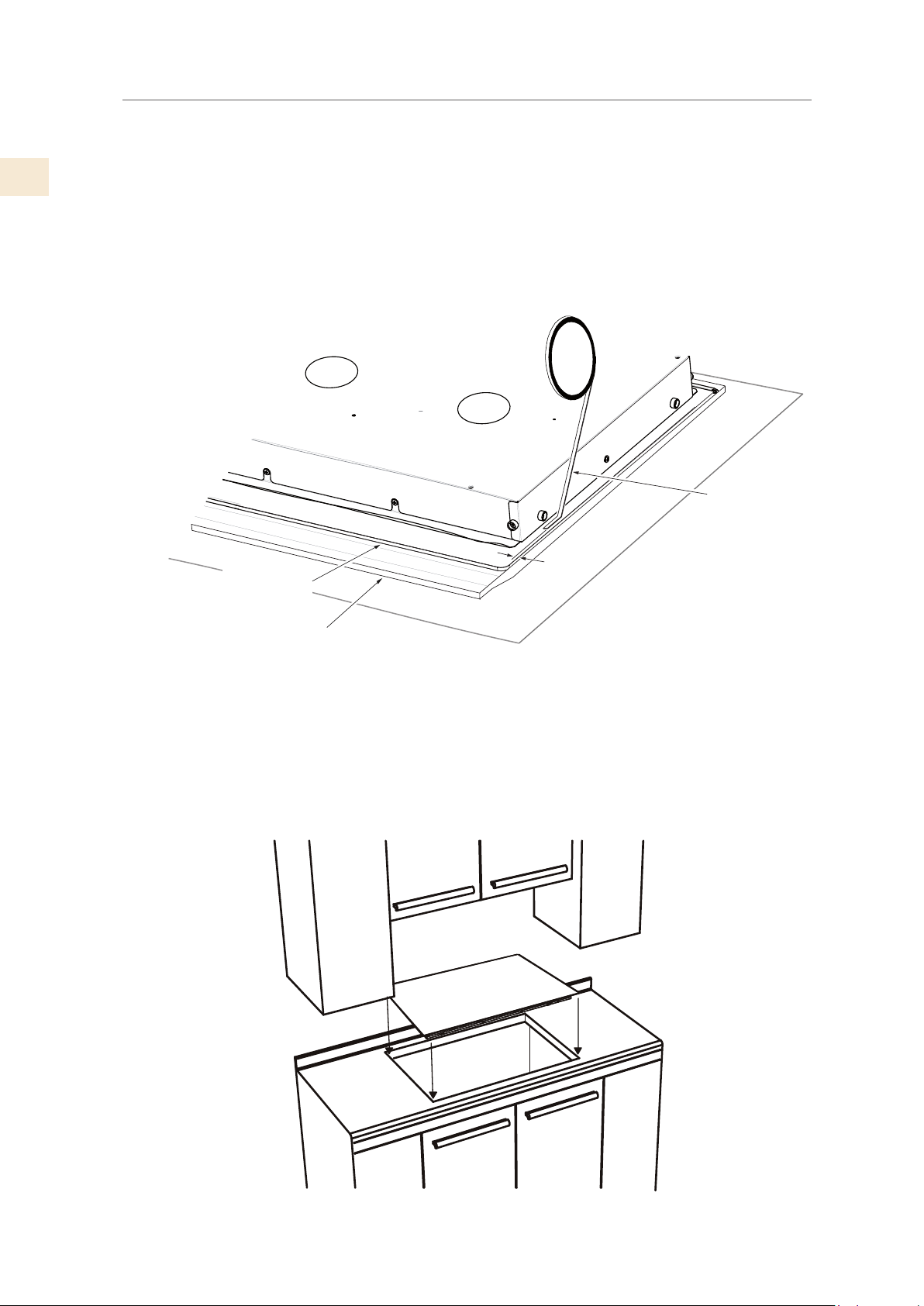
ÉTAPE 3
Un ruban adhésif est fourni pour sceller la table de cuisson au comptoir. Appliquez cette adhésif
sur le dessous de la vitre de la table de cuisson entre le corps de la table de cuisson et le bord
intérieur du cadre.
Il devrait y avoir environ 3/32 po [2 mm] entre le bord du ruban et le bord du verre. Utilisez le
ruban autour du périmètre de verre entier.
Le ruban adhésif fourni avec l’appareil permet d’éviter toute infiltration dans le meuble. Couper les
extrémités de la adhésif de sorte qu’ils se rencontrent sans lacunes.
ÉTAPE 4
Faites une dernière vérification pour vous assurer que tous les dégagements requis sont respectés.
Passez le câble dans l’armoire si nécessaire. Insérez la table de cuisson centre de l’ouverture de la
découpe. Vérifiez que le bord avant de l’appareil est est parallèle à la plan de travail .
BOÎTIER DE L'APPAREIL
RUBAN
ADHÉSIF
VERRE DE LA TABLE
DE CUISSON
CADRE METALLIQUE
2 mm
Figure 7. Appliquer du ruban adhésif
Figure 8. Placer la table de cuisson
©2019 Hestan Commercial Corporation
8
FR
INSTALLATION DE LA TABLE DE CUISSON
(SUITE)
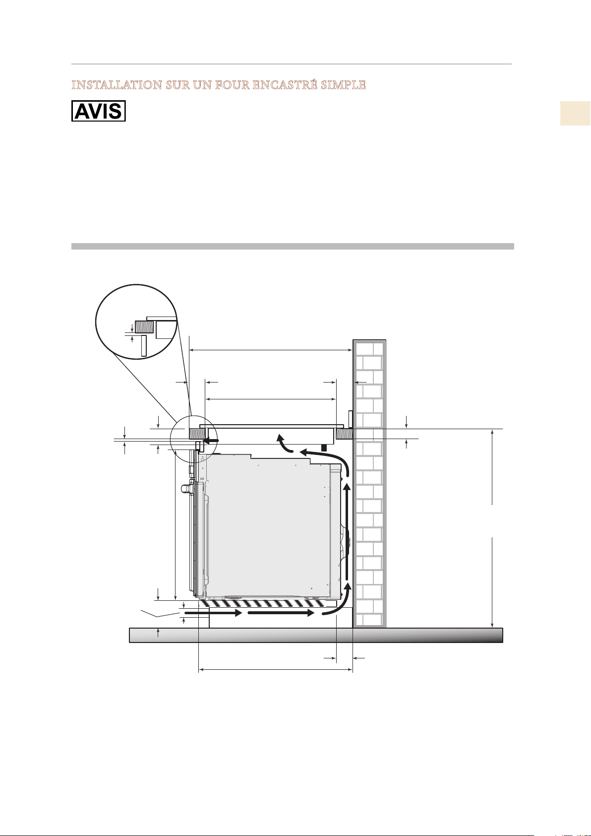
INSTALLATION SUR UN FOUR ENCASTRÉ SIMPLE
Utilisez les dimensions d’ouverture du comptoir fournies avec ces instructions.
La table de cuisson peut être installée sur un seul four. Le four doit sortir de l’enceinte de la table
de cuisson.
La table de cuisson doit être centrée sur le four.
La table de cuisson et le four doivent être installés conformément à chaque instruction
d’installation spécifique.
* L’ouverture d’aération doit être équivalente à la longueur de l’ouverture d’installation de la table de cuisson.
4 po
[101 mm]
min
24 po [610 mm]
min
36 po
[915 mm]
25 po [635 mm]
min
19-7/16 po [494 mm]
3 po
[76 mm]
[64mm]
2-1/2 po
1/4 po
[6mm]
min
2-1/2 po
[65 mm]
27-1/4 po
[692 mm]
4-3/4 po
[120 mm]
1-1/2 po
[38 mm]
min
1-5/8 po
[40 mm]
max
*1/4 po
[6 mm]
min
FOUR
ENCASTRÉ
SIMPLE
FR
©2019 Hestan Commercial Corporation
9
Débranchez l’alimentation avant d’effectuer l’entretien du produit. Ne pas le faire pourrait
entraîner la mort ou un choc électrique.
Votre table de cuisson peut utiliser 200-240V à 50 ou 60 Hz.
Les fils de connexion sont en cuivre 3x8 AWG.
Cette table de cuisson ne nécessite pas de connexion neutre. Si la table de cuisson doit être
complètement enfermée dans une armoire, introduisez le câble de la table de cuisson dans
l’ouverture de l’armoire.
Effectuez la connexion électrique en suivant les étapes appropriées pour votre installation.
Le conduit flexible de 3/4 po est de 4-1/2 pieds de long [1,37 m] situé à l’arrière droit du boîtier de
la table de cuisson. Ne coupez pas le conduit. Il doit être connecté directement dans une boîte de
jonction avec un connecteur de conduit répertorié U.L ou CSA.
• Un fusible temporisé ou un disjoncteur est recommandé.
• Ne mettez pas à la terre une conduite de gaz. Ne pas avoir de fusible dans le circuit de mise à la
terre.
• Les deux lignes d’alimentation (phase) doivent être protégées par des fusibles ou un disjoncteur.
Un système électrique à trois fils monophasé de 200 à 240 volts à 60 cycles (correctement protégé
contre les circuits conformément aux codes locaux de la NFPA n° 70 doit être fourni. L’unité doit
être correctement mise à la terre conformément au code de câblage local. Le tableau de la page 2
recommande la taille minimale du protecteur de circuit si l’appareil est la seule unité sur le circuit.
Si des fils de plus petite taille sont utilisés, l’efficacité de l’unité sera réduite et un risque d’incendie
peut être créé. Il est conseillé que le câblage électrique et le branchement soient effectués par un
électricien compétent.
NFPA
National Fire Protection Association
1 Batterymarch Park
Quincy, Massachusetts
02169-7471
USA
CONNEXIONS ELECTRIQUES
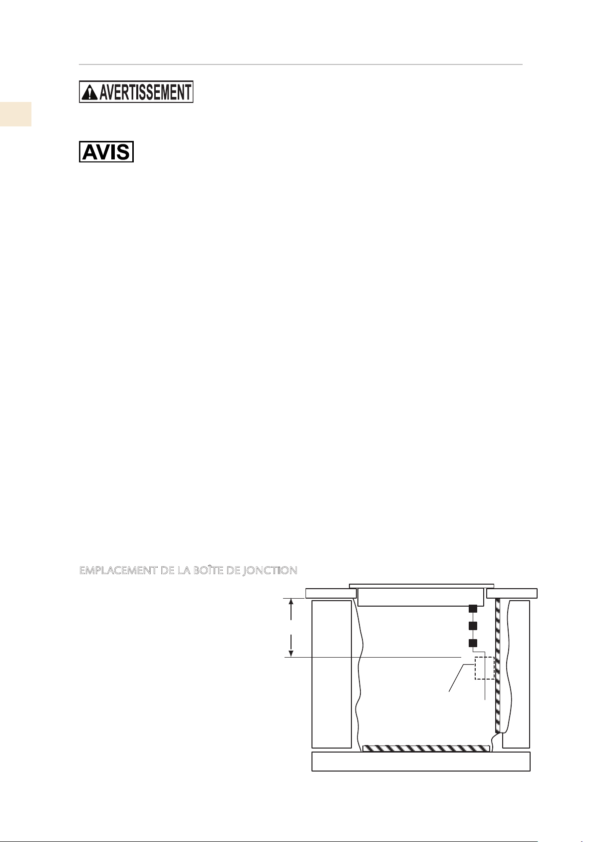
EMPLACEMENT DE LA BOÎTE DE JONCTION
Le CONDUIT ÉLECTRIQUE a une
longueur de 4-1 /2 pieds [1,37 m].
NE COUPEZ PAS CE CONDUIT.
La boîte de jonction doit être située à un
endroit où il y aura un mou considérable
dans le conduit pour l’entretien.
A) Placez la boîte de jonction de sorte
que le conduit puisse facilement
l’atteindre. Assurez-vous que le
conduit dégagera les tiroirs ou autres
obstructions. »
B) Installez la boîte de dérivation de sorte
qu’elle puisse être atteinte par l’avant
de l’armoire.
B
A
Figure 9. Emplacement de la connexion électrique
©2019 Hestan Commercial Corporation
10
FR
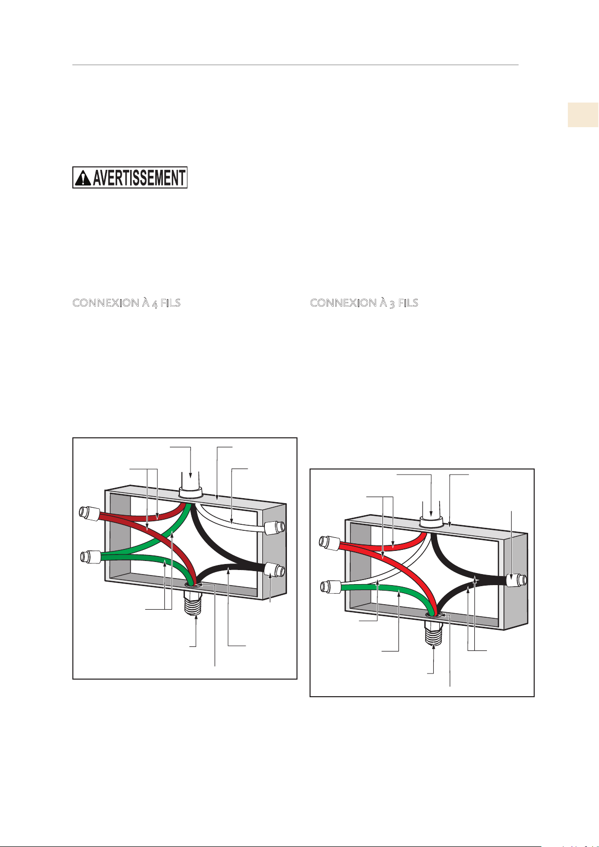
Câbles rouges
Câbles nus ou vert
Câble 3 fils de la table de cuisson
Connecteur
serre-fil
Câble
s noirs
Boite de jonction
Câble
blanc
Connecteur de conduit listé UL ou CSA
Câble de l’alimentation
CONNEXIONS ELECTRIQUES
(SUITE)
Cet appareil est fabriqué avec un conducteur de terre vert connecté au châssis de la table de
cuisson. Après vous être assuré que l’appareil était hors tension, branchez le conduit flexible
depuis le table de cuisson à la boîte de jonction en utilisant un connecteur de conduit U.L. listé.
Les instructions fournies ci-dessous représentent la manière la plus commune de brancher un table
de cuisson. Bien entendu, vos codes et ordonnances locaux ont préséance sur ces instructions.
Effectuez les connexions électriques conformément aux codes et aux ordonnances locaux.
RISQUE DE CHOC ELECTRIQUE. Le cadre est mis à la terre au neutre de l’appareil via un lien.
La mise à la terre par le conducteur neutre est interdite pour les nouvelles installations de circuit
de dérivation (NEC 1996); maisons mobiles et véhicules récréatifs, ou dans une zone où les codes
locaux interdisent la mise à la terre par le conducteur neutre.
CONNEXION À 3 FILS
Lorsque les codes locaux autorisent la
connexion du fil de terre de la table de cuisson
au fil neutre du circuit de dérivation (fil de
couleur grise ou blanche), procédez comme suit:
1. Si les codes locaux le permettent, connectez
le fil vert (TERRE) de la table de cuisson
au fil neutre du circuit de dérivation (fil de
couleur grise ou blanc).
2. Connectez les fils rouge et noir de la table
de cuisson aux fils correspondants dans la
boîte de jonction.
Lorsque les codes locaux autorisent la
connexion du conducteur de mise à la terre
du châssis au fil neutre (blanc) de la boîte de
jonction.
(Non utilisé pour les installations Canadiennes)
Câble blanc
Câbles nus ou vert
Câble 3 fils de la table de cuisson
Câble de l’alimentation
Câbles rouges
Boite de jonction
Connecteur
serre-fil
Câbles noirs
Connecteur de conduit listé UL ou CSA
CONNEXION À 4 FILS
1. Connectez le fil de terre vert du table de
cuisson au fil de terre dans le boîte de
jonction (fil nu ou coloré vert).
2. Connectez les fils rouge et noir de la table
de cuisson aux fils correspondants dans la
boîte de jonction.
3. Terminez et isolez le fil neutre (gris ou
blanc) dans la boîte de jonction.
FR
©2019 Hestan Commercial Corporation
11
CONFIGURATION FINAL
NETTOYAGE, VÉRIFIEZ LA PUISSANCE
Retirez tous les matériaux d’emballage final et le film protecteur de toutes les zones extérieures.
Vérifiez les exigences électriques pour l’alimentation électrique correcte et que la table de cuisson
est correctement mise à la terre.
Vérifiez l’alimentation des fils de la boîte de jonction à l’aide d’un voltmètre de 0-250 VCA.
• Une alimentation de 240 volts devrait lire entre 220 et 240 volts entre les fils noir et rouge
(ligne à ligne).
• Une alimentation de 208 volts devrait lire entre 190 et 208 volts entre les fils noir et rouge.
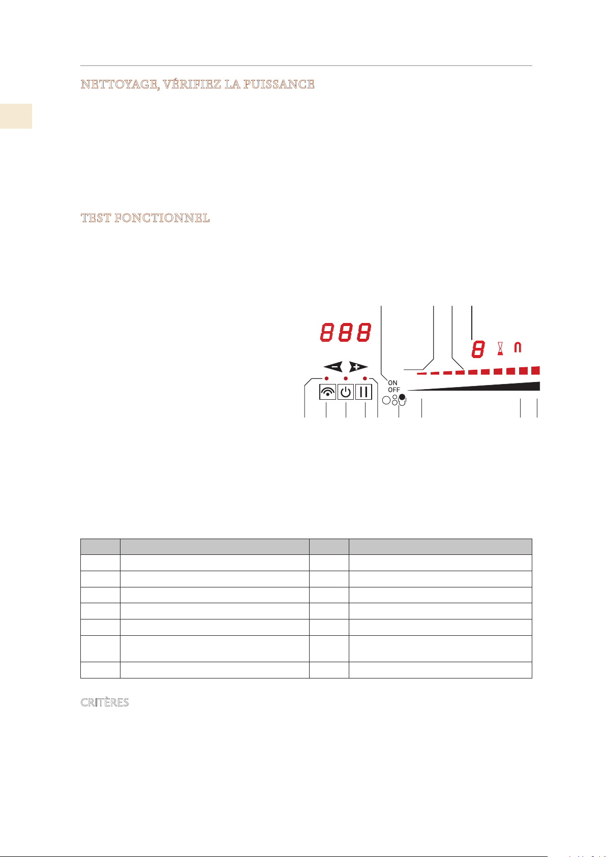
TEST FONCTIONNEL
Le test suivant confirmera que la table de cuisson fonctionne correctement.
1) Remplir un ustensile de cuisson à induction avec 1/2 - 1 po [1.2-2.5 cm] d’eau et placez-la sur
l’une des zones de cuisson.
2) Allumez la commande en appuyant sur
la touche [ON OFF] principal (1).
3) Appuyez sur la bouton de sélection de
zone (13) pour la zone de cuisson où se
trouve l’ustensile de cuisson.
4) Appuyez sur le curseur d’alimentation
de cette zone et réglez-le sur un niveau
compris entre 3 et 9.
5) Observez que l’écran réagit au réglage
de de puissance et que la ustensil de
cuisson commence à chauffer.
6) Appuyez sur la bouton de sélection (13)
de cette zone pour l’éteindre.
7) Appuyez sur la touche [ON OFF] pour
éteindre la table de cuisson.
Article Objectif Article Objectif
1
Bouton de Marche/Arrêt principal 8 Curseur de puissance - puissance maximale
2
Bouton de connectivité 9 Zone du curseur activation Power Booster
3
Indicateur de connectivité 10 Afficheur niveau zone de cuisson
4
Bouton Pause / reprise 11 Indicateur de niveau de puissance
5
Indicateur de pause 12 Indication sur la zone
6
Graphique de la zone de cuisson contrôlée 13
Bouton de sélection de zone Marche/Arrêt
(zone ON / OFF)
7
Curseur de puissance - puissance minimale
CRITÈRES
Si les commandes répondent comme décrit et si l’ustensile de cuisson se réchauffe, le test est réussi.
Figure 10. Commandes de table de cuisson
3 4 5 6 7
1011
2
12
1 8 9
13
min
ON

©2019 Hestan Commercial Corporation
12
FR
LISTE DES PIÈCES
SERVICE
Toutes les réparations dans le cadre ou en dehors de la garantie doivent être effectuées par du
personnel d’entretien qualifié. Pour localiser un réparateur agréé dans la région, s’adresser au
concessionnaire Hestan, au représentant local ou à l’usine. Avant d’appeler, veiller à avoir les
numéros de modèle et de série à portée de la main.
Hestan Commercial Corporation
3375 E. La Palma Avenue
Anaheim, CA 92806
(888) 905-7463
Visiter le site Web Hestan pour consulter la liste des pièces de ce produit:
www.hestanhome.com.

Hestan Commercial Corporation
3375 E. La Palma Avenue
Anaheim, CA 92806
(888) 905-7463
RETAIN THIS MANUAL FOR FUTURE REFERENCE
CONSERVEZ CE MANUEL POUR UNE RÉFÉRENCE FUTURE
©2019 Hestan Commercial Corporation P/N 022209 REV B (A25289-0)