
31-5000497 Rev. 0 02-21 GEA
Installation Instructions
for your new
RAK26TO
Tenant Option Kit
For AJ Series, RAB46*, RAB48*,
RAB26* Wall Sleeve
Before you begin - Read these instructions completely and carefully.
IMPORTANT – OBSERVE ALL GOVERNING CODES AND ORDINANCES.
Note to Installer – Be sure to leave these instructions with the Consumer.
Note to Consumer – Keep these instructions with your Owner’s Manual for future reference.
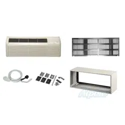
Parts Included
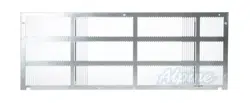
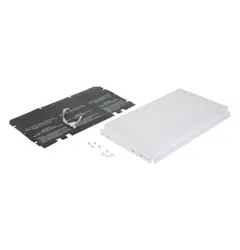
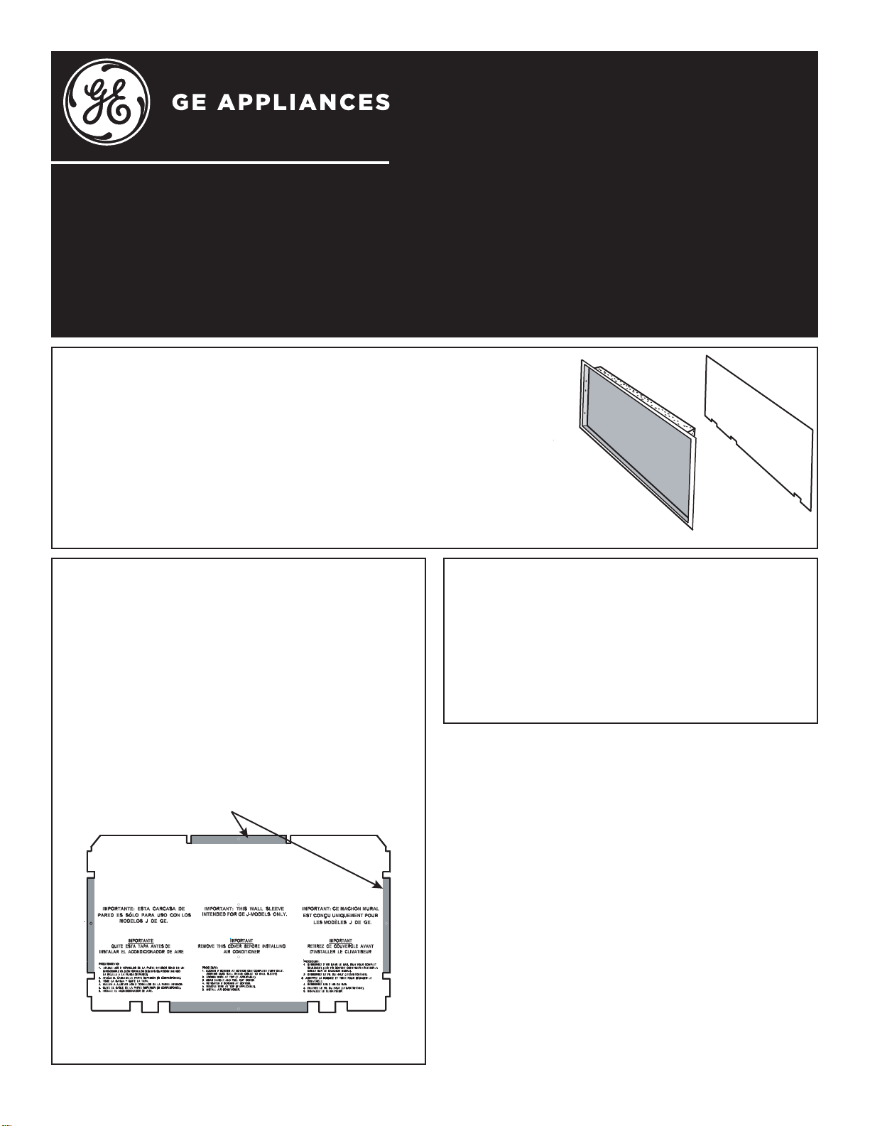
• Interior Panel (with insulation)
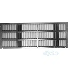
• Exterior Panel (with printed instructions)
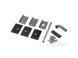
• Screws (4)
• Push Pins (4)
Materials Needed (Field Supplied Parts)
• Phillips Head Screw Driver
• 5/16” Driver (To loosen screws on Rear Grille)
GE is a trademark of the General Electric Company. Manufactured under trademark license.
IMPORTANTE: ESTA CARCASA DE
PARED ES SÓLO PARA USO CON LOS
MODELOS J DE GEA.
IMPORTANTE
QUITE ESTA TAPA ANTES DE
INSTALAR EL ACONDICIONADOR DE AIRE
IMPORTANT
REMOVE THIS COVER BEFORE INSTALLING
AIR CONDITIONER
IMPORTANT
RETIREZ CE COUVERCLE AVANT
D’INSTALLER LE CLIMATISEUR
IMPORTANT: THIS WALL SLEEVE
INTENDED FOR GEA J-MODELS ONLY
IMPORTANT:
CE MACHON MURAL
EST CONÇU UNIQUEMENT POUR
LES MOD
ÉLE
S
J DE GEA.
PROCED
I
MIENTO:
1
.
AFL
OJE LOS 2 TO
R
N
ILLO
S
DE LA PARTE INFERIOR
SÓLO EN UN
GIRO
CO
M
PLETO. (LOS
TORNILLOS D
E
BEN
S
EGUIR SOSTENIENDO
LA
RE
J
I
L
LA
A
L
A
F
U
ND
A
DE PARED).
2.
AF
L
O
JE E
L
C
AB
LE
D
E
L
A
PAR
TE
S
U
P
E
R
IO
R
9SI
C
OR
RES
P
O
ND
E)
.
3
. T
O
ME
L
A
MAN
IJA
Y
QU
I
T
E
LA
TA
P
A
.
4.
V
U
E
LA
A
AJ
U
STAR
L
O
S
2 TO
R
NI
LLOS DE LA PA
R
TE IN
F
ERIOR.
5. QUITE EL CA
B
LE DE LA PARTE SUPERIOR (SI CORRE
SPON
D
E
)
.
6. INST
A
LE
EL
A
CONDICIONADOR DE AI
RE.
PROCEDURE:
1.
LOOSEN 2 SCREWS
A
T B
OT
T
O
M.
ONE C
O
MP
LETE
TURN ON
L
Y.
(SCR
EWS
M
US
T
ST
I
LL RETAIN G
R
I
L
LE TO WAL
L
S
L
EEV
E)
.
2.
LOOSEN WIRE AT TOP (IF
APPLICABLE).
3. G
RAB HANDLE AND PULL OUT COVER.
4.
R
E
TI
G
HT
EN 2 SC
REWS
AT BOT
T
OM.
5.
REMOVE WIRE AT TOP (IF
A
PPLICABLE).
6.
I
N
ST
AL
L
AIR
COND
I
TIONER
PR
OC
E
D
URE:
1
.
D
E
SS
ERRE
Z
2
V
IS DA
NS
L
E
BA
S
, D’UN
T
OU
R
C
O
MP
LE
T
S
E
U
L
E
MENT
.
(L
E
S
VI
S DO
I
V
ENT CONTINUE
R
A RETE
N
I
R
LA
G
R
I
L
L
E
S
U
R
L
E
M
A
NC
H
O
N MU
RA
L).
2.
DESSERR
E
Z LE FIL DU HAUT (LE C
A
S ÉCHÉANT)
.
3. AGRIPPEZ LA POIGNÉE ET TIREZ POUR DÉGAGAR
LE
COUVE
R
CLE.
4. RESSERREZ L
E
S
2
V
IS
D
U BAS
.
5.
E
NLE
V
E
Z
L
E
FIL
D
U
HA
U
T (
LE
CAS ÉCH
É
AN
T
.)
6.
INSTALLEZ LE CLIMA
T
I
S
E
U
R
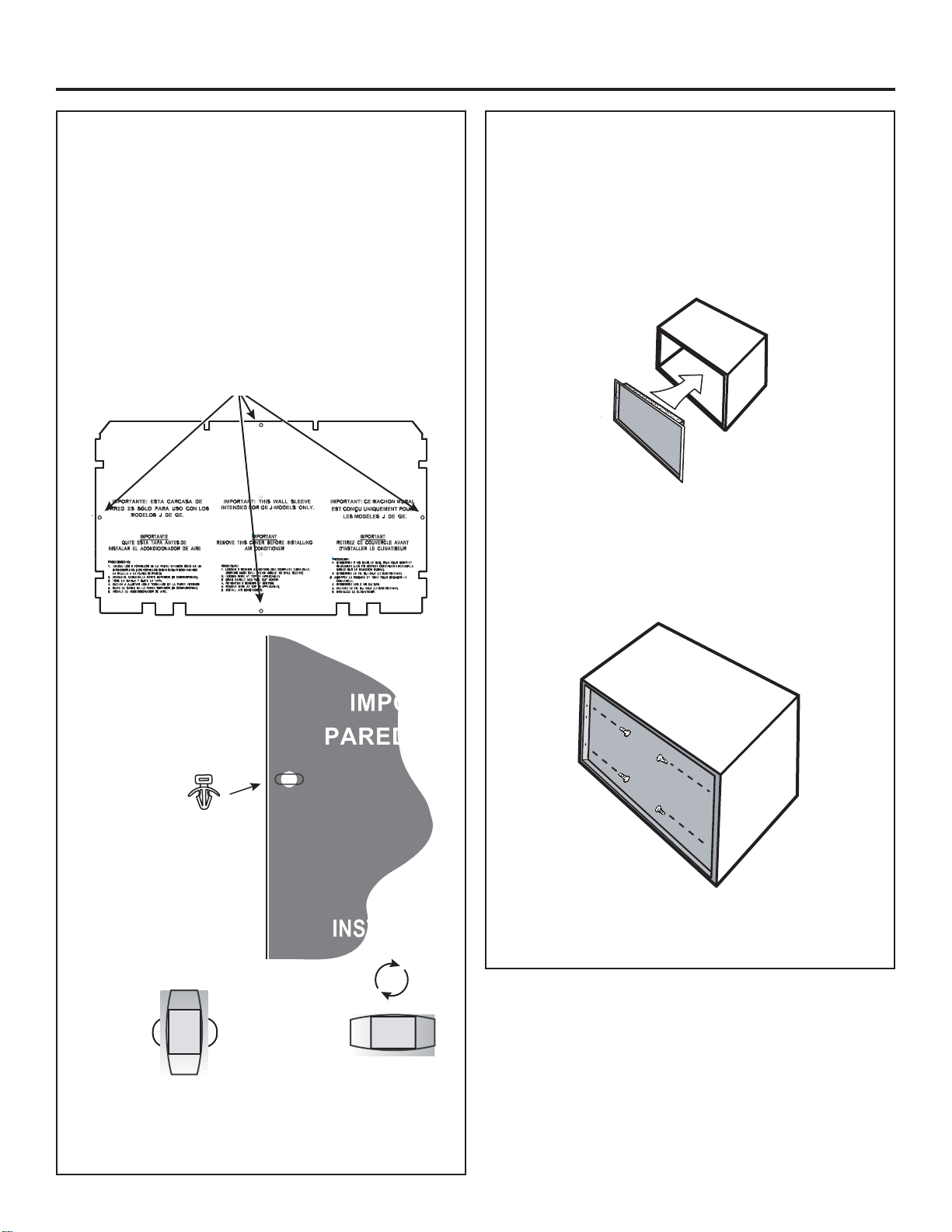
Exterior Panel
Interior Panel
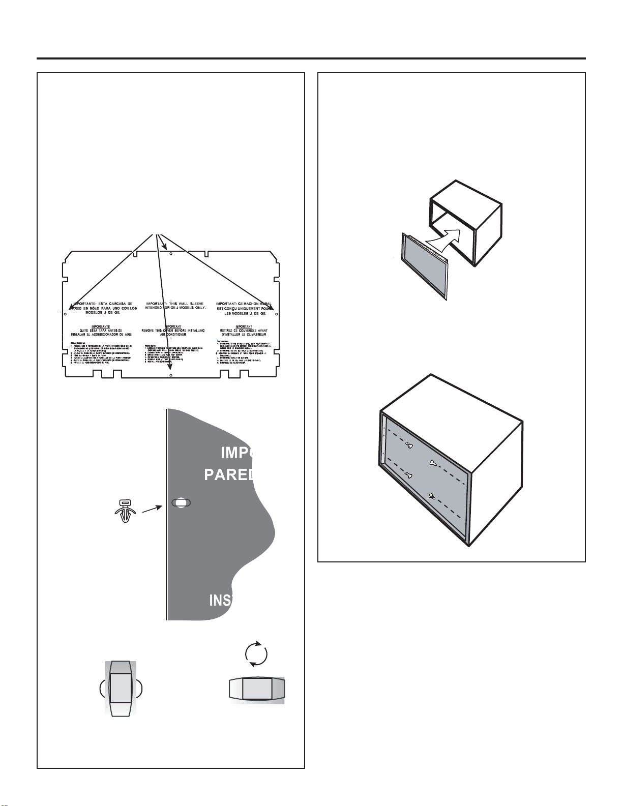
STEP 1:
Installation of Exterior Panel
For RAB46A and RAB48B wall sleeve models
)URPWKHLQVLGHRIWKHVOHHYHORRVHQWKH»๛´
screws, that secure the rear grille to the wall sleeve, 1
complete turn.
2. Place black outdoor cover inside wall sleeve against
WKHUHDUÀDQJH
3. Insert the middle tabs at the top, bottom and sides
RIWKHEODFNRXWGRRUFRYHUEHWZHHQWKHUHDUÀDQJHV
of the sleeve and the outdoor grille to seal out wind
and water.
Insert these four tabs between the rear
ÀDQJHRIWKHVOHHYHDQGWKHRXWGRRUJULOOH
Tabs
STEP 1 (cont):
Installation of Exterior Panel
For RAB46A and RAB48B wall sleeve models
:KHQWKHEODFNRXWGRRUFRYHULV¿WWHGFRUUHFWO\
EHWZHHQVOHHYHÀDQJHVDQGWKHRXWGRRUJULOOH
retighten the 2 grille screws to secure it in place.

2
Installation Instructions
STEP 1 (cont):
Installation of Exterior Panel
For RAB26A wall sleeve models
1. Place black outdoor cover inside the wall sleeve.
0DNHFHUWDLQFRYHULVÀDWDJDLQVWWKHVOHHYHÀDQJHV
at the rear of the wall sleeve.
2. Align the four holes in the black outdoor cover with
WKHKROHVLQWKHVOHHYHÀDQJHV
3. Insert the four push pins provided into the four holes
in the black outdoor cover.
STEP 2:
Installation of Interior Panel
1. Install the Interior Panel into the front of the wall
VOHHYH0DNHVXUHWKDWWKHSDQHOLVSUHVVHG¿UPO\
against the front face of the wall sleeve. The screw
holes in the Interior panel should align with the screw
holes in the wall sleeve.
2. Install the 4 supplied screws to secure the Interior
panel to the wall sleeve. There will be an extra set of
holes in the Interior panel that will not be used. Those
KROHVDUHIRUGLႇHUHQWDSSOLFDWLRQV
Holes for push pins
90º
To hold black outdoor
cover in place insert
the push pin through
the hole in the cover
and into the slot in the
ZDOOVOHHYHÀDQJH
Push pin is locked
into slot in wall
VOHHYHÀDQJH
To remove push pin
rotate it 90 degrees
and pull straight out
Install 4 Screws
Printed in the United States
Instructions d’installation de votre
nouvelle trousse de panneaux
intérieur et extérieur
RAK26TO
pour gaines murales de série AJ,
RAB46*, RAB48* et RAB26*
Avant de commencer - Lisez ces instructions attentivement et en entier.
IMPORTANT – OBSERVEZ TOUS LES CODES ET RÈGLEMENTS EN VIGUEUR.
Note à l’installateur – Assurez-vous de laisser ces instructions au consommateur.
Note au consommateur - Conservez ces instructions avec votre manuel d’utilisation pour consultation ultérieure.
GE est une marque de commerce de General Electric Company. Fabriqué sous licence de marque.
Pièces incluses
• Panneau intérieur (avec isolant)
• Panneau extérieur (avec instructions imprimées)
• Vis (4)
• Boutons poussoirs (4)
Matériel requis (non fourni)
• Tournevis à tête étoilée
• Tournevis 5/16 po (pour desserrer les vis sur la grille arrière)
IMPORTANTE: ESTA CARCASA DE
PARED ES SÓLO PARA USO CON LOS
MODELOS J DE GEA.
IMPORTANTE
QUITE ESTA TAPA ANTES DE
INSTALAR EL ACONDICIONADOR DE AIRE
IMPORTANT
REMOVE THIS COVER BEFORE INSTALLING
AIR CONDITIONER
IMPORTANT
RETIREZ CE COUVERCLE AVANT
D’INSTALLER LE CLIMATISEUR
IMPORTANT: THIS WALL SLEEVE
INTENDED FOR GEA J-MODELS ONLY
IMPORTANT:
CE MACHON MURAL
EST CONÇU UNIQUEMENT POUR
LES MOD
ÉLE
S
J DE GEA.
PROCED
I
MIENTO:
1
.
AFL
OJE LOS 2 TO
R
N
ILLO
S
DE LA PARTE INFERIOR
SÓLO EN UN
GIRO
CO
M
PLETO. (LOS
TORNILLOS D
E
BEN
S
EGUIR SOSTENIENDO
LA
RE
J
I
L
LA
A
L
A
F
U
ND
A
DE PARED).
2.
AF
L
O
JE E
L
C
AB
LE
D
E
L
A
PAR
TE
S
U
P
E
R
IO
R
9SI
C
OR
RES
P
O
ND
E)
.
3
. T
O
ME
L
A
MAN
IJA
Y
QU
I
T
E
LA
TA
P
A
.
4.
V
U
E
LA
A
AJ
U
STAR
L
O
S
2 TO
R
NI
LLOS DE LA PA
R
TE IN
F
ERIOR.
5. QUITE EL CA
B
LE DE LA PARTE SUPERIOR (SI CORRE
SPON
D
E
)
.
6. INST
A
LE
EL
A
CONDICIONADOR DE AI
RE.
PROCEDURE:
1.
LOOSEN 2 SCREWS
A
T B
OT
T
O
M.
ONE C
O
MP
LETE
TURN ON
L
Y.
(SCR
EWS
M
US
T
ST
I
LL RETAIN G
R
I
L
LE TO WAL
L
S
L
EEV
E)
.
2.
LOOSEN WIRE AT TOP (IF
APPLICABLE).
3. G
RAB HANDLE AND PULL OUT COVER.
4.
R
E
TI
G
HT
EN 2 SC
REWS
AT BOT
T
OM.
5.
REMOVE WIRE AT TOP (IF
A
PPLICABLE).
6.
I
N
ST
AL
L
AIR
COND
I
TIONER
PR
OC
E
D
URE:
1
.
D
E
SS
ERRE
Z
2
V
IS DA
NS
L
E
BA
S
, D’UN
T
OU
R
C
O
MP
LE
T
S
E
U
L
E
MENT
.
(L
E
S
VI
S DO
I
V
ENT CONTINUE
R
A RETE
N
I
R
LA
G
R
I
L
L
E
S
U
R
L
E
M
A
NC
H
O
N MU
RA
L).
2.
DESSERR
E
Z LE FIL DU HAUT (LE C
A
S ÉCHÉANT)
.
3. AGRIPPEZ LA POIGNÉE ET TIREZ POUR DÉGAGAR
LE
COUVE
R
CLE.
4. RESSERREZ L
E
S
2
V
IS
D
U BAS
.
5.
E
NLE
V
E
Z
L
E
FIL
D
U
HA
U
T (
LE
CAS ÉCH
É
AN
T
.)
6.
INSTALLEZ LE CLIMA
T
I
S
E
U
R
Panneau
intérieur
ÉTAPE 1:
Installation du panneau extérieur
Pour gaines murales des modèles RAB46A et RAB48B
1. Depuis l’intérieur de la gaine, desserrez les vis 2 5/16
SRTXL¿[HQWODJULOOHDUULqUHVXUODJDLQHG¶XQWRXU
complet.
2. Placez le couvercle extérieur noir à l’intérieur de la
gaine contre le rebord arrière.
3. I nsérez les languettes du milieu dans le haut, le
bas et les côtés du couvercle extérieur noir entre le
rebord arrière de la gaine et la grille extérieure pour
protection contre le vent et l’eau.
Insérez ces quatre languettes entre le rebord
arrière de la gaine et la grille extérieure.
Tabs
ÉTAPE 1 (suite):
Installation du panneau extérieur
Pour gaines murales des modèles RAB46A et RAB48B
4. Une fois le couvercle extérieur noir rentré
correctement entre le rebord de gaine et la grille
H[WpULHXUHUHVVHUUH]OHVYLVGHODJULOOHSRXUOD¿[HU
en place.
31-5000497 Rev. 0 02-21 GEA
Panneau
extérieur
2
Instructions d’installation
ÉTAPE 1 (suite) :
Installation du panneau extérieur
Pour gaine murale de modèle RAB26A
1. Placez le couvercle extérieur noir à l’intérieur de la
gaine murale. Assurez-vous que le couvercle repose à
plat contre le rebord à l’arrière de la gaine.
2. Alignez les quatre trous du couvercle extérieur noir
sur les trous du rebord de la gaine.
3. Insérez les quatres boutons poussoirs (fournis) dans
les quatre trous du couvercle extérieur.
ÉTAPE 2:
Installation du panneau intérieur
1. Installez le panneau intérieur sur le devant de la
gaine murale. Assurez-vous que le panneau est
appuyé fermement contre la face avant de la gaine.
Les trous de vis du panneau intérieur doivent
s’aligner sur les trous de vis de la gaine.
,QVWDOOH]OHVTXDWUHYLVIRXUQLHVSRXU¿[HUOH
panneau intérieursur la gaine. Un ensemble de trous
supplémentaires dans le panneau intérieur ne sera
pas utilisé. Ces trous servent à d’autres applications.
Trous pour boutons poussoirs
90º
Pour maintenir le
couvercle extérieur
noir en place, insérer
le bouton poussoir
à travers le trou du
couvercle puis dans la
fente du rebord de la
gaine murale.
Bouton poussoir
verrouillé dans la fente
du rebord de gaine
Pour retirer le bouton
poussoir, tourner de
90 degrés et tirer
Installer 4 vis
Imprimé aux États-Unis
Instrucciones de Instalación
para su nuevo
RAK26TO
Kit Opcional para el Propietario
de Carcasas de Pared RAB46*,
RAB48*, RAB26* de la Serie AJ
Antes de comenzar – lea estas instrucciones completamente y de forma detenida.
IMPORTANTE – CUMPLA CON TODOS LOS CÓDIGOS Y ORDENANZAS GUBERNAMENTALES.
Nota para el Instalador – Asegúrese de entregar estas instrucciones al Consumidor.
Nota para el Consumidor – Guarde estas instrucciones con su Manual del Propietario para referencia futura.
GE Appliances es una marca de General Electric Company. Fabricado bajo licencia de la marca.
Piezas Incluidas
• Panel Interior (con aislante)
• Panel Exterior (con instrucciones impresas)
• Tornillos (4)
• Pernos de Presión (4)
Materiales Necesarios (Piezas Suministradas de Fábrica)
• Destornillador con Cabeza Phillips
• Destornillador 5/16” (Para aflojar tornillos en la Rejilla Trasera)
IMPORTANTE: ESTA CARCASA DE
PARED ES SÓLO PARA USO CON LOS
MODELOS J DE GEA.
IMPORTANTE
QUITE ESTA TAPA ANTES DE
INSTALAR EL ACONDICIONADOR DE AIRE
IMPORTANT
REMOVE THIS COVER BEFORE INSTALLING
AIR CONDITIONER
IMPORTANT
RETIREZ CE COUVERCLE AVANT
D’INSTALLER LE CLIMATISEUR
IMPORTANT: THIS WALL SLEEVE
INTENDED FOR GEA J-MODELS ONL
Y
IMPORTANT: CE MACHON MURAL
EST CONÇU U
NI
QUEMENT POUR
LES MOD
ÉLES J DE GEA.
PROC
E
D
IMIE
NTO
:
1
.
AFL
O
J
E L
OS
2
T
O
RNIL
LO
S
DE LA
P
ARTE INFERIOR SÓLO EN UN
GIRO COMPLETO. (LOS TORNILLOS DEBEN SEGUIR SOSTENIENDO
LA
REJ
IL
LA
A
L
A
FU
ND
A
D
E PARE
D
)
.
2. AFLO
JE
E
L CABLE DE
LA
P
A
R
TE
S
U
P
ERIO
R
9SI COR
RE
SPON
D
E).
3. TO
ME
L
A
MANIJ
A
Y QUITE LA
T
APA.
4.
VUELA
A AJUSTAR LO
S
2
TO
RNI
LLOS DE LA PARTE INFERIOR.
5. QUITE EL CABLE DE LA PA
R
T
E
SU
P
ERIOR (SI C
O
RRE
SPONDE).
6
.
I
N
STAL
E
E
L
A
C
ON
D
I
C
I
O
NAD
O
R D
E
AI
RE.
PR
O
CE
D
UR
E:
1. LOOSEN 2 SCREWS
A
T
BO
T
TOM. ONE CO
M
P
LET
E
T
U
RN ON
LY
.
(SC
R
E
WS
MUS
T STILL RETAIN GRILLE TO WAL
L
S
LEE
VE
).
2.
LOOSEN W
I
RE AT
TO
P
(
IF
AP
P
LICABLE).
3. G
RAB HANDLE AND PULL OUT COVER.
4. RE
T
IGH
T
E
N
2
SC
REWS
AT BOT
T
OM.
5.
R
E
M
OVE
W
I
R
E
A
T
TOP (IF
A
PPLIC
ABLE).
6.
I
NSTALL AIR CONDITIONER
PROCEDURE:
1.
DESSERREZ 2 VIS DANS LE BAS, D’UN TOUR COMPLET
SE
U
L
E
MEN
T.
(
L
ES
VIS DO
IVENT CONTIN
U
ER A RETENIR LA
GRILLE SUR LE MA
N
CHON MURAL).
2. DESSER
R
EZ LE FIL DU
HAUT (L
E
CA
S
ÉCHÉANT).
3.
A
GRIP
P
E
Z
L
A
PO
I
GNÉE
E
T TI
R
E
Z
P
O
UR
D
É
G
AGA
R
LE
COUVERCLE.
4. RESSER
R
EZ L
ES 2 VIS D
U
B
A
S.
5.
E
N
L
E
VE
Z
LE F
IL
D
U
HAUT
(
LE
CAS ÉCHÉANT.)
6.
I
N
S
T
ALLE
Z
L
E
C
L
I
M
A
TISEUR
Panel Exterior
Panel Interior
PASO 1:
Instalación del Panel Exterior
Para los modelos con carcasa de Pared
RAB46A y RAB48B
'HVGHODSDUWHLQWHULRUGHODFDUFDVDDÀRMHORV
tornillos de 5/16” que aseguran la rejilla trasera a la
carcasa de pared, dando 1 giro completo.
&RORTXHODWDSDH[WHULRUQHJUDGHQWURGHODFDUFDVD
de pared, contra la brida trasera.
3. Inserte las lengüetas intermedias en la parte superior,
inferior y laterales de la tapa exterior negra, entre las
EULGDVWUDVHUDVGHODPDQJD\ODUHMLOODH[WHULRUD¿Q
de aplicar un sellado contra el viento y el agua.
Inserte estas cuatro lengüetas entre la lengüeta
trasera de la carcasa y la rejilla exterior.
Tabs
PASO 1 (cont):
Instalación del Panel Exterior
Para los modelos con carcasa de Pared
RAB46A y RAB48B
4. Cuando la tapa exterior negra se ajuste de forma
correcta entre las bridas de la carcasa y la rejilla
H[WHULRUYXHOYDDDMXVWDUORVWRUQLOORVGHODUHMLOODSDUD
asegurarla en su posición.
5HY*($
Instrucciones de Instalación
Impreso en Estados Unidos
PASO 1 (cont):
Instalación del Panel Exterior
Para los modelos con carcasa de Pared
RAB26A
1. Vuelva a colocar la tapa exterior negra dentro de la
carcasa de pared. Asegúrese de que la tapa quede
plana contra las bridas de pared en la parte trasera
de la carcasa de pared.
$OLQHHORVFXDWURDJXMHURVGHODWDSDH[WHULRUQHJUD
con los agujeros de las bridas de la carcasa.
3. Inserte los cuatro pernos de presión provistos en los
cuatro agujeros de la tapa exterior negra.
PASO 2:
Instalación del Panel Interior
1. Instale el Panel Interior en el frente de la carcasa de
pared. Asegúrese de que el panel sea presionado de
PDQHUD¿UPHFRQWUDODFDUDIURQWDOGHODFDUFDVDGH
pared. Los agujeros de los tornillos del panel interior se
deberán alinear con los agujeros de los tornillos de la
carcasa de pared.
,QVWDOHORVWRUQLOORVVXPLQLVWUDGRVSDUDDVHJXUDUHO
panel interior a la carcasa de pared. Habrá un conjunto
de agujeros adicionales en el panel interior que no
serán usados. Esos agujeros son para diferentes
aplicaciones.
Agujeros para pernos de presión
Para sostener la tapa
exterior negra en su
posición, inserte el perno
de presión a través del
agujero de la tapa y en la
ranura de la brida de la
carcasa de pared.
El perno de presión
está bloqueado en la
ranura de la brida de
la carcasa de pared.
$¿QGHUHWLUDUHO
perno de presión, gire
el mismo 90 grados y
empuje hacia afuera.
Instale los 4 Tornillos
90º