Loading ...
Loading ...
Loading ...
Installation Instructions and Owner’s Manual
Unvented LP-Gas Vent Free Room Heaters
9
CAUTION: Never connect heater directly to the Propane
supply. This heater requires an external regulator (not
supplied). Install the external regulator between the
heater and Propane/LP supply.
IMPORTANT: The installer must supply an external
regulator. The external regulator will reduce the
incoming gas pressure to between 11 and 14
inches of water. If you do not reduce incoming gas
pressure heater regulator damage could occur.
Install external regulator with the vent pointing
down. Pointing the vent down protects it from
freezing rain or sleet.
CAUTION: Use only new black iron or steel pipe.
Internally-tinned copper tubing may be used in certain
areas. Check your local codes. Use pipe of larger
enough diameter to allow proper gas volume to heater.
If pipe is too small, undue loss of pressure will occur.
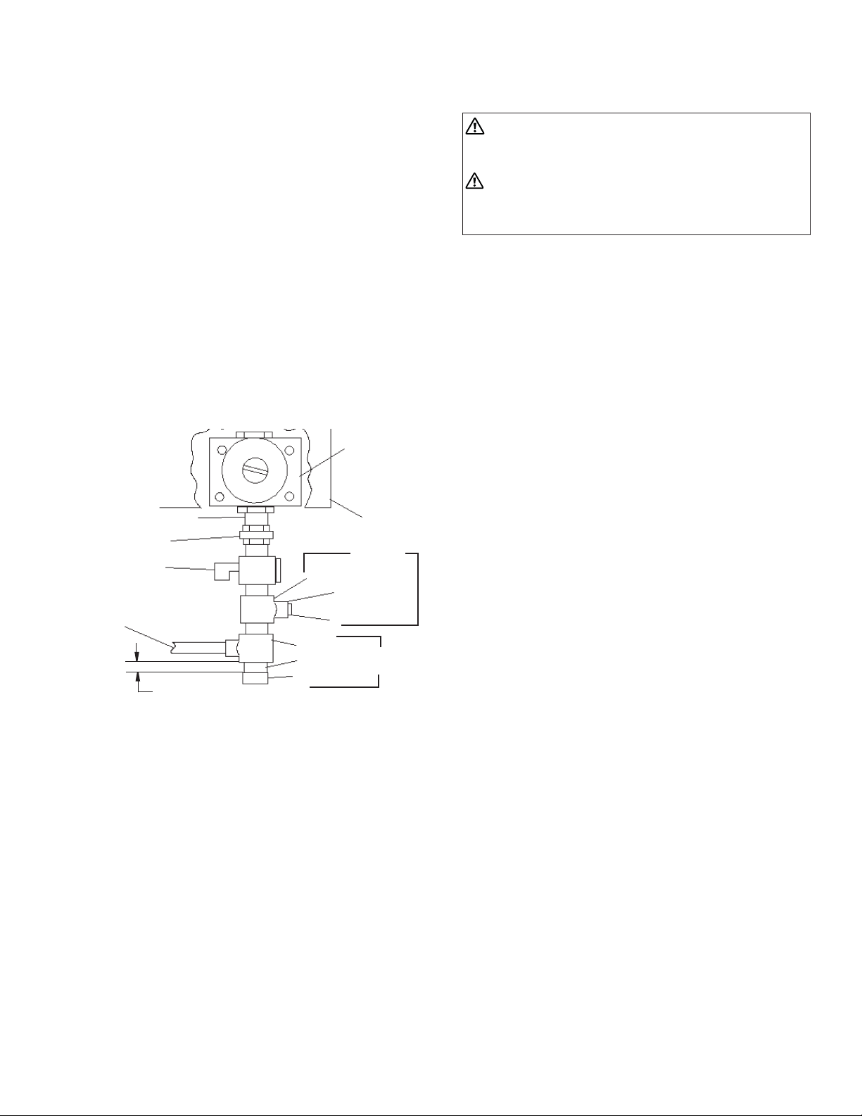
Installation must include an equipment shutoff valve,
union and plugged 1/8” NPT tap. Locate NPT tap within
reach of test gauge hookup. NPT tap must be upstream
from heater (see fi gure 12).
Figure 12
*A CSA/AGA certifi ed equipment shutoff valve with
1/8” NPT tap is an acceptable alternative to test gauge
connection. Purchase the CSA/AGA certifi ed equipment
shutoff valve from your dealer.
IMPORTANT: Install an equipment shutoff valve in an
accessible location. The equipment shutoff valve is for
turning on or shutting off the gas to the appliance.
Apply pipe joint sealant lightly to male threads. This will
prevent excess sealant from going into pipe. Excess
sealant in pipe could result in clogged heater fuel train.
CAUTION: Use pipe joint sealant that is resistant to
LP-Gas.
Install sediment trap in supply line as shown in fi gure
12. Locate sediment trap where it is within reach
for cleaning. A sediment trap traps moisture and
contaminants. This keeps them from going into heater.
If sediment trap is not installed or is installed improperly,
heater may not run correctly.
Pressure
Regulator
Heater
Cabinet
Ground Joint Union
Equipment
Shutoff Valve
From regulated LP tank
(11” W.C. to 14” W.C.
Pressure)
Tee Joint
1/8” NPT Plug Tap
Cap
Pipe Nipple
Tee Joint
3/8” NPT Pipe Nipple
Sediment
Trap
Test Gauge
Connection
Reducer Bushing
to 1/8” NPT
3” Minimum
IMPORTANT: Hold pressure regulator with wrench
when connecting it to gas piping and/or fi ttings.
CHECKING GAS CONNECTIONS
WARNING: Test all gas piping and connections for
leaks after installing or servicing. Correct all leaks
at once.
WARNING: Never use an open fl ame to check for
a gas leak. Apply a mixture of liquid soap and water
to all joints. Bubbles forming show a leak. Correct
all leaks at once.
PRESSURE TESTING GAS SUPPLY PIPING
SYSTEM
Test pressure in Excess of ½ psig (3.5kPa)
1. Disconnect appliance with its appliance main
gas valve (control valve) and equipment shutoff
valve from gas supply piping system. Pressures
in excess of ½ psig will damage heater
regulator.
2. Cap off open end of gas pipe where equipment
shutoff valve was connected.
3. Pressurize supply piping system by either using
compressed air or opening main gas valve on
or near gas meter.
4. Check all connections and joints in gas supply
piping system. Apply mixture of liquid soap and
water to gas joints. Bubbles forming show a
leak.
5. Correct all leaks at once.
6. Depressurize and relieve pressure in supply
piping system.
7. Reconnect heater and equipment shutoff valve
to gas supply.
8. Reconnected fi ttings must be checked for leaks
in next section.
Test Pressure Equal To or Less Than ½ psig (3.5 kPa)
1. Close equipment shutoff valve (see fi gure 13).
2. Pressurize supply piping system by either using
compressed air or opening main gas valve on
or near gas meter.
3. Check all joints from the gas meter to
equipment shutoff valve (see fi gure 14). Apply
mixture of liquid soap and water to gas joints.
Bubbles forming show a leak.
4. Correct all leaks at once.
5. Depressurize and relieve pressure from supply
piping system.
Loading ...
Loading ...
Loading ...