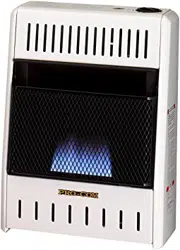
VENT-FREE NATURAL GAS
SPACE HEATER
OWNER’S OPERATION AND
INSTALLATION MANUAL
BLUE FLAME MODELS
MN060HBA, MN100HBA
MN100TBA
Questions, problems, missing parts? Before returning to your retailer, call
our customer service department at 1-866-573-0674, 7:30 am - 4:15 pm CST,
Monday through Friday or email customerservice@usaprocom.com
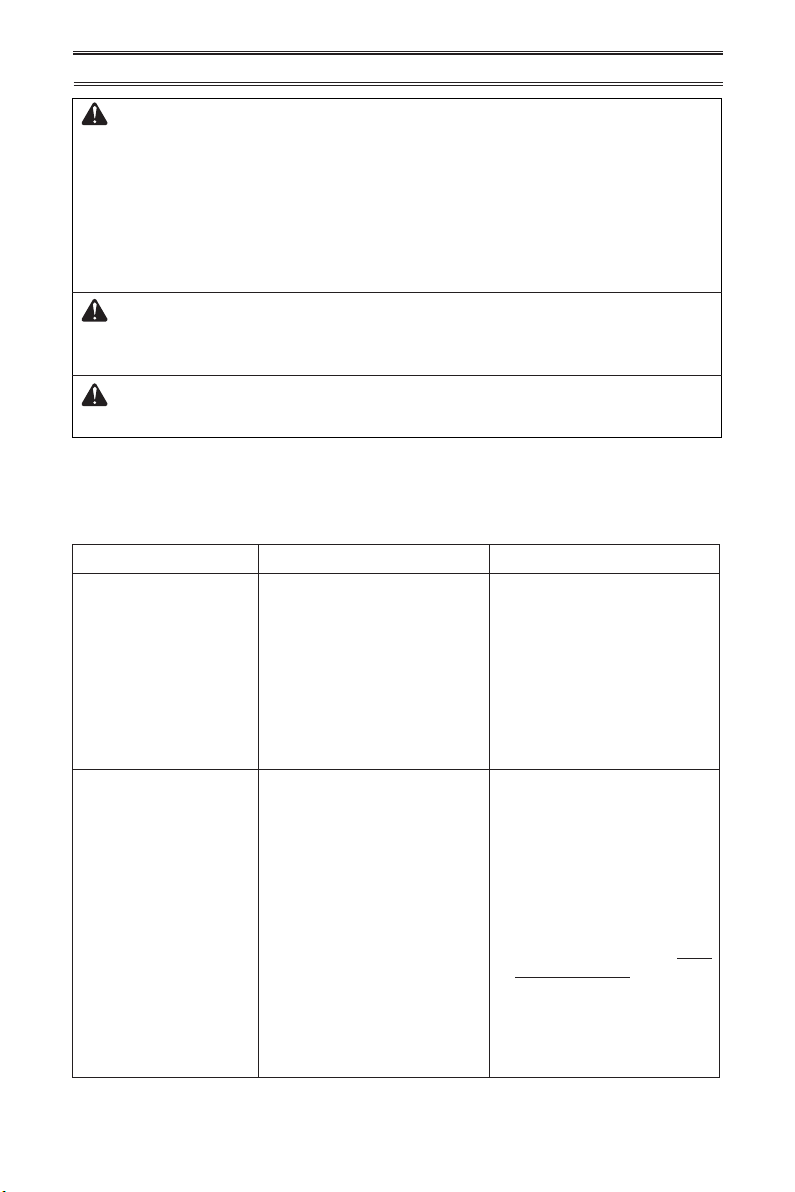
WARNING: If the information in this manual is not
followed exactly, a re or explosion may result causing
property damage, personal injury or loss of life.
— Do not store or use gasoline or other ammable va-
pors and liquids in the vicinity of this or any other
appliance.
— WHAT TO DO IF YOU SMELL GAS
• Do not try to light any appliance.
• Do not touch any electrical switch; do not use any
phone in your building.
•
Immediately call your gas supplier from a neighbor’s
phone. Follow the gas supplier’s instructions.
• If you cannot reach your gas supplier, call the re
department.
—
Installation and service must be performed by a quali-
ed installer, service agency or the gas supplier.
INSTALLER: Leave this manual with the appliance.
CONSUMER: Retain this manual for future reference.
www.usaprocom.com
200044-01B2
This is an unvented gas-red heater. It uses air (oxygen)
from the room in which it is installed. Provisions for ad-
equate combustion and ventilation air must be provided.
Refer to Air For Combustion and Ventilation section on
page 7 of this manual.
WARNING: Improper installation, adjustment, al-
teration, service or maintenance can cause injury or
property damage. Refer to this manual for correct in-
stallation and operational procedures. For assistance
or additional information consult a qualied installer,
service agency or the gas supplier.
This appliance may be installed in an aftermarket,* per-
manently located, manufactured (mobile) home, where
not prohibited by local codes.
This appliance is only for use with the type of gas indi-
cated on the rating plate. This appliance is not convert-
ible for use with other gases.
* Aftermarket: Completion of sale, not for purpose of resale, from the manufacturer.
SAVE THIS BOOK
TABLE OF CONTENTS
Safety ........................................................ 3
Specications ............................................ 4
Product Identication ................................. 5
Qualied Installing Agency ........................ 5
Product Features ....................................... 5
Local Codes............................................... 6
Unpacking.................................................. 6
Water Vapor: A By-Product Of
Unvented Room Heaters ..................... 6
Air For Combustion and Ventilation ........... 7
Installation ................................................. 9
Operation ................................................. 16
Inspecting Heater .................................... 19
Care And Maintenance ............................ 20
Troubleshooting ....................................... 21
Parts ........................................................ 24
Replacement Parts .................................. 30
Accessories ............................................. 30
Service Hints ........................................... 31
Technical Service..................................... 31
Warranty .................................................. 32
www.usaprocom.com
3200044-01B
SAFETY
IMPORTANT: Read this owner’s
manual carefully and completely
before trying to assemble, op-
erate, or service this heater.
Improper use of this heater can
cause serious injury or death
from burns, fire, explosion,
electrical shock and carbon
monoxide poisoning.
Only a qualied installer, service
agent, or local gas supplier may
install and service this product.
WARNING: Keep the appli-
ance area clear and free from
combustible materials, gasoline,
and other ammable vapors and
liquids.
This heater is equipped for natu-
ral gas. Field conversion is not
permitted.
This appliance is only for use
with the type of gas indicated on
the rating plate. This appliance
is not convertible for use with
other gases.
CARBON MONOXIDE POISONING: Early
signs of carbon monoxide poisoning resemble
the u, with headaches, dizziness or nausea.
If you have these signs, the heater may not be
working properly. Get fresh air at once! Have
heater serviced. Some people are more af-
fected by carbon monoxide than others. These
include pregnant women, people with heart or
lung disease or anemia, those under the inu-
ence of alcohol and those at high altitudes.
NATURAL GAS: Natural gas is odorless. An
odor-making agent is added to the gas. The
odor helps you detect a gas leak. However,
the odor added to the gas can fade. Gas may
be present even though no odor exists.
WARNING: Any change to
this heater or its controls can
be dangerous.
WARNING: Do not use any
accessories not approved for
use with this heater.
WARNING: Carefully super-
vise young children when they
are in the room with the heater.
WARNING: Make sure grill
guard is in place before running
heater.
WARNING: Due to high tem-
peratures, the appliance should
be located out of trafc and away
from furniture and draperies.
WARNING: Heater becomes
very hot when running. Keep
children and adults away from
hot surfaces to avoid burns or
clothing ignition. Heater will re-
main hot for a time after shutoff.
Allow surfaces to cool before
touching.
WARNING: Do not place
clothing or other flammable
material on or near the appli-
ance. Never place any objects
in the heater.

www.usaprocom.com
200044-01B4
1. Models MN100HBA and MN100TBA
shall not be installed in a bathroom.
2. This heater needs fresh air ventilation to
run properly. This heater has an Oxygen
Depletion Sensing (ODS) safety shutoff
system. The ODS shuts down the heater
if not enough fresh air is available. See
Air for Combustion and Ventilation, pages
7 and 8. If heater keeps shutting off, see
Troubleshooting, page 21.
3. Keep all air openings in front and bottom
of heater clear and free of debris. This will
ensure enough air for proper combustion.
4. If heater shuts off, do not relight until you
have provided fresh, outside air. If heater
keeps shutting off, have it serviced.
5. Do not run heater:
• Where ammable liquids or vapors are
SAFETY
used or stored.
• Under dusty conditions.
6. Before using furniture polish, wax, carpet
cleaner, or similar products, turn heater off.
If heated, the vapors from these products
may create a white powder residue within
burner box or on adjacent walls or furniture.
7. Do not use heater if any part has been
under water. Immediately call a qualied
service technician to inspect the room
heater and to replace any part of the
control system and any gas control which
has been under water.
8. Turn off heater and let cool before servic-
ing. Only a qualied service person should
service and repair heater.
9. Operating heater above elevations of
4,500 feet could cause pilot outage.
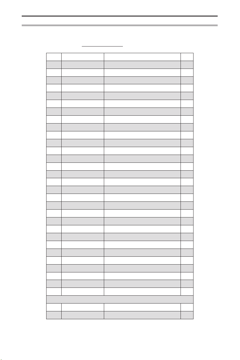
MODEL MN060HBA MN100HBA MN100TBA
Ignition Piezo Piezo Piezo
Gas Type Natural Gas Natural Gas Natural Gas
BTU (available) 6,000 6,000/10,000 10,000
Pressure Regulator Setting
3" W.C. 3" W.C. 3" W.C.
Inlet Gas Pressure*
(inches of water)
Maximum 10.5" Maximum 10.5" Maximum 10.5"
Minimum 4" Minimum 4" Minimum 4"
Heater Dim. (HxWxD)
19
1
/
8
" × 14
1
/
8
" × 6
3
/
8
" 19
1
/
8
" × 14
1
/
8
" × 6
3
/
8
" 19
1
/
8
" × 14
1
/
8
" × 6
3
/
8
"
Carton Dim. (HxWxD) 22" × 16
3
/
4
" × 8
1
/
8
" 22" × 16
3
/
4
" × 8
1
/
8
" 22" × 16
3
/
4
" × 8
1
/
8
"
Heater Weight 13 lbs 13 lbs 14 lbs
Shipping Weight 16 lbs 16 lbs 17 lbs
SPECIFICATIONS
Note: Dimensions listed are outer most points on the heater (includes control knobs and grill).
* For purposes of input adjustment.
www.usaprocom.com
5200044-01B
QUALIFIED INSTALLING AGENCY
Only a qualied agency should install and
replace gas piping, gas utilization equipment
or accessories, and repair and equipment ser-
vicing. The term “qualied agency” means any
individual, rm, corporation, or company that
either in person or through a representative
is engaged in and is responsible for:
a) Installing, testing, or replacing gas piping
or
b) Connecting, installing, testing, repairing,
or servicing equipment; that is experienced
in such work; that is familiar with all precau-
tions required; and that has complied with
all the requirement of the authority having
jurisdiction.
PRODUCT FEATURES
SAFETY PILOT
This heater has a pilot with an Oxygen Deple-
tion Sensing (ODS) safety shutoff system. The
ODS/pilot shuts off the heater if there is not
enough fresh air.
PIEZO IGNITION SYSTEM
This heater is equipped with a piezo ignitor.
this system requires no matches, batteries, or
other sources to light heater.
THERMOSTATIC CONTROL
(Thermostat Models Only)
These heaters have a control valve with a
thermostat sensing bulb. This results in the
greatest heater comfort and may result in
lower gas bills.
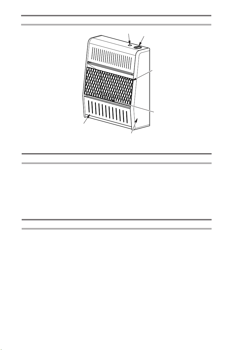
PRODUCT IDENTIFICATION
Figure 1 - Vent-Free Gas Heater
Control Knob
Ignitor Button
Front Panel
Grill
Burner
Heater Cabinet
www.usaprocom.com
200044-01B6
LOCAL CODES
Install and use heater with care. Follow all
local codes. In the absence of local codes,
use the latest edition of The National Fuel
Gas Code, ANSI Z223.1/NFPA 54*.
*Available from:
American National Standards Institute, Inc.
1430 Broadway
New York, NY 10018
National Fire Protection Association, Inc.
1 Batterymarch Park
Quincy, MA 02269-9101
State of Massachusetts: The installation
must be made by a licensed plumber or
gas tter in the Commonwealth of Mas-
sachusetts.
Sellers of unvented propane or natural
gas-red supplemental room heaters shall
provide to each purchaser a copy of 527
CMR 30 upon sale of the unit.
In the State of Massachusetts the gas
cock must be a T-handle type. The State
of Massachusetts requires that a exible
appliance connector cannot exceed three
feet in length.
UNPACKING
1. Remove heater from carton.
2. Remove all protective packaging applied
to heater for shipping
3. Check heater for any shipping damage. If
heater is damaged, promptly inform dealer
where you bought heater.
Water vapor is a by-product of gas combus-
tion. An unvented room heater produces ap-
proximately one (1) ounce (30 mL) of water for
every 1,000 BTUs (0.3 KWs) of gas input per
hour. Unvented room heaters are recommended
as supplemental heat (a room) rather than a
primary heat source (an entire house). In most
supplemental heat applications, the water vapor
does not create a problem. In most applications,
the water vapor enhances the low humidity
atmosphere experienced during cold weather.
The following steps will help ensure that water
vapor does not become a problem.
1. Be sure the heater is sized properly for the
application, including ample combustion
air and circulation air.
2. If high humidity is experienced, a dehu-
midier may be used to help lower the
water vapor content of the air.
3. Do not use an unvented room heater as
the primary heat source.
WATER VAPOR: A BY-PRODUCT OF
UNVENTED ROOM HEATERS
www.usaprocom.com
7200044-01B
AIR FOR COMBUSTION AND VENTILATION
WARNING: This heater shall
not be installed in a conned
space or unusually tight con-
struction unless provisions are
provided for adequate combus-
tion and ventilation air. Read the
following instructions to insure
proper fresh air for this and other
fuel-burning appliances in your
home.
Today’s homes are built more energy efcient
than ever. New materials, increased insulation
and new construction methods help reduce
heat loss in homes. Home owners weather
strip and caulk around windows and doors
to keep the cold air out and the warm air in.
During heating months, home owners want
their homes as airtight as possible.
While it is good to make your home energy
efcient, your home needs to breathe. Fresh
air must enter your home. All fuel-burning ap-
pliances need fresh air for proper combustion
and ventilation.
Exhaust fans, replaces, clothes dryers and
fuel burning appliances draw air from the
house to operate. You must provide adequate
fresh air for these appliances. This will insure
proper venting of vented fuel-burning appli-
ances.
WARNING: This heater shall
not be installed in a room or
space unless the required vol-
ume of indoor combustion air
is provided by the method de-
scribed in the National Fuel Gas
Code, ANSI Z223.1/NFPA 54, the
International Fuel Gas Code, or
applicable local codes.
WARNING: If the area in which
the heater may be operated does
not meet the required volume for
indoor combustion air, combus-
tion and ventilation air shall be
provided by one of the methods
described in the National Fuel
Gas Code, ANSI Z223.1/NFPA 54,
the International Fuel Gas Code,
or applicable local codes.
www.usaprocom.com
200044-01B8
AIR FOR COMBUSTION AND VENTILATION
Outlet
Air
Ventilated
Attic
Outlet
Air
Inlet
Air
Inlet Air
Ventilated
Crawl Space
To
Crawl
Space
To Attic
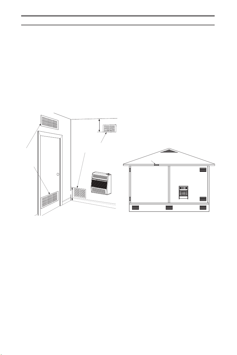
Figure 2 - Ventilation Air from Inside
Building
Figure 3 - Ventilation Air from Outdoors
Or
Remove
Door into
Adjoining
Room,
Option 3
Ventilation Grills
Into Adjoining Room,
Option 2
12"
12"
Ventilation
Grills into
Adjoining
Room,
Option 1
Ventilation Air From Inside Building
This fresh air would come from an adjoining
unconned space. When ventilating to an
adjoining unconned space, you must provide
two permanent openings: one within 12" of the
ceiling and one within 12" of the oor on the
wall connecting the two spaces (see options
1 and 2, Figure 2). You can also remove door
into adjoining room (see option 3, Figure 2).
Follow the National Fuel Gas Code, ANSI
Z223.1/NFPA 54, Air for Combustion and
Ventilation for required size of ventilation
grills or ducts.
VENTILATION AIR
Ventilation Air From Outdoors
Provide extra fresh air by using ventilation
grills or ducts. You must provide two perma-
nent openings: one within 12" of the ceiling
and one within 12" of the oor. Connect these
items directly to the outdoors or spaces open
to the outdoors. These spaces include attics
and crawl spaces. Follow the National Fuel
Gas Code, ANSI Z223.1/NFPA 54, Air for
Combustion and Ventilation for required size
of ventilation grills or ducts.
IMPORTANT: Do not provide openings
for inlet or outlet air into attic if attic has a
thermostat-controlled power vent. Heated air
entering the attic will activate the power vent.
Rework worksheet, adding the space of the
adjoining unconned space. The combined
spaces must have enough fresh air to supply
all appliances in both spaces.
www.usaprocom.com
9200044-01B
INSTALLATION
NOTICE: This heater is intended
for use as supplemental heat.
Use this heater along with your
primary heating system. Do not
install this heater as your pri-
mary heat source. If you have a
central heating system, you may
run system’s circulating blower
while using heater. This will help
circulate the heat throughout the
house. In the event of a power
outage, you can use this heater
as your primary heat source.
CAUTION: When installing
heater in a home garage
• heater pilot and burner must
be at least 18" above oor
• locate heater where moving
vehicle will not hit it
WARNING: A qualied ser-
vice person must install heater.
Follow all local codes.
WARNING: Never install the
heater
• Models MN100HBA or
MN100TBA in a bathroom
• in a recreational vehicle
• where curtains, furniture,
clothing, or other ammable
objects are less than 36" from
the front, top, or sides of the
heater
• in high trafc areas
• in windy or drafty areas
WARNING: MODEL
MN060HBA ONLY! When
installed in a bathroom, do not
use ammable products such
as aerosol hair spray or any
product that contains ammable
vapors. Keep towels and other
ammable materials away from
heater.
CAUTION: This heater cre-
ates warm air currents. These
currents move heat to wall sur-
faces next to heater. Installing
heater next to vinyl or cloth wall
coverings or operating heater
where impurities (such as to-
bacco smoke, aromatic candles,
cleaning uids, oil or kerosene
lamps, etc.) in the air exist, may
cause walls to discolor.
IMPORTANT: Vent-free heaters add moisture
to the air. Although this is benecial, installing
heater in rooms without enough ventilation air
may cause mildew to form too much moisture.
See Air for Combustion and Ventilation, pages
7 and 8.
CHECK GAS TYPE
Be sure your gas supply is right for your heat-
er. Otherwise, call dealer where you bought
the heater for proper type heater.
www.usaprocom.com
200044-01B10
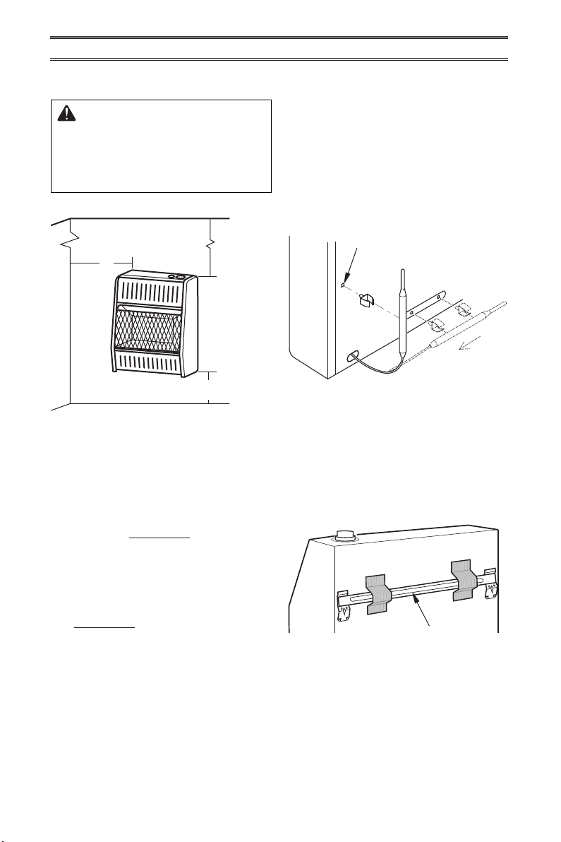
Figure 4 - Mounting Clearances as
Viewed From Front of Heater
INSTALLATION
FASTENING HEATER TO WALL
Mounting Bracket
The mounting bracket is located on back panel
of heater (see Figure 6). It has been taped
there for shipping. Remove mounting bracket
from back panel.
Figure 6 - Mounting Bracket Location
Figure 5 - Moving Thermostat Sensing
Bulb
Mounting Bracket
Pull
Out
Hole for Installing Clip
CEILING
36"
Minimum
6"
Minimum
From
Sides of
Heater
Left
Side
Right
Side
2" Minimum to Top Surface of Carpeting,
Tile or Other Combustible Material
FLOOR
LOCATING HEATER
This heater is designed to be mounted on a
wall. You can locate heater on the oor, away
from a wall. An optional oor mounting stand
is needed. See Accessories, page 30.
For convenience and efciency, install heater:
1. Where there is easy access for operation,
inspection, and service.
2. In the coldest part of room.
An optional fan kit is available from your dealer
See Accessories, page 30. If planning to use
fan, locate heater near an electrical outlet.
CLEARANCES TO
COMBUSTIBLES
WARNING: Maintain the
minimum clearances shown in
Figure 4. If you can, provide
greater clearances from oor,
ceiling, and joining wall.
INSTALLING THERMOSTAT
SENSING BULB (OPTIONAL)
1. Pull out the sensing bulb from the two clips
located in the shipping position according
to the direction as shown by the arrow.
There is no need to take out the two bulb
clips.
2. Take out the bulb clip from the hardware
package and insert it into the square hole.
Insert the sensing bulb into the bulb clip
(see Figure 5).
www.usaprocom.com
11200044-01B
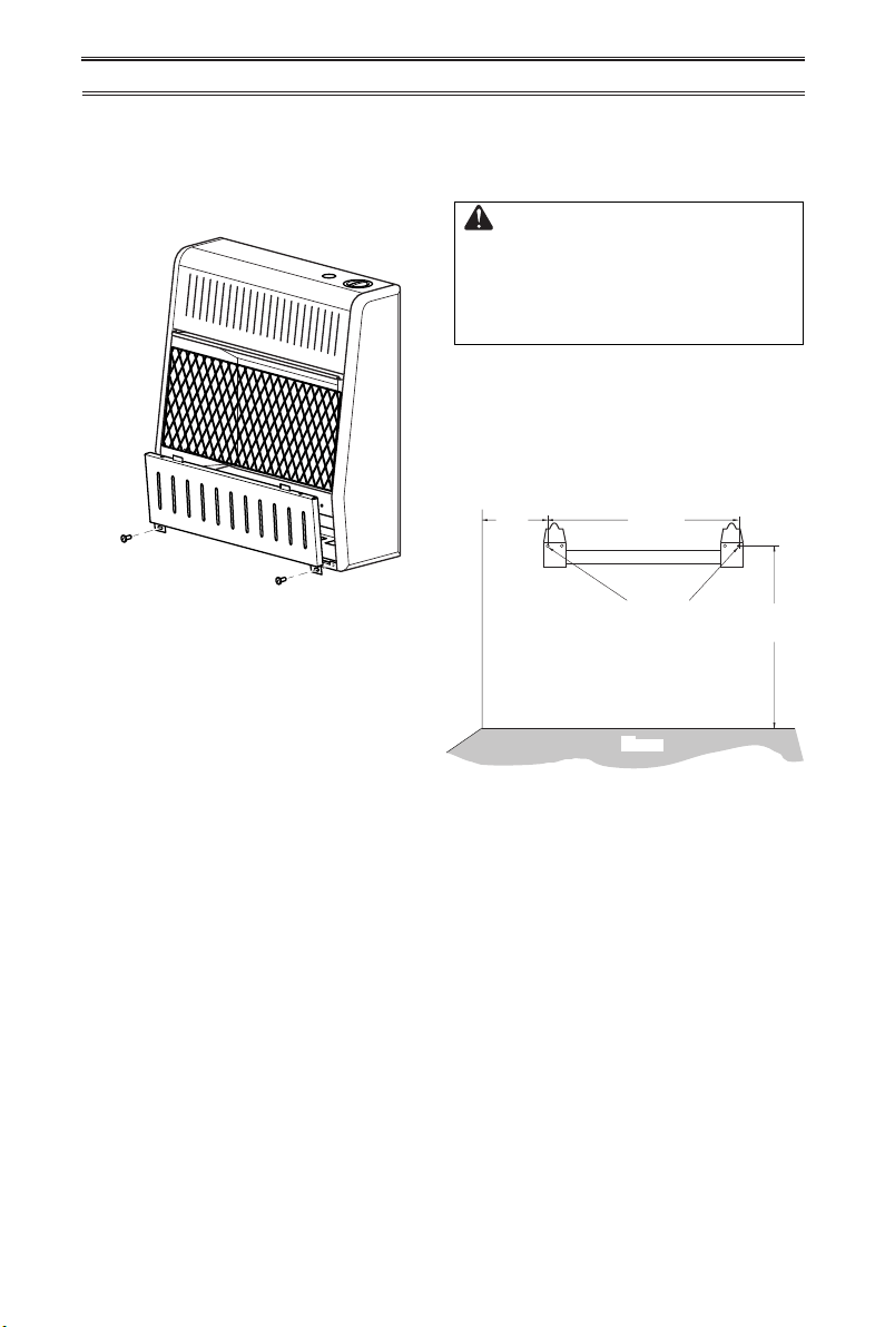
Removing Front Panel of Heater
1. Remove two screws near bottom corners
of lower front panel.
2. Pull bottom of lower front panel forward,
then down (see Figure 7).
Figure 7 - Removing Front Panel Of
Heater
Figure 8 - Mounting Bracket Clearances
INSTALLATION
Methods For Attaching Mounting
Bracket To Wall
Use only the last hole on each end of mount-
ing bracket to attach bracket to wall. Attach
mounting bracket to a wall only in one of two
ways:
1. Attaching to wall stud: This method pro-
vides the strongest hold. Insert mounting
screws through mounting bracket and into
wall studs.
2. Attaching to wall anchor: This method
allows you to attach mounting bracket to
hollow walls (wall areas between studs)
or to solid walls (concrete or masonry).
Decide which method better suits your needs.
Either method will provide a secure hold for
the mounting bracket.
12
1
/8"
14
1
/2"
Min.
6
3
/4"
Min.
Adjoining Wall
Only Insert Mounting
Screws Through Last
Hole On Each End
Floor
Marking Screw Locations
1. Tape mounting bracket to wall where
heater will be located. Make sure mount-
ing bracket is level.
WARNING: Maintain mini-
mum clearances shown in Figure
4, page 10. If you can, provide
greater clearances from oor
and joining wall.
2. Mark screw locations on wall (see Figure
8). Note: Mark only last hole on each end
of mounting bracket. Insert mounting
screws through these holes only.
3. Remove tape and mounting bracket from
wall.
Attaching Mounting Bracket To Wall
Note: Wall anchors, mounting screws, and
spacers are in hardware package. The hard-
ware package is provided with heater.
Attaching to Wall Stud Method
For attaching mounting bracket to wall studs:
1. Drill holes at marked locations using 9/64"
drill bit.
2. Place mounting bracket onto wall. Line
up last hole on each end of bracket with
holes drilled in wall.
3. Insert mounting screws through bracket
and into wall studs.
4. Tighten screws until mounting bracket is
rmly fastened to wall studs.
www.usaprocom.com
200044-01B12
Placing Heater On Mounting
Bracket
1. Locate two horizontal slots on back panel
of heater (see Figure 11).
2. Place heater onto mounting bracket. Slide
horizontal slots onto stand-out tabs on
mounting bracket.
INSTALLATION
Figure 11 - Mounting Heater Onto
Mounting Bracket
Mounting
Bracket
(attached
to wall)
Horizontal Slots
Stand-Out Tab
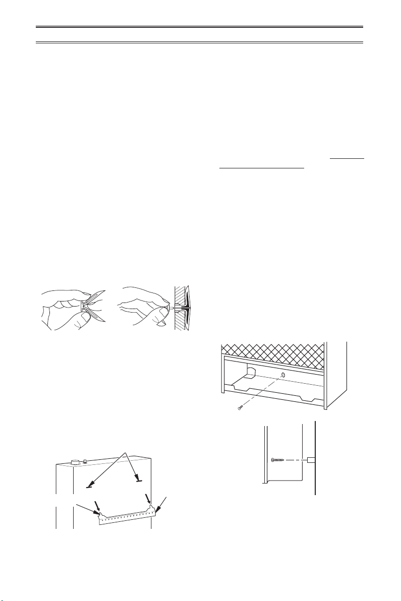
Installing Bottom Mounting Bracket
1. Install bottom bracket to heater bottom
with two screws. It may be more conve-
nient to remove heater from wall bracket
to attach.
2. Place heater on wall mounting bracket.
3. Mark screw locations on wall.
4. Remove heater from mounting bracket.
5.
If installing bottom mounting screws into
hollow or solid wall, install wall anchors.
Follow steps 1 through 4 under Attaching
To Wall Anchor Method. If installing bot-
tom mounting screw into wall stud, drill
holes at marked locations using 9/64"
drill bit.
6. Replace heater onto mounting bracket.
7. Place spacers between bottom mounting
holes and wall anchor or drilled hole.
8. Hold spacer in place with one hand. With
other hand, insert mounting screw though
bottom mounting hole and spacer. Place
tip of screw in opening of wall anchor or
drilled hole.
9. Tighten both screws until heater is rmly
secured to wall. Do not over tighten.
Note: Do not replace front panel at this time.
Replace front panel after making gas connec-
tions and checking for leaks.
Figure 12 - Installing Bottom Mounting
Screws
Side View
Front View
Figure 9 - Folding
Anchor
Figure 10 - Popping
Open Anchor Wings
For Thin Walls
Attaching to Wall Anchor Method
For attaching mounting bracket to hollow
walls (wall areas between studs) or solid walls
(concrete or masonry):
1. Drill holes at marked locations using
5/16" drill bit. For solid walls (concrete or
masonry), drill at least 1" deep.
2. Fold wall anchor as shown in Figure 9.
3. Insert wall anchor (wings rst) into hole.
Tap anchor ush to wall.
4. For thin walls (1/2" or less), insert red key
into wall anchor. Push red key to “pop”
open anchor wings (see Figure 10).
IMPORTANT: Do not hammer anchor key! For
thick walls (over 1/2" thick) or solid walls, do
not pop open wings.
5. Place mounting bracket onto wall. Line up
last hole on each end of bracket with wall
anchors.
6. Insert mounting screws through bracket
and into wall anchors.
7. Tighten screws until mounting bracket is
rmly fastened to wall.
www.usaprocom.com
13200044-01B
INSTALLATION
CONNECTING TO GAS SUPPLY
WARNING: A qualied ser-
vice technician must connect
heater to gas supply. Follow all
local codes.
WARNING: This appliance
requires a 3/8" NPT (National
Pipe Thread) inlet connection to
the pressure regulator.
WARNING: Never connect
heater to private (non-utility)
gas wells. This gas is commonly
known as wellhead gas.
WARNING: Do not over-
tighten gas connections.
CAUTION: Use only new,
black iron or steel pipe. Inter-
nally tinned copper tubing may
be used in certain areas. Check
your local codes. Use pipe of
1/2" diameter or greater to allow
proper gas volume to heater. If
pipe is too small, undue loss of
pressure will occur.
CAUTION: Check your gas
line pressure before connect-
ing heater to gas line. Gas line
pressure must be no greater than
10.5" of water. If gas line pres-
sure is higher, heater regulator
damage could occur.
CAUTION: Avoid damage to
regulator. Hold gas regulator
with wrench when connecting
into gas piping and/or ttings.
CAUTION: Use pipe joint
sealant that is resistant to natu-
ral gas.
Before installing heater, make sure you have
the items listed below:
• external regulator for propane/LP unit only
(supplied by installer)
• piping (check local codes)
• sealant (resistant to natural gas and pro-
pane/LP gas)
• equipment shutoff valve*
• test gauge connection*
• sediment trap
• tee joint
• pipe wrench
• exible gas hose (check local codes)
* A CSA design-certied equipment shutoff
valve with 1/8" NPT tap is an acceptable al-
ternative to test gauge connection. Purchase
the optional CSA design certied equipment
shutoff valve from your dealer.
www.usaprocom.com
200044-01B14
INSTALLATION
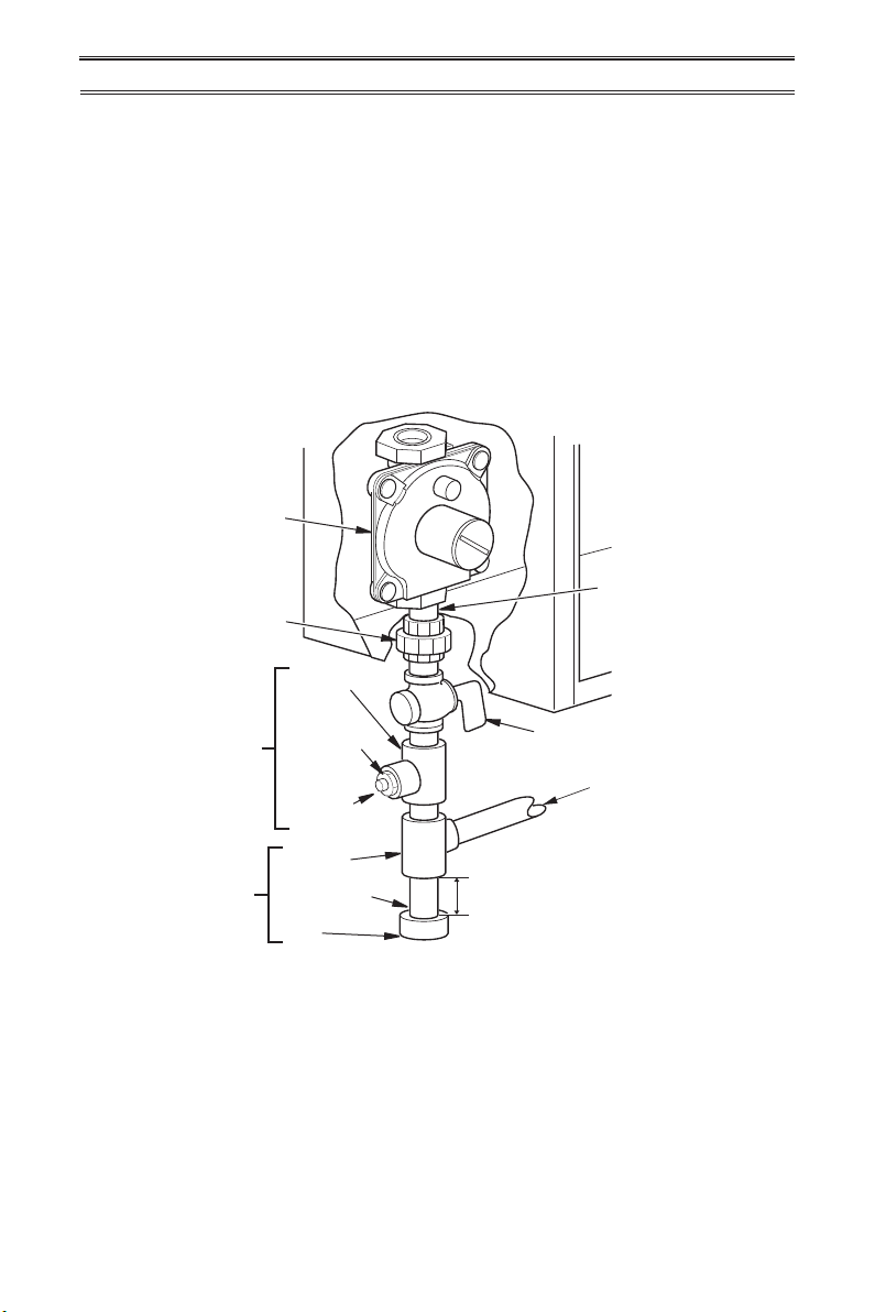
Figure 13 - Gas Connection
* Purchase the optional CSA design-certied equipment shutoff
valve from your dealer.
Equipment
Shutoff Valve
Ground
Joint
Union
Pressure
Regulator
3/8" NPT
Pipe Nipple
Tee Joint
Reducer
Bushing to
1/8" NPT
1/8" NPT
Plug Tap
Test Gauge
Connection*
Sediment
Trap
Tee Joint
Pipe Nipple
Gap
3" Minimum
From Gas Meter
(4" W.C. to
10.5" W.C.
Pressure)
Typical Inlet Pipe Diameters
Models up to 20,000 BTU/hr use 3/8" black
iron pipe or greater. Models 25,000 BTU/hr
and higher use 1/2" black iron pipe or greater.
Installation must include an equipment shutoff
valve, union, and plugged 1/8" NPT tap. Lo-
cate NPT tap within reach for test gauge hook
up. NPT tap must be upstream from heater
(see Figure 13.
IMPORTANT: Install an equipment shutoff
valve in an accessible location. The equip-
ment shutoff valve is for turning on or shutting
off the gas to the appliance.
Apply pipe joint sealant lightly to male threads.
This will prevent excess sealant from going
into pipe. Excess sealant in pipe could result
in clogged heater valves.
Install sediment trap in supply line as shown
in Figure 13. Place sediment trap where it is
within reach for cleaning. Place sediment trap
where trapped matter is not likely to freeze.
A sediment trap traps moisture and contami-
nants. This keeps them from going into heater
controls. If sediment trap is not installed or is
installed wrong, heater may not run properly.
www.usaprocom.com
15200044-01B
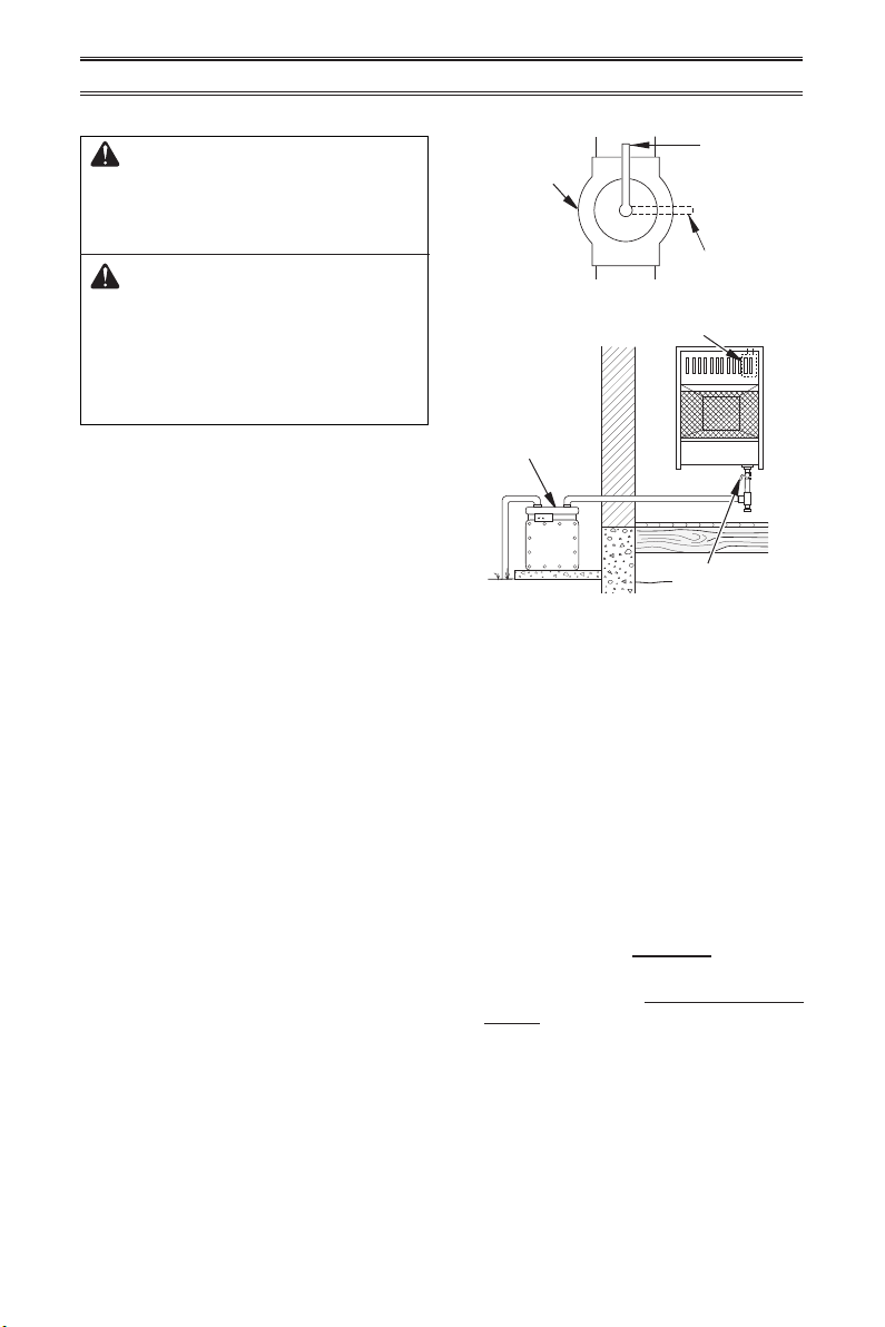
INSTALLATION
Figure 14 - Equipment Shutoff Valve
Open
Closed
Equipment
Shutoff Valve
Figure 15 - Natural Gas Supply
Gas Meter
Gas Valve
Equipment
Shutoff Valve
CHECKING GAS CONNECTIONS
WARNING: Test all gas piping
and connections for leaks after
installing or servicing. Correct
all leaks at once.
WARNING: Never use an
open ame to check for a leak.
Apply a mixture of liquid soap
and water to all joints. If bubbles
form, there is a leak. Correct all
leaks at once.
PRESSURE TESTING GAS SUPPLY
PIPING SYSTEM
Test Pressures In Excess Of 1/2 PSIG
(3.5 kPa)
1. Disconnect heater with its appliance main
gas valve (control valve) and equipment
shutoff valve from gas supply piping sys-
tem. Pressures in excess of 1/2 PSIG will
damage heater regulator.
2. Cap off open end of gas pipe where equip-
ment shutoff valve was connected.
3. Pressurize supply piping system by either
opening propane/LP supply tank valve
for propane/LP gas or opening main gas
valve located on or near gas meter for
natural gas or using compressed air.
4. Check all joints of gas supply piping sys-
tem. Apply a noncorrosive leak detection
uid to all joints. If bubbles form, there may
be a leak.
5. Correct all leaks at once.
6. Reconnect heater and equipment shutoff
valve to gas supply. Check reconnected
ttings for leaks.
Test Pressures Equal To or Less Than
1/2 PSIG (3.5 kPa)
1. Close equipment shutoff valve (see Fig-
ure 14).
2. Pressurize supply piping system by either
opening main gas valve located on or near
gas meter or using compressed air.
3. Check all joints from gas meter to equip-
ment shutoff valve (see Figure 15). Apply
a noncorrosive leak detection uid to all
joints. If bubbles form, there is a leak.
4. Correct all leaks at once.
PRESSURE TESTING HEATER GAS
CONNECTIONS
1. Open equipment shutoff valve (see Fig-
ure 14).
2. Open main gas valve located on or near
gas meter.
3. Make sure control knob of heater is in the
OFF position.
4. Check all joints from equipment shutoff
valve to control valve (see Figure 15).
Apply a noncorrosive leak detection uid
to all joints. Bubbles forming show a leak.
5. Correct all leaks at once.
6. Light heater (see Operation, page 16).
Check all other internal joints for leaks.
7. Turn off heater (see To Turn Off Gas Ap-
pliance, page 18).
8. Replace lower front panel.
www.usaprocom.com
200044-01B16
OFF
HIGH
LOW
PILOT/IGN
OFF
ON
PILOT/IGN
OPERATION
FOR YOUR SAFETY READ BEFORE LIGHTING
WARNING: If you do not fol-
low these instructions exactly, a
re or explosion may result caus-
ing property damage, personal
injury or loss of life.
A. This appliance has a pilot which must
be lighted by hand. When lighting the
pilot, follow these instructions exactly.
B. BEFORE LIGHTING smell all around the
appliance area for gas. Be sure to smell
next to the oor because some gas is
heavier than air and will settle on the oor.
WHAT TO DO IF YOU SMELL GAS
• Do not try to light any appliance.
• Do not touch any electric switch; do
not use any phone in your building.
• Immediately call your gas supplier
from a neighbor’s phone. Follow the
gas supplier’s instructions.
• If you cannot reach your gas supplier,
call the re department.
C. Use only your hand to push in or turn
the gas control knob. Never use tools.
If the knob will not push in or turn by
hand, don’t try to repair it, call a qualied
service technician. Force or attempted
repair may result in a re or explosion.
D. Do not use this appliance if any part
has been under water. Immediately call
a qualied service technician to inspect
the appliance and to replace any part of
the control system and any gas control
which has been under water.
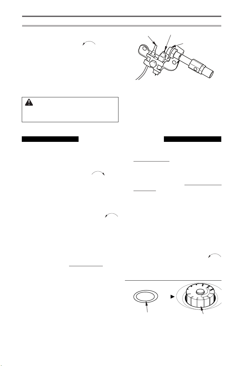
MANUAL CONTROL MODELS
LIGHTING INSTRUCTIONS
1. STOP! Read the safety information on
above.
2. Check that gas supply to heater is on.
3. Push in gas control knob slightly and turn
clockwise to the OFF position.
Note: Knob cannot be turned from PILOT to
OFF unless knob is pushed in slightly. Do
not force.
4. Wait ve (5) minutes to clear out any gas.
Then smell for gas, including near the
oor. If you smell gas, STOP! Follow "B"
in the safety information above. If you do
not smell gas, go to the next step.
5. Push in gas control knob slightly and turn
counterclockwise to "PILOT/IGN"
and press for ve (5) seconds
Note: The rst time that the heater is oper-
ated after connecting the gas supply, the
control knob should be pressed for about
thirty (30) seconds. This will allow air to
bleed from the gas system.
6. With control knob pressed in, push down
and release the ignitor button. This will
light pilot. If needed, keep pressing ignitor
button until pilot lights.
7. Keep control knob pressed in for 30
seconds after lighting pilot. After 30
seconds, release control knob. If control
knob does not pop up when released,
contact a qualied service technician or
gas supplier for repairs.
Note: If pilot goes out, repeat steps 3
through 7. This heater has a safety inter-
lock system. Wait one (1) minute before
lighting pilot again.
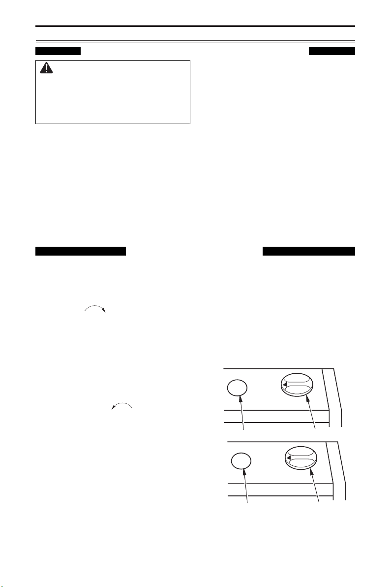
Figure 16 - Control Knob in the OFF
Position
Ignitor Button
Model MN060HBA
Model MN100HBA
Ignitor Button
Control Knob
Control Knob
www.usaprocom.com
17200044-01B
Figure 17 - Pilot
8. To select the desired heating level, partially
press down the control knob slightly and
turn counterclockwise . Release
downward pressure on the knob while
continuing to turn until the knob locks
at the desired setting. The main burner
should light. Set control knob to the de-
sired heating position.
Note: Both HIGH and LOW are locked
positions. You must press in the control
knob before turning it from these positions.
CAUTION: Do not try to ad-
just heating levels by using the
equipment shutoff valve.
OPERATION
Pilot Burner
Ignitor Electrode
Thermocouple
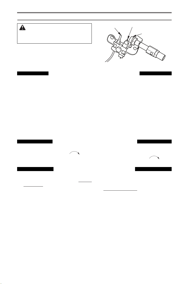
Figure 18 - Control Knob in the OFF
Position
1. STOP! Read the safety information on
page 16.
2. Make sure equipment shutoff valve is fully
open.
3. Turn control knob clockwise to the
OFF position.
4. Wait ve (5) minutes to clear out any air.
Then smell for gas, including near the
oor. If you smell gas, STOP! Follow "B"
in the safety information on page 16. If you
do not smell gas, go to the next step.
5. Turn control knob counterclockwise
to the PILOT position. Press in control
knob for ve (5) seconds (see Figure 18).
Note: The rst time that the heater is oper-
ated after connecting the gas supply,the
control knob should be pressed for about
thirty (30) seconds. This will allow air to
bleed from the gas system. If pilot does
not stay lit, refer to Troubleshooting, pages
21 though 23. Also contact a qualied
service technician or gas supplier for
repairs. Until repairs are made, light pilot
with match.
• If control knob does not pop up when
released, contact a qualified service
technician or gas supplier for repairs.
6. With control knob pressed in, push
down and release ignitor button. This
will light pilot. The pilot is attached to
the front of burner. The pilot can be
seen through the grill. If needed, keep
pressing ignitor button until pilot lights.
Note: If pilot does not stay lit, refer to
Troubleshooting, pages 22 though 24.
Also contact a qualied service technician
or gas supplier for repairs. Until repairs
are made, light pilot with match. To light
pilot with match, see Manual Lighting
Procedure, page 19.
7. Keep control knob pressed in for 30
seconds after lighting pilot. After 30
seconds, release control knob. If control
knob does not pop up when released,
contact a qualied service technician or
gas supplier for repairs.
Note: If pilot goes out, repeat steps 3
through 7. This heater has a safety inter-
lock system. Wait one (1) minute before
lighting pilot again.
8. Turn control knob counterclockwise
to desired heating level. The main burner
should light. Set control knob to any heat
level between HI and LO.
PILOT
LO
OFF
HI
Ignitor Button
Control Knob
THERMOSTAT MODELS
LIGHTING INSTRUCTIONS
www.usaprocom.com
200044-01B18
THERMOSTAT CONTROL OPERATION
ALL MODELS
TO TURN OFF GAS TO APPLIANCE
Shutting Off Heater
Turn control knob clockwise to the
OFF position.
Shutting Off Burner Only (pilot
stays lit )
Turn control knob clockwise to the
PILOT position.
OPERATION
MANUAL LIGHTING PROCEDURE
1. Remove lower front panel.
2. Follow steps 1 through 5 under Lighting
Instructions, page 16 or 17.
3. With control knob pressed in, strike match.
Hold match to pilot until pilot lights.
CAUTION: Do not try to ad-
just heating levels by using the
equipment shutoff valve.
Figure 19 - Pilot
Pilot Burner
Ignitor Electrode
Thermocouple
The thermostatic control used on these mod-
els differ from standard thermostats. Standard
thermostats simply turn the burner on and off.
The thermostat used on this heater senses
the room temperature. At times the room may
exceed the set temperature. If so, the burner
will shut off. The burner will cycle back on
when room temperature drops below the set
temperature. The control knob can be set to
any comfort level between HI and LO.
Note: The thermostat sensing bulb measures
the temperature of air near the heater cabinet.
This may not always agree with room tem-
perature (depending on housing construction,
installation location, room size, open air tem-
peratures, etc.) Frequent use of your heater
will let you determine your own comfort levels.
4. Keep control knob pressed in for 30 sec-
onds after lighting pilot. After 30 seconds,
release control knob. Follow step 8 under
Lighting Instructions, page 17.
5. Replace lower front panel.
www.usaprocom.com
19200044-01B
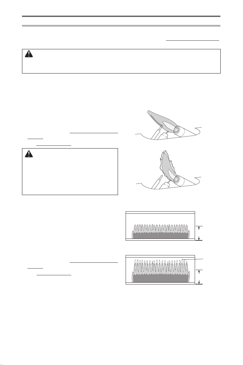
Figure 20 shows a correct pilot ame pattern.
Figure 21 shows an incorrect pilot ame pat-
tern. The incorrect pilot ame is not touching
the thermocouple. This will cause the ther-
mocouple to cool, which shuts the heater off.
If pilot ame pattern is incorrect, as shown
in Figure 21
• turn heater off (see To Turn Off Gas to Ap-
pliance, page 18)
• see Troubleshooting pages 21 through 23.
WARNING: If yellow tipping
occurs, your heater could pro-
duce increased levels of carbon
monoxide. If the burner ame
pattern shows yellow tipping,
follow instructions below.
Figure 20 - Correct Pilot Flame Pattern
Figure 21 - Incorrect Pilot Flame Pattern
IMPORTANT: Owner’s should check pilot ame pattern and burner ame pattern often.
Incorrect ame patterns indicate the need for cleaning (see Care and Maintenance,
page 20) or service.
WARNING: Only a qualied service person should service and
repair heater. This includes maintenance requiring replacement or
alteration of components.
PILOT FLAME PATTERN
Notice: Do not mistake orange ames with
yellow tipping. Dirt or other ne particles enter
the heater and burn causing brief patches of
orange ame.
BURNER FLAME PATTERN
Figure 22 shows a correct burner ame pat-
tern. Figure 23 shows an incorrect burner
ame pattern. The incorrect burner ame
pattern shows yellow tipping of the ame. It
also shows the ame higher than 1/2 the heat
shield height.
If burner ame pattern is incorrect, as shown
in Figure 23
• turn heater off (see To Turn Off Gas to Ap-
pliance, page 18)
• see Troubleshooting pages 21 through 23.
Figure 22 - Correct Burner Flame Pattern
Figure 23 - Incorrect Burner Flame
Pattern
INSPECTING HEATER
1/2 Glass
Height
1/2 Glass
Height
Yellow
Tipping
1/2 Glass
Height
1/2 Glass
Height
Yellow
Tipping
www.usaprocom.com
200044-01B20
CARE AND MAINTENANCE
WARNING: Turn off heater and let cool before servicing.
CAUTION: You must keep control areas, burner, and circulating
air passageways of heater clean. Inspect these areas of heater before
each use. Have heater inspected yearly by a qualied service techni-
cian. Heater may need more frequent cleaning due to excessive lint
from carpeting, bedding material, pet hair, etc.
WARNING: Failure to keep the primary air opening(s) of the
burner(s) clean may result in sooting and property damage.
The primary air inlet hole allows the proper
amount of air to mix with the gas. This pro-
vides a clean burning ame. Keep this hole
clear of dust, dirt and lint. Clean this air inlet
hole prior to each heating season. A blocked
air hole will create soot. We recommend that
you clean the unit every three months during
operation and have heater inspected yearly
by a qualied service person.
We also recommend that you keep the burner
tube and pilot assembly clean and free of dust
and dirt. To clean these parts we recommend
using compressed air no greater than 30 PSl.
Your local computer store, hardware store,
or home center may carry compressed air in
a can. You can use a vacuum cleaner in the
blow position. If using compressed air in a
can, please follow the directions on the can.
If you don’t follow directions on the can, you
could damage the pilot assembly.
1. Shut off the unit, including the pilot. Allow
the unit to cool for at least thirty minutes.
2. Inspect burner and pilot for dust and dirt.
CABINET
Air Passageways
Use pressurized air to clean.
Exterior
Use a soft cloth dampened with a mild soap and water mixture. Wipe the cabinet to remove dust.
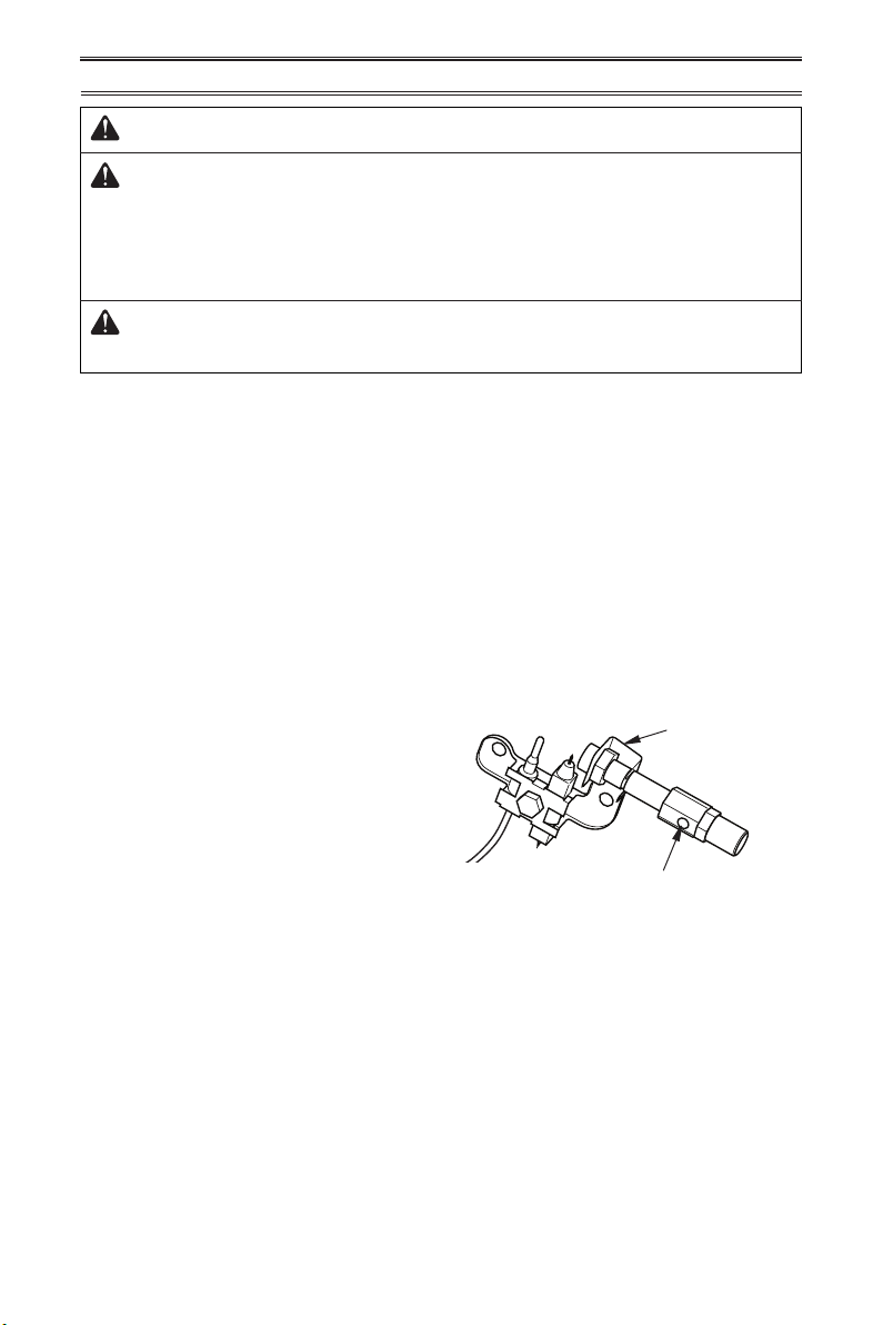
Figure 24 - Pilot Inlet Air Hole
Pilot Assembly
Pilot Air Inlet Hole
ODS/PILOT AND BURNER
Use a vacuum cleaner, pressurized air, or a small, soft bristled brush to clean.
BURNER PILOT AIR INLET
3. Blow air across the ports/slots and holes
in the burner.
4. Never insert objects into the pilot tube.
Clean the pilot assembly also. A yellow tip on
the pilot ame indicates dust and dirt in the
pilot assembly. There is a small pilot air inlet
about 2" from where the pilot ame comes out
of the pilot assembly (see Figure 24). With
the unit off, lightly blow air through the air
inlet. You may blow through a drinking straw
if compressed air is not available.
www.usaprocom.com
21200044-01B
TROUBLESHOOTING
WARNING: If you smell gas:
• Shut off gas supply.
• Do not try to light any appliance.
• Do not touch any electrical switch; do not use any phone in your
building.
• Immediately call your gas supplier from a neighbor’s phone. Fol-
low the gas supplier’s instructions.
• If you cannot reach your gas supplier, call the re department.
WARNING: Only a qualied service technician should service and
repair heater. Make sure that power is turned off before proceeding.
Turn off and let cool before servicing.
CAUTION: Never use a wire, needle, or similar object to clean
ODS/pilot. This can damage ODS/ pilot unit.
IMPORTANT: Operating heater where impurities in air exist may create odors. Cleaning sup-
plies, paint, paint remover, cigarette smoke, cements and glues, new carpet or textiles, etc.,
create fumes. These fumes may mix with combustion air and create odors.
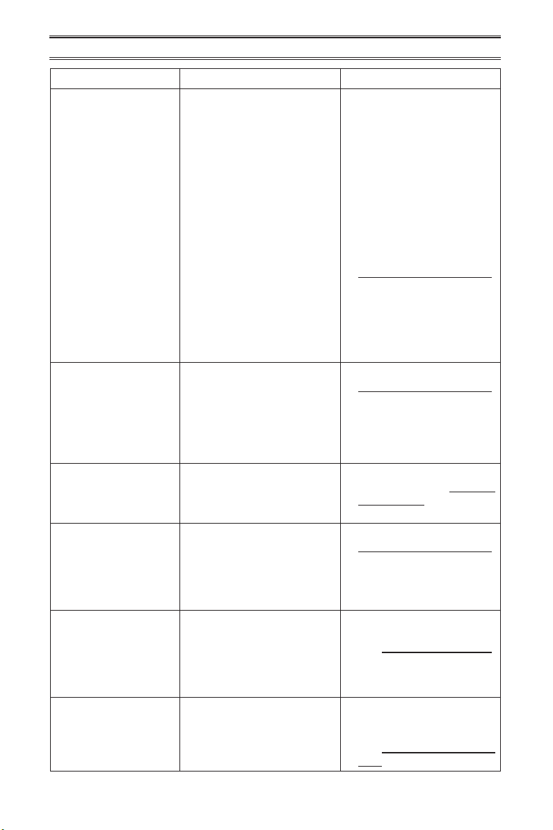
Note: All troubleshooting items are listed in order of operation.
Problem Possible Cause Corrective Action
When ignitor button is
pressed in, there is no
spark at ODS/pilot.
1. Ignitor electrode is posi-
tioned wrong. Ignitor elec-
trode is broken.
2. Ignitor electrode is not con-
nected to ignitor cable.
3. Ignitor cable is pinched or
wet.
4 Broken ignitor cable.
5. Bad piezo ignitor.
1. Replace pilot assembly.
2. Replace ignitor cable.
3. Free ignitor cable if pinched
by any metal or tubing. Keep
ignitor cable dry.
4. Replace ignitor cable.
5. Replace piezo ignitor.
When ignitor button is
pressed in there is a
spark at ODS/pilot but
no ignition.
1. Gas supply is turned off or
equipment shutoff valve is
closed.
2. Control knob not fully
pressed in while pressing
ignitor button.
3. Air in gas lines when in-
stalled.
4. ODS / pilot is clogged.
5. Incorrect inlet gas pressure
or inlet regulator is damaged.
6. Control knob not in PILOT
position.
1. Turn on gas supply or open
equipment shutoff valve.
2. Fully press in control knob
while pressing ignitor button.
3. Continue holding down con-
trol knob. Repeat igniting op-
eration until air is removed.
4.
Clean ODS/pilot (see Care
and Maintenance, page 20) or
replace ODS/pilot assembly.
5. Check inlet gas pressure or
replace inlet gas regulator.
6. Turn control knob to PILOT
position.
www.usaprocom.com
200044-01B22
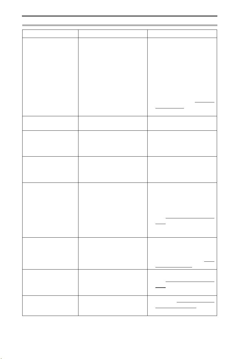
Problem Possible Cause Corrective Action
ODS/pilot lights but ame
goes out when control
knob is released.
1. Control knob is not fully
pressed in.
2. Control knob is not pressed
in long enough.
3. Equipment shutoff valve is
not fully open.
4. Thermocouple connection is
loose at control valve.
5. Pilot flame not touching
thermocouple, which allows
thermocouple to cool, caus-
ing pilot ame to go out. This
problem could be caused by
one or both of the following:
A) Low gas pressure
B) Dirty or partially clogged
ODS/pilot
6. Thermocouple damaged.
7. Control valve damaged.
1. Press in control knob fully.
2. After ODS/pilot lights, keep
control knob pressed in 30
seconds.
3. Fully open equipment shutoff
valve.
4. Hand tighten until snug, and
then tighten 1/4 turn more.
5. A) Contact local natural or
propane/LP gas company
B) Clean ODS/pilot (see
Care and Maintenance,
page 20) or replace ODS/
pilot assembly
6. Replace thermocouple
7. Replace control valve.
Burner(s) does not light
after ODS/pilot is lit.
1. Burner orice is clogged.
2. Burner orice diameter is too
small.
3. Inlet gas pressure is too low.
1. Clean burner orifice (see
Care and Maintenance,
page 20) or replace burner
orice.
2. Replace burner orice.
3. Contact local gas supplier.
Delayed ignition of
burner(s).
1. Manifold pressure is too low.
2. Burner orice is clogged.
1. Contact local gas supplier.
2. Clean burner (see Care and
Maintenance, page 20) or
replace burner orice.
Burner backring during
combustion.
1. Burner orice is clogged or
damaged.
2. Burner is damaged.
3. Gas regulator is damaged.
1. Clean burner orifice (see
Care and Maintenance,
page 20) or replace burner
orice.
2. Replace burner.
3. Replace gas regulator.
High yellow ame during
burner combustion.
1. Not enough air.
2. Gas regulator is defective.
3. Inlet gas pressure is too low.
1. Check burner for dirt and
debris. If found, clean burner
(see Care and Maintenance,
page 20).
2. Replace gas regulator.
3. Contact local gas supplier.
Gas odor during com-
bustion.
1. Foreign matter between
control valve and burner.
2. Gas leak. (See Warning
Statement at top of page 21).
1. Take apart gas tubing and
remove foreign matter.
2. Locate and correct all leaks
(see Checking Gas Connec-
tions, page 15).
TROUBLESHOOTING
www.usaprocom.com
23200044-01B
TROUBLESHOOTING
Problem Possible Cause Corrective Action
Heater produces a whis-
tling noise when burner
is lit.
1. Turning control knob to high
position when burner is cold.
2. Air in gas line.
3. Air passageways on heater
are blocked.
4. Dirty or partially clogged
burner orice.
1. Turn control knob to low
position and let warm up for
a minute.
2. Operate burner until air is
removed from line. Have gas
line checked by local gas
supplier.
3 Observe minimum installa-
tion clearances (Figure 4,
page 10).
4 Clean burner (see Care and
Maintenance, page 20) or
replace burner orice.
Slight smoke or odor
during initial operation.
1. Residues from manufactur-
ing process.
1. Problem will stop after a few
hours of operation.
Heater produces a click-
ing/ticking noise just after
burner is lit or shut off.
1. Metal is expanding while
heating or contracting while
cooling.
1. This is common with most
heaters. If noise is exces-
sive, contact qualied ser-
vice technician.
White powder residue
forming within burner
box or on adjacent walls
or furniture.
1. When heated, the vapors
from furniture polish, wax,
carpet cleaners, etc., turn
into white powder residue.
1. Turn heater off when using
furniture polish, wax, carpet
cleaner or similar products.
Heater produces un-
wanted odors.
1. Heater is burning vapors from
paint, hair spray, glues, etc.
See IMPORTANT statement,
page 21.
2. Gas leak. See Warning State-
ment at the top of page 21.
3. Low fuel supply (propane/LP
gas only).
1. Ventilate room. Stop using
odor causing products while
heater is running.
2. Locate and correct all leaks
(see Checking Gas Connec-
tions, page 15).
3. Rell supply tank (Propane/
LP models).
Heater shuts off in use
(ODS operates).
1. Not enough fresh air is avail-
able.
2. Low line pressure.
3. ODS/pilot is partially
clogged.
1. Open window and/or door for
ventilation.
2. Contact local gas supplier.
3. Clean ODS/pilot (see Care
and Maintenance, page 20).
Gas odor exists even
when control knob is in
OFF position.
1. Gas leak. See Warning
Statement at top of page 21.
2. Control valve is defective.
1. Locate and correct all leaks
(see Checking Gas Connec-
tions, page 15).
2. Replace control valve.
Moisture/condensation
noticed on windows.
1. Not enough combustion/
ventilation air.
1. Refer to Air for Combus-
tion and Ventilation require-
ments, page 7.
www.usaprocom.com
200044-01B24
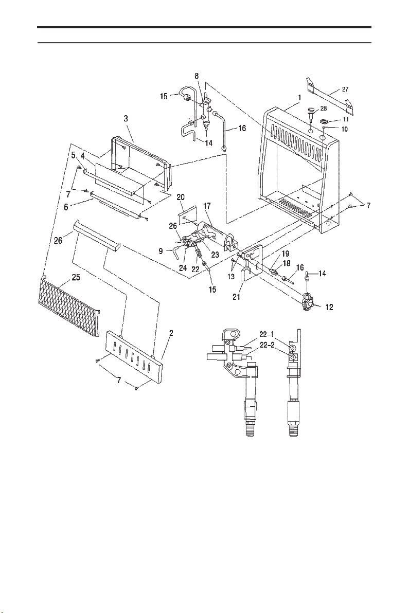
PARTS
MODEL MN060HBA
www.usaprocom.com
25200044-01B
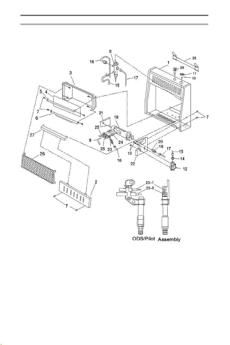
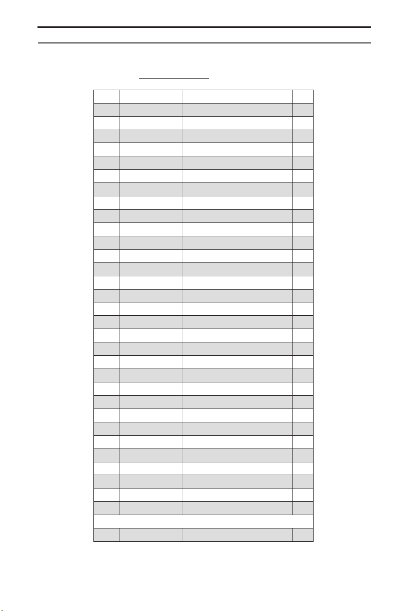
PARTS
MODEL MN060HBA
This list contains replaceable parts for your heater. When ordering replacement parts, follow
the instructions listed under Replacement Parts on page 30 of this manual.
ITEM PART # DESCRIPTION QTY
1 **MB10008 Cabinet Assembly 1
2 MB09003 Lower Front Panel 1
3 **MB11005 Reector Unit 1
4 ML086-03 Glass 1
5 ML087-03 Upper Glass Retainer 1
6 ML088-03 Lower Glass Retainer 1
7 ML069-02 Self Tapping Screw 12
8 NV2020-12 Control Valve 1
9 ML073-02 Ignitor Cable 1
10 ML029-01 Control Valve Fixed Nut 1
11 ML031-03 Control Knob 1
12 RV81FI-3 Pressure Regulator 1
13 ML079-01 Self Locking Screw 2
14 **ML119-01 Pressure Tap 1
15 **MB40033 Main Inlet Tube Assembly 1
16 **MB40045 ODS Line Assembly 1
17 **MB40043 Gas Outlet Tube Assembly 1
18 **NBB10-000M1 Burner 1
19 **ML101-02 Burner Connector 1
20 ML091-06 Injector 1
21 **ML103-02 Left Burner Support Bracket 1
22 **ML129-02 Regulator Mounting Bracket 1
23 ND1103x600 ODS/Pilot Assembly 1
23-1 ND0803-6 Thermocouple 1
23-2 ND0807 Ignitor Electrode 1
24 **ML105-01 ODS Deector 1
25 6170-5Z Nut 2
26 MB29003 Grill Guard 1
27 **ML084-03 Middle Panel 1
28 MB060-02 Mounting Bracket 1
29 ML083-03 Ignitor 1
PARTS AVAILABLE - NOT SHOWN
MB28001 Hardware Package 1
** Not a eld replaceable part.
www.usaprocom.com
200044-01B26
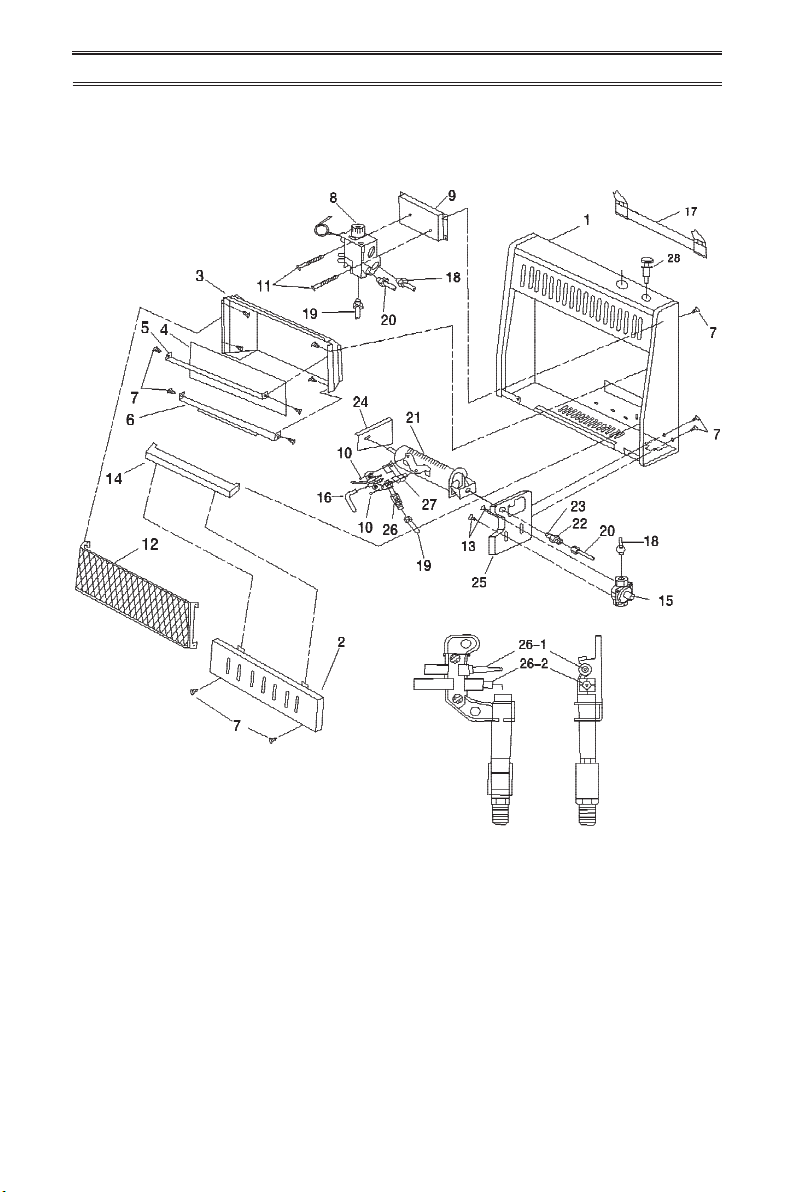
PARTS
MODEL MN100HBA
ODS/Pilot Assembly
www.usaprocom.com
27200044-01B
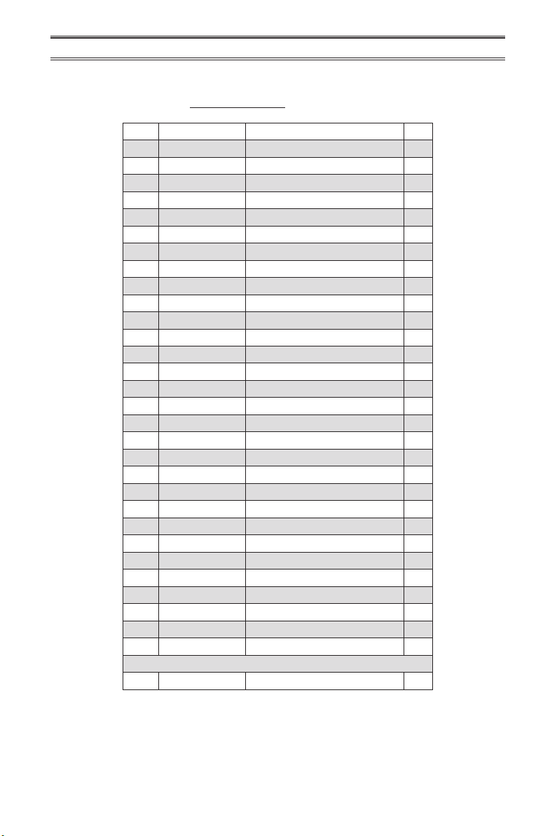
PARTS
MODEL MN100HBA
This list contains replaceable parts for your heater. When ordering replacement parts, follow
the instructions listed under Replacement Parts on page 30 of this manual.
ITEM PART # DESCRIPTION QTY
1 **MB10008 Cabinet Assembly 1
2 MB09003 Lower Front Panel 1
3 **MB11005 Reector Unit 1
4 ML086-03 Glass 1
5 ML087-03 Upper Glass Retainer 1
6 ML088-03 Lower Glass Retainer 1
7 ML069-02 Self Tapping Screw 12
8 NV2020-1213 Control Valve 1
9 ML073-02 Ignitor Cable 1
10 **ML029-01 Control Valve Fixed Nut 1
11 ML031-03 Control Knob 1
12 RV81FI-3 Pressure Regulator 1
13 ML079-01 Self Locking Screw 2
14 **MB40034A Main Inlet Tube Assembly 1
15 **MB40056 ODS Line Assembly 1
16 **MB40054 Gas Outlet Tube Assembly 1
17 **NBB10-000M1 Burner 1
18 **ML101-01 Burner Connector 1
19 ML091-05 Injector 1
20 **ML103-02 Left Burner Support Bracket 1
21 **ML129-02 Regulator Mounting Bracket 1
22 ND1103x600 ODS/Pilot 1
22-1 ND0803-6 Thermocouple 1
22-2 ND0807 Ignitor Electrode 1
23 **ML105-01 ODS Deector 1
24 6170-5Z Nut 2
25 MB29003 Grill Guard 1
26 **ML084-03 Middle Panel 1
27 MB060-02 Mounting Bracket 1
28 ML083-03 Ignitor 1
PARTS AVAILABLE - NOT SHOWN
MB28001 Hardware Package 1
** Not a eld replaceable part.
www.usaprocom.com
200044-01B28
PARTS
MODEL MN100TBA
ODS/Pilot Assembly
www.usaprocom.com
29200044-01B
PARTS
MODEL MN100TBA
This list contains replaceable parts for your heater. When ordering replacement parts, follow
the instructions listed under Replacement Parts on page 30 of this manual.
ITEM PART # DESCRIPTION QTY
1 **MB10007 Cabinet Assembly 1
2 MB09003 Lower Front Panel 1
3 **MB11005 Reector Unit 1
4 ML086-03 Glass 1
5 ML087-03 Upper Glass Retainer 1
6 ML088-03 Lower Glass Retainer 1
7 ML069-02 Self Tapping Screw 12
8 STL1001 Thermostat Valve Assembly 1
9 **ML111-02A Thermostat Valve Base/Bracket 1
10 6170-5Z Nut 2
11 845-4.8x60Z Screws 2
12 MB29003 Grill Guard 1
13 ML079-01 Self Locking Screw 2
14 **ML084-03 Middle Panel 1
15 RV81FI-3 Pressure Regulator 1
16 ML073-02 Ignitor Cable 1
17 MB060-02 Mounting Bracket 1
18 **MB40037 Main Inlet Tube Assembly 1
19 **MB40049 ODS Line Assembly 1
20 **MB40050 Burner Inlet Tube Assembly 1
21 **NBB10-000M1 Burner 1
22 **ML101-01 Burner Connector 1
23 ML091-05 Injector 1
24 **ML103-02 Left Burner Support Bracket 1
25 **ML129-02 Regulator Mounting Bracket 1
26 ND1103x800 ODS/Pilot 1
26-1 ND0803-8 Thermocouple 1
26-2 ND0807-B2 Ignitor Electrode 1
27 **ML105-01 ODS Deector 1
28 ML083-03 Ignitor 1
PARTS AVAILABLE - NOT SHOWN
MB28001 Hardware Package 1
ML065-01 Thermostat Sensing Bulb Clip 2
** Not a eld replaceable part.
www.usaprocom.com
200044-01B30
REPLACEMENT PARTS
PARTS UNDER WARRANTY
Contact authorized dealers of this product.
If they can’t supply original replacement
parts, call Customer Service toll free at
1-866-573-0674 for referral information.
When calling Customer Service or your dealer,
have ready:
• Your name
• Your address
• Model and serial number of your heater
• How heater was malfunctioning
• Type of gas used (Propane/LP or Natural
gas/NG)
• Purchase date
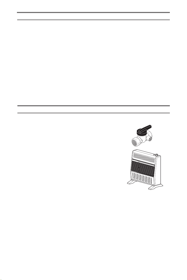
ACCESSORIES
Purchase these heater accessories from your local dealer. If they can not supply these acces-
sories, contact ProCom Heating, Inc. at 1-866-573-0674 for information.
EQUIPMENT SHUTOFF VALVE
For all models. Equipment shutoff valve with 1/8" NPT tap.
FLOOR MOUNTING STAND
PF09B For locating heater on the oor, away from a wall. Complete
installation instructions provided with oor mounting stand.
Usually, we will ask you to return the defective
part to the factory
PARTS NOT UNDER WARRANTY
Contact authorized dealers of this product.
If they can’t supply original replacement
part(s) call Customer Service toll free at
1-866-573-0674 for referral information.
When calling Customer Service have ready:
• Model number of your heater
• The replacement part number
Note: Use only original replacement parts. This will protect your warranty coverage for parts
replaced under warranty.

www.usaprocom.com
31200044-01B
SERVICE HINTS
TECHNICAL SERVICE
You may have further questions about installation, operation, or troubleshooting. If so, contact
ProCom Heating, Inc. at 1-866-573-0674.
When calling, please have your model and serial numbers of your heater ready.
When Gas Pressure Is Too Low
• pilot will not stay lit
• burners will have delayed ignition
• replace will not produce specied heat
• propane/LP gas supply might be low (pro-
pane/LP units only)
You may feel your gas pressure is too low. If
so, contact your local gas supplier.

200044-01
Rev. B
07/14
WARRANTY
KEEP THIS WARRANTY
Model _______________________________
Serial No. ____________________________
Date Purchased _______________________
Keep receipt for warranty verication.
REGISTER YOUR PRODUCT AT WWW.USAPROCOM.COM
IMPORTANT: We urge you to register your product within 10 days of date of installation, complete
with entire serial number which can be found on the rating plate. Please ll out the warranty infor-
mation above for your personal records. Retain this manual for future reference.
Always specify model and serial numbers when communicating with customer service.
We reserve the right to amend these specications at any time without notice. The only warranty applicable
is our standard written warranty. We make no other warranty, expressed or implied.
LIMITED WARRANTY
ProCom Heating, Inc. warrants this product to be free from defects in materials and components for ONE
(1) year from the date of rst purchase, provided that the product has been properly installed by a qualied
installer in accordance with all local codes and instructions furnished with the unit, operated and main-
tained in accordance with all applicable instructions. To make a claim under this warranty, the Bill of Sale
or cancelled check must be presented.
RESPONSIBILITY OF OWNER
This warranty is extended only to the original retail purchaser. This warranty covers the cost of part(s)
required to restore this heater to proper operating condition. Warranty part(s) MUST be obtained through
ProCom Heating, Inc. who will provide original factory replacement parts. Failure to use original factory
replacement parts voids this warranty.
IMPORTANT: The heater MUST be installed by a qualied installer in accordance with all local codes
and instructions furnished with the unit or the warranty is voided.
WHAT IS NOT COVERED
This warranty does not apply to parts that are not in original condition because of normal wear and tear or
parts that fail or become damaged as a result of misuse, accidents, lack of proper maintenance or defects
caused by improper installation. Travel, diagnostic cost, labor, transportation and any and all such other
costs related to repairing a defective heater will be the responsibility of the owner.
TO THE FULL EXTENT ALLOWED BY THE LAW OF THE JURISDICTION THAT GOVERNS THE SALE
OF THE PRODUCT, THIS EXPRESS WARRANTY EXCLUDES ANY AND ALL OTHER EXPRESSED
WARRANTIES AND LIMITS THE DURATION OF ANY AND ALL IMPLIED WARRANTIES. INCLUDING
WARRANTIES OF MERCHANTABILITY AND FITNESS FOR A PARTICULAR PURPOSE TO ONE (1)
YEAR ON ALL COMPONENTS FROM THE DATE OF FIRST PURCHASE. PROCOM HEATING, INC.'S
LIABILITY IS HEREBY LIMITED TO THE PURCHASE PRICE OF THE PRODUCT AND PROCOM HEAT-
ING, INC. SHALL NOT BE LIABLE FOR ANY OTHER DAMAGES WHATSOEVER INCLUDING INDIRECT.
INCIDENTAL OR CONSEQUENTIAL DAMAGES.
Some states do not allow a limitation on how long an implied warranty lasts or an exclusion or limitation of
accidental or consequential damages, the above limitation on implied warranties, or exclusion or limitation
on damages may not apply to you.
This warranty gives you specic legal right, and you may also have other rights that vary from state to state.
ProCom Heating, Inc.
Bowling Green, KY 42101
www.usaprocom.com
1-866-573-0674