Loading ...
Loading ...
Loading ...
Transporting Pole Saw
• A ways remove the battery pack from the _ _ I
handle (figure 7) and cover the chain with the I_O' _'_/_ I
scabbard (figure 8) when transporting the Pole _/_/,: _=_:_: ,_
Saw. See page 8 for additional information on I /_*: ,,_i_d
transporting the battery. I _'i,_I'_I
Joinincl Saw Head Module to Handle Module
WARNING: Sharp moving blade. To prevent accidental
operation, insure that battery is disconnected from the handle
and that the protective scabbard is in place on the chain before
performing the following operations. Failure to do this could
result in serious personal injury.
The three modules which make up the Pole Saw are keyed to insure
correct assembly. If a module does not smoothly attach to another do
not force fit.
Combining the handle module (A) to the saw head module (C)
creates a pole saw that is approximately 6 foot in length as shown in
figure 9.
To attach the handle module to the saw head module:
1. Align the groove on the outside of the coupling end of the handle
module (A) with the tongue on the inside of the coupling end of
the saw head module (C). See figure 10. Push the two sections
completely together.
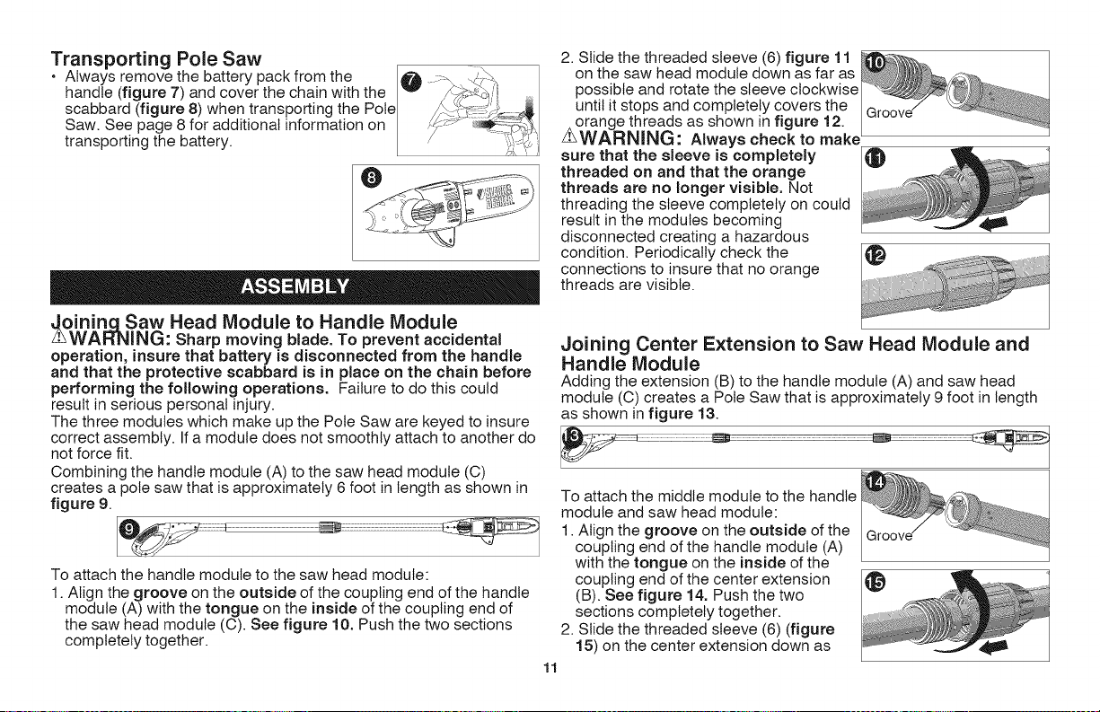
2. Slide the threaded sleeve (6) figure 11
on the saw head module down as far as
possible and rotate the sleeve clockwise
until it stops and completely covers the
Z orange threads as shown in figure 12.
WARNING: Always check to make _
sure that the sleeve is completely
threaded on and that the orange
threads are no longer visible. Not
threading the sleeve completely on could
result in the modules becoming
disconnected creating a hazardous
condition. Periodically check the
connections to insure that no orange
threads are visible.
Joining Center Extension to Saw Head Module and
Handle Module
Adding the extension (B) to the handle module (A) and saw head
module (C) creates a Pole Saw that is approximately 9 foot in length
as shown in figure 13.
To attach the middle module to the handle
module and saw head module:
1. Align the groove on the outside of the
coupling end of the handle module (A)
with the tongue on the inside of the
coupling end of the center extension
(B). See figure 14. Push the two
sections completely together.
2. Slide the threaded sleeve (6) (figure
15) on the center extension down as
11
Loading ...
Loading ...
Loading ...