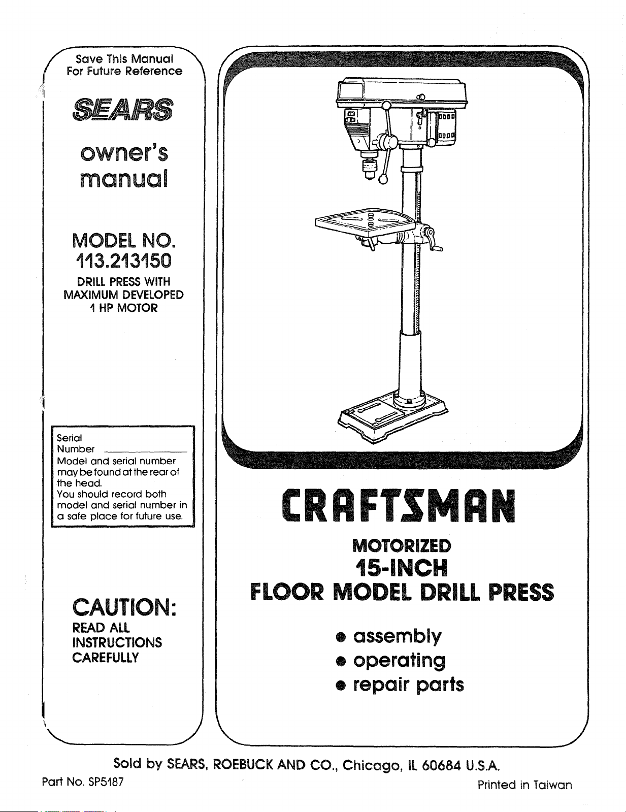
Save ThisManual \
For FutureReference
MODEL NO.
143,213150
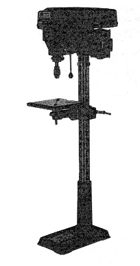
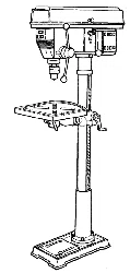
DRILL PRESS WITH
MAXIMUM DEVELOPED
I HP MOTOR
Serial
Number
Model and serial number
may be found at the rear of
the head.
You should record both
model and serial number in
a safe place for future use.
i
CAUTION:
READALL
INSTRUCTIONS
CAREFULLY
I
CRRFrSMRN
MOTORIZED
t5-|NCH
FLOOR MODEL DRILL PRESS
• assembly
• operating
• repair parts
Sold by SEARS, ROEBUCK AND CO., Chicago, IL 60684 U.S.A.
Part No. SP5187 Printed in Taiwan

FULL ONEYEAR WARRANTY ON CRAFTSMAN DRILL PRESS
If within one year from the date of purchase, this Craftsman Drill Press fails due to a defect
in material or workmanship, Sears will repair it, free of charge.
WARRANTY SERVICE IS AVAILABLE BY SIMPLY CONTACTING THE NEAREST SEARS SER-
VICE CENTER/DEPARTMENT THROUGHOUT THE UNITED STATES.
This warranty applies only while this product is used in the United States.
This warranty gives you specific legal rights, and you may also have other rights which
vary from state to state.
SEARS, ROEBUCK AND CO., Dept. 698/731A, Sears Tower, Chicago, IL 60684
GENERAL SAFETY iNSTRUCTiONS FOR POWER TOOLS
1. KNOW YOUR POWER TOOL
Read and understand the owner's manual and
labels affixed to the tool. Learn its application and
limitations as well as the specific potential hazards
peculiar to this tool.
2. GROUND ALL TOOLS
Thistoolis equipped with an approved 3-conductor
cord and a 3-prong grounding type plug to fit the
proper grounding type receptacle. The green con-
ductor in the cord is the grounding wire. Never
connect the green wire to a live terminal.
3. KEEP GUARDS IN PLACE
In working order, and in proper adjustment and
alignment.
4. REMOVE ADJUSTING KEYS AND WRENCHES
Form a habit of checking to see that keys and
adjusting wrenches are removed from toot before
turning it on
5. KEEP WORK AREA CLEAN
Clutteredareasand benchesinviteaccidents. Floor
must not be slipperydue to wax or sawdust.
6. AVOID DANGEROUS ENVIRONMENT
Don't use power tools in damp or wet locationsor
787.1) at all times. Everyday eyeglasses are not
safety glasses. They only have impact resistant
lenses. Also. use face or dust mask if cutting oper-
ation is dusty, and ear protectors (plugs or muffs)
during extended periods of operation.
13. SECURE WORK
Use clamps or a vise to hold work when practical.
It frees both hands to operate tool,
14. DON'T OVERREACH
Keep proper footing and balance at all times.
15. MAINTAIN TOOLS WITH CARE
Keep tools sharp and clean for best and safest
performance. Followinstructionsfor lubricatingand
changing accessories.
16. DISCONNECT TOOLS
Before servicing; when changing accessories suc
as blades, bits, cutters, etc.
17. AVOID ACCIDENTAL STARTING
Make sure switch is in "OFF" position before plug-
ging in.
18. USE RECOMMENDED ACCESSORIES
Consult the owner's manual for recommended ac-
cessories. Followthe instructionsthat accompany
ihe accessories. The use of improper accessories
may cause hazards.
19. NEVER STAND ON TOOL OR ITS STAND
Serious injury could occur ifthe tool is tipped or if
the cutting tool is accidentally contacted, Do not
store materials above or near the tool such that it
7. KEEP CHILDREN AWAY
All visitors should be kept a safe distance from
work area.
8. MAKE WORKSHOP CHILD-PROOF
With padlocks, master switches, by removing star- is necessary to stand on the tool or its stand to
ter keys. or storing tools where children can't get reach them.
them. 20. CHECK DAMAGED PARTS
9. DON'T FORCE TOOL Before further use ofthe tool a guard or other part
It will do the job better and safer at the rate for
which it was designed.
10. USE RIGHTTOOL
Don't force tools or attachment to do a job it was
not designed for.
11, WEAR PROPER APPAREL
Do not wear loose clothing, gloves, neckties, or
jewelry (rings, wrist watches) to get caught in mov- 21,
ing parts. NDNSLIP footwear is recommended.
Wear protective hair covering to contain long hair,
Roll long sleeves above the elbow. 22.
12. USE SAFETYGOGGLES (HEAD PROTECTION)
Wear safety goggles (must comply with ANSI
that is damaged should be carefully checked to
ensure that itwill operate properly and perform its
intended function Check for alignment of moving
parts, binding or moving parts, breakage of parts,
mounting, and any other conditions th
its operation. A guard or other part tha
should be properly repaired or replac
DIRECTION OF FEED
Feed work into a blade or cutter agai
tion of rotation of the blade or cutter only.
NEVER LEAVETOOL RUNNING UNATTENDEC
Turn power off. Don't leave tool until it comes to a
cornplete stop.

additional safety instruct
VsARNING: FOR YOUR OWN SAFETY, DO NOT
E YOUR DRILL PRESS UNTIL IT IS COM-
PLETELY ASSEMBLED AND INSTALLED ACCORD-
ING TO THE iNSTRUCTIONS . . . AND UNTIL YOU
HAVE READ AND UNDERSTAND THE FOLLOWING:
1. General Safety Instructions for Power Tools. 2
2. Getting to Know Your Drill Press ........ 17
3. Basic Drill Press Operation ............. 23
4. Adjustments .......................... 25
5. Maintenance .......................... 26
6. Stability of Drill Press
If there is any tendency of the drill press to tilt or
move during any use, bolt it to the floor or a flat
piece of !/S' exterior plywood large enough to
stabilize the drill press. Bolt the plywood to the
underside of the Base, so it extends at least to
both sides. Make sure the plywood won't trip the
operator. Do not use pressed wood panels-
they can break unexpectedly.
If the workpiece is too large to easily support with
one hand, provide an auxiliary support.
7. Location
Use the drill press in a well lit area and on a level
surface clean and smooth enough to reduce the
risk of trips, slips, or falls. Use it where neither the
operator nor a casual observer is forced to stand
in line with a potential kickback.
8. Kickback
A kickback occurs when the workpiece is suddenly
thrown in the OPPOSITE direction to the DIREC-
TION OF FEED: THIS CAN CAUSE SERIOUS IN-
JURY. Kickbacks are most commonly caused by
use of accessories NOT recommended for this tool.
9. Protection: Eyes, Hands, Face, Ears and Body
WARNING: TO AVOID BEING PULLED INTO
THE SPINNING TOOL --
1. Do NOT wear:
-- gloves
-- necktie
-- loose clothing
-- jewelry
2. Do tie back long hair
a. If any part of your drill press is missing, malfunc-
tioning, has been damaged or broken,., such
as the motor switch, or other operating control,
a safety device or the power cord , . . cease
operating immediately until the particular part
is properly repaired or replaced.
b. Never place your fingers in a position where
they could contact the drill or other cutting tool
if the workpiece should unexpectedly shift or
your hand should slip.
c. Toavoid injury from parts thrown by the spring,
follow instructions exactly as given and shown
in adjusting spring tension of quill.
ions for drill
presses =
C
o
d. To prevent the workpiece from being
torn from your hands, spinning of the
tool. shattering the tool or being thrown, -_
always properly support your work so
it won't shift or bind on the tool:
o_
-- Always position BACKUP MATERIAL (use
beneath the workpiece) to contact the left
side of the column.
-- Whenever possible, position the WORK-
PIECE to contact the left side of the col-
umn-if it is too short or the table is tilted,
clamp solidly to the table. Use table slots
or clamping ledge around the outside edge
of the table.
-- When using a drill press VICE. always fas-
ten it to the table.
-- Never do any work "FREEHAND" (hand-
holding workpiece rather than supporting it
on the table), except when polishing.
i Securely lock Head and Support to Column,
Table Arm to support, and Table to Table
Arm before operating drill press.
-- Never move the Head or Table while the
tool is running.
-- Before starting the operation, jog the motor
switch to make sure the drill or other cutting
tool does not wobble or cause vibration,
- If a workpiece overhangs the table such
that it will fall or tip if not held, clamp it to
the table or provide auxiliary support.
-- Use fixtures for unusual operations to
adequately hold, guide and position work-
piece.
-- Use the SPINDLE SPEED recommended
for the specific operation and workpiece
material--check the label inside the Belt
Guard for drilling information; for acces-
sories, refer to the instructions provided
with the accessories.
f. Never climb on the drill press Table, it
could break or pull the entire drill press
down on you.
g. Turn the motor Switch Off and put away
the Switch Key when leaving the drill
press.
h. To avoid injury from thrown work or tool
contact, do NOT perform layout, as-
sembly, or setup work on the table while
the cutting tool is rotating.
10. Use only accessories designed for this
drill press to avoid serious injury from
thrown broken parts or work pieces.
a. Holesaws must NEVER be operated on
this drill press at a speed greater than
400 RPM.
b. Drum sanders must NEVER be operated on 13. Think Safety. Safety is a combination of operator
this dr I press at a speed greater than 1800 common sense and a ertness at a t mes when the
RPM. - dril! press is being used.
c. Do not install or use any drillthat exceeds 7 in WARNING: DO NOT ALLOW FAMILIARITY (GAINED
length or extends 6' be owthechuck jaws They FROM FREQUENT USE OF YOUR DRILL PRESS)
can suddenly bend outward or break TO BECOME COMMONPLACE. ALWAYS RE-
d. Do not use wire wheels, router bits, shaper cut- MEMBER THAT A CARELESS FRACTION OF A
ters, circle (fly) cutters or rotaryplaners on this SECOND IS SUFFICIENT TO INFLICT SEVERE
drill press. INJURY.
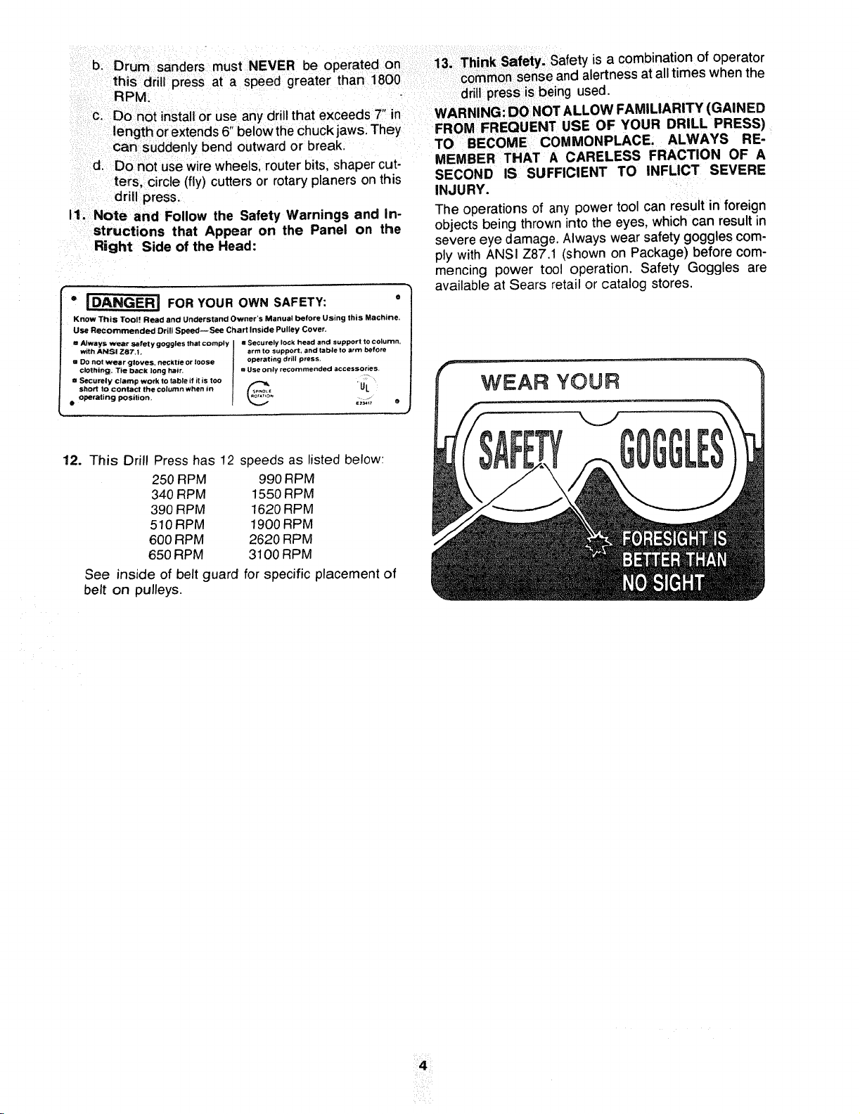
I1. Note and Follow the Safety Warnings and In-
structions that Appear on the Panel on the
Right Side of the Head:
o _ FOR YOUR OWN SAFETY: °
KnOw This Tool Read and Understand Owner'S Manual before Using this Machine,
Use Recommended Drill Speed--See Chart Inside Pulley Cover.
= Always _ S_tFet y goggles that comply mSecurely lock head and support to column.
with ANSI Z87.1. arm to support, and table to arm before
m DO not wear gloves, necktie or loose operating drill press.
c!Othtng, T_e back long hair, u Use only recommended accessories.
• Securely clamp work to table it it is too _ . _
short to contact the column when in /f_p_ UL
• operating position. _ j
12. This Drill Press has 12 speeds as listed below:
250 RPM 990 RPM
340 RPM 1550 RPM
390 RPM 1620 RPM
510 RPM 1900 RPM
600 RPM 2620 RPM
650 RPM 3100 RPM
See inside of belt guard for specific placement of
belt on pulleys.
The operations of any power tool can result in foreign
objects being thrown into the eyes, which can result in
severe eye damage. Always wear safety goggles com-
ply with ANSI Z87.! (shown on Package) before com-
mencing power tool operation. Safety Goggles are
available at Sears retail or catalog stores.
¸¸¸4¸¸¸¸¸
gmossaryof terms
1. Workpiece
The item on which the cutting operations is being
performed.
2. Drill
The cutting toolused in the drill press to make holes
in a workpiece,
3. Backup Material
A piece of wood placed between the workpiece and
table .... it prevents wood in the workpiece from
splintering when the drill passes through the back-
side of the workpiece .... also prevents drilling into
the table top.
4. Revolution Per Minute (R.P.M.)
The number of turns completed by a spinning object
in one minute.
5. Spindle Speed
The RPM of the spindle.
!t,,..
==E
o
m
_._o
table of contents
oE
c
Page
General Safety Instructions for Power Tools ...... 2
Additional Safety Instructions for Drill Presses .... 3
Glossary of Terms .......................... 5
Table of Contents ........................... 5
Motor Specifications and Electrical
Requirements .............................. 6
Unpacking and Checking Contents ............. 7
Table of Loose Parts ........................ 8
cation and Function of Controls .............. 9
sembly ................................ 10
Assembly of Column and Table Hardware.., 10
Installing the Table ..................... 11
Installing the Head ..................... 11
Mounting Motor ........................ 12
Installing Motor Pulley ................... 12
Tensioning Belt ........................ 12
Installing Belt Guard Knob ............... 13
Motor Connections ..................... 14
Installing Feed Handles ................. 14
Installing the Chuck ..................... 14
Installing Light Bulb ..................... 16
Page
Adjusting the Table Square to Head ....... 16
Bevel Scale ........................... 16
Getting to Know Your Drill Press .............. 17
On-Off Switch ......................... 19
Drilling to a Specific Depth ............... 20
Locking Chuck Desired Depth ............ 20
Removing Chuck and Arbor .............. 21
Re-Installing The Chuck and Arbor ........... 22
Basic Drill Press Operation .................. 23
Installing Drills ......................... 23
Positioning Table and Workpiece .......... 24
Tilting Table ........................... 25
Hole Location ......................... 25
Feeding .............................. 25
Adjustments .............................. 25
Quill Return Spring ..................... 25
Maintenance .............................. 26
Lubrication ............................... 26
Recommended Accessories .................. 26
Trouble Shooting .......................... 27
Repair Parts .............................. 28
m m m m
motor specfflcat=ons and electrmca requirements
MOTOR SPECIFICATOONS
This drill press is designed to use a 1725 RPM motor
only. Do not use any motor that runs faster than 1725
RPM It is wired for operation on 110-120 volts, 60 Hz.
alternating current.
WARNING: TO AVOID INJURY FROM UNEX-
PECTED STARTUP, DO NOT USE BLOWER OR
This power tool is equipped with a 3-conductor cord
and grounding type plug. approved by Underwriters'
Laboratories and the Canadian Standards Association,
The ground conductor has a green jacket and is at-
tached to the tool housing at one end and to the ground
prong in the attachment plug at the other end.
This plug requares a mating 3-conductor grounded type
outlet as shown.
WASHING MACHINE MOTORS OR ANY MOTOR
WITH AN AUTOMATIC RESET OVERLOAD PRO-
TECTOR.
CONNECTING TO POWER
SOURCE OUTLET
This machine must be grounded while in use to protect
the operator from electric shock.
Plug power cord into a 110-120V properly grounded
type outlet protected by a 15-amp. dual element time
delay or Circuit breaker.
NOT ALL OUTLETS ARE PROPERLY GROUNDED.
IF YOU ARE NOT SURE THAT YOUR OUTLET, AS
PICTURED BELOW, IS PROPERLY GROUNDED,
HAVE IT CHECKED BY A QUALIFIED ELECTRICIAN.
If the outlet you are planning to use for this power tool
is of the two prong type. DO NOT REMOVE OR ALTER
THE GROUNDING PRONG IN ANY MANNER. Use
an adapter as shown and always connect the grounding
lug to known ground.
It is recommended that you have a qualified electrician
replace the TWO prong outlet with a properly grounded
THREE prong outlet,
An adapter as shown below _savailable for connecting
plugs to 2-prong receptacles.
WARNING: THE GREEN GROUNDING LUG EX-
TENDING FROM THE ADAPTER MUST BE CON-
NECTED TO A PERMANENT GROUND SUCH AS
TO A PROPERLY GROUNDED OUTLET BOX.
WARNING: TO AVOID ELECTRIC SHOCK, DO NOT
TOUCH THE METAL PRONGS ON THE PLUG.
WHEN INSTALLING OR REMOVING THE PLUG TO
OR FROM THE OUTLET.
WARNING: FAILURE TO PROPERLY GROUND THIS
POWER TOOL CAN CAUSE ELECTRICUTION OR
SERIOUS SHOCK, PARTICULARLY WHEN USED IN
DAMP LOCATIONS, OR NEAR METAL PLUMBING.
IF SHOCKED, YOUR REACTION COULD CAUSE
YOUR HANDS TO HIT THE CUTTING TOOL.
IF POWER CORD ISWORN OR CUT, OR DAMAGED
IN ANY WAY, HAVE IT REPLACED IMMEDIATELY
TO AVOID SHOCK OR FIRE HAZARD.
GROUNDING LUG
SCREW \
3-pLPRONG"_ MAKE SURE THIS IS
RECEPTACLE
3-PRONG ADAPTER
PLUG
NOTE: The adapter illustrated is for use only if you
already have a properly grounded 2-prong receptacle.
Adapter isnot allowed in Canada by the Canadian Elec-
trical Code.
\
\
GROUNDING
PRONG
ALWAYS USE A
PROPERLY GROUNDED
OUTLET
The use of any extension cord will cause some loss of
power. To keep this to a minimum and to prevent over-
heating and motor burn-out, use the table below to
determine the minimum wire size (A.W.G.) extension
cord, Use only 3 wire extension cords which have 3-
prong grounding type plugs and 3-pole receptacles
which accept the tools plug.
Your unit isfor use on !20 volts. It has a plug that looks
like the one above.
Extension Cord Length Wire Size A.W.G,
0-25 Feet 16
26-50 Feet 14
51-100 Feet 12
6

unpacking and
checking
contents
WARNING: TO AVOID INJURY FROM UNEX-
pECTED STARTING OR ELECTRICAL SHOCK, DO
_OT PLUG THE POWER CORD INTO A SOURCE
OF POWER. THIS CORD MUST REMAIN UNPLUG-
GED WHENEVER YOU ARE WORKING ON THE
DRILL PRESS.
Model 113.2!3150 Drill Press is shipped complete in
one box.
1. Unpacking and Checking Contents
a. Separate all "loose parts" from packaging mate-
rials and check each item with "Table of Loose
Parts" to make sure all items are accounted for,
before discarding any packing material. Some
loose parts are contained inside the belt guard,
Open the belt guard cover to find them.
WARNING: IF ANY PARTS ARE MISSING, DO NOT
ATTEMPT TO ASSEMBLE DRILL PRESS, PLUG IN
THE POWER CORD, OR TURN THE SWITCH ON
UNTIL THE MISSING PARTS ARE OBTAINED AND
ARE INSTALLED CORRECTLY.
2. Remove the protective oil that is applied to the
table and column. Use any ordinary household type
grease and spot remover.
WARNING: TO AVOID FIRE OR TOXIC REAC-
TION, NEVER USE GASOLINE, NAPTHA OR
SIMILAR HIGHLY VOLATILE SOLVENTS.
3. Apply a coat of paste wax to the table and column
to prevent rust. Wipe all parts thoroughly with a clean
! dry cloth.
TABLE OF LOOSE PARTS
Item Description Qty.
A Table .............................. 1
B Column Support Asm .................. 1
C Owner's Manual ...................... 1
D Motor .............................. 1
E Bag of Loose Parts ................... 2
F Base ............................... 1
G Head Asm ........................... 1
H Box of Loose Parts ................... 1
o'}o
O
H
F
E
D
C
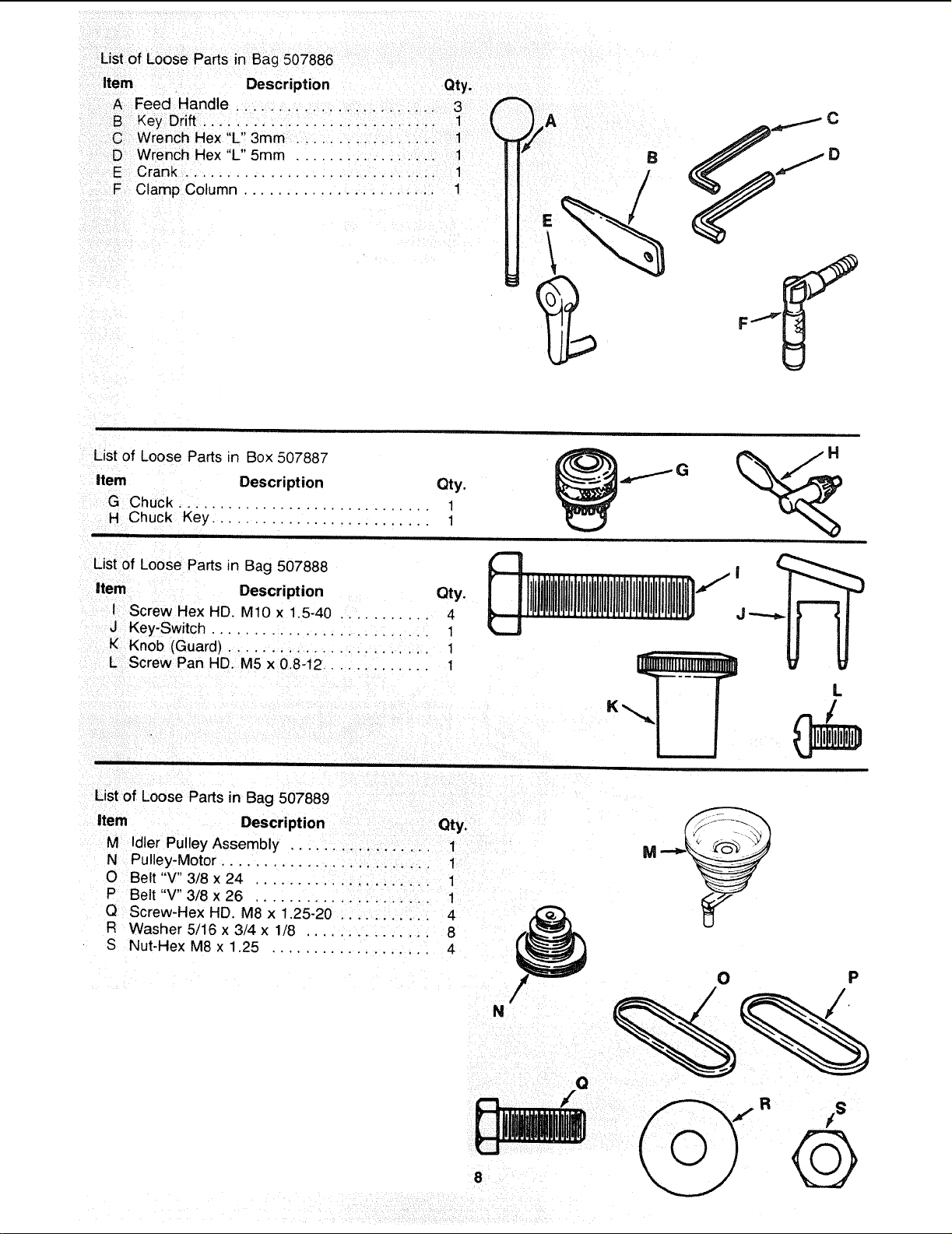
List of Loose Parts in Bag 507886
Item Description Qty.
A Feed Handle ........................ 3
B Key Drift ................. 1 t
C Wrench Hex "L" 3mm ................. 1
D Wrench Hex "L" 5mm ................. 1
E Crank .............................. 1
F Clamp Column ...................... 1
B
List of Loose Parts in Box 507887
Item Description Qty.
G Chuck
.............................. 1
H Chuck Key .......................... 1
List of Loose Parts in Bag 507888
item Description Qty.
I Screw Hex HD. MIO x 1.5-40 ........... 4
J Key-Switch .......................... 1
K Knob (Guard) ........................ 1
L Screw Pan HD. M5 x 0.8-12 ............ 1
J "-,.-...lb.
L
K
List of Loose Parts in Bag 507889
item Description Qty.
M Idler Pulley Assembly ................. 1
N Pulley-Motor ......................... 1
O Belt "V" 3/8 x 24 ..................... 1
P Belt "V" 3/8 x 26 ..................... 1
Q Screw-Hex HD. M8 x 1.25-20 ........... 4
F_ Washer 5/16 x 3/4 x 1/8 ............... 8
S Nut-Hex M8 x 1.25 ................... 4
N

location and function of controls
1. BELT TENSION HANDLE... Turn handle counter
clockwise to apply tension to bell turn handle
clockwise to release belt tension.
2. BELT TENSION LOCK HANDLES... Tightening
handles locks motor bracket support and BELT
TENSION HANDLE to maintain correct belt dis-
tance and tension.
3. HEAD LOCKS... Lock the head to the column,
ALWAYS have them locked in place while operat-
ing the drill press,
4. SUPPORT LOCK... Tightening locks table sup-
port to column. Always have it locked in place while
operating the Drill Press.
5. TABLE CRANK . . . Turn clockwise to elevate
table. Support lock must be released before operat-
ing crank.
6. TABLE BEVEL LOCK... Locks the table in any
position from 0'_-45 _
7. TABLE LOCK . . . Allows table to be rotated in
various positions and locked.
8. FEED HANDLE . . . For moving the quill up or
down. One or two may be removed if necessary
whenever the workpiece is of such unusual shape
that it interferes with the handles.
2
10
7
TABLE REMOVED
FOR CLARITY
9. CHUCK... Holds drill bit or other recommended
accessory to perform desired operations.
10. BEVEL SCALE... Shows degree table is tilted
for bevel operations, Scale is mounted on side of
arm.
11. SPRING CAP... Provides means to adjust quill
spring tension
12. DEPTH SCALE... Allows operator to adjust drill
press to drill to a desired depth.
13. DRILL "ON-OFF" SWITCH . . . Turns drill press
on and off .... also used to lock drill press in off
position.
14. LIGHT "ON-OFF" SWITCH,.. Turns the light on
and off.
15. CHUCK KEY... Used to tighten drill in the chuck
and also to loosen the chuck for drill removal.
16. DEPTH SCALE LOCK... Locks the depth scale
at selected position.
16
14
\
13
¢t)
0
(.3
"_€:
o o
0_-.
1--
IJ-
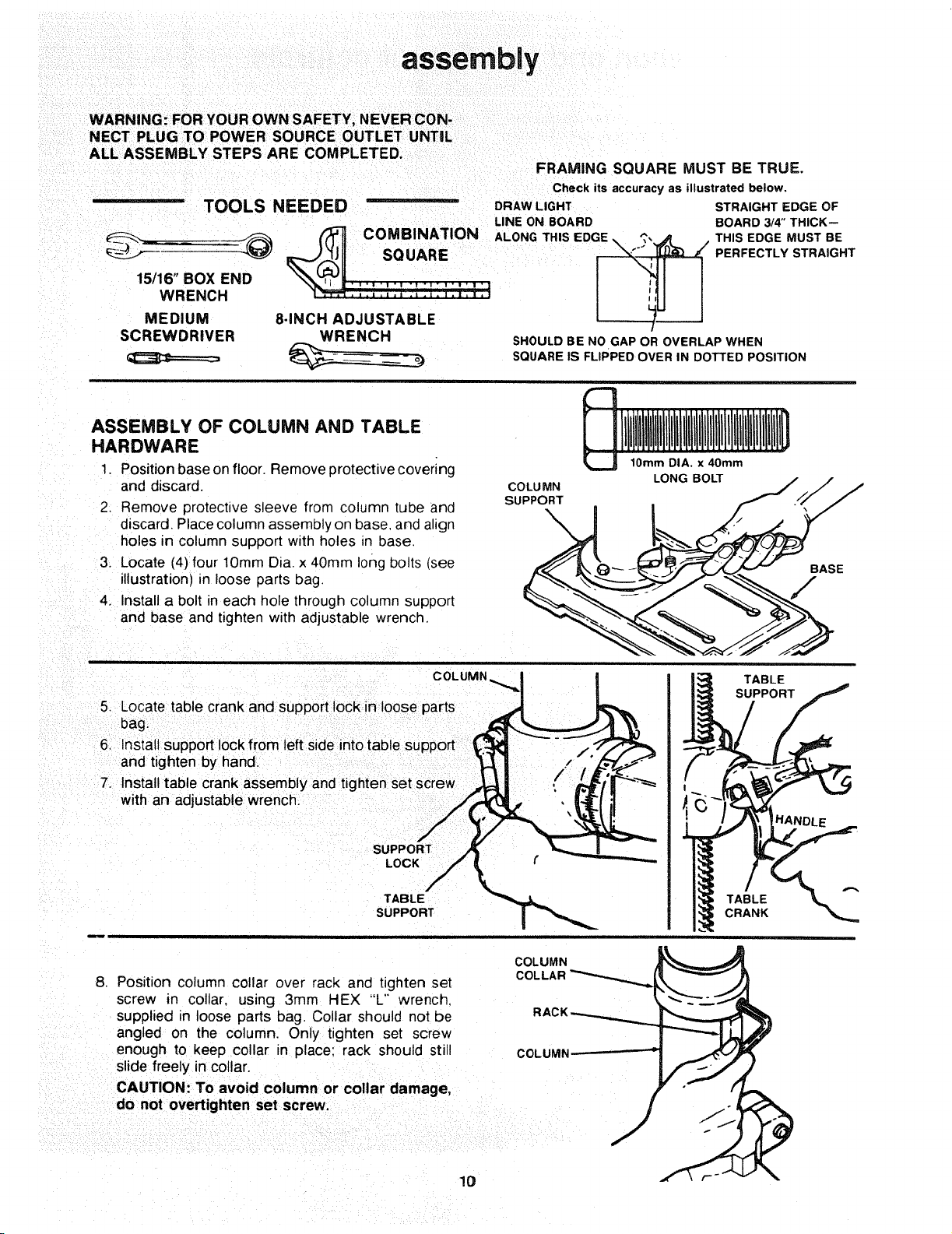
assembly
WARNING: FOR YOUR OWN SAFETY, NEVER CON-
NECT PLUG TO POWER SOURCE OUTLET UNTIL
ALL ASSEMBLY STEPS ARE COMPLETED.
FRAMING SQUARE MUST BE TRUE.
Check itsaccuracy as illustrated below.
-- TOOLS NEEDED DRAWLIGHT STRAIGHT EDGE OF
LINE ON BOARD BOARD 3/4"THICK--
15/16" BOX END ..... , . .,+, .... .
MEDIUM 8-INCH ADJUSTABLE
SCREWDRIVER WRENCH
SHOULD BE NO GAP OR OVERLAP WHEN
SQUARE IS FLIPPED OVER IN DOTTED POSITION
ASSEMBLY OF COLUMN AND TABLE
HARDWARE
1. Position base on floor. Remove protective covering
and discard.
2, Remove protective sleeve from column tube and
discard. Place column assembly on base, and align
holes in column support with holes _n base.
3. Locate (4) four lOmm Dia. x 40mm long bolts (see
illustration) in loose parts bag.
4. Install a bolt in each hole through column support
and base and tighten with adjustable wrench.
COLUMN
SUPPORT
10ram DIA, x 40mm
LONG BOLT
BASE
F
COLUMN
5. Locate table crank and support lock in loose parts
bag.
6+ Install support lock from left side into table support
and tighten by hand.
7+ Install table crank assembly and tighten set screw
with an adjustable wrench,
SL
LOCK
TABLE
SUPPORT
TABLE
SUPPORT
TABLE
CRANK
8. Position column collar over rack and tighten set
screw in collar, using 3ram HEX "L'" wrench.
supplied in loose parts bag. Collar should not be
angled on the column. Only tighten set screw
enough to keep collar in place: rack should still
slide freely in collar.
CAUTION: To avoid column or collar damage,
do not overtighten set screw.
COLUMN
COLLAR
COLUMN
10
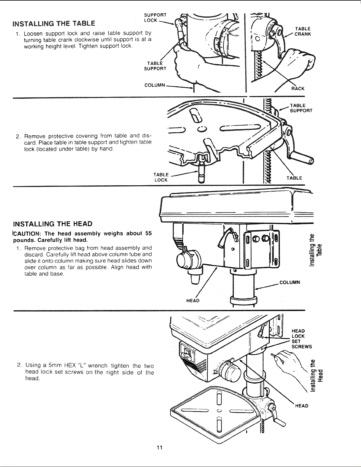
INSTALLING THE TABLE
SUPPORT
LOCK
1. Loosen support lock and raise table support by
turning table crank clockwise until support is at a
working height level. Tighten support lock,
TABLE
SUPPORT
TABLE
:RANK
RACK
.,,...._TABLE
SUPPORT
2. Remove protective covering from table and dis-
card. Place table in table support and tighten table
lock (located under table) by hand.
TABLE
LOCK
TABLE
iNSTALLING THE HEAD
_CAUTION: The head assembly weighs about 55
pounds. Carefully lift head.
1. Remove protective bag from head assembly and
discard. Carefully lift head above column tube and
slide it onto column making sure head slides down
over column as far as possible. Align head with
table and base.
COLUMN
HEAD
HEAD
LOCK
SET
SCREWS
2. Using a 5mm HEX "L" wrench tighten the two
head lock set screws on the right side of the
head.
C
'_uc
C
11
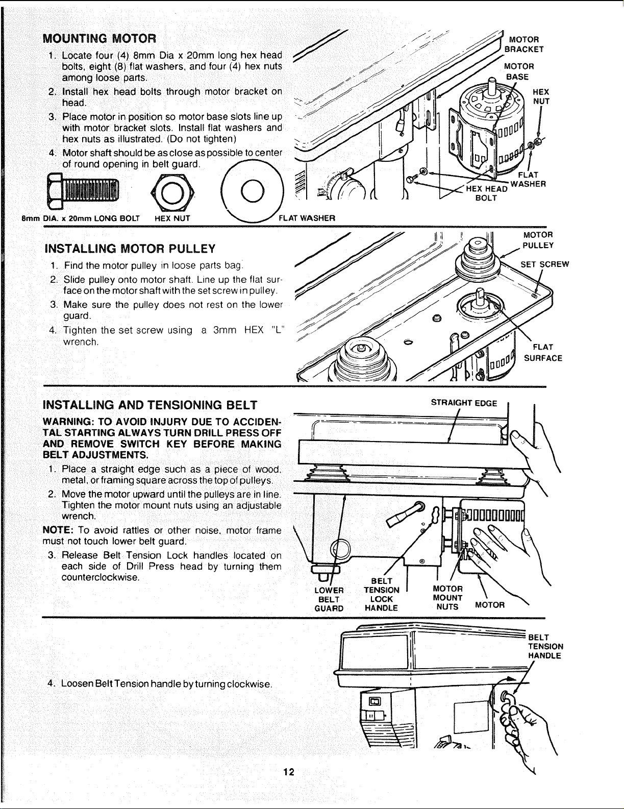
MOUNTING MOTOR _J .f'_ S_
FF"
S*
1. Locate four (4) 8mm Dia x 20mm long hex head z j"
bolts, eight (8) flat washers, and four (4) hex nuts "_
S!
among loose parts. _ _ _ y
2. head.Installhex head bolts through motor bracket on _"
3. Place motor in position so motor base slots line up • -------------------_
with motor bracket slots. Install flat washers and
hex nuts as illustrated. (Do not tighten)
4. Motor shaft should be as close as possible to center
of round opening in belt guard.
8mm DIA. x 20ram LONG BOLT HEX NUT
i
AT WASHER
iNSTALLiNG MOTOR PULLEY
1 Find the motor pulley in loose parts bag.
2. Slide pulley onto motor shaft. Line up the flat sur-
face on the motor shaft with the set screw m pulley.
3. Make sure the pulley does not rest on the lower
guard.
4. Tighten the set screw using a 3ram HEX "L
wrench.
HEAD
BOLT
MOTOR
BRACKET
MOTOR
BASE
HEX
NUT
FLAT
WASHER
MOTOR
PULLEY
SET SCREW
FLAT
SURFACE
INSTALLING AND TENSIONING BELT
STRAIGHT EDGE
WARNING: TO AVOID INJURY DUE TO ACCIDEN- ,,f_
TAL STARTING ALWAYS TURN DRILL PRESS OFF H
AND REMOVE SWITCH KEY BEFORE MAKING |
BELT ADJUSTMENTS.
I
Tighten the motor mount nuts using an adjustable
wrench.
NOTE: To avoid rattles or other noise, motor frame _,
k
must not touch lower belt guard. \
/
3. Release Belt Tension Lock handles located on \
each side of Drill Press head by turning them
counterclockwise.
4. Loosen Belt Tension handle by turning clockwise.
12
BELT
LOWER TENSION MOTOR
BELT LOCK MOUNT
GUARD HANDLE NUTS
MOTOR
BELT
TENSION
HANDLE

5. Locate center pulley assembly in loose parts bag
and place in proper hole.
SPINDLE PULLEY
6. Locate two (2) V-belts in the loose parts bag.
7. Use speed chart inside belt guard to choose speed
for drilling operation. Install belts in correct position
for desired speed. The longer of the two belts is
always positioned between the spindle pulley and
idler pulley.
NOTE: Refer to chart inside belt guard for Recom-
mended Drilling Speeds.
8. Apply tension to belt by turning Belt Tension Handle
counter clockwise until belt deflects approximately
1/2 inch by thumb pressure at its center.
9. Tighten Belt Tension Lock Handles.
CAUTION: Over tensioning belt may cause motor not
start or damage bearings.
,0. If belt slips while drilling, readjust belt tension.
IDLER PULLEY
BELT
TENSION
LOCK
-_ HANDLE
BELT
TENSION
HANDLE
BELT GUARD KNOB
5rnmDIA.x12mm LONG
SCREW
BELT GUARD KNq
PAN HD.
INSTALLING BELT GUARD KNOB
1. To attach belt guard knob, locate knob and 5mm
Dia. x12mm long pan hd. screw in loose parts bag.
Install screw in hole located in guard and attach
knob turning until tight,
WARNING: TO AVOID POSSIBLE INJURY KEEP
GUARD IN PLACE AND IN PROPER WORKING
ORDER WHILE OPERATING.
BELT GUARD
13
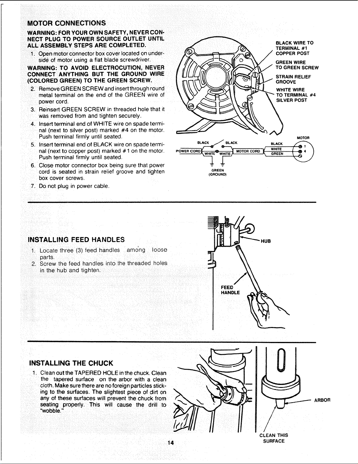
MOTOR CONNECTIONS
WARNING: FOR YOUR OWN SAFETY, NEVER CON-
NECT PLUG TO POWER SOURCE OUTLET UNTIL
ALL ASSEMBLY STEPS ARE COMPLETED.
power cord.
3. Reinsert GREEN SCREW in threaded hole that it
was removed from and tighten securely.
4. Insert terminal end of WHITE wire on spade _ermi-
nal (next to silver post) marked #4 on the motor.
Push terminal firmly until seated.
5. Insert terminal end of BLACK wire on spade termi-
nal (next to copper post) marked # 1 on the motor.
Push terminal firmly until seated.
6. Close motor connector box being sure that power
cord is seated in strain relief groove and tighten
box cover screws.
BLACK WIRE TO
TERMINAL #1
COPPER POST
_,\V _",_ I1 ""_t_--_3. WHITE WIRE
MOTOR
.ow°. .o.o.oo.°w.,.;.
GREEN
(GROUND)
7. Do not plug in power cable.
INSTALLING FEED HANDLES
1. Locate three (3) feed handles amo'ng leose
parts.
2. Screw the feed handles into the threaded holes
inthe hub and tighten.
FEED
HANDLE
HUB
INSTALLING THE CHUCK
1. Ctean out the TAPERED HOLE inthe chuck, Clean
the tapered surface on the arbor with a clean
cloth. Make sure there are no foreign particles stick-
ing to the surfaces. The slightest piece of dirt on
any of these surfaces will prevent the chuck from
seating properly. This wilt cause the drill to
"wobble."
14
CLEAN THIS
SURFACE
ARBOR

2. Slide the chuck up over the arbor as illustrated.
SPINDLE
JC:
_D
IC:
.m
_J
C
4. Unlock support lock and raise table so its about
two (2) inches below tip of chuck.
5. Turn chuck sleeve clockwise and open jaws in
chuck completely.
6. Turn feed handles counterclockwise and force
chuck against table until chuck is secure.
SUPPORT
LOC.K
N
FEED
HANDLE
15
CHUCK
SLEEVE
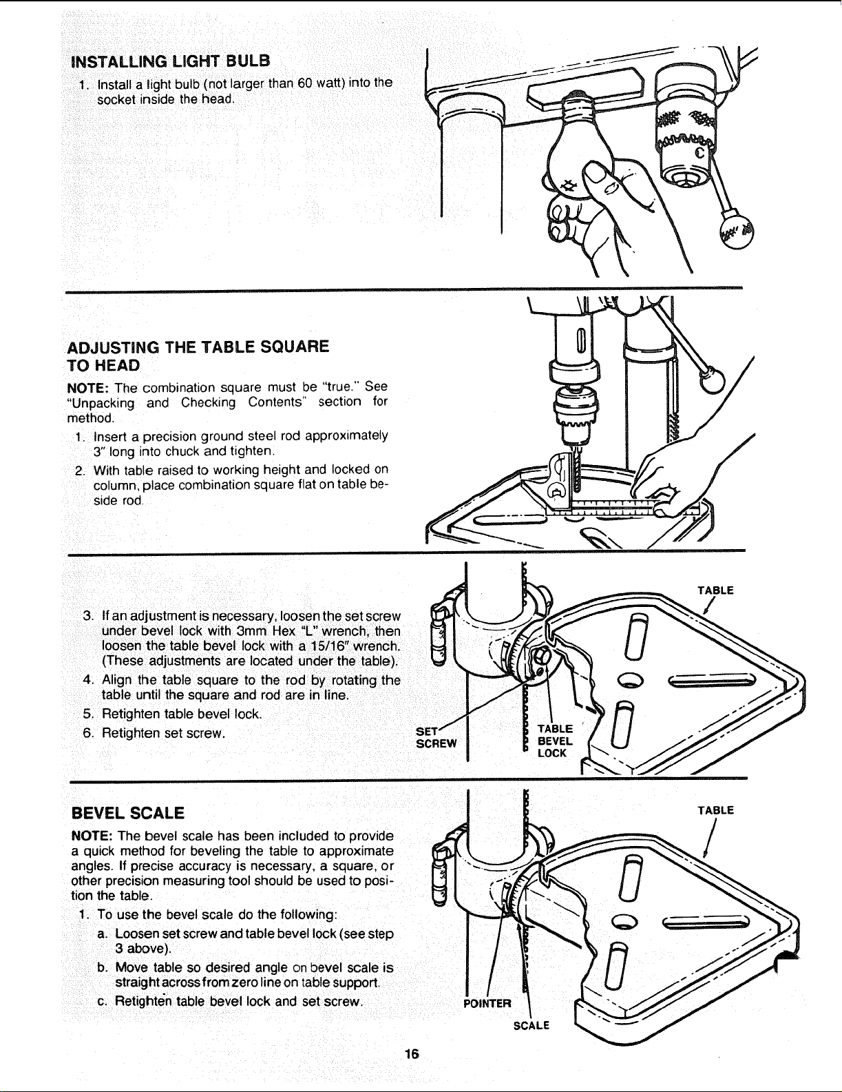
INSTALLING LIGHT BULB
1. Installa lightbulb (not larger than 60 watt) intothe
socket inside the head,
ADJUSTING THE TABLE SQUARE
TO HEAD
NOTE: The combination square must be "true." See
"Unpacking and Checking Contents" section for
method.
1, Insert a precisionground steel rod approximately
3"long into chuck and tighten.
2. With table raised to working height and locked on
column,place combinationsquare flaton table be-
side rod
3. If an adjustment is necessary loosen the set screw
V "
under be e lock wth 3mm Hex L wrench, then
loosen the table bevel lock with a 1 5/16" wrench.
(These adjustments are located under the table).
4. Align the table square to the rod by rotating the
tal31euntil the square and rod are in line.
5. Retighten table bevel lock.
6. Retighten set screw.
SCREW
TABLE
BEVEL
LOCK
TABLE
/
/
BEVEL SCALE / ! TABLE
J L
/
a quick method for beveling the table to approximate _!_ _ ' L_._"_-_-'__ /
angles. If precise accuracy is necessary, a square, or IL_I \_..:._. _,r_,,,,_ _1 .,,,_,,_
other precision measuringtool should be used to posi- L,'] I :_,'_ ,_ I ! _._
tion the table, r_! | _ (]_ "_-_. _ U _'_._
1. TOuse the bevel scale do the following: _=__ "_ _ -'__
a. Loosen setscrew and table bevel lock(see step I 11 _ _ -_) _ t,_/"_._
3above), I / : _'_ _ .-'_J
b. Move table so desired angle on bevel scale is I / ! / / /
straight across from zero line on table support. I/ i
C. Retighten table bevel lock and set screw. POINTER / _*_--_J/
SCALE
16
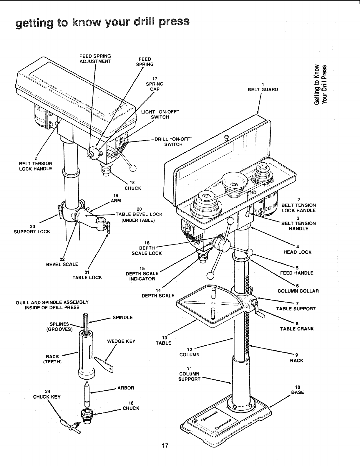
getting to know your drill press
FEED SPRING
ADJUSTMENT
FEED
SPRING
17
SPRING
CAP
LIGHT "ON-OFF"
SWITCH
1
BELT GUARD
/
c_
_L
O_
DRILL "ON-OFF"
SWITCH
2
BELT TENSION
LOCK HANDLE
23
SUPPORT LOCK
22
BEVEL SCALE
/
21
TABLE LOCK
QUILL AND SPINDLE ASSEMBLY
INSIDE OF DRILL PRESS
SPLINES
(GROOVES)
RACK
(TEETH)
18
CHUCK
19
ARM
20
BEVEL LOCK
(UNDER TABLE)
16
DEPTH
SCALE LOCK
15
DEPTH SCALE
INDICATOR
SPINDLE
14
DEPTH SCALE
WEDGE KEY
13
TABLE
24 _ ._..._ ARBOR
CHUCK KEY U 18
12
COLUMN
11
COLUMN
SUPPC
17
2
BELT TENSION
LOCK HANDLE
3
BELT TENSION
HANDLE
4
HEAD LOCK
5
FEED HANDLE
6
COLUMN COLLAR
7
TABLE SUPPORT
B
TABLE CRANK
10
BASE
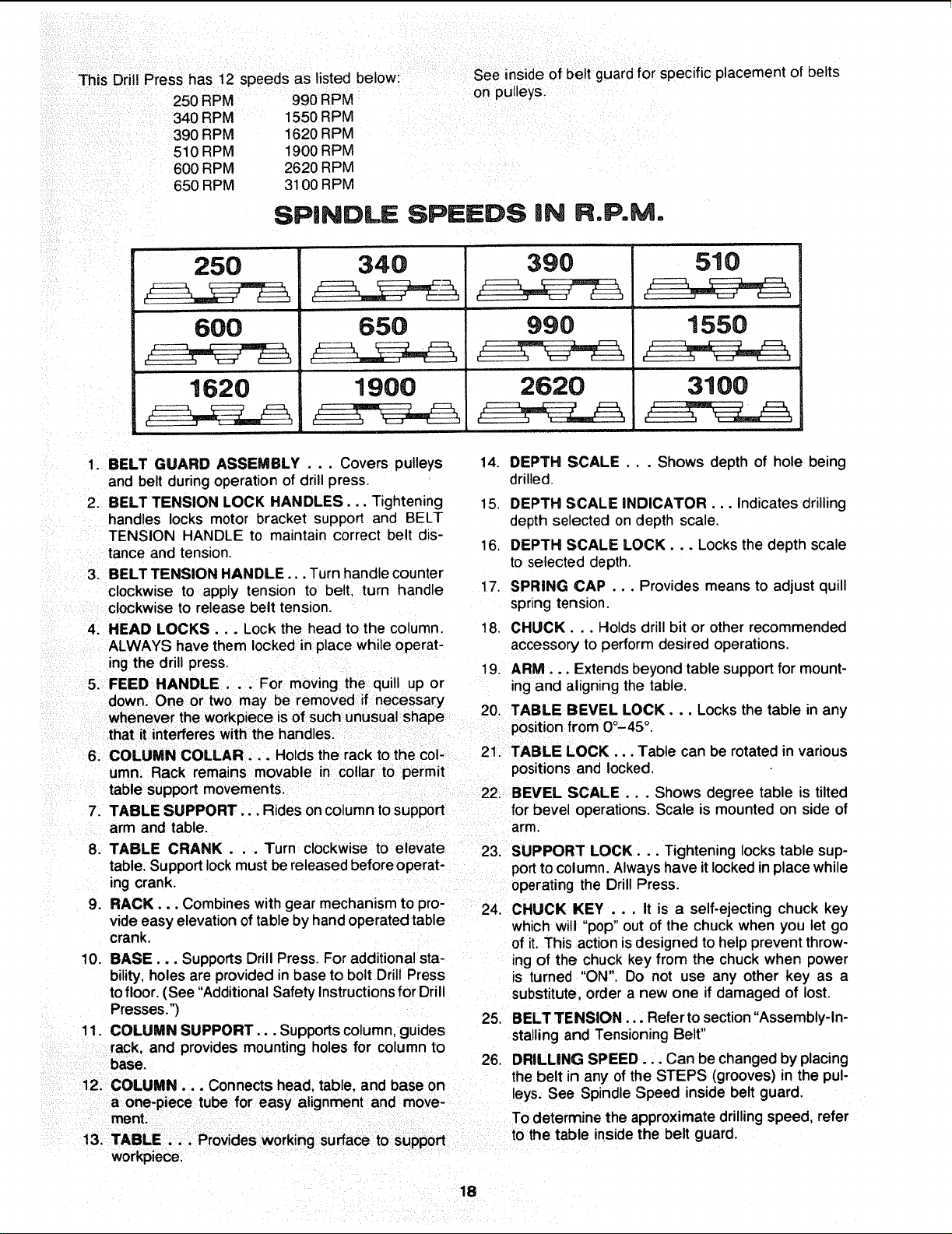
This Drill Press has 12 speeds as listed below:
250 RPM 990 RPM
340 RPM 1550 RPM
390 RPM 1620 RPM
510 RPM 1900 RPM
600 RPM 2620 RPM
650 RPM 3100 RPM
See inside of belt guard for specific placement of belts
on pulleys.
SPINDLE SPEEDS iN R,P.M.
250
600
1620
340
65O
1900
390
990
2620
510
1550
, r,
3100
1. BELT GUARD ASSEMBLY . .. Covers pulleys
and belt during operation of drill press.
2. BELT TENSION LOCK HANDLES... Tightening
handles locks motor bracket support and BELT
TENSION HANDLE to maintain correct belt dis-
tance and tension.
3. BELT TENSION HANDLE... Turn handle counter
clockwise to apply tension to belt. turn handle
clockwise to release belt tension.
4. HEAD LOCKS... Lock the head to the column.
ALWAYS have them locked in place while operat-
ing the drill press,
5. FEED HANDLE . .. For moving the quill up or
down. One or two may be removed if necessary
6. COLUMN COLLAR... Holds the rackto the col-
umn. Rack remains movable in collar to permit
table support movements.
7. TABLE SUPPORT... Rides oncolumn tosupport
arm and table.
8. TABLE CRANK . . . Turn clockwise to elevate
table, Supportlockmust bereleasedbefore operat-
ing crank.
9. RACK... Combines with gear mechanismto pro-
vide easy elevation oftable by handoperated table
crank,
10. BASE,.. SupportsDrill Press. Foradditional sta-
bility, holesare provided in base to bolt Drill Press
tofloor. (See "Additional Safety Instructionsfor Drill
Presses.")
11. COLUMN SUPPORT... Supportscolumn,guides
rack, and provides mounting holes for column to
base.
12. COLUMN... Connects head, table, and base on
a one-piece tube for easy alignment and move-
workpiece.
support
14. DEPTH SCALE... Shows depth of hole being
drilled.
15. DEPTH SCALE INDICATOR... Indicates drilling
depth selected on depth scale.
16. DEPTH SCALE LOCK... Locks the depth scale
to selected depth.
17. SPRING CAP ... Provides means to adjust quill
spnng tension.
18. CHUCK... Holds drill bit or other recommended
accessory to perform desired operations.
19. ARM... Extends beyond table supportfor mount-
ingand aligning the table.
20. TABLE BEVEL LOCK... Locks the table in any
positionfrom 00-45 °.
21. TABLE LOCK,.. Table can be rotated in various
positions and locked,
22. BEVEL SCALE... Shows degree table is tilted
for bevel operations. Scale is mounted on side of
arm,
23. SUPPORT LOCK... Tightening locks table sup-
portto column.Always have itlockedin place while
operating the Drill Press.
24. CHUCK KEY .. , It is a self-ejecting chuck key
which will "pop" out of the chuck when you let go
of it. This action isdesigned to help prevent throw-
ing of the chuck key from the chuck when power
is turned "ON", Do not use any other key as a
substitute, order a new one if damaged of lost.
25, BELTTENSION... Referto section"Assembly-In-
stalling and Tensioning Belt"
26. DRILLING SPEED... Can be changed by placing
the belt in any ofthe STEPS (grooves) in the pul-
leys. See Spindle Speed inside belt guard,
To determine the approximate drillingspeed, refer
to the table inside the belt guard.
18
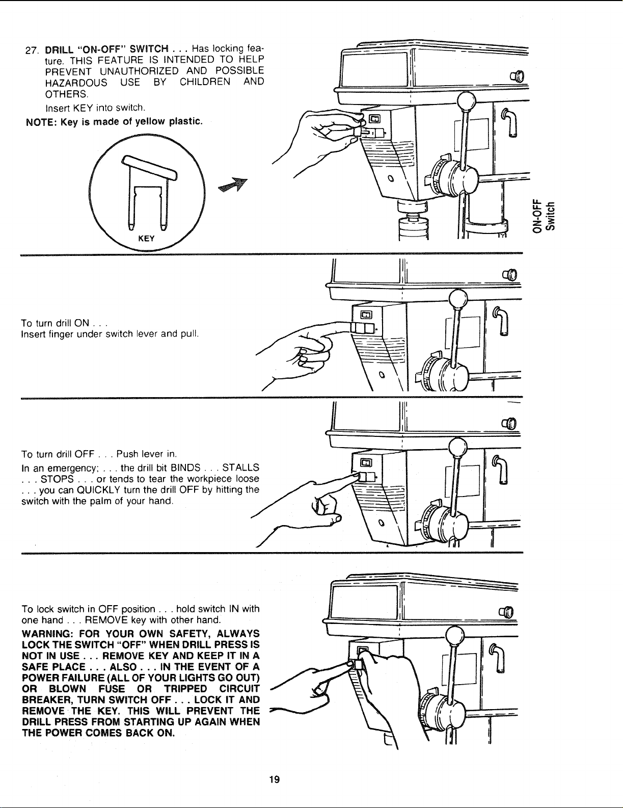
27. DRILL "ON-OFF" SWITCH . .. Has locking fea-
ture, THIS FEATURE IS INTENDED TO HELP
PREVENT UNAUTHORIZED AND POSSIBLE
HAZARDOUS USE BY CHILDREN AND
OTHERS.
Insert KEY into switch,
NOTE: Key is made of yellow plastic.
To turn drill ON.. ,
Insert finger under switch lever and pull.
.yd
II
i
\
M,.
oO_
To turn drill OFF... Push lever in.
In an emergency; ... the drill bit BINDS... STALLS
• . . STOPS . . . or tends to tear the workpiece loose
• • . you can QUICKLY turn the drill OFF by hitting the
switch with the palm of your hand.
/
To lock switch in OFF position.., hold switch IN with
one hand... REMOVE key with other hand.
WARNING: FOR YOUR OWN SAFETY, ALWAYS
LOCK THE SWITCH "OFF" WHEN DRILL PRESS IS
NOT IN USE . .. REMOVE KEY AND KEEP IT IN A
SAFE PLACE . . . ALSO . . . IN THE EVENT OF A
POWER FAILURE (ALL OF YOUR LIGHTS GO OUT)
OR BLOWN FUSE OR TRIPPED CIRCUIT
BREAKER, TURN SWITCH OFF... LOCK iT AND
REMOVE THE KEY. THIS WILL PREVENT THE
DRILL PRESS FROM STARTING UP AGAIN WHEN
THE POWER COMES BACK ON.
19
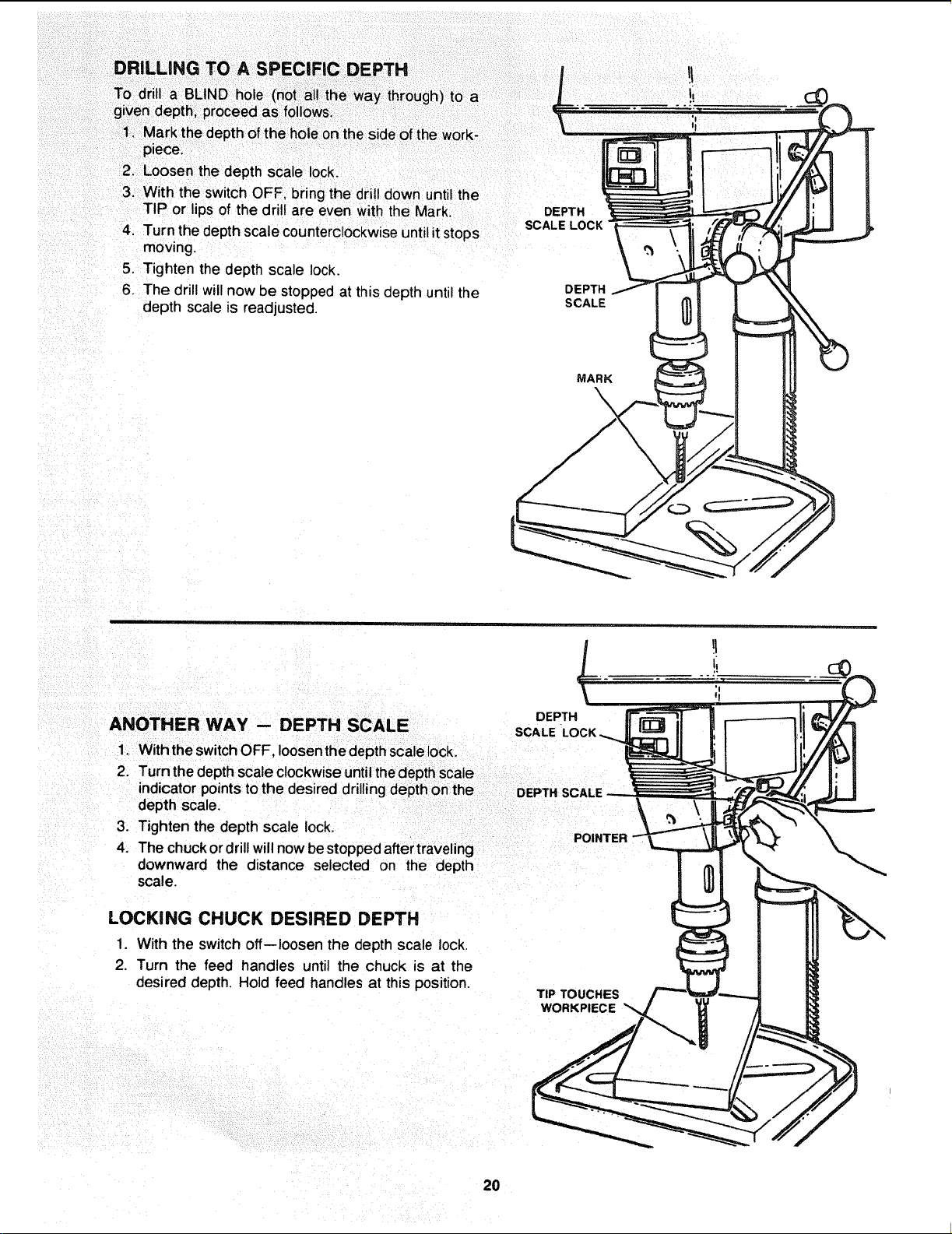
piece.
2- Loosen the depth scale lock.
3. With the switch OFF, bring the drill down until the
TIP or lips of the drill are even with the Mark. DEPTH
SCALE LOCK
4. Turn the depth scale counterclockwiseuntilitstops
moving.
5. Tighten the depth scale lock.
6. The drill willnow Destopped at this depth until the DEPTH
depth scale is readjusted. SCALE
MARK
\
DEPTH
ANOTHER WAY -- DEPTH SCALE SCALE
1. WiththeswitchOFF, loosenthedepth scalelock.
2. Turn the depthscale clockwiseuntilthedepthscale
indicator pointsto the desired drillingdepthon the
depth scale.
3. Tighten the depth scale lock.
POINTER
4. The chuckordrillwillnowbestopped aftertraveling
downward the distance selected on the depth
scale.
LOCKING CHUCK DESIRED DEPTH
1. With the switch off--loosen the depth scale lock.
2. Turn the feed handles until the chuck is at the
desired depth Hold feed handles at this position.
TIP TOUCHES
WORKPIECE
20
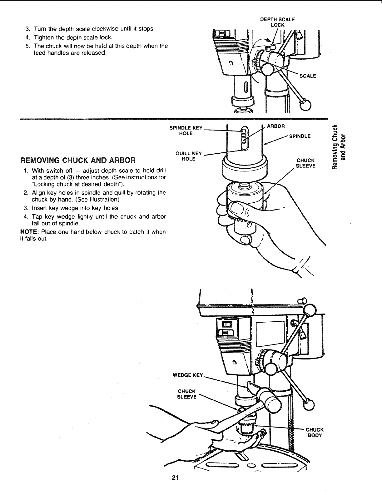
3. Turn the depth scale clockwise until it stops.
4. Tighten the depth scale lock.
5. The chuck will now be he_d at this depth when the
feed handles are released.
DEPTH SCALE
LOCK
REMOVaNG CHUCK AND ARBOR
1. With switch off -- adjust depth scale to hold drill
at a depth of (3) three inches. (See instructionsfor
"Locking chuck at desired depth").
2, Align key holes in spindle and quill by rotating the
chuck by hand. (See illustration)
3, Insert key wedge into key holes.
4, Tap key wedge lightly until the chuck and arbor
fall out of spindle,
NOTE: Place one hand below chuck to catch it when
it falls out.
SPINDLE KEY
HOLE
QUILL KEY
HOLE
ARBOR
SPINDLE
CHUCK
SLEEVE
=3c
WEDGE KEY
CHUCK
SLEEVE
BODY
21
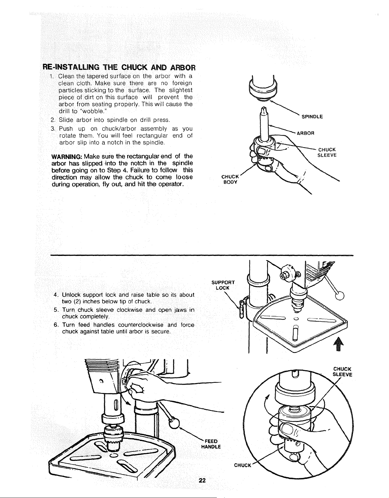
RE'INSTALLING THE CHUCK AND ARBOR
1. Clean the tapered surface on the arbor with a
clean cloth. Make sure there are no foreign
particles stickingto the surface. The slightest
piece of dirt on this surface will prevent the
arbor from seating properly. This will cause the
drill to "wobble."
2. Slide arbor into spindle on drill press.
3. Push up on chuck/arbor assembly as you
rotate them. You will feel rectangular end of
arbor slip into a notch in the spindle.
WARNING: Make sure the rectangular end of the
arbor has slipped .into the notch in the spindle
before going on to Step 4. Failure to follow this
direction may allow the chuck to come loose
during operation, fly out, and hit the operator.
CHUCK
BODY
SPINDLE
ARBOR
CHUCK
SLEEVE
SUPPORT
LOCK
4. Unlock support lock and raise table so its about
two (2) inches below tip of chuck.
5. Turn chuck sleeve clockwise and open jaws in
chuck completely.
6. Turn feed handles counterclockwise and force
chuck against table until arbor is secure.
CHUCK
SLEEVE
FEED
HANDLE
CHI
22
basic drill press operation
Follow the following instructionsfor operating your drill
press to get the best results and to minimize the likeli-
hood of personal injury.
WARNING: FOR YOUR OWN SAFETY, ALWAYS
OBSERVE THE SAFETY PRECAUTIONS HERE AND
ON PAGES 2, 3, AND 4.
1. Protection: Eyes, Hands, Face, Ears and Body
WARNING: TO AVOID BEING PULLED iNTO
THE SPINNING TOOL --
a.
b.
c,
d.
1. Do NOT wear:
-- gloves
-- necktie
-- loose clothing
-- jewelry
2. Do tie back long hair
Ifany part of your drill press is missing, malfunc-
tioning,- has been damaged or broken.., such
as the motor switch, or other operating control,
a safety device or the power cord . . . cease
operating immediately until the particular part
is properly repaired or replaced.
Never place your fingers in a position where
they could contact the drill or other cutting tool
if the workpiece should unexpectedly shift or
your hand should slip.
To avoid injury from parts thrown by the spring,
follow instructions exactly as given and shown
in adjusting spring tension of quill.
To prevent the workpiece from being torn from
your hands, spinning of the tool, shattering the
tool or being thrown, always properly support
your work so it won't shift or bind on the tool:
-- Always position BACKUP MATERIAL (use
beneath the workpiece) to contact the left
side of the column.
-- Whenever possible, position the WORK-
PIECE to contact the left side of the col-
umn-if it is too short o.r the table is tilted.
clamp solidly to the table, use table slots or
clamping ledge around the outside edge of
the table.
-- When using adrill press VICE, always fasten
it to the table.
- Never do any work "FREEHAND" (hand-
holding workpiece rather than supporting it
on the table), except when polishing.
-- Securely lock Head and Support to Column,
Table Arm to support, and Table to Table
Arm before operating drill press.
-- Never move the Head or Table while the
tool is running.
-- Before starting the operation, jog the motor
switch to make sure the drill or other cutting
tool does not wobble or cause vibration.
-- If a workpiece overhangs the table such taht
it will fall or tip if not held, clamp it to the
table or provide auxiliary support.
- Use fixtures for unusual operations to
adequately hold, guide and position work-
piece.
- Use the SPINDLE SPEED recommended
for the specific operation and workpiece ma-
terial-check the panel inside of the guard
cover for drilling information; for acces-
sories, refer to the instructions provided
with the accessories,
f. Never climb on the drill press Table, it could
break or pul! the entire drill press down on you.
g. Turn the motor Switch Off and put away the
Switch Key when leaving the drill press.
h. To avoid injury from thrown work or tool contact,
do NOT perform layout, assembly, or setup
work on the table while the cutting tool is rotat-
ing.
2. Use only accessories designed for this drill
press to avoid serious injury from thrown bro-
ken parts or work pieces.
a. Hotesaws must NEVER be operated on this drill
press at a speea greater than 400 RPM
b. Drum sanders must NEVER be operated on
this drill press at a speed greater than 1800
RPM
c. Do not install or use any drill that exceeds 7" in
length or extends 6" below the chuck jaws. They
can suddenly bend outward or break.
d. Do not use wire wheels, router bits, shaper cut-
ters, circle (fly) cutters or rotary planers on the
drill press.
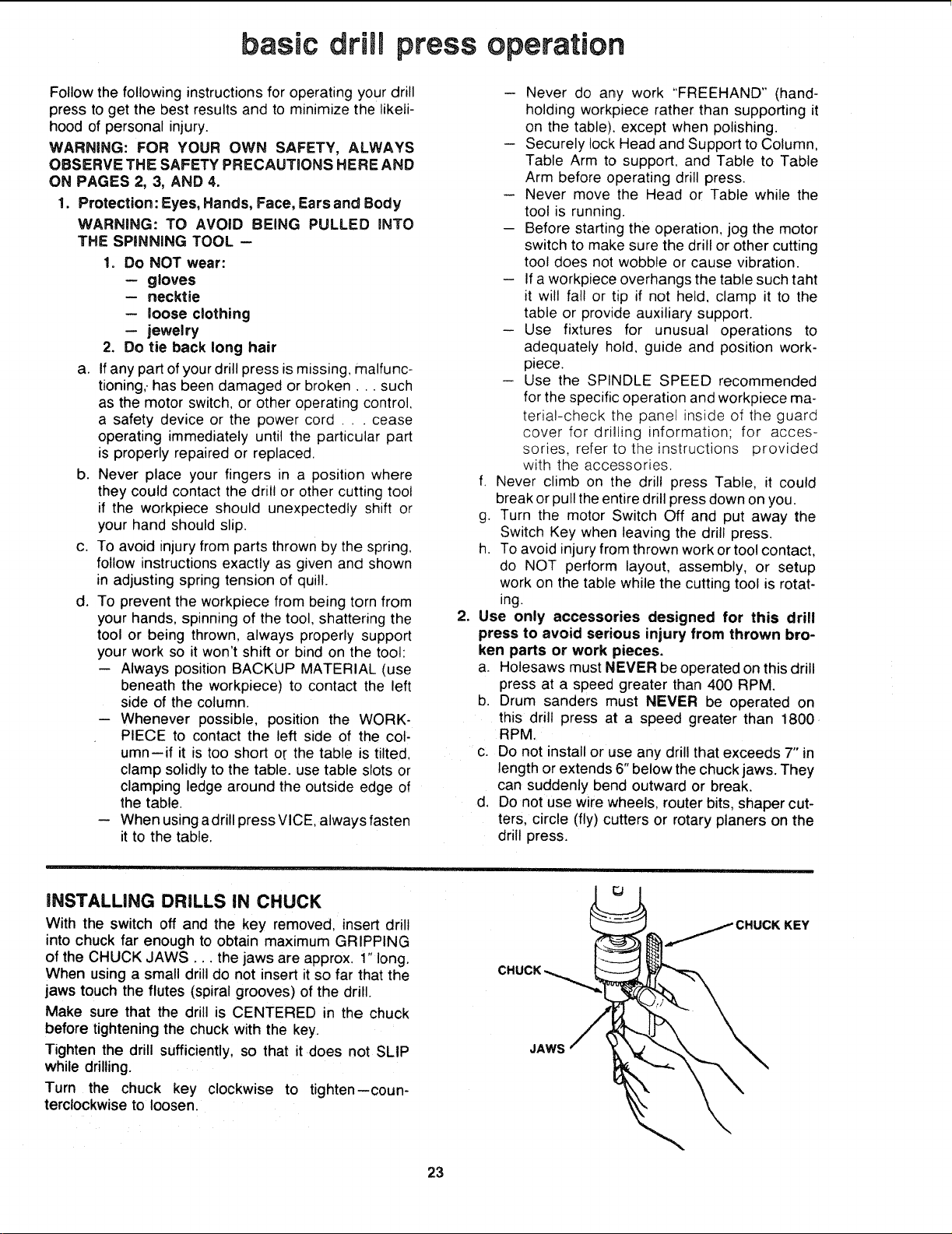
|NSTALLING DRILLS IN CHUCK
With the switch off and the key removed, insert drill
into chuck far enough to obtain maximum GRIPPING
of the CHUCK JAWS... the jaws are approx. 1" long.
When using a small drill do not insert it so far that the
jaws touch the flutes (spiral grooves) of the drill.
Make sure that the drill is CENTERED in the chuck
before tightening the chuck with the key.
Tighten the drill sufficiently, so that it does not SLiP
while drilling.
Turn the chuck key clockwise to tighten--coun-
terclockwise to loosen.
JAWS
KEY
23

POSiTIONiNG TABLE AND WORKPIECE
Lock the table to the column in a position so that the
tip of the drill isjust a littleabove the top of the work-
piece.
Always place a piece of BACK-UP MATERIAL (wood.
plywood..) on the table underneath the workpiece.
This will prevent "splintering" or making a heavy burr
on the underside of the workpiece as the drillbreaks
through. To keep the backup material from spinning
outof control, it must contact the left side of the column,
as illustrated.
WARNING: TO PREVENT THE WORKPIECE OR THE
BACKUP MATERIAL FROM BEING TORN FROM
YOUR HAND WHILE DRILLING, POSITION THEI_/I
AGAINST THE LEFT SIDE OF THE COLUMN. iF THE
WORKPICE OR THE BACKUP MATERIAL ARE NOT
LONG ENOUGH TO REACH THE COLUMN, CLAMP
THEM TO THE TABLE. FAILURE TO DO THiS
COULD RESULT iN PERSONAL INJURY.
WORKPIECE
MATERIAL
For small pieces that cannot be clamped to the table,
use a drill press vise (Optional accessory.)
WARNING: THE VISE MUST BE CLAMPED OR
BOLTED TO THE TABLE TO AVOID iNJURY FROM
SPINNING WORK AND ViSE OR TOOL BREAKAGE.
WORKPIECE
DRILL PRESS
VISE
BOLT OR CLAMP
VICE SECURELY
24
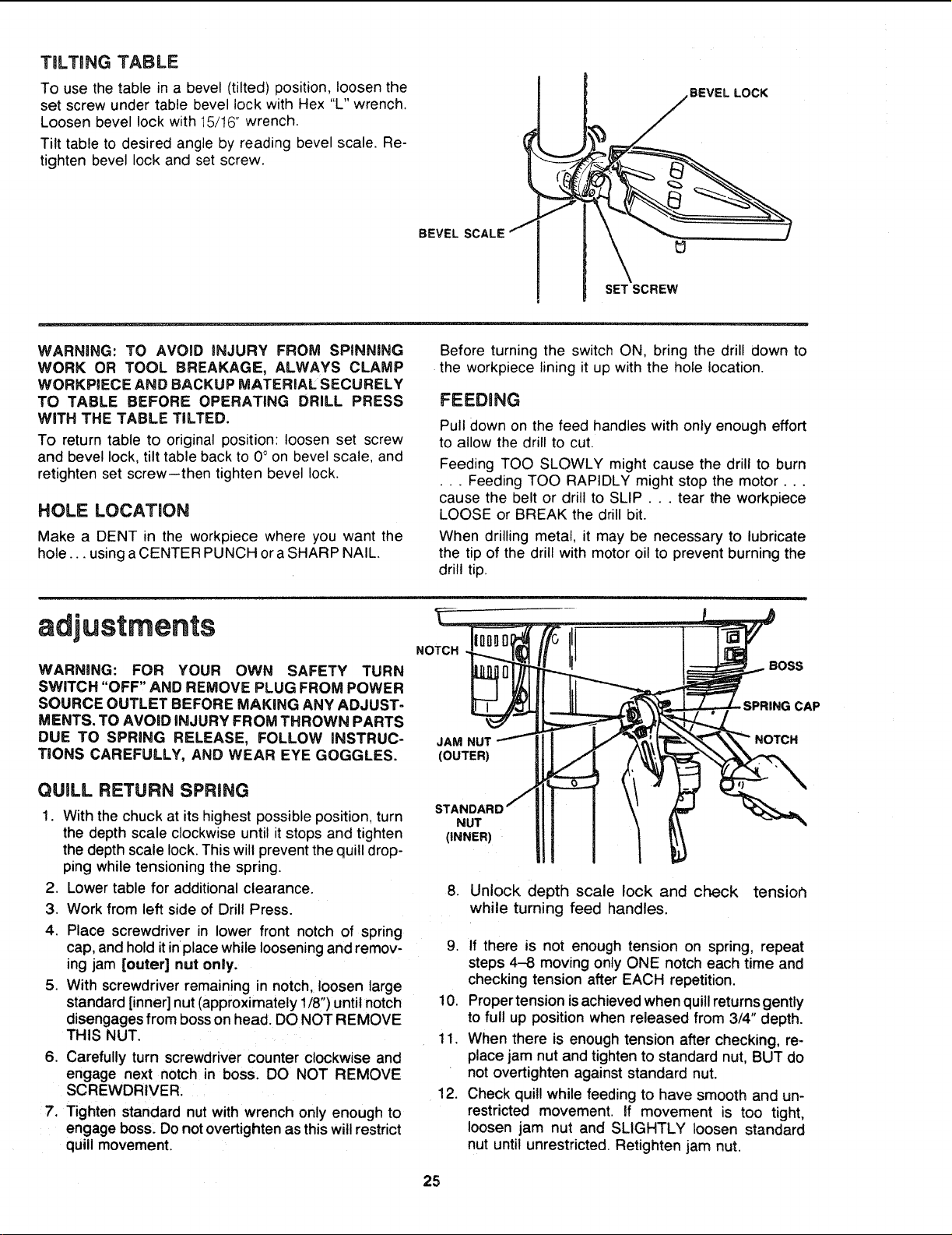
TiLTiNG TABLE
To use the table in a bevel (tilted) position, loosen the
set screw under table bevel lock with Hex "L" wrench.
Loosen bevel lock with 15/t6" wrench.
Tilt table to desired angle by reading bevel scale. Re-
tighten bevel lock and set screw.
BEVEL SCALE
SET SCREW
BEVEL LOCK
WARNING: TO AVOmD INJURY FROM SPINNING
WORK OR TOOL BREAKAGE, ALWAYS CLAMP
WORKPIECE AND BACKUP MATERIAL SECURELY
TO TABLE BEFORE OPERATING DRILL PRESS
WiTH THE TABLE TILTED.
To return table to original position: loosen set screw
and bevel lock, tilt table back to 0 ° on bevel scale, and
retighten set screw--then tighten bevel lock.
HOLE LOCATION
Make a DENT in the workpiece where you want the
hole.., using a CENTER PUNCH or a SHARP NAIL.
Before turning the switch ON, bring the drill down to
the workpiece lining it up with the hole location.
FEEDBNG
Pull down on the feed handles with only enough effort
to allow the drill to cut.
Feeding TOO SLOWLY might cause the drill to burn
• . . Feeding TOO RAPIDLY might stop the motor...
cause the belt or drill to SLIP... tear the workpiece
LOOSE or BREAK the drill bit.
When drilling metal, it may be necessary to lubricate
the tip of the drill with motor oil to prevent burning the
drill tip•
adjustments
WARNING: FOR YOUR OWN SAFETY TURN
SWITCH "OFF" AND REMOVE PLUG FROM POWER
SOURCE OUTLET BEFORE MAKING ANY ADJUST-
MENTS. TO AVOID iNJURY FROM THROWN PARTS
DUE TO SPRING RELEASE, FOLLOW iNSTRUC-
TiONS CAREFULLY, AND WEAR EYE GOGGLES.
NOTCH
JAM NUT
(OUTER)
BOSS
- SPRING CAP
NOTCH
QUILL RETURN SPRING
1. With the chuck at its highest possible position, turn
the depth scale clockwise until it stops and tighten
the depth scale lock. This will prevent the quill drop-
ping while tensioning the spring•
2. Lower table for additional clearance.
3. Work from left side of Drill Press.
4. Place screwdriver in lower front notch of spring
cap, and hold itinplace while loosening and remov-
ing jam [outer] nut only.
5. With screwdriver remaining in notch, loosen large
standard [inner] nut (approximately 1/8") until notch
disengages from boss on head. DO NOT REMOVE
THIS NUT.
6. Carefully turn screwdriver counter clockwise and
engage next notch in boss. DO NOT REMOVE
SCREWDRIVER.
7. Tighten standard nut with wrench only enough to
engage boss. Do not overtighten as this will restrict
quill movement.
STANDAR
NUT
(iNNER)
8. Unlock depth scale lock and check tensior_
while turning feed handles.
9. If there is not enough tension on spring, repeat
steps 4-8 moving only ONE notch each time and
checking tension after EACH repetition.
10. Proper tension is achieved when quill returns gently
to full up position when released from 3/4" depth.
11. When there is enough tension after checking, re-
place jam nut and tighten to standard nut, BUT do
not overtighten against standard nut.
12. Check quill while feeding to have smooth and un-
restricted movement. If movement is too tight,
loosen jam nut and SLIGHTLY loosen standard
nut until unrestricted. Retighten jam nut.
25

SOURCE OUTLET BEFORE MAINTAINING OR LUB-
RICATING YOUR DRILL PRESS.
Frequently blow out any dust that may accumulate in-
side the motor.
A coat of automobile-type paste wax when applied
to the table and column will help to keep tlqe sur-
faces clean.
WARNING: TO AVOID SHOCK OR FIRE HAZARD,
IF THE POWER CORD IS WORN OR CUT, OR DAM-
AGED IN ANY WAY, HAVE IT REPLACED iM-
MEDIATELY.
lubrication
All of the BALL BEARINGS are packed with grease at
the factory. They requtre no further lubrication.
Periodically lubricate the gear and rack. table elevation
mechanism, the SPLINES (grooves) in the spindle, and
the RACK (teeth of the quill). See "Getting to Know
Your Drill Press"
WHITE I WIRE
WHITE CONN BLACK JUMPER
LIGHT BLACK
WIRING DIAGRAM
recommended accessories
WARNING: USE ONLY RECOMMENDED ACCES-
SORIES. FOLLOW iNSTRUCTIONS THAT ACCOM-
PANY ACCESSORIES. USE OF IMPROPER ACCES-
SORIES MAY CAUSE HAZARDS.
Drill Bits ........................ See Catalog Sanding Drums ................ 9-2497 -- 9-2498
Hold-Down and Guide ................. 9-2457 Buffing Wheels up to 4" dia. max ..... See Catalog
Drill Press Vises ................... See Catalog Polishing Wheel, 1 1/2" x 1". ............ 9-64991
Rotary Table ......................... 9-2495 Power Tool Know-How Handbooks
Drill Press Mortising Kit ................ 9-29506 Radial Saw ....................... 9-2917
Hole Saw up to 2 1/2" dia. max....... See Catalog Table Saw ........................ 9-2918
5 pc. Stop Collar Set .................. 9-67063
The recommended accessories listed here
are current and were available at the time
this manual was printed.
26
troubJe shooting
WARNING: FOR YOUR OWN SAFETY, TURN SWITCH "OFF" AND ALWAYS REMOVE PLUG FROM POWER
SOURCE OUTLET BEFORE TROUBLE SHOOTING.
® CONSULT YOUR LOCAL SEARS SERVICE CENTER IF FOR ANY REASON MOTOR WILL NOT RUN.
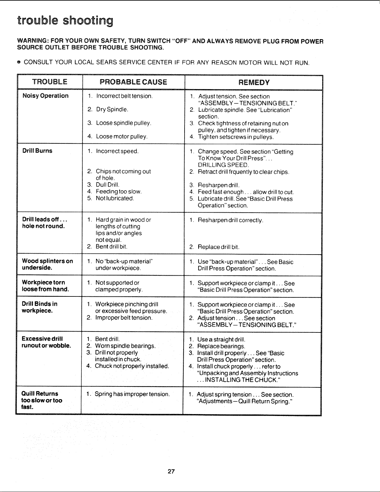
TROUBLE
i
Noisy Operation
Drill Burns
Drill toads off...
hole not round.
PROBABLE CAUSE
1. Incorrect belt tension.
2. Dry Spindle.
3. Loose spindle pulley.
4. Loose motor pulley.
1. Incorrect speed.
2. Chips not coming out
of hole.
3. Dull Drill.
4. Feeding too slow.
5. Not lubricated.
1. Hard grain in wood or
lengths of cutting
lips and/or angles
notequal.
2. Bent drill bit.
.
REMEDY
1. Adjust tension, See section
"ASSEMBLY-TENSIONING BELT."
2. Lubricate spindle, See "Lubrication"
section,
3. Check tightness of retaining nut on
pulley, and tighten if necessary.
4, Tighten setscrews in pulleys.
1. Change speed. See section "Getting
To Know Your Drill Press"...
DRILLING SPEED.
Retract drill frquently to clear chips.
-3. Resharpen drill.
4. Feed fast enough.., allow drill to cut.
5, Lubricate drill. See "Basic Drill Press
Operation" section.
1, Resharpen drill correctly.
,
1.
Replace drill bit.
Wood splinters on 1. No "back-up material" Use "back-up material"... See Basic
underside, underworkpiece. Drill Press Operation" section.
Workpiece torn 1. Not supported or 1. Support workpiece or clamp it... See
loose from hand. clamped properly. "Basic Drill Press Operation" section.
Drill Binds in
workpiece.
1, Support workpiece or clamp it... See
"Basic Drill Press Operation" section.
2. Adjust tension, .. See section
"ASSEMBLY-TENSIONING BELT."
Excessive drill
runout or wobble.
1. Workpiece pinching drill
or excessive feed pressure.
2. Improper belt tension.
1. Bent drill.
2. Worn spindle bearings.
3. Drill not properly
installed in chuck.
4. Chuck not properly installed.
1, Spring hasimpropertension.
Quill Returns
too slow or too
fast.
1. Use a straight drill.
2. Replace bearings.
3. Install drill properly.,. See "Basic
Drill Press Operation" section.
4. Install chuck properly.., referto
"Unpacking and Assembly Instructions
•.. INSTALLING THE CHUCK."
1.
Adjust spring tension... See section.
"Adjustments--Quill Return Spring."
27
I
6
/
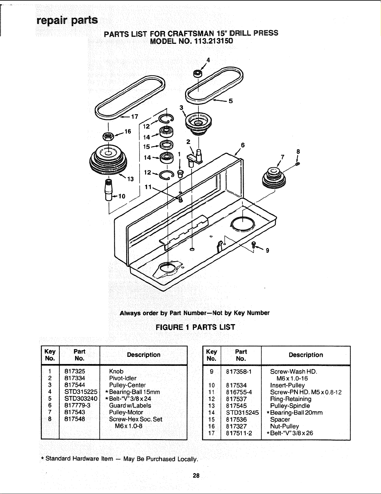
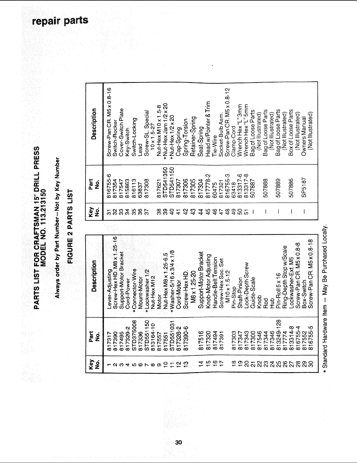
Always order by Part Number--Not by Key Number
FIGURE 1 PARTS LIST
Key
Dart
",,.'" , Description
No. ,lu.u.
1
2
3
4
5
6
7
8
817325
817334
817544
STD315225
STD303240
817779-3
817543
817548
Knob
Pivot-Idler
Pulley-Center
* Bearing-Ball 15mm
* Belt-"V" 3/8 x 24
Guard w/Labels
Pulley-Motor
Screw-Hex Soc. Set
M6x 1.0-8
Key Part
No. No.
9 817358-1
10 817534
11 816755-4
12 817537
13 817545
14 STD315245
15 817536
16 817327
17 817511-2
Description
Screw-Wash HD.
M6x1.0-16
insert-Pulley
Screw-PN HD. M5 x0.8-12
Ring-Retaining
Pulley-Spindle
* Bearing-Ball 20mm
Spacer
Nut-Pulley
* Belt-"V" 3/8 x 26
* Standard Hardware Item -- May Be Purchased Locally,
28

repair parts
o_
\
Lf_
LU
G.
-J
-J
G:
T" 03
Zo_
¢/)T-
_d
_z
G:.j
(.,)w
G:C3
0 o
.J
T "¸
,€_J
f
/
T--
_N
N
/
o
o'J
\
cD
€_
€_
/
W
o
€_
_Q
repair parts
r"
0
,m
om
b
oO
ua
d
OL
ooo
×o_
O9 no
o
o
_J
o
o
O-
rn
I
E
o
I
€-
O9
-I=
3O

repair parts
PARTS LgST FOR CRAFTSMAN 15" DRfLL pF_ESS
MODEL NO. 113.213150
11
10
89
I
'4.
",J
2
.F..I _6
7
Always order by Part Number--Not by Key Number
FIGURE 3 PARTS LIST
Key PaN
No. No.
I 817309
2 817310
3 817311
4 STD315235
5 817535
6 817532
Description
Locknut M!7 x 1.0
Ring-Locking
Washer
* Bearing-Ball 17mm
Gasket-Quill
Tube-Quill
* Standard Hardware Item -- May Be Purchased Locally.
Key Part
No. No.
7 817326
8 817339
9 817340
10 817341
11 817531
i ,,
Description
Key-Drift
Key-Chuck
Chuck
Arbor
Spindle
31
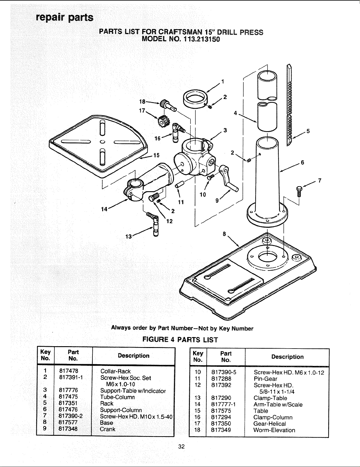
PARTS LiST F R "
O CRAFTSMAN 15 DRILL PRESS
MODEL NO. 113.213150
12
\
Key
No.
1
2
3
4
Always order by Part Number--Not by Key Number
FIGURE 4 PARTS LiST
Part
No.
817478
817391-1
817776
817475
Description
Collar-Rack
Screw-Hex Soc. Set
M6x1,0-10
Support-Table w/indicator
Tube-Column
Key Part
No. No.
10 817390-5
11 817288
12 817392
13 817290
14 817777-1
15 817575
16 817294
17 817350
18 i 817349
Description
Screw-Hex HD. M6x 1.0-12
Pin-Gear
Screw-Hex HD.
5/8-11 x 1-1/4
Clamp-Table
Arm-Table w/Scale
Table
Clamp-Column
Gear-Helical
Worm-Elevation
32

33

Notes:
34

Notes:
35
f
SERVHCE
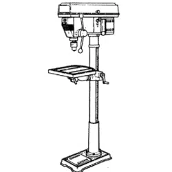
MODEL NO.
113.213150
DRILL PRESS WITH
MAXIMUM
DEVELOPED
I HP MOTOR
HOW TO ORDER
REPAIR PARTS
Now that you have purchased your 15-inch Drill Press, should
a need ever exist for repair parts or service, simply contact
any Sears Service Center and most Sears, Roebuck and Co.
store_ Be sure to provide all pertinent facts when you call
or visit.
The model number of your 15-inch Drill Press will be found
on a plate attached to the rear of the head.
WHEN ORDERING REPAIRPARTS,ALWAYS GIVE THE FOLLOWING
INFORMATION:
PARTNUMBER PARTDESCRIPTION
MODEL NUMBER
113213150
NAME OF ITEM
MOTORIZED 15-INCH
FLOOR MODEL DRILLPRESS
All parts listed may be ordered from any Sears Service Center
and most Sears stores. If the parts you need are not stocked
locally, your order will be electronically transmitted to a Sears
Repair Parts Distribution Center for handling.
Sold by SEARS,
Part No. SP5187
ROEBUCK AND CO., Chicago, IL 60684 U.S.A.
Form No. SP5187-4 Printed in Taiwan
2/92