Loading ...
Loading ...
Loading ...
14
Bearings - Disassemble motor as per section F-3.1.
Remove snap ring (6) with snap ring pliers and pull motor
(1) and lower bearing (4) straight off of seal plate (2).
Inspect all parts for signs of wear and replace as needed.
CAUTION! Handle seal parts with extreme care.
do not scratch or mar lapped surfaces.
F-3.2) Replacing Bearing:
When replacing bearing, be careful to not damage the
rotor or shaft threads. Press the old bearing off the
shaft with an arbor press or gear puller. Clean the shaft
thoroughly. Apply adhesive compound to shaft and press
new bearing on, pushing only on the inner race, until it
seats against shoulder of shaft (see fi g.12).
IMPORTANT! - All parts must be clean before
reassembly.
F-3.3) Reassembly:
Make sure shaft seal (3) is clean and in proper position as
per section F-4.2 before reassembling rotor and bearing.
Slide lower bearing and rotor shaft squarely into the seal
plate (2) until bearing seats on the bottom. Insert snap
ring (6) into seal plate with fl at edge against outer race of
bearing. Place motor stator squarely onto seal plate (2)
and tighten motor screws. Install o-ring (13) onto seal plate
(2).
On BP & SE Series, slip motor wires through opening in
motor housing (14) see Figure 5. Connect motor wires to
cord set as per Figure 7. Place friction ring (9b) and gland
nut (9a) into motor housing (14) and tighten gland nut to
17.5 ft. lbs. On “AU” series pumps slip fl oat wires through
opening in motor housing (14) and connect to fl oat cable
(29) see Figure 8. Place friction ring (29b) and gland nut
(29a) into motor housing (14) and tighten gland nut to 17.5
ft. lbs.
Place motor housing (14) squarely onto seal plate (2).
Tighten socket head screws (15) into motor housing. Refi ll
with cooling oil as per paragraph F-1.3.
On BP-HT & SE-HT Series, slide the gland nut, friction
rings and grommet onto cord set (see Figure 6) and slip
cord through motor housing (14). Connect motor wires
per Figure 9. Place motor housing (14) squarely onto
seal plate while pulling excess cord through hole. Tighten
socket head screws (15) into motor housing. Slide the
friction rings (9b), grommet (9c) and gland nut (9a) into
motor housing and tighten gland nut to 17.5 ft. lbs. Refi ll
with cooling oil as per paragraph F-1.3. On “HTAU” series
pumps slide the gland nut, friction rings and grommet onto
cord set (see Figure 6) and slip cord (29) through motor
housing (14). Connect wires per Figure 10.
F-4) Shaft Seal Service
F-4.1) Dissassembly and Inspection:
Disassemble pump motor as per section F-3.1. Inspect
seal for signs of wear such as uneven wear pattern on
the stationary member or chips and scratches on either
sealing face. Do not interchange seal components.
Replace entire seal if damage occurs.
F-4.2) Replacing Shaft Seal (refer to fi g. 11, 12 & 13):
When replacing the shaft seal (3), remove used rotating
member (3c), spring (3b), and spring retainer (3a) from
motor shaft. Press used stationary member (3d) from the
seal plate (2). At reassembly, clean seal cavity thoroughly
and apply a light coat of oil. Lightly oil the rubber ring (DO
NOT use grease) and press the stationary member fi rmly
into the seal plate using a seal pusher (See Parts List-
Seal Tool Kit), nothing but pusher to come in contact with
seal face (see Fig. 11). Insert so that the fi nished surface
is up and the grooved surface is against the seal plate.
Make sure the stationary member is in straight and that the
rubber ring is not out of it’s groove.
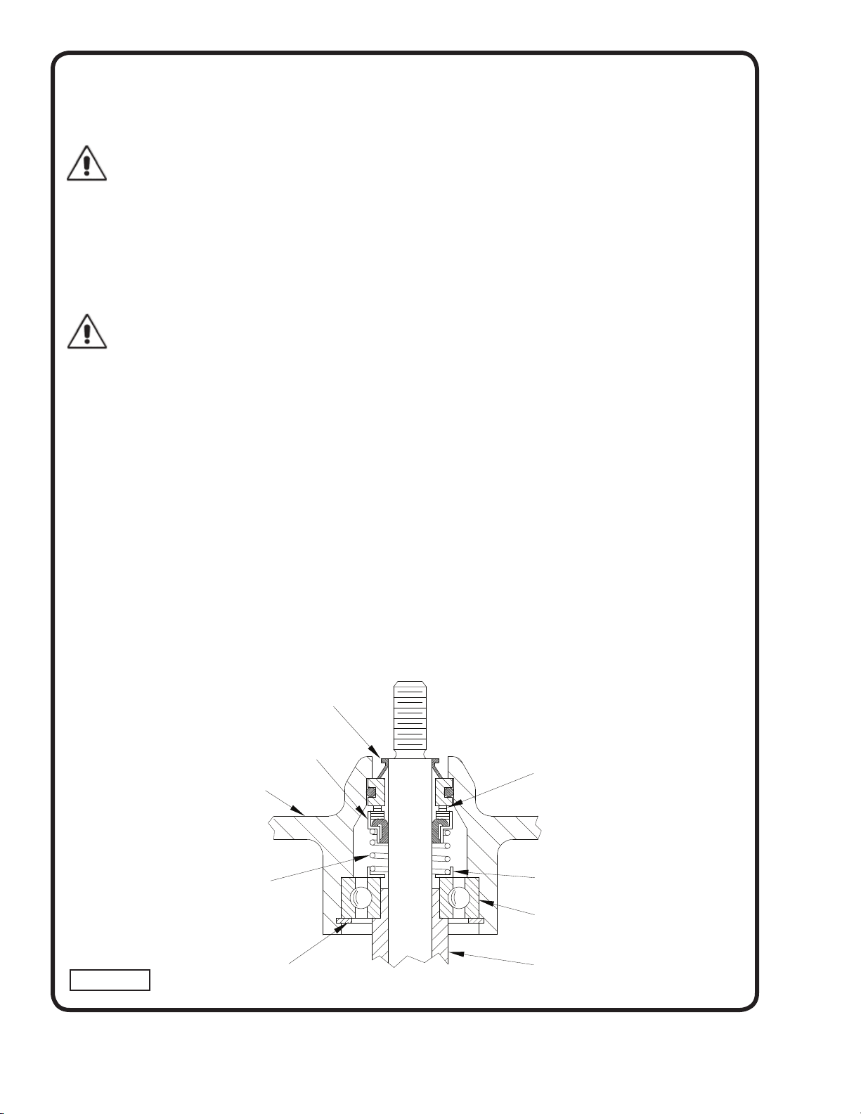
Exclusion Seal
Bearing (4)
Seal Plate
Spring (3b)
Retaining Ring (6)
Stationary (3d)
Polished Mating Surface
Rotating Member (3c)
Sleeve (27)
MOTOR END
(Inboard End)
PUMP END
(Outboard End)
FIGURE 12
Retaining Ring (3a)
Loading ...
Loading ...
Loading ...