Installation Plan
Washing Machine
PW 811
PW 814
PW 818
To prevent accidents and machine damage, read
these instructions before installation or use.
en-US
M.-Nr. 10 668 670

Contents
2
Installation and planning notes..........................................................................................4
Installation requirements ....................................................................................................... 4
Storage/Transportation.......................................................................................................... 4
General operating conditions ................................................................................................ 4
Installation ............................................................................................................................. 5
Installation on concrete base ........................................................................................... 5
Leveling the machine............................................................................................................. 6
Securing the machine............................................................................................................ 6
Installation of steam-heated washing machines ................................................................... 7
Steam connection valve ................................................................................................... 7
Condensate trap............................................................................................................... 7
Heater bank information................................................................................................... 8
Fitting information for steam and condensate hoses....................................................... 8
Machine connections ............................................................................................................ 9
Electrical connection ........................................................................................................... 10
Water connection ................................................................................................................ 12
Cold water connection ................................................................................................... 12
Hot water connection ..................................................................................................... 12
Drain valve ...................................................................................................................... 12
Dispenser pump connections ............................................................................................. 14
Optional accessories........................................................................................................... 15
XKM RS232 communication module ............................................................................. 15
Base ............................................................................................................................... 15
Weighing base................................................................................................................ 15
Suds drain and vapor vent (BWS) .................................................................................. 15
Technical drawings - dimensions in inches ....................................................................16
PW811................................................................................................................................ 16
Dimensions..................................................................................................................... 16
Dimensions with Mielebase (UG/UO)/weighting base (WI) ........................................... 17
Installation ...................................................................................................................... 18
PW814................................................................................................................................ 19
Dimensions..................................................................................................................... 19
Dimensions with Mielebase (UG/UO)/weighting base (WI) ........................................... 20
Installation ...................................................................................................................... 21
PW818................................................................................................................................ 22
Dimensions..................................................................................................................... 22
Dimensions with Mielebase (UG/UO)/weighting base (WI) ........................................... 23
Installation ...................................................................................................................... 24
Anchoring PW811/814/818 ................................................................................................ 25
Attaching to the floor/concrete base.............................................................................. 25
Attaching to the floor/concrete base when installing in a run ........................................ 25
Attaching to the floor with Mielebase............................................................................ 26
Technical drawings - dimension in millimeters ..............................................................27
PW811................................................................................................................................ 27
Dimensions..................................................................................................................... 27
Dimensions with Mielebase (UG/UO)/weighting base (WI) ........................................... 28
Installation ...................................................................................................................... 29

Contents
3
PW814................................................................................................................................ 30
Dimensions..................................................................................................................... 30
Dimensions with Mielebase (UG/UO)/weighting base (WI) ........................................... 31
Installation ...................................................................................................................... 32
PW818................................................................................................................................ 33
Dimensions..................................................................................................................... 33
Dimensions with Mielebase (UG/UO)/weighting base (WI) ........................................... 34
Installation ...................................................................................................................... 35
Anchoring PW811/814/818 ................................................................................................ 36
Attaching to the floor/concrete base.............................................................................. 36
Attaching to the floor/concrete base when installing in a run ........................................ 36
Attaching to the floor with Miele base............................................................................ 37
Technical data....................................................................................................................38
Water connection ................................................................................................................ 38
Models with detergent dispenser drawer (WEK) ............................................................ 38
Drain valve ...................................................................................................................... 38
Optional steam valves for steam-heated models................................................................ 38
Electric steam valve (ELD01)......................................................................................... 38
Pneumatic steam valve (PND) ........................................................................................ 38
Connection for equipotential bonding................................................................................. 38
Anchoring ............................................................................................................................ 39
Attaching to the floor...................................................................................................... 39
Attaching to the floor with Miele base............................................................................ 39
Attaching to a concrete base (provided on-site) ............................................................ 39
PW811................................................................................................................................ 40
Electrical version and electrical data.............................................................................. 40
Installation dimensions................................................................................................... 40
Transport data, weight and floor load ............................................................................ 41
Emissions data ............................................................................................................... 41
PW814................................................................................................................................ 42
Electrical version and electrical data.............................................................................. 42
Installation dimensions................................................................................................... 43
Transport data, weight and floor load ............................................................................ 43
Emissions data ............................................................................................................... 43
PW818................................................................................................................................ 44
Electrical version and electrical data.............................................................................. 44
Installation dimensions................................................................................................... 45
Transport data, weight and floor load ............................................................................ 45
Emissions data ............................................................................................................... 45

Installation and planning notes
4 PW 811 / PW 814 / PW 818
Installation requirements
The washing machine must be installed by Miele Service or by
properly trained staff of an authorized dealer.
This washing machine must be installed in accordance with all rel-
evant regulations and standards. Local energy supplier regulations
must also be observed.
This washing machine must only be operated in a room that has
sufficient ventilation and which is frost-free.
The washing machine should not be installed or operated in any
area where there is a risk of explosion.
Storage/Transportation
The following conditions must be observed for transport and storage
of the machine:
– Ambient temperature: 32-105°F (0-40°C)
– Humidity: non-condensing
General operating conditions
This washing machine is intended only for use in an industrial envi-
ronment and must only be operated indoors.
– Ambient temperature of location: 32-105°F (0-40°C)
– Relative humidity: non-condensing
– Maximum height above sea level of location site: 6500 ft (2000 m)
Depending on the nature of the installation site, sound emissions and
vibration may occur.
Tip: Have the installation site inspected and seek the advice of a pro-
fessional in instances where increased noise may cause a nuisance.

Installation and planning notes
PW 811 / PW 814 / PW 818 5
Installation
This washing machine must be transported to its installation site us-
ing a suitable pallet jack. Remove the transport packaging.
The washing machine must be set up on a level and firm surface with
the minimum stated load bearing capacity (see "Technical data").
The floor load created by the washing machine is concentrated and
transferred to the installation footprint via the machine feet.
Tip: A concrete floor is the most suitable installation surface for this
machine, being far less prone to vibration during the spin cycle than
wooden floorboards or a carpeted surface.
The washing machine requires a gap of at least 2" (50mm) on each
side to allow for movement during operation. To ensure suitable ac-
cess for further maintenance and service work, please ensure a mini-
mum distance of 16" (400mm) is maintained between the back of the
machine and the wall.
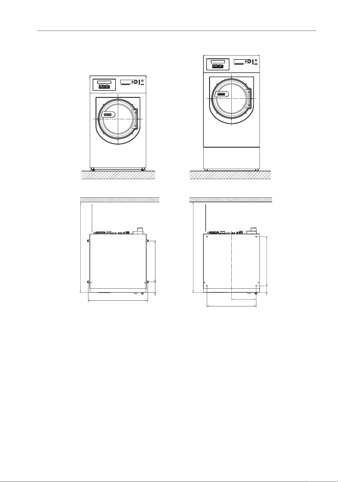
Installation on
concrete base
The washing machine can be installed on a concrete base if desired.
The concrete materials and the durability of the concrete base must
be assessed in accordance with the floor load bearing capacity
given in "Technical data".
To guarantee the stability of the washing machine, make sure that
the concrete base is sufficiently stable on the floor and that it is ca-
pable of withstanding any burden or force from the washing ma-
chine.
The washing machine must be secured to the concrete base using
the fixtures and fastenings supplied.
The washing machine must be secured to the base immediately
after installation!
There is a risk of the washing machine falling off a raised base dur-
ing a spin cycle if it is not secured.

Installation and planning notes
6 PW 811 / PW 814 / PW 818
Leveling the machine
Align the washing machine vertically and horizontally using the ad-
justable feet and a spirit level.
The washing machine must stand perfectly level on all four feet to
ensure safe and proper operation. Otherwise water and energy con-
sumption will be increased and the machine could move.
After aligning the machine tighten the lock nuts by turning them in a
counterclockwise direction with a wrench. This will prevent the feet
from moving.
Securing the machine
The feet of the washing machine must be secured to the concrete
base using the fixtures and fastenings supplied.
Fittings supplied are for installation on a concrete floor. For other
types of flooring please purchase suitable fitting materials sepa-
rately.
Installation and planning notes
PW 811 / PW 814 / PW 818 7
Installation of steam-heated washing machines
The steam connection must only be carried out by a registered
installer. During connection please observe the installation instruc-
tions, the data plate on the washing machine, the wiring diagram,
the installation diagram and the documentation supplied.
Steam-heated washing machines must in all cases be secured to
the floor!
Steam connection
valve
Before connecting a steam-heated machine, ensure that the steam
inlet valve, the dirt filter and the steam shut-off valve have been cor-
rectly installed on site.
Steam valves are available from Miele service.
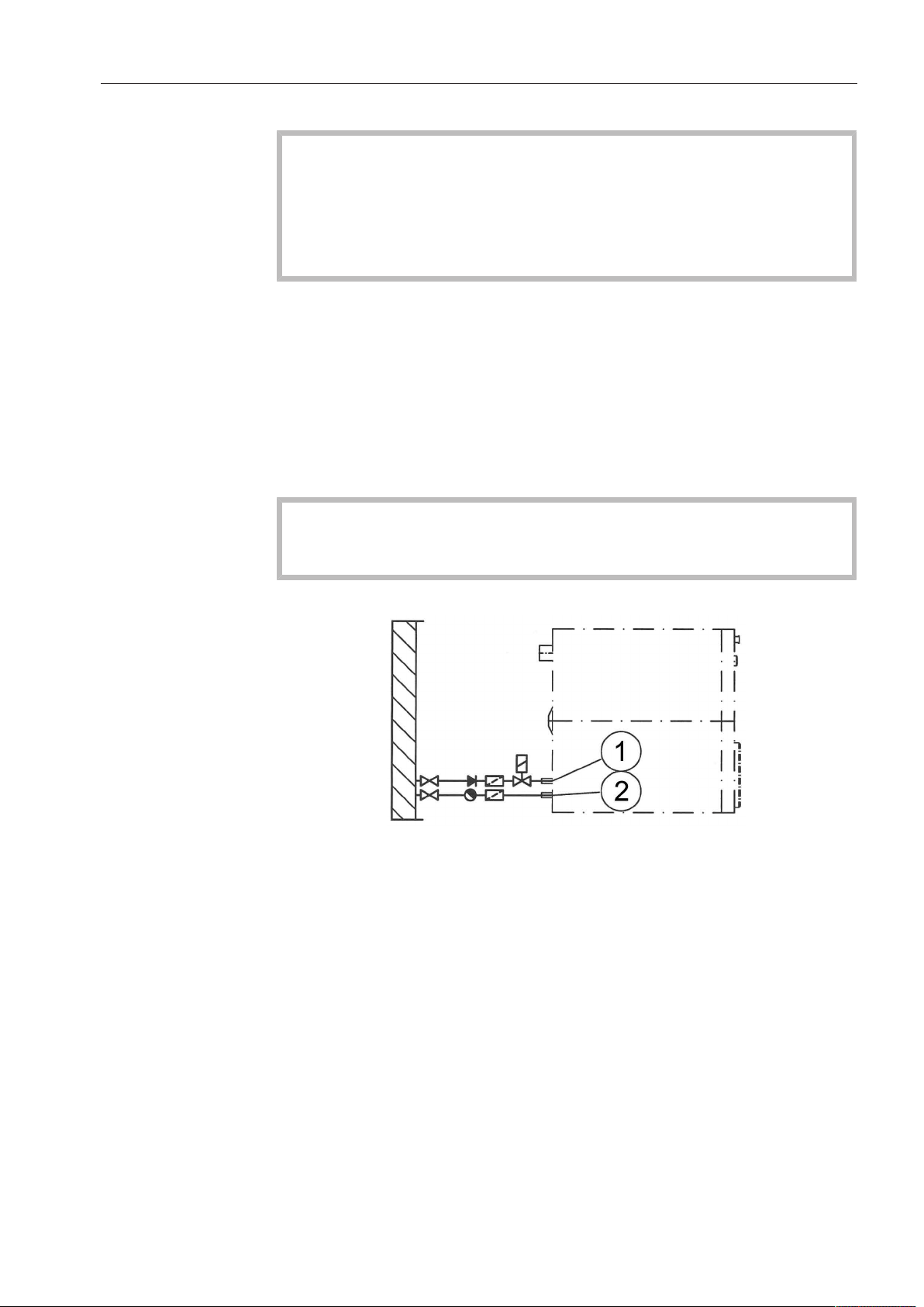
Condensate trap
With steam-heated washing machines a condensate trap is required
for the condensate drain. The condensate trap ensures that conden-
sate is completely drained away from the washing machine heater
bank.
The condensate trap must be installed in such a way that conden-
sate cannot get back into the heater bank when the machine is not
in operation.
Tip: Use a bell condensate trap for the condensate drain.
a
Steam valve
b
Condensate trap

Installation and planning notes
8 PW 811 / PW 814 / PW 818
Heater bank infor-
mation
To avoid damage to the heater bank the following must be observed
during commissioning:
– In order to avoid unnecessary heat variations, ensure that heating is
even. Do not allow sudden bursts of steam.
– To prevent corrosion, preparation of the water supply is absolutely
essential. In particular, when the machine is not in operation, it
must be ensured that no air or CO
2
can enter the steam system.
– Protect the heater bank from aggressive gases.
– The entire heating system must guarantee that no operating pres-
sure or temperature can arise that is higher than the details given
on the data plate.
– All appropriate regulations, standards and legislation from responsi-
ble authorities and accident prevention associations for heating and
ventilation systems (in particular for the operation of the heat ex-
changer) must be observed.
Fitting informa-
tion for steam and
condensate hoses
Make sure that steam and condensate hoses are not twisted or com-
pressed. Do not use the hoses to compensate for connection tube
misalignments!
Installation and planning notes
PW 811 / PW 814 / PW 818 9
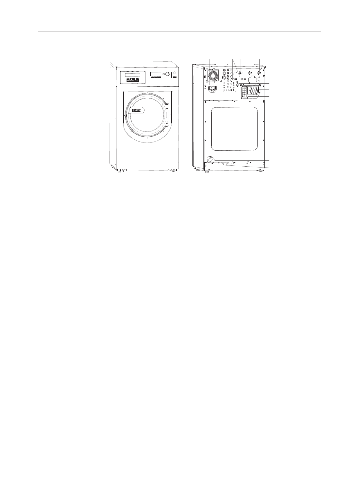
Machine connections
⑥
①
②
③
④
⑤
⑦
⑧
⑨
⑩
⑪
⑫
a
Detergent dispenser (WEK)
b
Communication module slot
The XKMRS232 communication module is available as an optional
accessory.
c
Electrical connection
d
2x hard water connection
(Optional)
e
Cold water connection
f
Hot water connection
Water temperature to maximum 158°F (70°C)
g
Cold water connection
h
Cold water connection for liquid dispensing
(Optional)
i
Connections for external dispenser pumps
For up to 12 dispenser pumps.
j
Vapor extraction/free outlet TypeAB
k
Drain pipe
Connection for plastic pipe NPS2 ¾" (HTDN70).
l
Connection option for direct/indirect steam
(Depending on model)

Installation and planning notes
10 PW 811 / PW 814 / PW 818
Electrical connection
The electrical connection must only be carried out by a qualified
electrician who must ensure that all electrical work is carried out in
accordance with applicable electrical regulations and standards.
The washing machine must be connected to an electrical supply
that complies with local and national regulations. Please also observe
your insurance and energy supplier's regulations as well as any health
and safety at work regulations.
The required voltage, power consumption and specifications for
external fusing are quoted on the data plate on the washing machine.
Ensure that the supply voltage complies with the voltage quoted on
the data plate before connecting the washing machine to the power
supply.
Connection to a supply voltage other than the one quoted on the
data plate can lead to functional faults and damage the washing
machine.
If more than one voltage is quoted on the data plate, the washing
machine can be converted for connection to the voltages stated.
Conversion to a different voltage must only be carried out by a
Miele Service engineer or by an authorized Service Dealer. The wiring
instructions given on the wiring diagram must be followed.
The washing machine can either be hard-wired or connected via a
plug and socket that complies with national codes and regulations.
For a hard-wired connection an all-pole isolation device must be in-
stalled on site.
For hard-wired machines connection should be made via a suitable
switch with all-pole isolation which, when in the off position, ensures
a 1/8" (3 mm) gap between all open contacts. These include circuit
breakers, fuses and relays.
If the power supply cannot be permanently disconnected, the isolator
switch (including plug and socket) must be safeguarded against be-
ing switched on either unintentionally or without authorization.
Tip: We recommend connection to the power supply via a suitable
plug and socket which must be easily accessible for servicing and
maintenance work after the machine has been installed.

Installation and planning notes
PW 811 / PW 814 / PW 818 11
If it is necessary to install a residual current device (RCD) in accor-
dance with local regulations, a residual current device typeB (sensi-
tive to universal current) must be used.
An existing typeA residual current device, (RCD) must be exchanged
for a typeB RCD.
If necessary, equipotential bonding with good galvanic contact
must be guaranteed in compliance with all applicable local and na-
tional installation specifications.
Equipotential bonding must have an earth current rating >10mA.
Accessories for equipotential bonding are not supplied and need to
be ordered separately.

Installation and planning notes
12 PW 811 / PW 814 / PW 818
Water connection
The washing machine complies with current local and national
safety regulations protecting the drinking water supply and can
therefore be connected to the drinking water supply without a non-
return valve.
The machine is designed to operate with a supply pressure of be-
tween 14.5psi (1bar) and must not exceed 145psi (10bar). If it is
highter than 145psi (10bar) a pressure reducing valve must be used.
The machine must be connected to the water supply using the inlet
hoses provided.
The connection points are subject to water supply pressure.
Turn on the faucet slowly and check for leaks.
Correct the position of the seal and union if necessary.
Cold water con-
nection
A supply faucet with ¾" threaded union is required for each connec-
tion to the water supply (single or double). If this is not present, the
washing machine should be connected to the water supply by a qual-
ified plumber.
The inlet hose for cold water (blue stripes) is not intended to be
used with a hot water supply line.
Hot water con-
nection
To minimize energy consumption during operation with hot water,
the washing machine should be connected to a hot water ring cir-
cuit.
So-called "transmission lines" (single lines to hot water generators)
can result in cooling down of the water remaining in the pipes if not
in constant use. More energy would then be consumed to heat the
water up again.
Use the inlet hose supplied (red stripes) for the hot water connection.
The temperature of the water intake must not exceed 158°F (70°C).
If there is no hot water supply at the installation location for the wash-
ing machine, the connection hose must nevertheless be connected to
the cold water supply. A Y-piece is required in this case. The cold wa-
ter consumption increases accordingly to account for the missing hot
water intake.
For functional and technical reasons it is not possible to operate
the machine exclusively with a hot water connection (without a
separate cold water intake).
Even if a hot water connection is present, the washing machine
must be connected to a cold water intake.

Installation and planning notes
PW 811 / PW 814 / PW 818 13
Drain valve
A motorized dump valve is used to drain the machine. A 2¾" angle
connector can be used for draining the machine directly into the
waste water system (without a siphon) or into an on-site gully (with
odor trap). The dump valve can also be operated manually to allow
the suds container to be emptied in the event of a power outage.
A vented drainage system is vital for unimpeded drainage.
If several machines are connected to a single drain pipe, it should
be large enough to allow all machines to drain simultaneously.
The appropriate Mieleinstallation set M.-No.:05238090 is avail-
able from Miele for venting a 2¾"(DN70) pipe.
If the slope for drainage is extremely steep, the piping must be
vented so prevent formation of a vacuum in the machine's drain
system.
Slow or obstructed drainage or a backup of water in the drum as a re-
sult of undersized pipework can result in faults occurring during pro-
grams, which will result in error messages appearing in the display.
Outflowing suds can be as hot as 203°F (95°C). Danger of injury
by burning!
Avoid direct contact.
Installation and planning notes
14 PW 811 / PW 814 / PW 818
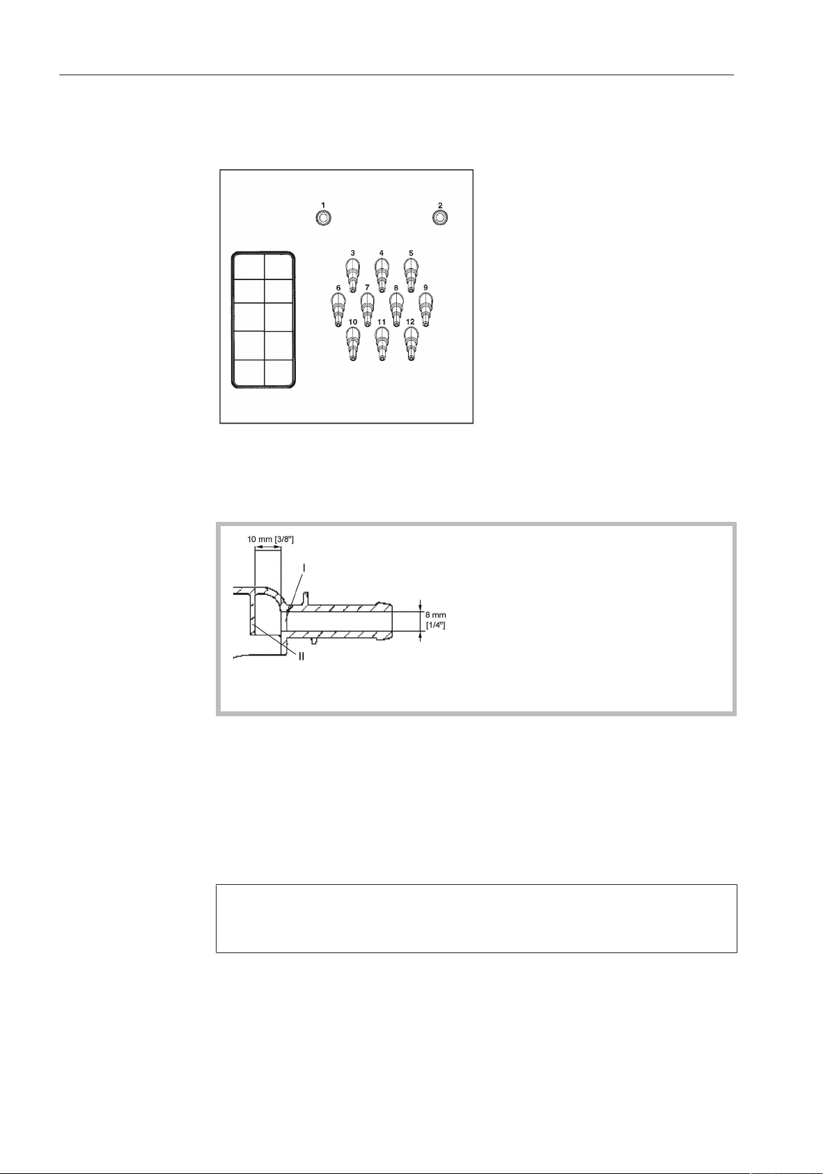
Dispenser pump connections
Up to 12dispenser pumps can be connected to the washing ma-
chine.
Dispenser pump connections on the back of the machine
Connections1 and 2 are for viscous agents. These connectors are
sealed and need to be drilled out before connection with a
5/16" (8mm) drill bit.
Make sure that you only drill through the first panel(I) as there is a
deflecting panel(II) 3/8"(10mm) behind it.
Connections 3 to12 are for liquid dispensing. These connections are
sealed and must be cut to the diameter of the hose with a small saw.
If opened connections are no longer required, they must be resealed
using a suitable sealant (e.g. silicone).
Connection terminals for five time-controlled dispenser pumps, which
can be operated without a multifunction module, are located behind
the cover adjacent to the electrical connection.
Calibration of the dispenser pumps and regulation of dispensing
quantities is carried out automatically for washing machines fitted
with a multifunction module.
A flowmeter or throughput sensors can be connected for precise
monitoring of the dispensing quantity.
Connections for level monitoring are available for every agent dis-
pensed.

Installation and planning notes
PW 811 / PW 814 / PW 818 15
Optional accessories
Only use genuine Miele spare parts and accessories with this ma-
chine.
Using spare parts or accessories from other manufacturers will
void the warranty, and Miele cannot accept liability.
XKM RS232 com-
munication mod-
ule
The serial interface RS-232 can be retrofitted to the washing machine
via an XKMRS232 (optional accessory available from Miele). This
communication module must only be used with MieleProfes-
sionalmachines that are fitted with an appropriate slot for the mod-
ule.
The data interface provided via communication module
XKMRS232 complies with SELV (Safety Extra Low Voltage) in ac-
cordance with EN60950.
Machines connected to this interface must also be SELV compliant.
Communication module XKMRS232 is supplied with a connection
cable and a D-sub-connector.
Base
The machine can be installed on a machine base (open or box base,
available as an optional Miele accessory).
Elevating the washing machine gives a better ergonomic working
position when loading or unloading. It also simplifies the installation
of a waste water connection.
When installed on a raised base, the machine must be secured
to the base and the base must be secured to the floor.
There is a risk of the washing machine falling off a raised base dur-
ing a spin cycle if it is not secured.
Weighing base
The washing machine is optionally available with a weighing base. In
this version, the actual weight of the laundry load is displayed during
loading along with the maximum laundry load weight for the unit.
Make sure that the washing machine is not in contact with objects
or people located nearby or leaning against it. They could be
weighed as well and falsify the load weight shown on the display.
Suds drain and
vapor vent (BWS)
If excessive suds form, suds may escape from the vapor vent. To
drain the suds, an optional vapor vent kit (BWS) can be installed.
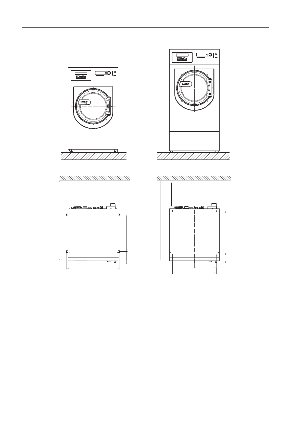
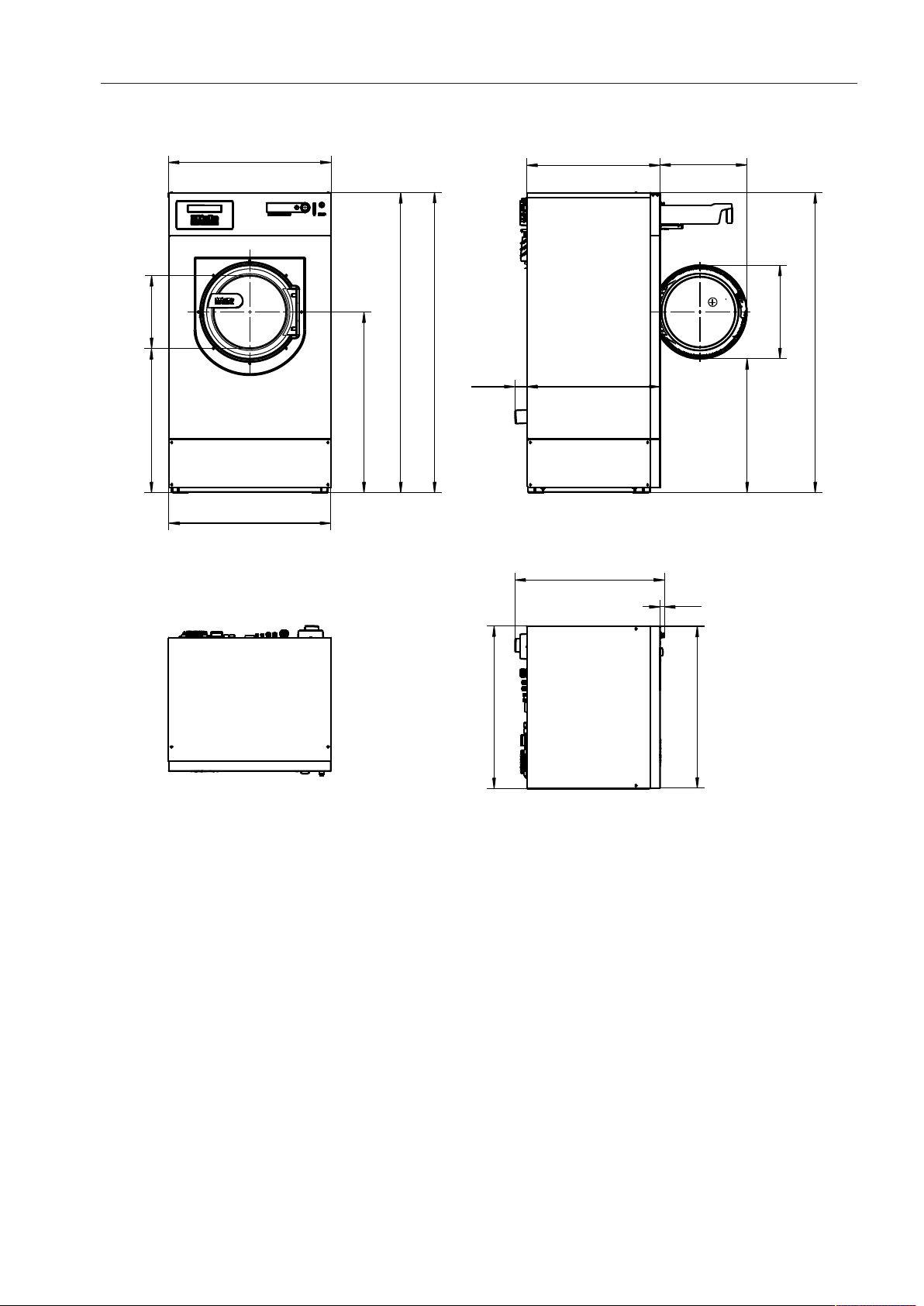
Technical drawings - dimensions in inches
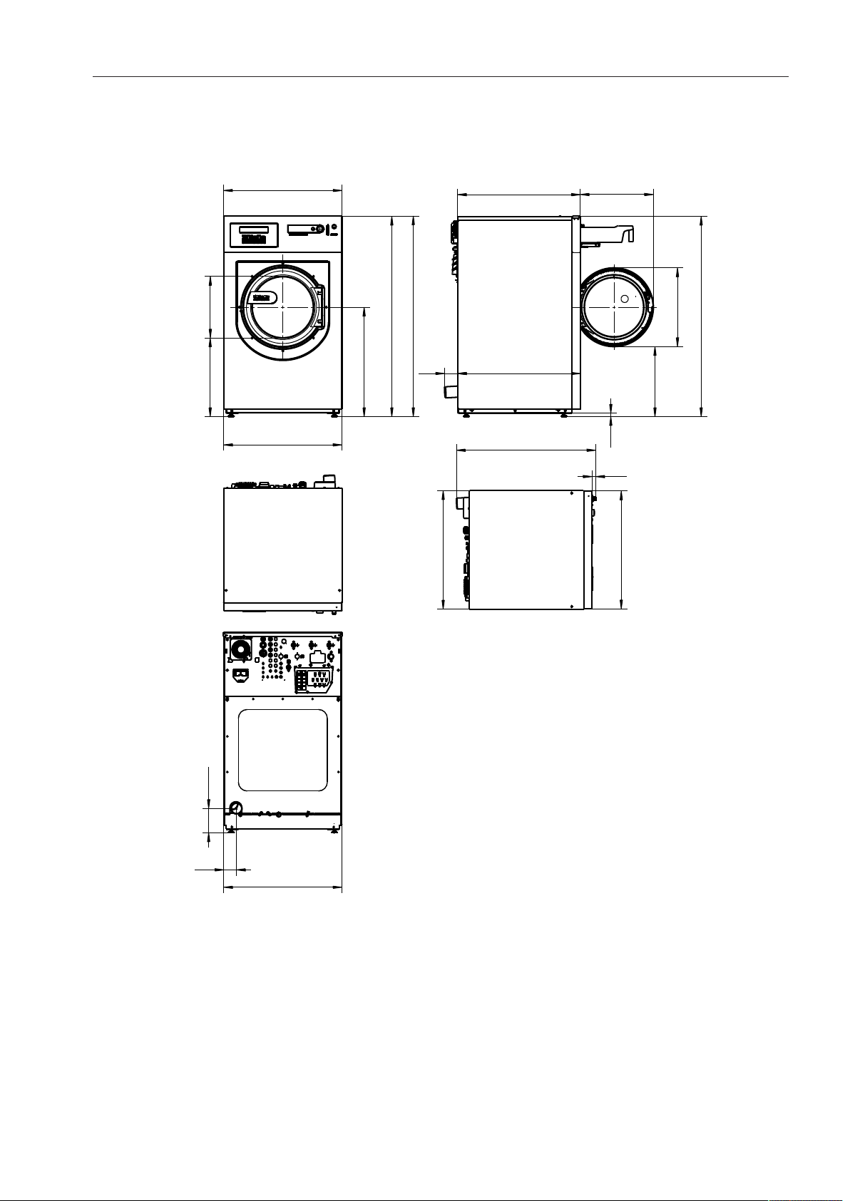
16 PW 811 / PW 814 / PW 818
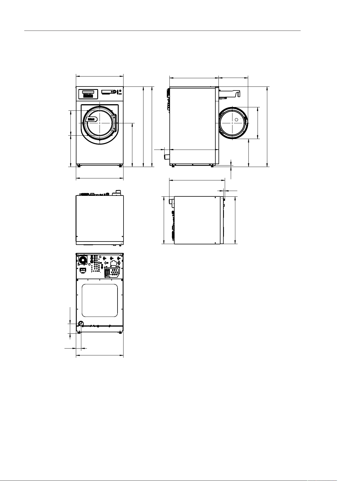
PW811
Dimensions
16.3"
20.9"
29.1"
53.2"
53.2"
31.5"
31.4"
37"
1"
31.5"
31.4"
3.4"
31.4"
6.5"
32.6"
3.5"
32.6"
19.4"
53.2"
18.6"
21"
0.9"
Dimensions in inches
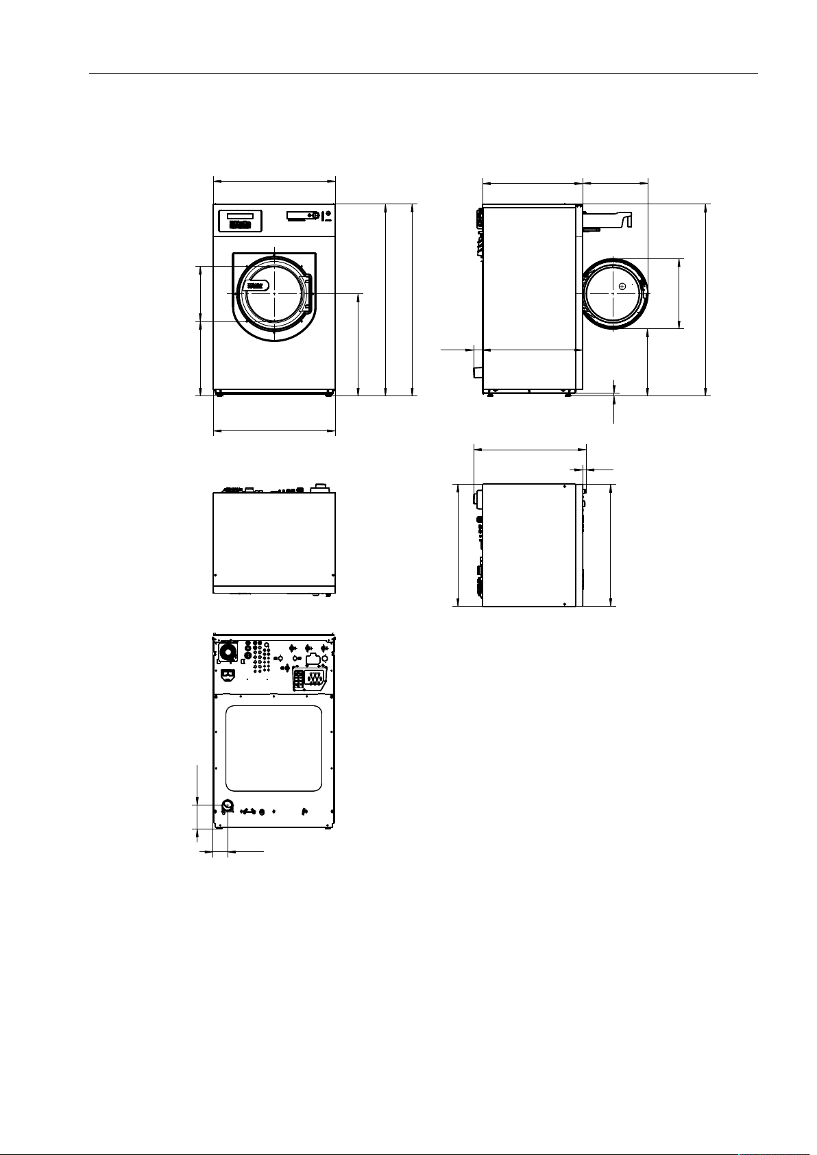
Technical drawings - dimensions in inches
PW 811 / PW 814 / PW 818 17
Dimensions with Mielebase (UG/UO)/weighting base (WI)
31.5"
32.3"
16.3"
31.4"
32.6"
19.4"
32.6"
3.5"
37"
1"
31.5"
31.4"
21"
30"
64.6"
64.6"
64.7"
40.5"
Dimensions in inches
Technical drawings - dimensions in inches
18 PW 811 / PW 814 / PW 818
Installation
≥ 50.4"
23"
33.3"
5.9"
≥ 50.4"
27.4"
3.6"
27.4"
13.7"
≥ 15.8"
≥ 15.8"
Dimensions in inches
Technical drawings - dimensions in inches
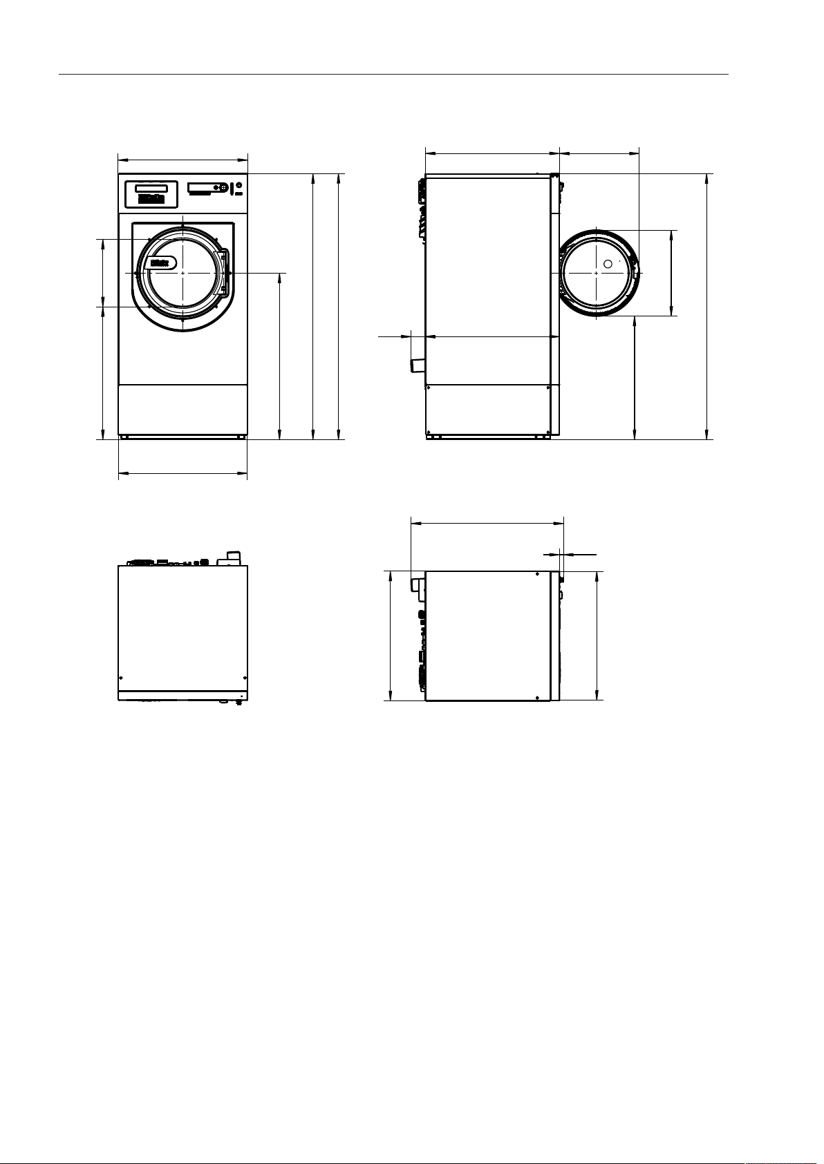
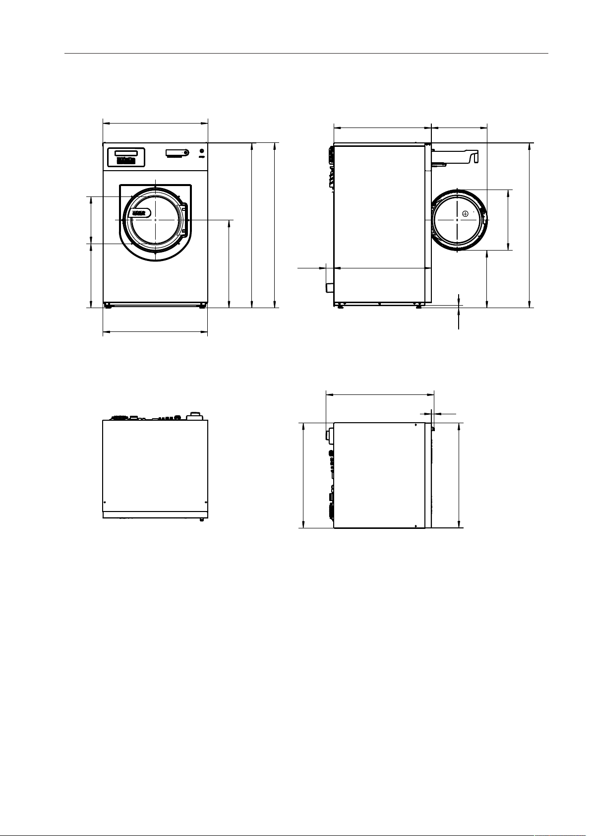
PW 811 / PW 814 / PW 818 19
PW814
Dimensions
16.3"
36.4"
22.3"
36.3"
30.4"
57.1"
57.2"
57.1"
29.8"
29.8"
2.7"
19.4"
21"
20"
0.9"
33.5"
1"
4.4"
7.1"
36.4"
36.3"
Dimensions in inches
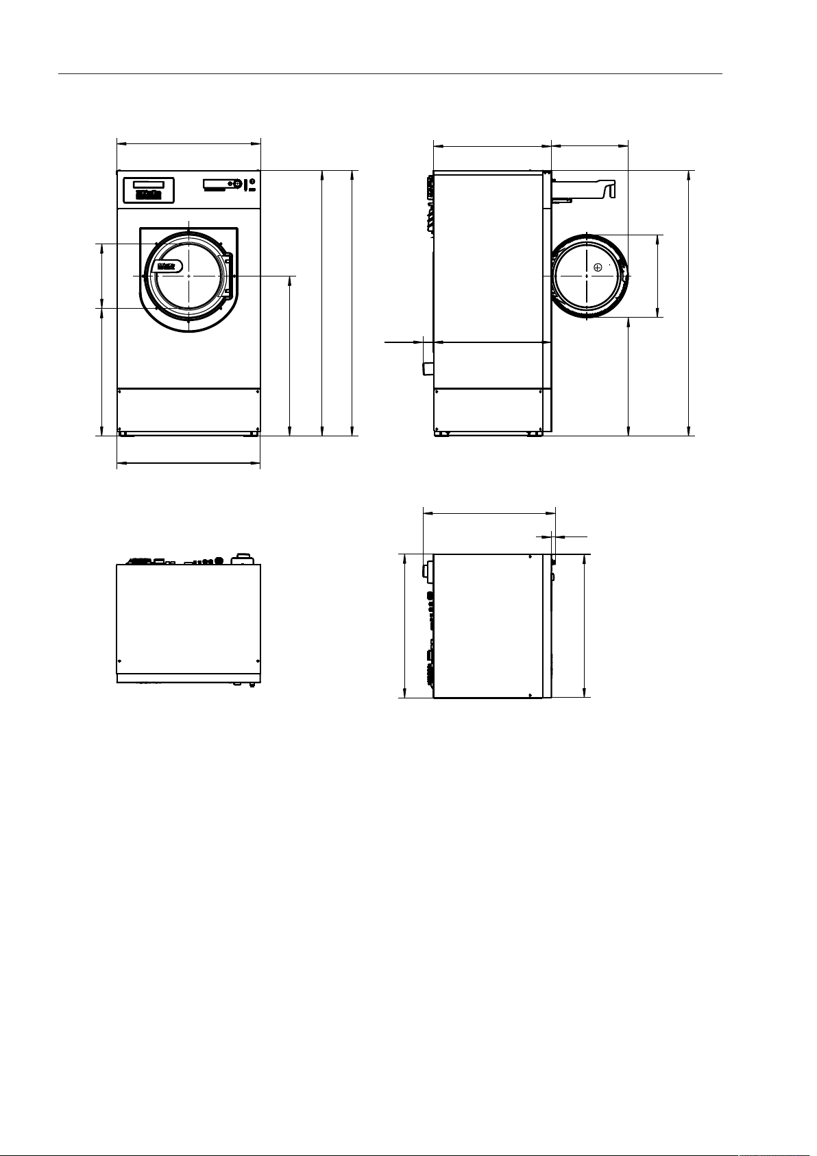
Technical drawings - dimensions in inches
20 PW 811 / PW 814 / PW 818
Dimensions with Mielebase (UG/UO)/weighting base (WI)
36.4"
32.3"
16.3"
36.3"
40.5"
67.2"
67.3"
29.8"
29.8"
2.7"
19.4"
67.2"
30
21"
36.3"
36.4"
33.5"
1"
Dimensions in inches

Technical drawings - dimensions in inches
PW 811 / PW 814 / PW 818 21
Installation
38.2"
16.2"
32.4"
24.7"
≥ 45.7"
≥ 45.7"
20.2"
5.8"
3.3"
≥ 15.8"
≥ 15.8"
Dimensions in inches
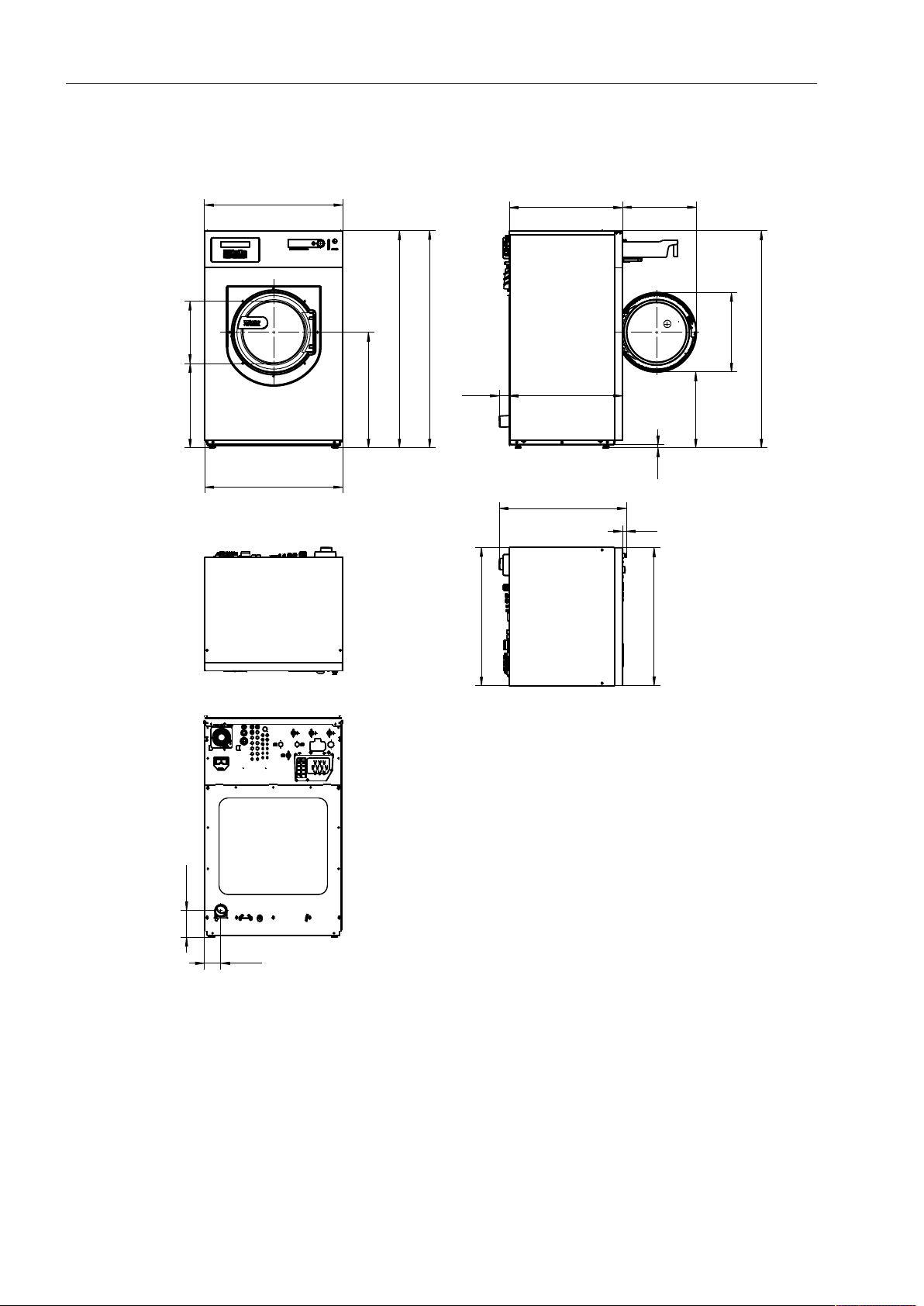
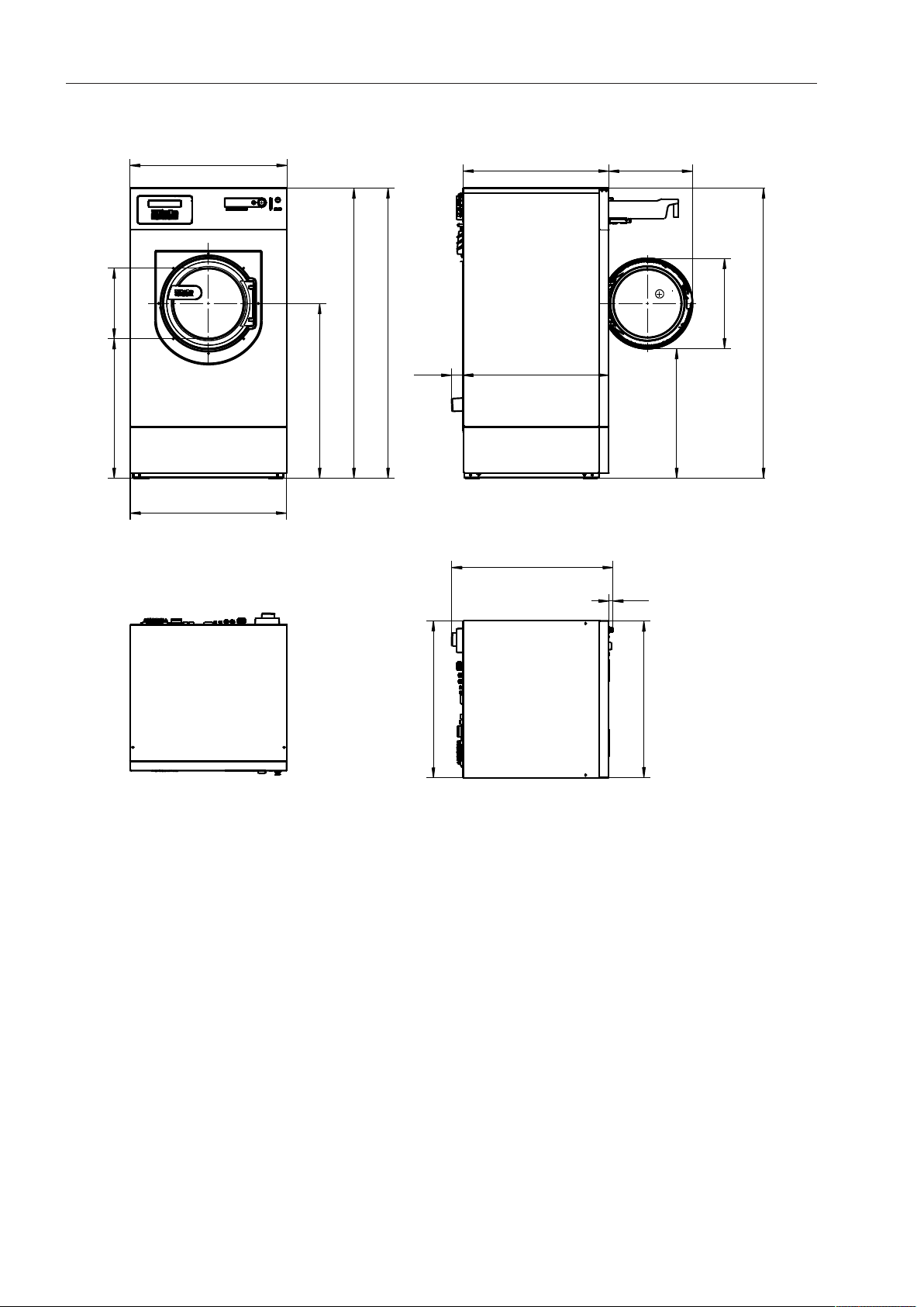
Technical drawings - dimensions in inches
22 PW 811 / PW 814 / PW 818
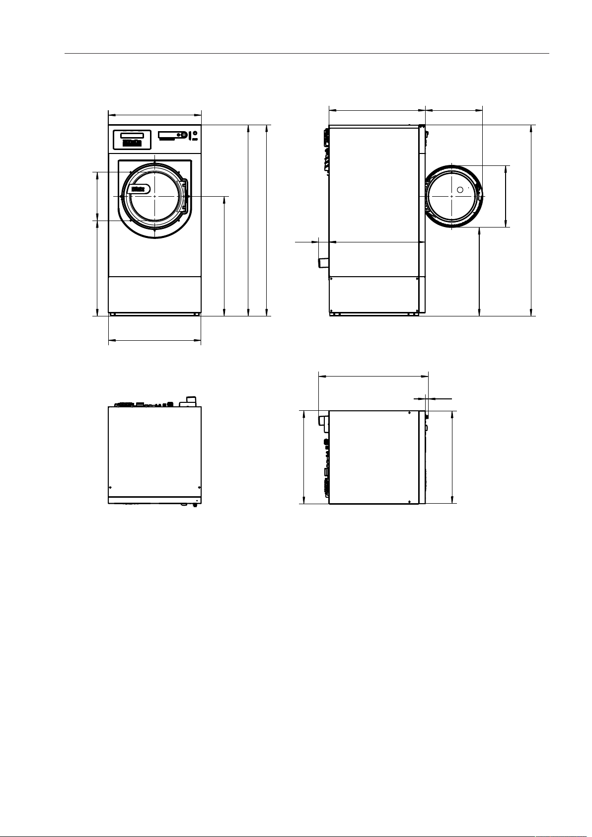
PW818
Dimensions
36.4"
36.3"
33.8" 19.4"
33.8"2.6"
37.4"
1"
16.3"
22.3"
30.4"
57.1"
57.2"
57.1"
21"
20"
0.9"
36.3"
36.4"
Dimensions in inches
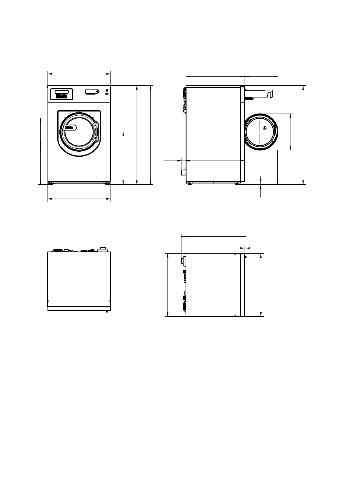
Technical drawings - dimensions in inches
PW 811 / PW 814 / PW 818 23
Dimensions with Mielebase (UG/UO)/weighting base (WI)
36.4"
36.3"
32.3"
16.3"
40.5"
67.2"
67.3"
67.2"
30"
21"
33.8"
19.4"
33.8"
2.6"
37.4"
1"
36.3"
36.4"
Dimensions in inches
Technical drawings - dimensions in inches
24 PW 811 / PW 814 / PW 818
Installation
38.2"
16.2"
32.3"
28.6"
≥ 49.6"
≥ 49.6"
24.1"
5.8"
3.2"
≥ 15.7"
≥ 15.7"
Dimensions in inches
Technical drawings - dimensions in inches
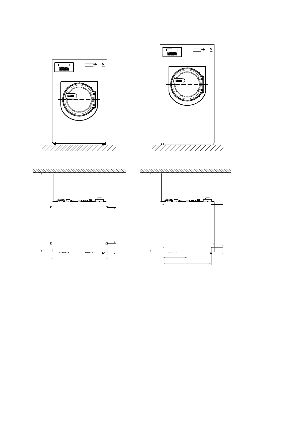
PW 811 / PW 814 / PW 818 25
Anchoring PW811/814/818
Attaching to the floor/concrete base
~ 3 1/2"
Ø 1/2"
Dimensions in inches
Attaching to the floor/concrete base when installing in a run
~ 3 1/2"
Ø 1/2"
Dimensions in inches
Technical drawings - dimensions in inches
26 PW 811 / PW 814 / PW 818
Attaching to the floor with Mielebase
~ 3 1/2"
Ø 1/2"
Dimensions in inches
Technical drawings - dimension in millimeters
PW 811 / PW 814 / PW 818 27
PW811
Dimensions
415
529
737
1350
1352
799
795
940
25
799
795
86
795
164
828
87
827
492
1350
472
531
22
Dimensions in millimeters
Technical drawings - dimension in millimeters
28 PW 811 / PW 814 / PW 818
Dimensions with Mielebase (UG/UO)/weighting base (WI)
799
820
415
795
827
492
828
87
940
25
799
795
531
762
1640
1640
1642
1027
Dimensions in millimeters
Technical drawings - dimension in millimeters
PW 811 / PW 814 / PW 818 29
Installation
≥ 1280
583
845
148
≥ 1280
697
91
696
348
≥ 400
≥ 400
Dimensions in millimeters
Technical drawings - dimension in millimeters
30 PW 811 / PW 814 / PW 818
PW814
Dimensions
415
924
564
921
772
1450
1452
1450
757
757
67
492
531
507
22
850
25
112
179
924
920
Dimensions in millimeters
Technical drawings - dimension in millimeters
PW 811 / PW 814 / PW 818 31
Dimensions with Mielebase (UG/UO)/weighting base (WI)
924
819
415
920
1027
1705
1707
758
757
67
492
1705
762
531
920
924
850
25
Dimensions in millimeters

Technical drawings - dimension in millimeters
32 PW 811 / PW 814 / PW 818
Installation
970
411
821
627
≥ 1160
≥ 1160
513
148
82
≥ 400
≥ 400
Technical drawings - dimension in millimeters
PW 811 / PW 814 / PW 818 33
PW818
Dimensions
924
920
857 492
85866
950
25
415
564
772
1450
1452
1450
531
507
22
920
924
Dimensions quoted in millimeters
Technical drawings - dimension in millimeters
34 PW 811 / PW 814 / PW 818
Dimensions with Mielebase (UG/UO)/weighting base (WI)
924
920
819
415
1027
1705
1707
1705
762
531
857
492
858
66
950
25
920
924
Dimensions quoted in millimeters
Technical drawings - dimension in millimeters
PW 811 / PW 814 / PW 818 35
Installation
970
411
821
727
≥ 1260
≥ 1260
613
148
82
≥ 400
≥ 400
Technical drawings - dimension in millimeters
36 PW 811 / PW 814 / PW 818
Anchoring PW811/814/818
Attaching to the floor/concrete base
~ 90
Ø 12
Dimensions in millimeters
Attaching to the floor/concrete base when installing in a run
~ 90
Ø 12
Dimensions in millimeters
Technical drawings - dimension in millimeters
PW 811 / PW 814 / PW 818 37
Attaching to the floor with Miele base
~ 90
Ø 12
Dimensions in millimeters

Technical data
38 PW 811 / PW 814 / PW 818
Water connection
Models with detergent dispenser drawer (WEK)
Permitted supply pressure 14.5-145 psi (1-10 bar)
Maximum intake rate 21 gal/min (79.5 l/min)
Cold water connection
(to be provided on site, external thread according to DIN 44991, flat seal)
2 x ¾"
Optional cold-hard water connection
(to be provided on site, external thread according to DIN 44991, flat seal)
2 x ¾"
Hot water connection≤158°F(70°C)
(to be provided on site, external thread according to DIN 44991, flat seal)
1 x ¾" (25 x 19 mm)
Intake hose length 59" (1500 mm)
Drain valve
Maximum drain water temperature 203°F (95°C)
Waste water connection (on machine) NPS 2 ¾" (DN 70) plastic pipe
Drain (on-site) 2 ¾" connection
Maximum drainage rate 53 gal/min (200 l/min)
Optional steam valves for steam-heated models
Electric steam valve (ELD01)
Regulatable steam pressure 29 - 145 psi (200 - 1000 kPa)
Connection size 1/2" (12 mm)
Connection voltage 1N AC 230V
Frequency 50-60Hz
Pneumatic steam valve (PND)
Regulatable steam pressure 0 - 145 psi (0 - 1000 kPa)
Connection size 1/2" (12 mm)
Connection for equipotential bonding
Connection with male thread (machine) 3/8" x 1 3/8" (10 x 35 mm)
Washers and nuts M10

Technical data
PW 811 / PW 814 / PW 818 39
Anchoring
Attaching to the floor
Required anchor points 2
Wood screw (diameterxlength) 1/2" x 31/2" (12mm x 90mm)
Wall anchors (diameter x length) 5/8" x 31/8" (16mm x 80 mm)
Attaching to the floor with Miele base
Required anchor points 4
Wood screw (diameterxlength) 1/2" x 31/2" (12mm x 90mm)
Wall anchors (diameter x length) 5/8" x 31/8" (16mm x 80 mm)
Attaching to a concrete base (provided on-site)
Required anchor points 2
Wood screw (diameterxlength) 1/2" x 31/2" (12mm x 90mm)
Wall anchors (diameter x length) 5/8" x 31/8" (16mm x 80 mm)

Technical data
40 PW 811 / PW 814 / PW 818
PW811
Electrical version and electrical data
Electrically heated
Standard
Connection voltage 3 AC 220-240 V
Frequency 60 Hz
Fuse rating (on site) 3 x 25 A
Power rating 10.2-11.8 kW
Rated current 3 x 23.2 A
Power cord, min. cross-section 4 x AWG 12
Cord connector M 32
Convertible to:
Connection voltage 3 AC 200-208 V
Frequency 60 Hz
Fuse rating (on site) 3 x 25 A
Power rating 8.8-9.4 kW
Rated current 3 x 21.2 A
Power cord, min. cross-section 4 x AWG 12
Cord connector M 32
Installation dimensions
Standard
Casing width (without add-on components) 31.4" (795 mm)
Casing height (without add-on components) 53.2" (1350 mm)
Casing depth (without add-on components) 32.6" (827 mm)
Overall machine width 31.5" (799 mm)
Overall machine height 53.3" (1352 mm)
Overall machine depth 37" (940 mm)
Minimum width of transport opening 31.7" (805 mm)
Minimum distance between wall and front of appliance 50.4" (1280 mm)
Minimum distance between wall and rear of appliance 15.8" (400 mm)
With Mielebase (UG/UO)
Casing width (without add-on components) 31.4" (795 mm)
Casing height (without add-on components) 64.6" (1640 mm)
Casing depth (without add-on components) 32.6" (827 mm)
Overall machine width 31.5" (799 mm)
Overall machine height 64.7" (1642 mm)
Overall machine depth 37" (940 mm)
Minimum width of transport opening 31.7" (805 mm)
Minimum distance between wall and front of appliance 50.4" (1280 mm)
Minimum distance between wall and rear of appliance 15.8" (400 mm)

Technical data
PW 811 / PW 814 / PW 818 41
Transport data, weight and floor load
Packaging width 44.5" (1130 mm)
Packaging height 57.8" (1468 mm)
Packaging depth 43" (1090 mm)
Gross volume 63.9 cu. ft. (1808 l)
Gross weight 701 lb (318 kg)
Net weight 642 lb (291 kg)
Maximum floor load during operation 4479 N
Emissions data
Workplace related sound pressure level, washing 51 dB (A)
Sound power level, washing 59.7 dB (A)
Workplace related sound pressure level, spinning 65 dB (A)
Sound power level, spinning 76.8 dB (A)
Average heat dissipation rate to installation site 3754 BTU (3.96 MJ/h)

Technical data
42 PW 811 / PW 814 / PW 818
PW814
Electrical version and electrical data
Electrically heated
Standard:
Connection voltage 3 AC 220-240 V
Frequency 60 Hz
Fuse rating (on site) 3 x 40 A
Power rating 14.8-17.1 kW
Rated current 3 x 37.2 A
Power cord, min. cross-section 4 x AWG 8
Cord connector M 40
Convertible to:
Connection voltage 3 AC 200-208 V
Frequency 60 Hz
Fuse rating (on site) 3 x 40 A
Power rating 12.5 - 13.4 kW
Rated current 3 x 32.4 A
Power cord, min. cross-section 4 x AWG 8
Cord connector M 40
Steam-heated
Standard:
Connection voltage 3AC 220-240 V
Frequency 60 Hz
Fuse rating (on site) 3 x 16 A
Power rating 2.3 kW
Rated current 3 x 4.0 A
Power cord, min. cross-section 4 x AWG 14
Cord connector M 25
Convertible to:
Connection voltage 3AC 200-208 V
Frequency 60 Hz
Fuse rating (on site) 3 x 16 A
Power rating 2.3 kW
Rated current 3 x 4.0 A
Power cord, min. cross-section 4 x AWG 14
Cord connector M 25

Technical data
PW 811 / PW 814 / PW 818 43
Installation dimensions
Standard
Casing width (without add-on components) 36.3" (920 mm)
Casing height (without add-on components) 57.1" (1450 mm)
Casing depth (without add-on components) 29.8" (757 mm)
Overall machine width 36.4" (924 mm)
Overall machine height 57.2" (1452 mm)
Overall machine depth 33.5" (849,5 mm)
Minimum width of transport opening 36.7" (930 mm)
Minimum distance between wall and front of appliance 45.7" (1160 mm)
Minimum distance between wall and rear of appliance 15.8" (400 mm)
With Mielebase (UG/UO)
Casing width (without add-on components) 36.3" (920 mm)
Casing height (without add-on components) 67.2" (1705 mm)
Casing depth (without add-on components) 29.8" (757 mm)
Overall machine width 36.4" (924 mm)
Overall machine height 67.3" (1707 mm)
Overall machine depth 33.5" (849.5 mm)
Minimum width of transport opening 36.7" (930 mm)
Minimum distance between wall and front of appliance 45.7" (1160 mm)
Minimum distance between wall and rear of appliance 15.8" (400 mm)
Transport data, weight and floor load
Packaging width 44.5" (1130 mm)
Packaging height 61.8" (1568 mm)
Packaging depth 43" (1090 mm)
Gross volume 68.2 cu. ft. (1931 l)
Gross weight 884 lb (401 kg)
Net weight 825 lb (374 kg)
Maximum floor load during operation 5400 N
Emissions data
Workplace related sound pressure level, washing 51 dB (A)
Sound power level, washing 59.6 dB (A)
Workplace related sound pressure level, spinning 65 dB (A)
Sound power level, spinning 76.2 dB (A)
Average heat dissipation rate to installation site Electrically heated versions: 5460 BTU (5.76 MJ/h)
Steam-heated versions: 787 BTU (0.83 MJ/h)

Technical data
44 PW 811 / PW 814 / PW 818
PW818
Electrical version and electrical data
Electrically heated
Standard:
Connection voltage 3 AC 220-240 V
Frequency 60 Hz
Fuse rating (on site) 3 x 50 A
Power rating 19.4-22.6 kW
Rated current 3 x 48 A
Power cord, min. cross-section 4 x AWG 8
Cord connector M 40
Convertible to:
Connection voltage 3 AC 200-208 V
Frequency 60 Hz
Fuse rating (on site) 3 x 50 A
Power rating 16.6-17.7 kW
Rated current 3 x 41.8 A
Power cord, min. cross-section 4 x AWG 8
Cord connector M 40
Steam-heated
Standard:
Connection voltage 3 AC 220-240 V
Frequency 60 Hz
Fuse rating (on site) 3 x 16 A
Power rating 3 kW
Rated current 3 x 4 A
Power cord, min. cross-section 4 x AWG 14
Cord connector M 25
Convertible to:
Connection voltage 3 AC 200-208 V
Frequency 60 Hz
Fuse rating (on site) 3 x 16 A
Power rating 3 kW
Rated current 3 x 4 A
Power cord, min. cross-section 4 x AWG 14
Cord connector M 25

Technical data
PW 811 / PW 814 / PW 818 45
Installation dimensions
Standard
Casing width (without add-on components) 36.3" (920 mm)
Casing height (without add-on components) 57.1" (1450 mm)
Casing depth (without add-on components) 33.8" (857 mm)
Overall machine width 36.4" (924 mm)
Overall machine height 57.2" (1452 mm)
Overall machine depth 37.4" (950 mm)
Minimum width of transport opening 36.7" (930 mm)
Minimum distance between wall and front of appliance 49.7" (1260 mm)
Minimum distance between wall and rear of appliance 15.8" (400 mm)
With Mielebase (UG/UO)
Casing width (without add-on components) 36.3" (920 mm)
Casing height (without add-on components) 67.2" (1705 mm)
Casing depth (without add-on components) 33.8" (857 mm)
Overall machine width 36.4" (924 mm)
Overall machine height 67.2" (1707 mm)
Overall machine depth 37.4" (950 mm)
Minimum width of transport opening 36.7" (930 mm)
Minimum distance between wall and front of appliance 49.7" (1260 mm)
Minimum distance between wall and rear of appliance 15.8" (400 mm)
Transport data, weight and floor load
Packaging width 44.5" (1130 mm)
Packaging height 61.8" (1568 mm)
Packaging depth 46.9" (1190 mm)
Gross volume 74.5 cu. ft. (1931 l)
Gross weight 997 (452 kg)
Net weight 937 lb (425 kg)
Maximum floor load during operation 6037 N
Emissions data
Workplace related sound pressure level, washing 54 dB (A)
Sound power level, washing 62.0 dB (A)
Workplace related sound pressure level, spinning 67 dB (A)
Sound power level, spinning 79.0 dB (A)
Average heat dissipation rate to installation site Electrically heated versions: 7110 BTU (7.56 MJ/h)
Steam-heated versions: 1024 BTU (1.08 MJ/h)

Please have the model and serial number
of your machine available when
contacting Technical Service.
U.S.A.
Miele, Inc.
National Headquarters
9 Independence Way
Princeton, NJ 08540
Phone:
Fax:
www.miele-pro.com
Technical Service & Support
800-991-9380
800-220-1348
Phone:
Fax:
800-991-9380
609-419-4241
Alteration rights reserved / Publication date: 0917 M.-Nr. 10 668 670 / 00
PW 811
PW 814
PW 818