INDOOR COOKING
All-Gas Range
KRG
Installation Manual
SAFETY DEFINITIONS
THIS INDICATES THAT DEATH OR SERIOUS INJURY MAY OCCUR
AS A RESULT OF NOT OBSERVING THIS WARNING.
THIS INDICATES THAT MINOR OR MODERATE INJURY MAY
OCCUR AS A RESULT OF NOT OBSERVING THIS WARNING.
THIS INDICATES THAT DAMAGE TO THE APPLIANCE OR
PROPERTY MAY OCCUR AS A RESULT OF NOT OBSERVING THIS
WARNING.
READ THESE INSTRUCTIONS CAREFULLY AND COMPLETELY BEFORE INSTALLING
OR USING YOUR APPLIANCE TO REDUCE THE RISK OF FIRE, BURN HAZARD, OR
OTHER INJURY. KEEP THIS MANUAL FOR FUTURE REFERENCE.
CAUTION
NOTICE
Do not store or use gasoline or other flammable vapors and liquids in the vicinity of
this or any other appliance.
WHAT TO DO IF YOU SMELL GAS:WHAT TO DO IF YOU SMELL GAS:
1. Do not try and light any appliance.
2. Do not touch any electrical switch.
3. Do not use any phone in your building.
4. Immediately call your gas supplier from a neighbor’s phone. Follow the gas
supplier’s instructions.
5. If you cannot reach your gas supplier, call the fire department.
Installation and service must be performed by a qualified installer, service agency, or
the gas supplier.
IF THE INFORMATION IN THIS MANUAL IS NOT FOLLOWED EXACTLY,
A FIRE OR EXPLOSION MAY RESULT CAUSING PROPERTY DAMAGE,
PERSONAL INJURY, OR DEATH.
INSTALLER: LEAVE THIS MANUAL WITH THE OWNER OF THE APPLIANCE.
HOMEOWNER: RETAIN THIS MANUAL FOR FUTURE REFERENCE.
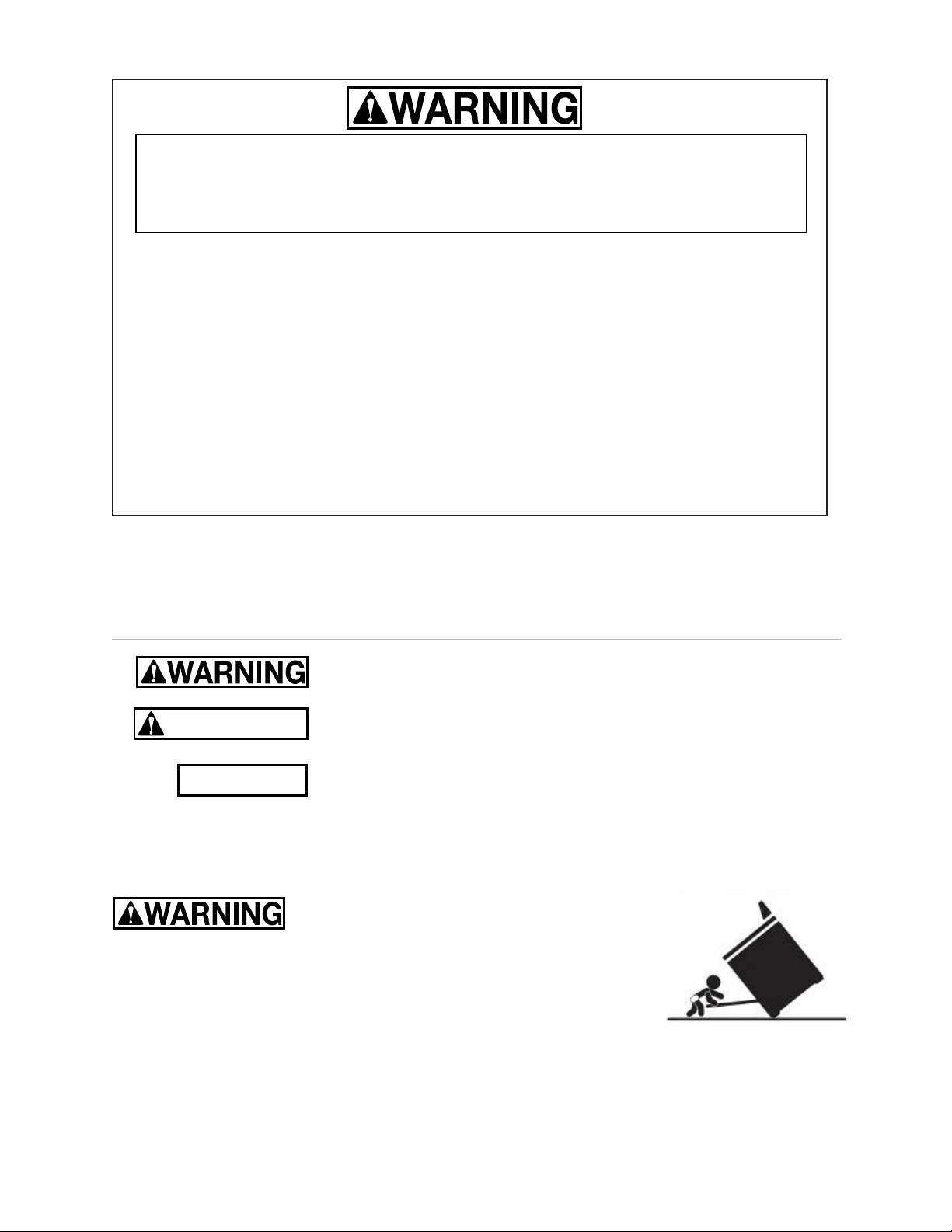
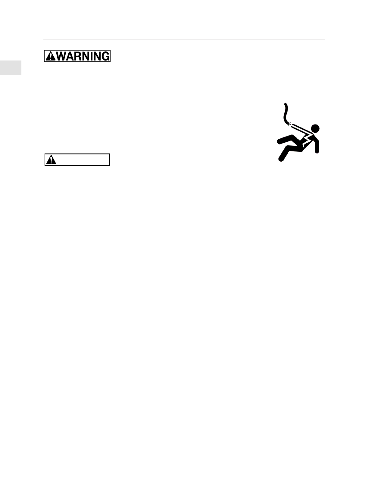
TIP OVER HAZARDTIP OVER HAZARD
A child or adult can tip over a range and be killed.
Check installation of the anti-tip device per the Installation Manual. Do not
operate the range without this device in place.
Check engagement of anti-tip device if range is moved, such as when cleaning behind the unit.
To check engagement, carefully tip the range forward while pulling from the rear of the unit. The
range should not move more that 1 inch [2.5cm].
Failure to follow these instructions can result in death or serious burns to children and adults.
To reduce the risk of burns, do not move this appliance while hot.

EN
©2020 Hestan Commercial Corporation
1
When properly cared for, your Hestan appliance will provide safe, reliable service for many years.
When using this appliance, basic safety practices must be followed as outlined below.
IMPORTANT: Save these instructions for the local Gas or Utility Inspector’s use.
INSTALLER: Please leave these Installation Instructions with the owner.
OWNER: Please retain these Installation Instructions for future reference.
This range is NOT designed for installation in manufactured (mobile) homes or recreational park
trailers. Do NOT install this range outdoors.
SAFETY PRECAUTIONS - BEFORE YOU BEGIN
ELECTRICAL SHOCK HAZARDELECTRICAL SHOCK HAZARD
Disconnect power before installing or servicing appliance. Before turning
power ON, be sure all controls are in the OFF position. Failure to do so can
result in electrical shock or death.
ELECTRICAL GROUNDINGELECTRICAL GROUNDING
This appliance must be grounded. Grounding reduces the risk of electric
shock in the event of a short circuit. Read the ELECTRICAL CONNECTIONS
section of this manual for complete instructions.
This appliance is equipped with a 3-prong grounding plug for your protection against shock hazard
and should be directly plugged into a properly grounded receptacle. Do not cut or remove the
grounding prong from this plug.
ELECTRICAL SUPPLYELECTRICAL SUPPLY
The appliance must be on its own dedicated circuit - 120 VAC, Single Phase, 60 Hz, with a current
rating as shown in the model number listing on pg. 2. Have the installer show you where the
electric circuit breaker is located so you know how to shut off the power to this appliance. It is the
responsibility of the user to have the appliance connected by a licensed electrician in accordance
with all local codes, or in the absence of local codes, in accordance with the National Electrical
Code. Read the ELECTRICAL CONNECTIONS section of this manual for complete details.
TABLE OF CONTENTS
1 SAFETY PRECAUTIONS - BEFORE YOU BEGIN
2 MODEL NUMBERS
3 RATING LABEL
3 REGULATORY / CODE REQUIREMENTS
3 LOCATION AND INSTALLATION / VENTILATION
14 BACKGUARD AND ACCESSORIES
14 INSTALLATION OF ANTI-TIP DEVICE
16 ELECTRICAL CONNECTIONS
17 GAS CONNECTION
19 FINAL SETUP
20 SERVICE
21 APPENDIX
EN
©2020 Hestan Commercial Corporation
2
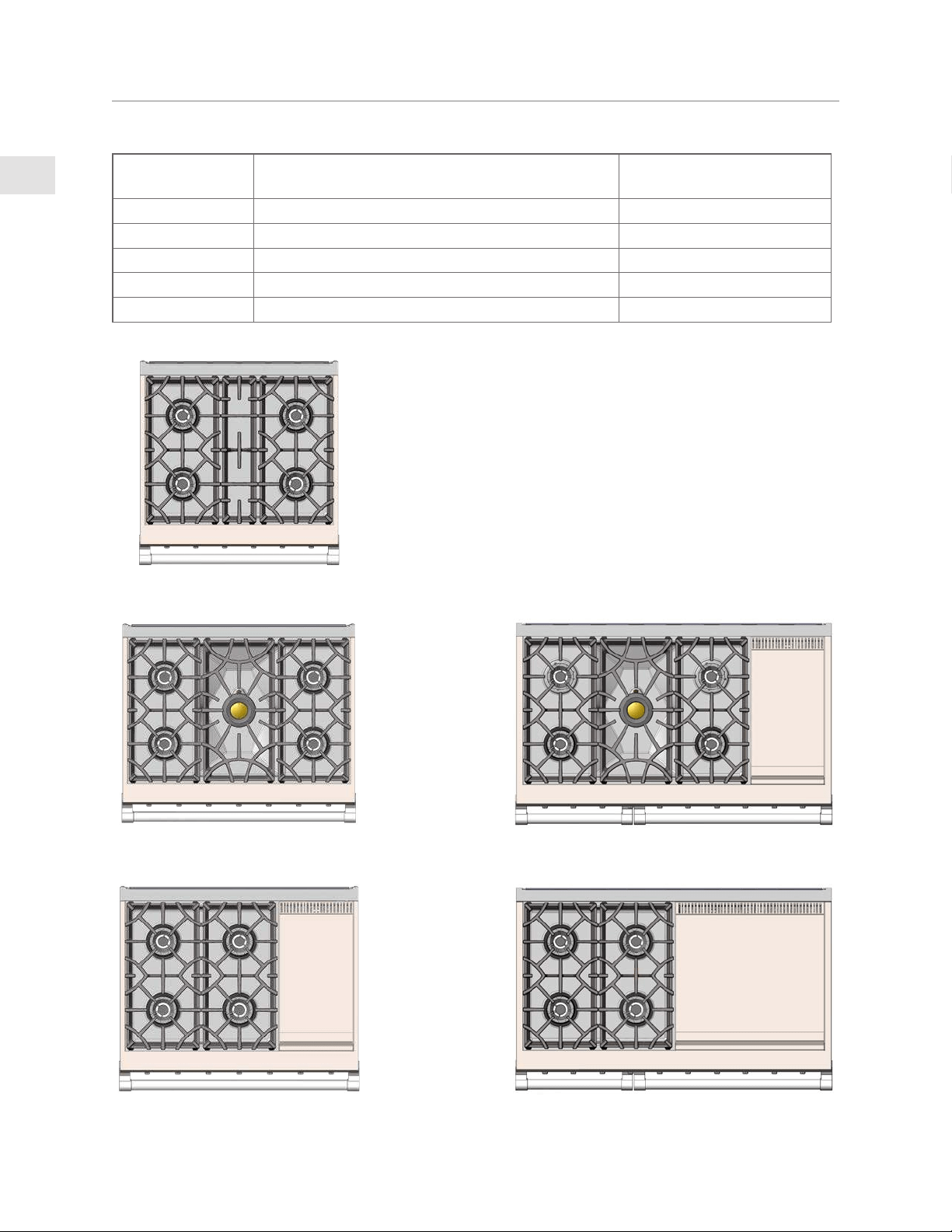
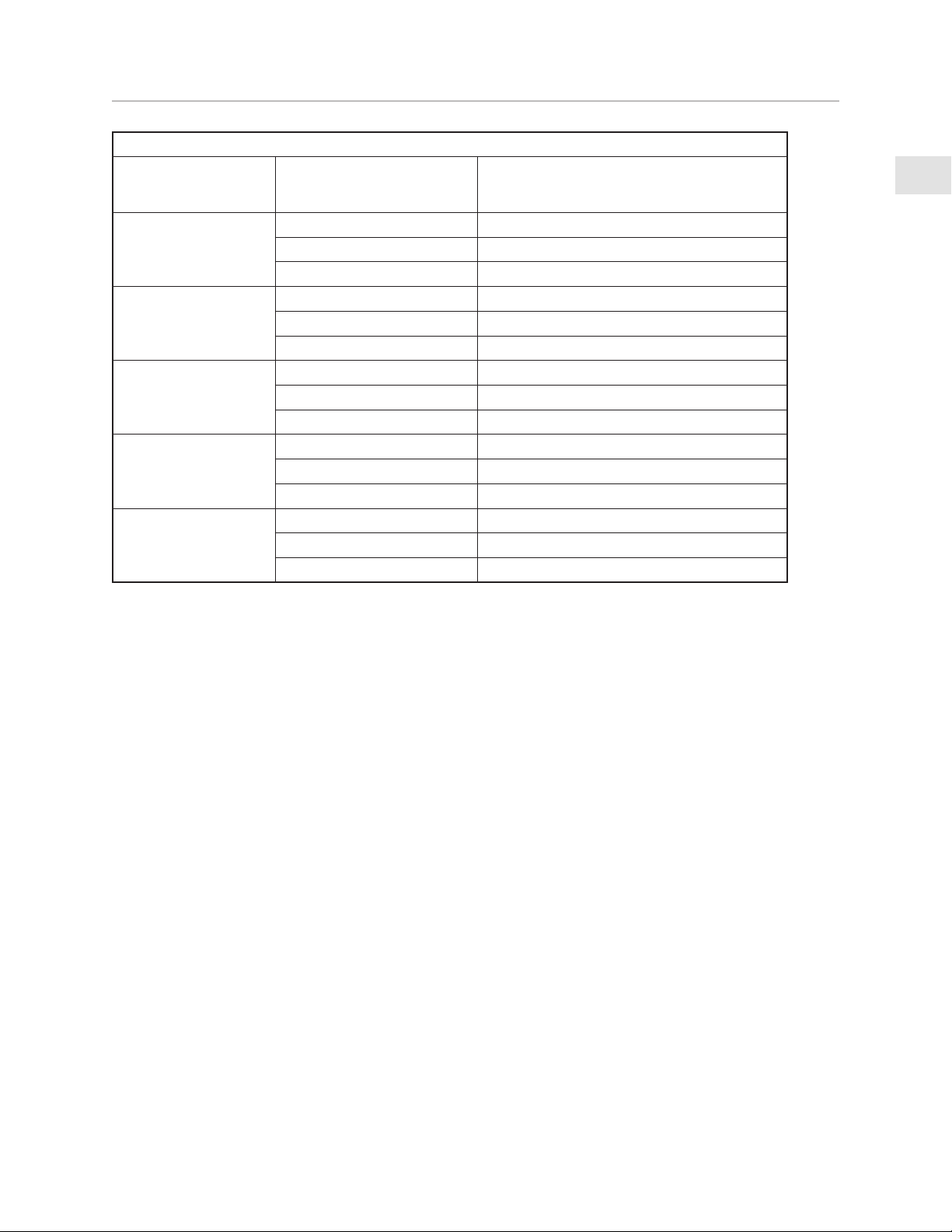
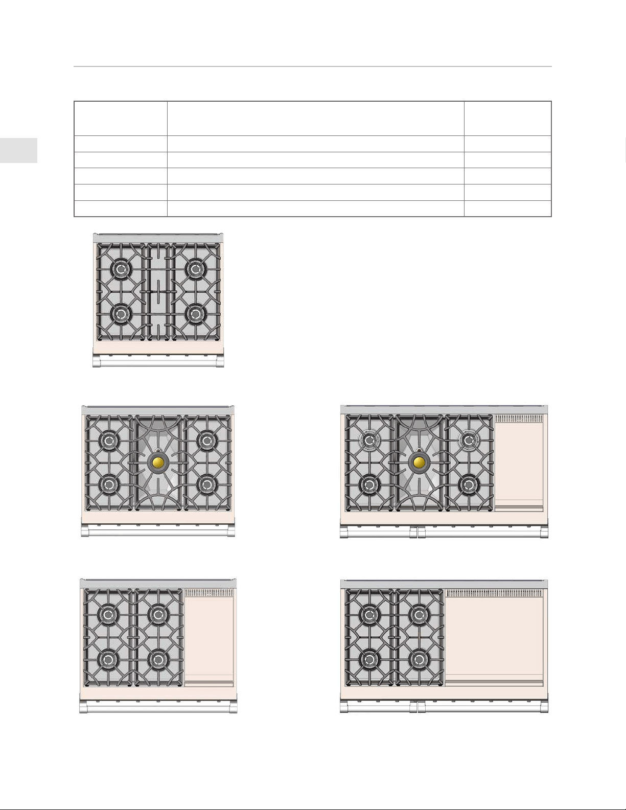
MODEL NUMBERS
RANGE MODELSRANGE MODELS
MODEL NO.MODEL NO. DESCRIPTIONDESCRIPTION
CIRCUIT BREAKER CIRCUIT BREAKER
REQUIREDREQUIRED
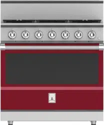
KRG304-NG / -LP 30” GAS RANGE WITH 4 BURNERS 15 Amp
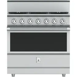
KRG365-NG / -LP 36” GAS RANGE WITH 5 BURNERS 15 Amp
KRG364GD-NG / -LP 36” GAS RANGE WITH 4 BURNERS & GRIDDLE 15 Amp
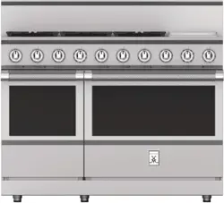
KRG485-NG / -LP 48” GAS RANGE WITH 5 BURNERS & 12” GRIDDLE 15 Amp
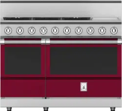
KRG484GD-NG / -LP 48” GAS RANGE WITH 4 BURNERS & 24” GRIDDLE 15 Amp
KRG365KRG365
KRG304KRG304
KRG485GDKRG485GD
KRG484GDKRG484GDKRG364GDKRG364GD
EN
©2020 Hestan Commercial Corporation
3
REGULATORY / CODE REQUIREMENTS
Installation of this cooking appliance must be made in accordance with local codes. In the absence
of local codes, this unit should be installed in accordance with the National Fuel Gas Code
ANSI
Z223.1/NFPA 54
, Natural Gas and Propane Installation code
CSA B149.1
, or Propane Storage and
Handling Code
B149.2
.
All Electrical Components must be electrically grounded in accordance with local codes or in the
absence of local codes with the National Electrical Code
ANSI/NFPA 70
, or Canadian Electrical code
CSA C22.1
.
STATE OF MASSACHUSETTSSTATE OF MASSACHUSETTS
Massachusetts requires all gas be installed using a plumber or gas fitter carrying the appropriate
Massachusetts license. All permanently installed natural gas or propane installations require a
T handle type manual gas valve be installed in the gas supply line to this appliance. Flexible gas
connector must not be longer than 48” [1.2 m].
CALIFORNIA PROPOSITION 65 - WARNINGCALIFORNIA PROPOSITION 65 - WARNING
WARNING:WARNING: This product can expose you to chemicals including carbon monoxide, which is
known to the State of California to cause birth defects or other reproductive harm.
For more information, go to www.P65Warnings.ca.gov.
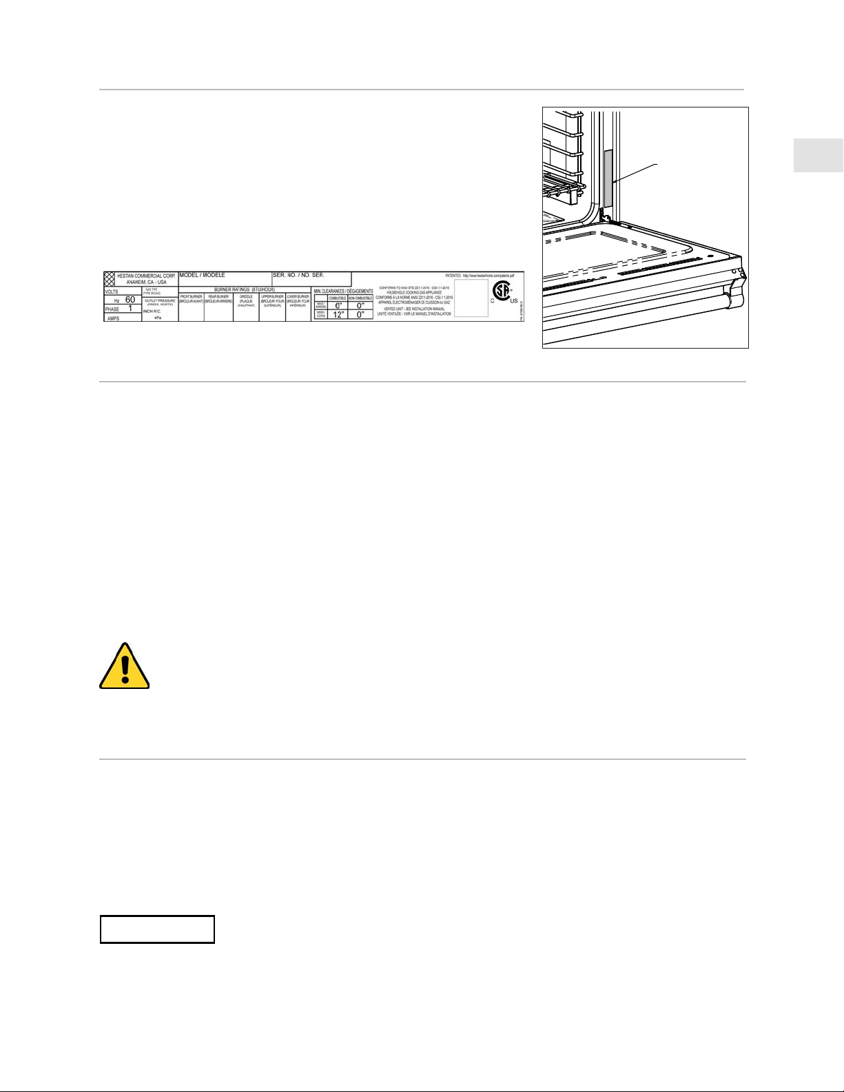
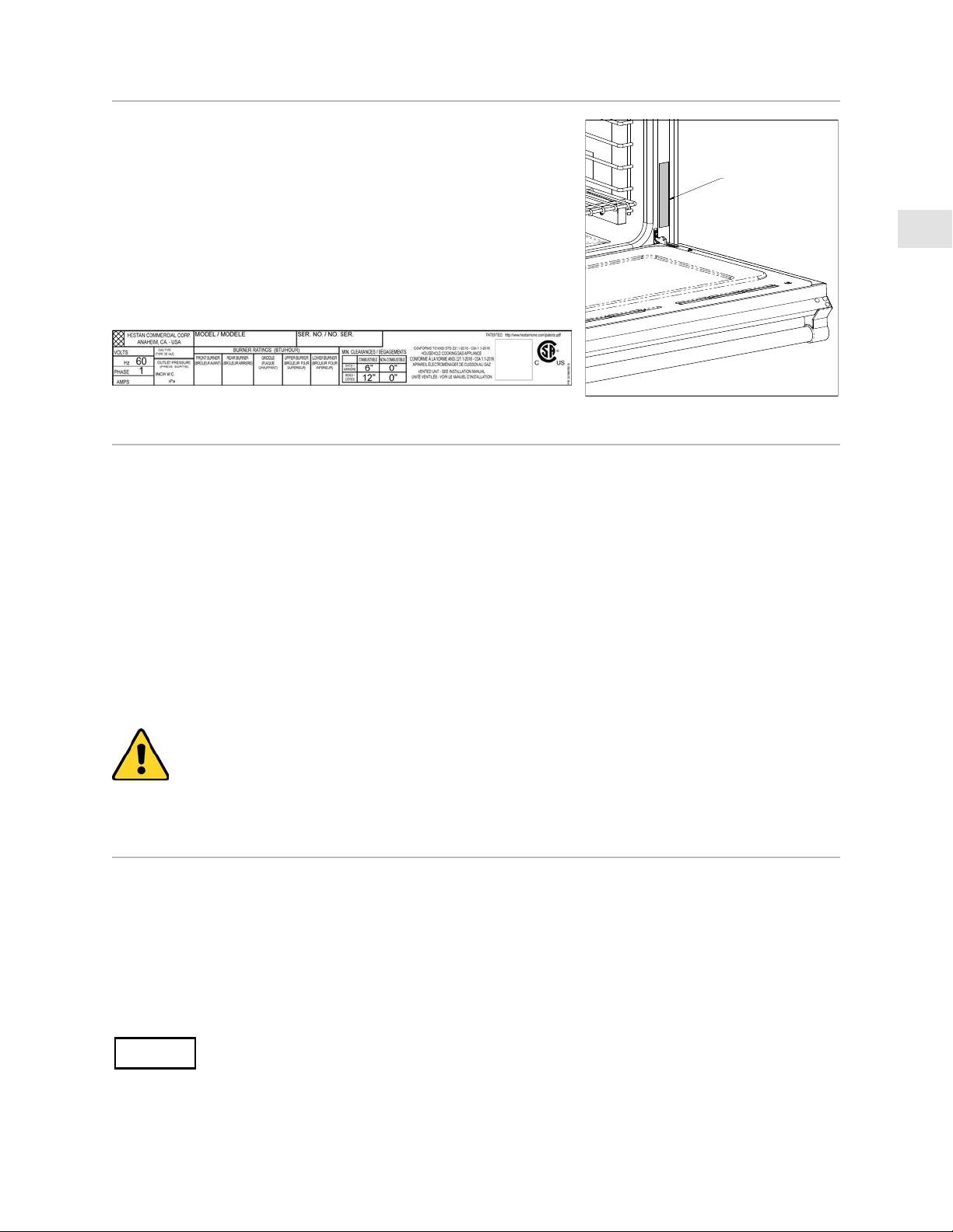
RATING
LABEL
RATING LABEL
The rating label contains important information about your
Hestan appliance such as the model and serial number,
gas type and manifold pressure, electrical rating, the BTU
rating for each burner type, and the minimum installation
clearances.
The rating label is located on the right side of the oven cavity
opening near the door hinge.
If service is necessary, contact Hestan Customer Care with
the model and serial number information shown on the label.
LOCATION AND INSTALLATION / VENTILATION
UNPACKING AND PLACEMENTUNPACKING AND PLACEMENT
Remove the outer carton and packing materials from the shipping pallet. Do not remove the plastic
film covering the stainless-steel surfaces. This film protects the finish from scratches until the
appliance is installed in its final position.
The unit is very heavy and should be handled with care. Use proper safety equipment, such as gloves,
and at least 2 persons to move the appliance into position to avoid injury and to avoid damage to the
floor or the appliance itself.
DO NOT USE A HAND TRUCK OR DOLLY ON THE FRONT OR REAR OF THE
RANGE. HANDLE AND MOVE FROM THE SIDES ONLY.
Do not lift or carry the appliance by the oven door or handle. This could damage the door hinges.
NOTICE
EN
©2020 Hestan Commercial Corporation
4
LOCATION AND INSTALLATION / VENTILATION
(CONTINUED)
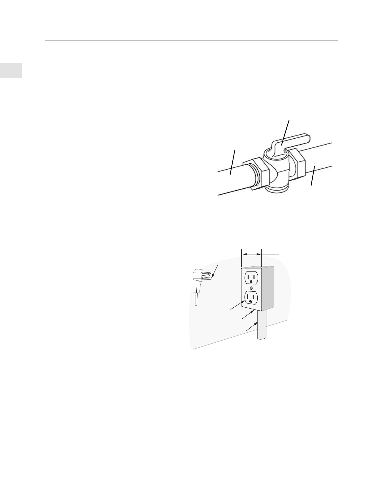
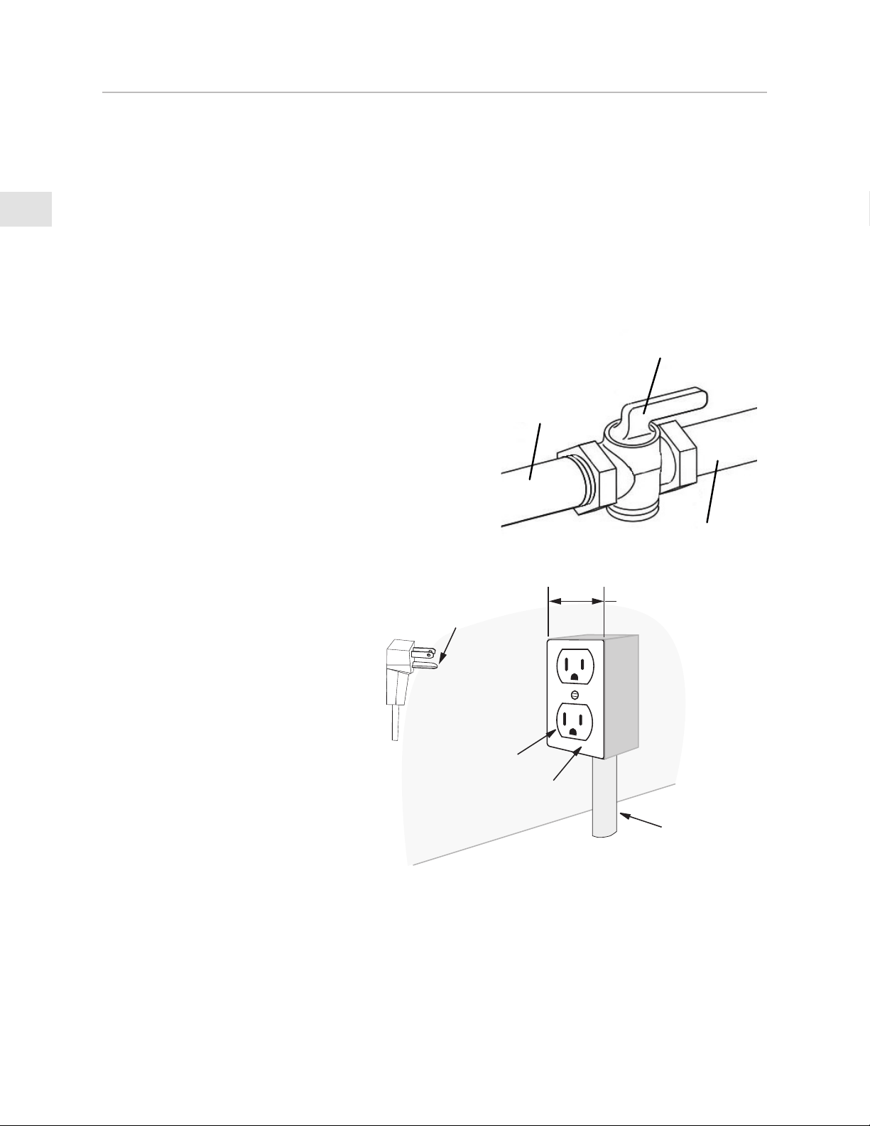
GAS
SUPPLY
TO
APPLIANCE
SHUTOFF VALVE
IN OPEN POSITION
The range is held onto the pallet with 4 large shipping bolts on both sides. Remove these bolts and
then move the range to the floor with the help of 2 persons.
PREPARATIONPREPARATION
Before moving the range, protect any finished flooring and secure the oven door(s) closed to
prevent damage.
GAS AND ELECTRICAL SUPPLY CLEARANCESGAS AND ELECTRICAL SUPPLY CLEARANCES
If not already in place, install a gas shut-off valve in
an easily accessible location for servicing of the range.
Make sure all users of the range know where this shut-
off is located, and how to shut off the gas. Any openings
in the wall or floor behind the appliance must be sealed.
The Installation Clearances on the following pages show
where the “G” and “E” zones should be located.
The range is designed to be installed nearly flush to the
rear wall*. It may be necessary to reposition the gas
supply and power receptacle / junction box in order to
accommodate the range when pushed back against the
wall.
The back of the range is recessed 3-1/4” [8.3 cm] to
provide room for the cord and gas pipe. If using a
wall-mounted junction box/outlet, it may need to be
mounted to direct the cord along the wall instead of
toward the range.
* Unless installed in an island with no rear wall.
CABINETRYCABINETRY
To eliminate the risk of burns or fire by reaching over heated surface units, cabinet storage space
located above the surface units should be avoided. If cabinet storage is to be provided, the risk can
be reduced by installing the required vent hood that projects horizontally a minimum of 5” [12.7
cm] beyond the bottom of the cabinets.
3-1/4” max.
wall to back
of range
box mounted
against wall to
direct cord
along wall
Grounding pin
3-Prong receptacle
Grounded receptacle box
Conduit
EN
©2020 Hestan Commercial Corporation
5
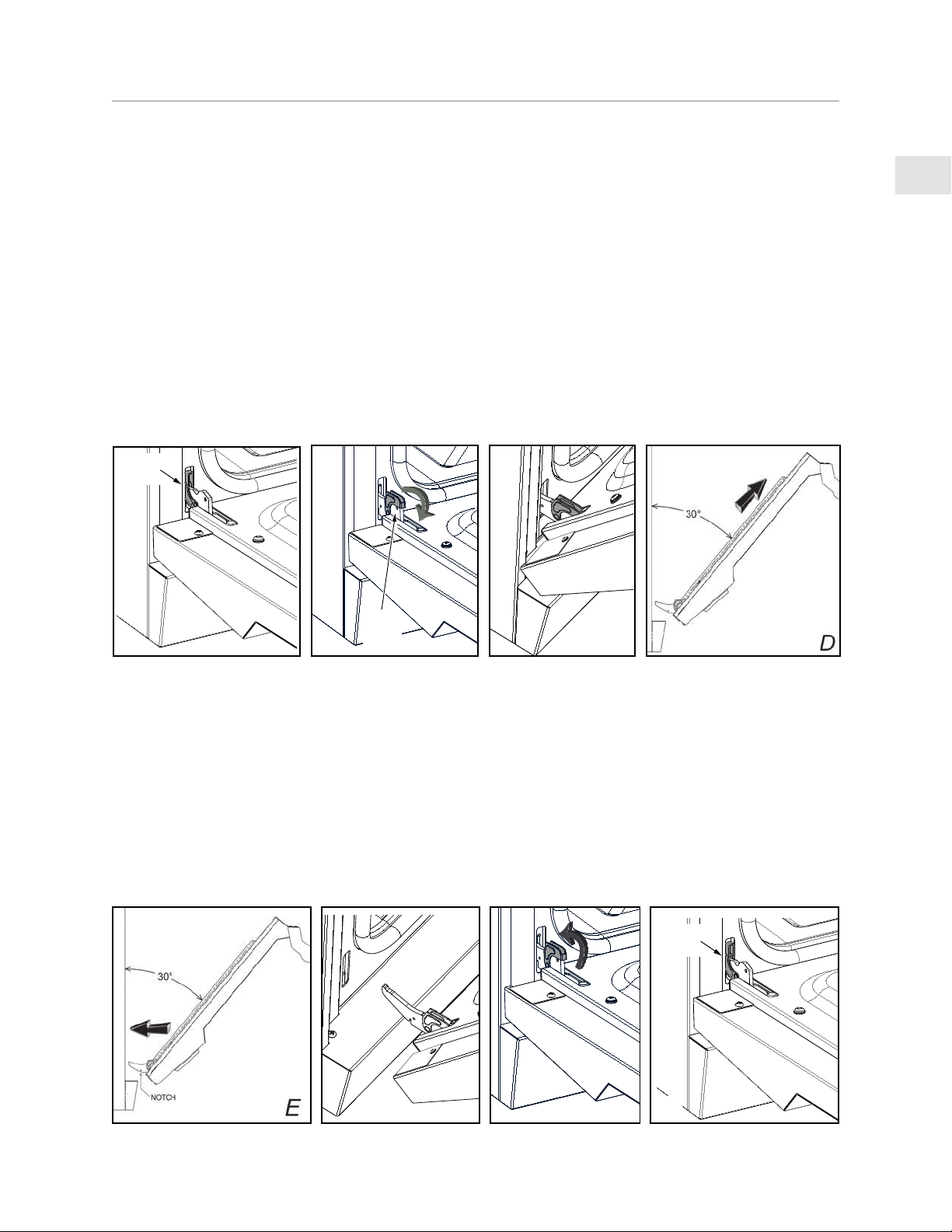
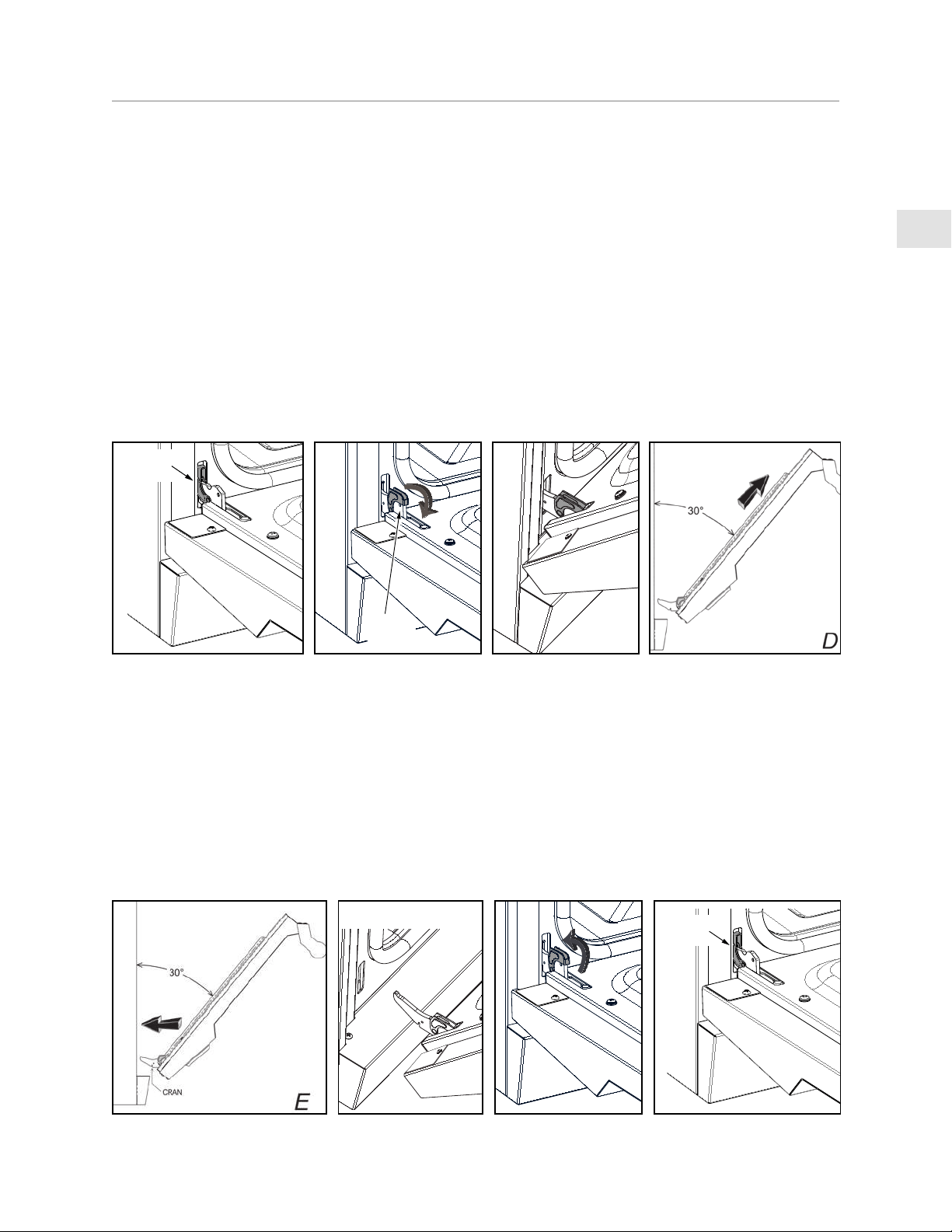
OVEN DOOR REMOVAL OVEN DOOR REMOVAL
If you have a very narrow door opening to your kitchen, the oven door(s) can be removed. REMOVE
ONLY IF ABSOLUTELY NECESSARY. Door removal should only be done by a certified installer or
service technician. Be sure the oven has completely cooled and the electrical power is off. Failure
to do so may result in electric shock or burn injury. Use caution when removing the door, it is very
heavy.
1. Open oven door completely.
2. At each hinge location, swing the hinge clip forward until it stops. A screwdriver may be needed
to do this. [ B ]
3. Gently close the oven door until it stops against the hinge clips, or approximately 30° from the
closed position. Hold on firmly to both sides of the door (not the handle) and pull the door
straight up off the hinges. Place the oven door in a safe location until needed. NEVER release
the hinge clips and try to close the hinges. Doing so will snap the hinges closed with great force
which could cause injury. [ C & D ]
Hinge
clip
A
B
Hinge
clip
C
G
Hinge
clip
H
LOCATION AND INSTALLATION/VENTILATION
(CONTINUED)
RE-INSTALL OVEN DOORRE-INSTALL OVEN DOOR
1. Hold the door firmly on both sides (NOT FROM THE HANDLE) at approximately 30° from the
closed position and insert the hinges into the slots in the oven. The bottom edge of each hinge
has a notch which must seat inside the slot opening. DO NOT FORCE OR BEND OR TWIST
THE DOOR! [ E & F ]
2. Slowly open the door all the way. Swing the hinge clips away from you until completely inside
the slot opening and fully seated. A screwdriver may help you do this. [ G ]
3. Gently close the oven door to check for smooth operation.
F
EN
©2020 Hestan Commercial Corporation
6
LOCATION AND INSTALLATION/VENTILATION
(CONTINUED)
LEVELING LEVELING
The range must be level, especially those models featuring a griddle. Raise or lower the range to the
desired height by adjusting the four leveling legs under the range (48” units have 6 legs). The legs can
be turned by hand. It may be necessary to use a lever or other lifting device to assist in temporarily
raising the unit to turn the legs. Do not lift or lever from the front or back, only from the sides.
The appliance top must be level or higher than the adjacent countertop surfaces. Failure to adjust
the height may expose the adjacent cabinets to excessive heat which may
damage the cabinets or countertop.
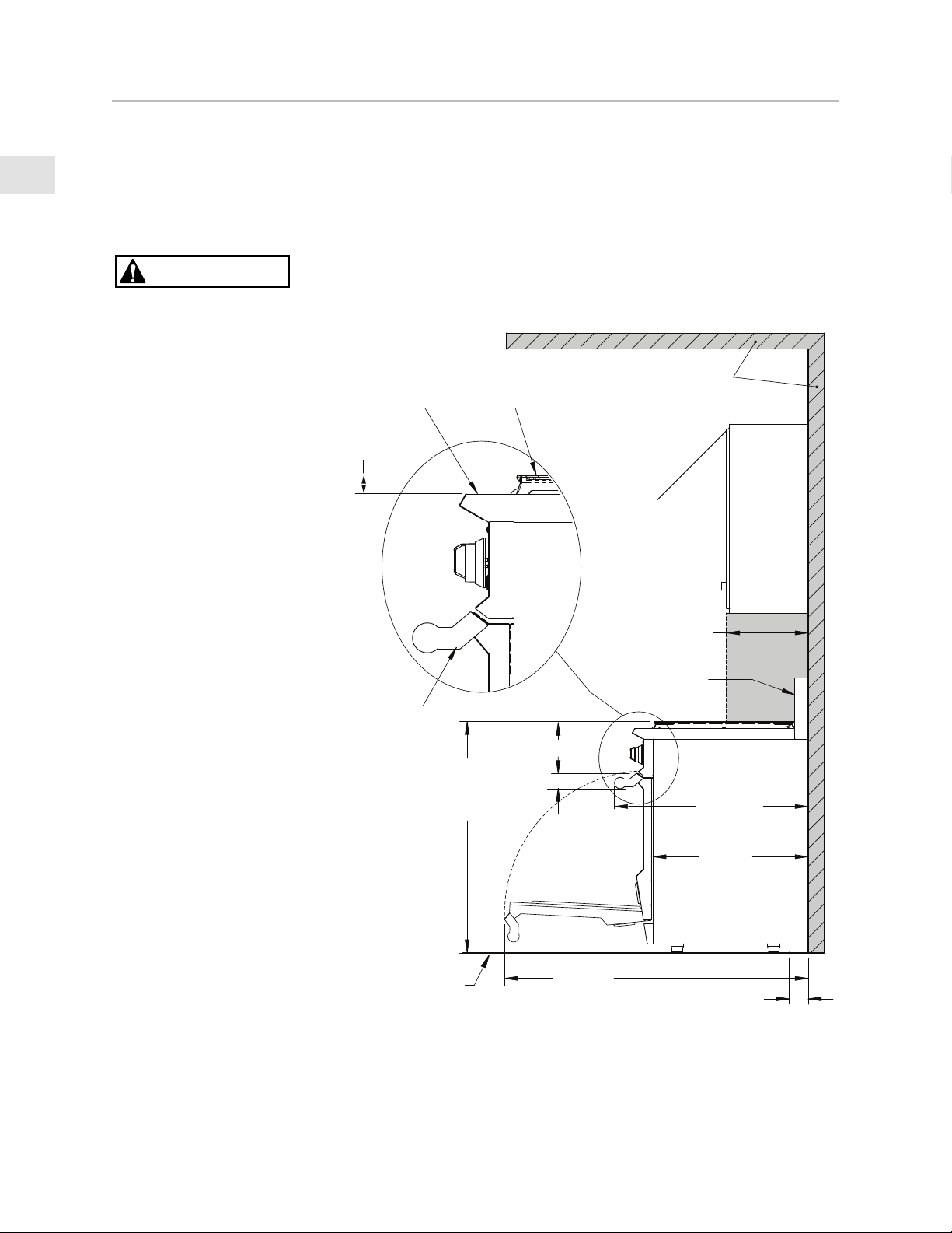
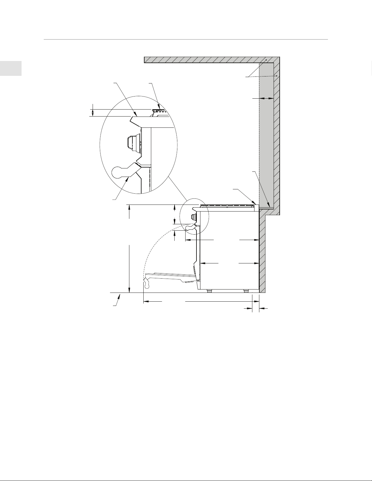
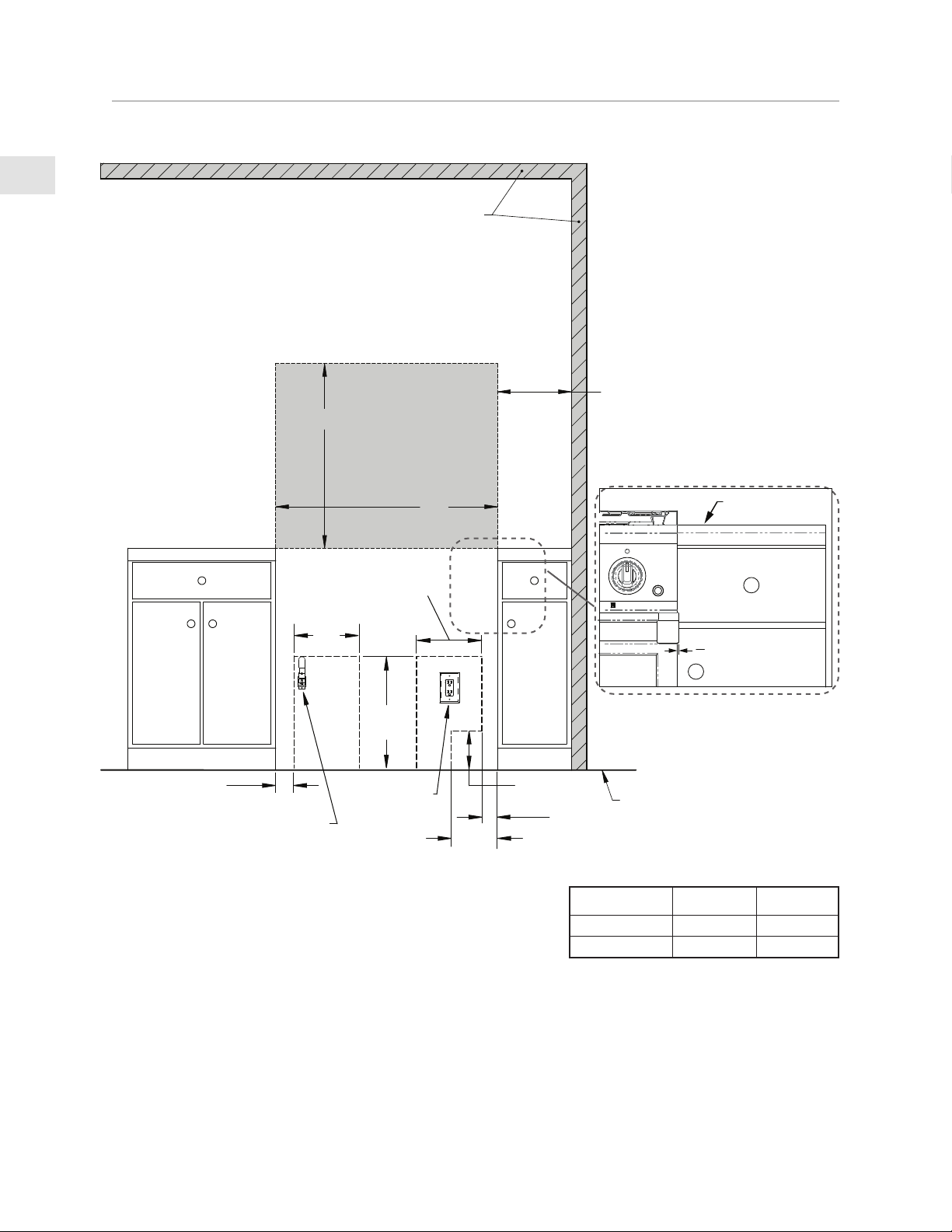
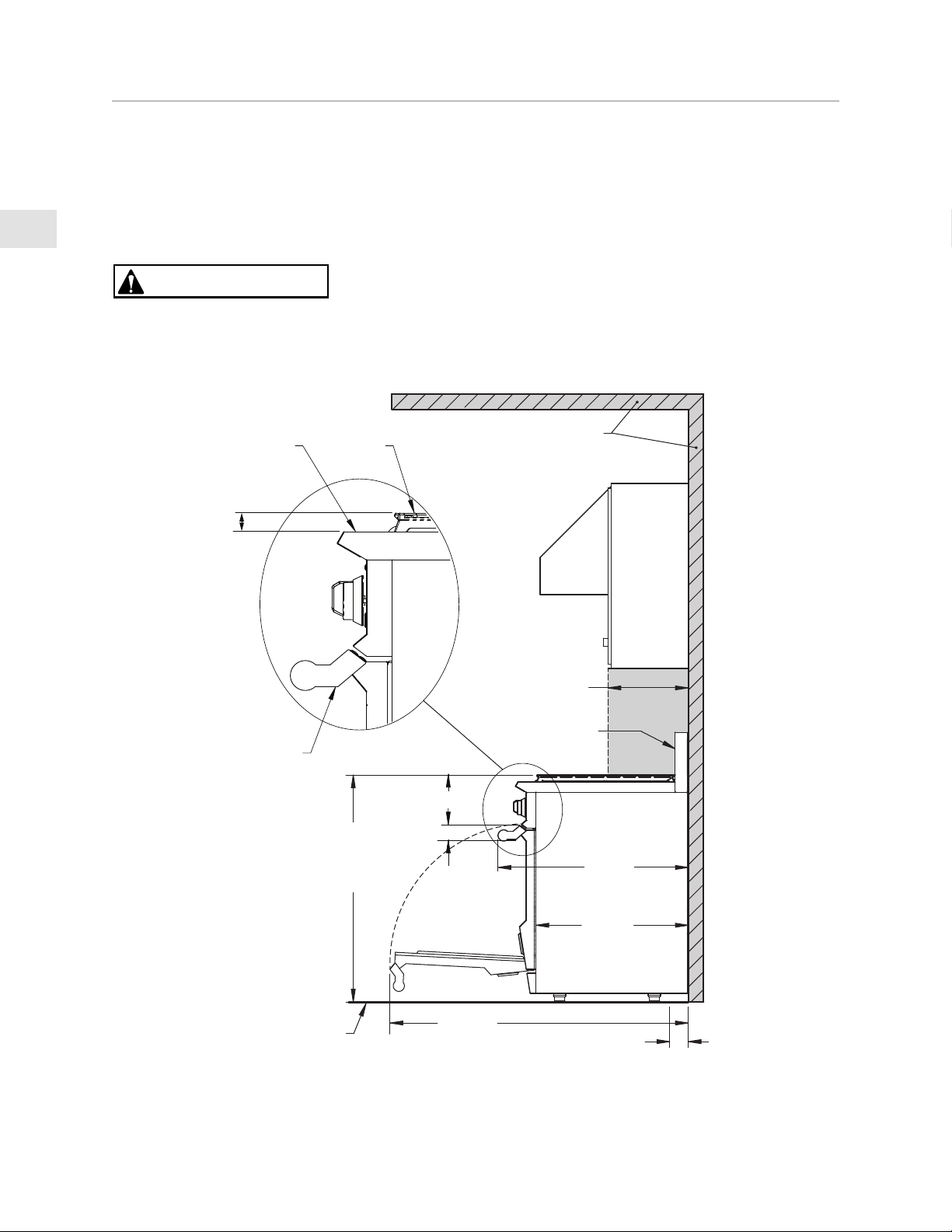
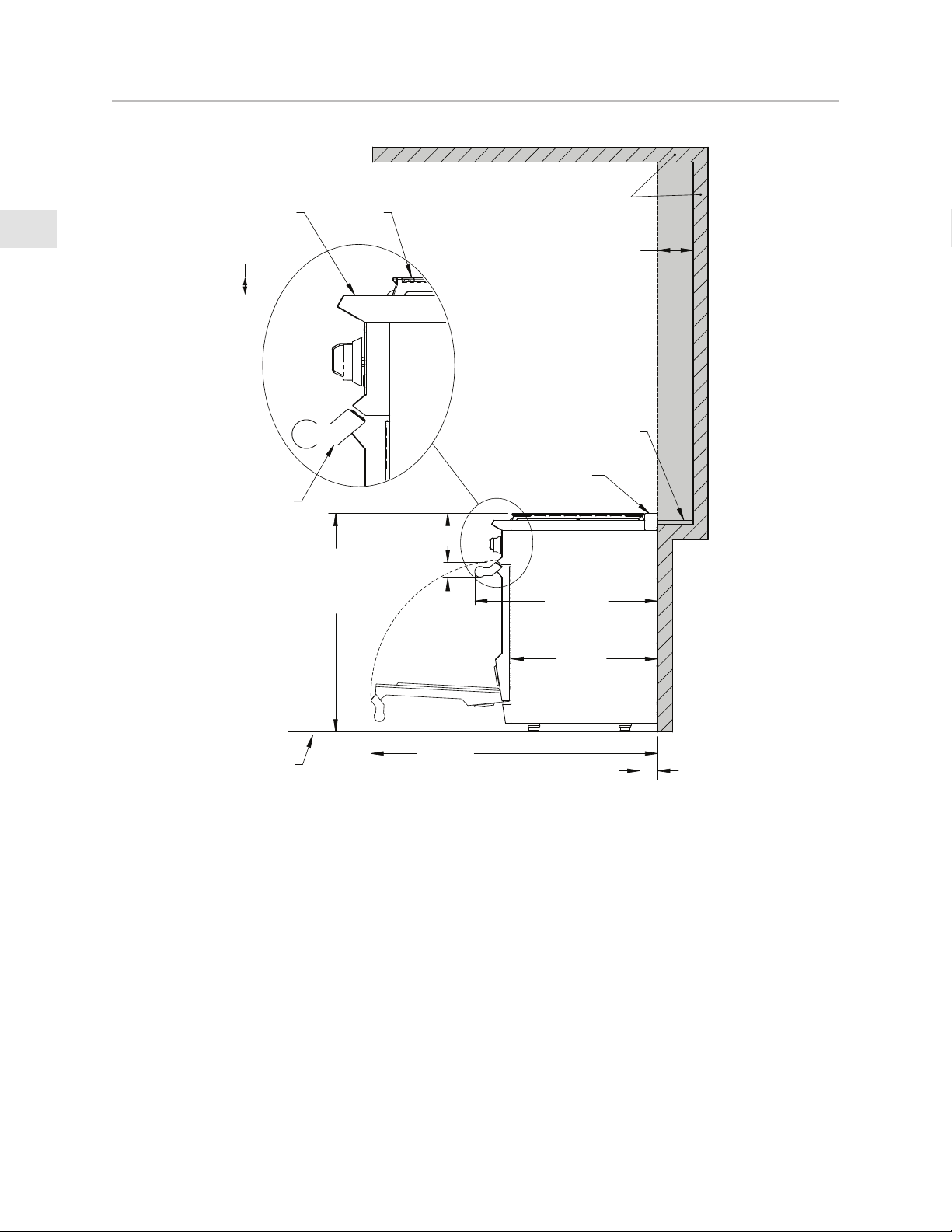
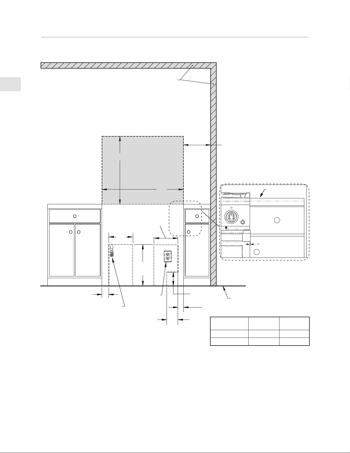
INSTALLATION CLEARANCES WITH LOW BACKGUARD
SIDE VIEW
38-3/8 - 36-7/8”
[97.5 - 93.7]
TO COOKING
SURFACE
APPLIANCE
TOP
HANDLE
END CAP
COOKING
SURFACE
COMBUSTIBLE
MATERIALS
30-13/16”
[78.3]
24-11/16”
[62.7]
13” [33]
7” [17.7]
2-5/8”
[6.7]
MAX.
LOW
BACKGUARD
MAX.
RECESS
DEPTH
FINISHED
FLOOR
48-5/16”
[122.7]
3”
[7.6]
DIMENSIONS IN BRACKETS [ ] ARE IN CM.
LOCATION OF GAS AND
ELECTRICAL ON FLOOR
REF 1.12”
[2.84]
VENT
HOOD
CAUTION
EN
©2020 Hestan Commercial Corporation
7
LOCATION AND INSTALLATION/VENTILATION
(CONTINUED)
FINISHED
FLOOR
VENT HOOD
COMBUSTIBLE
MATERIALS
MIN. CLEARANCE
TO NEAREST
COMBUSTIBLE
SIDE SURFACE
W
V
DIMENSIONS IN
BRACKETS [ ] ARE
IN CM.
COUNTERTOP
FULL OVERLAY
DRAWER FACE
FULL OVERLAY
CABINET DOOR FACE
1
8
"
[3.2 mm]
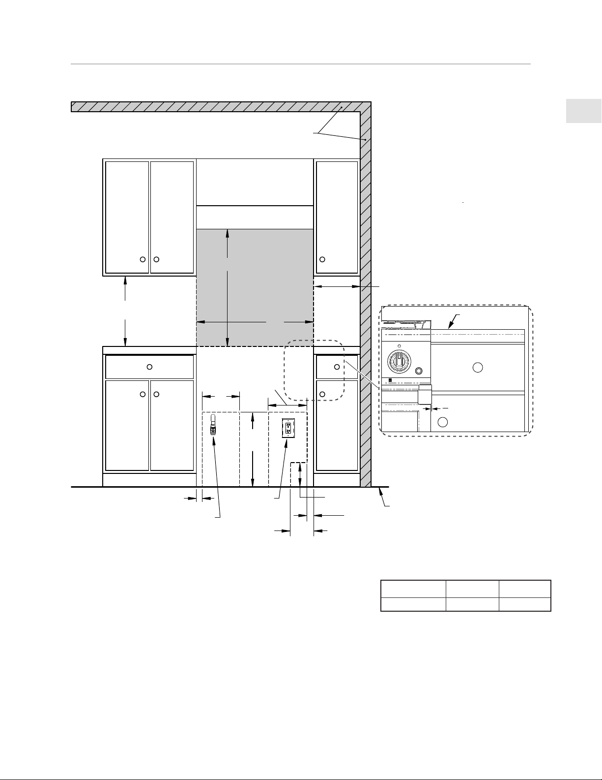
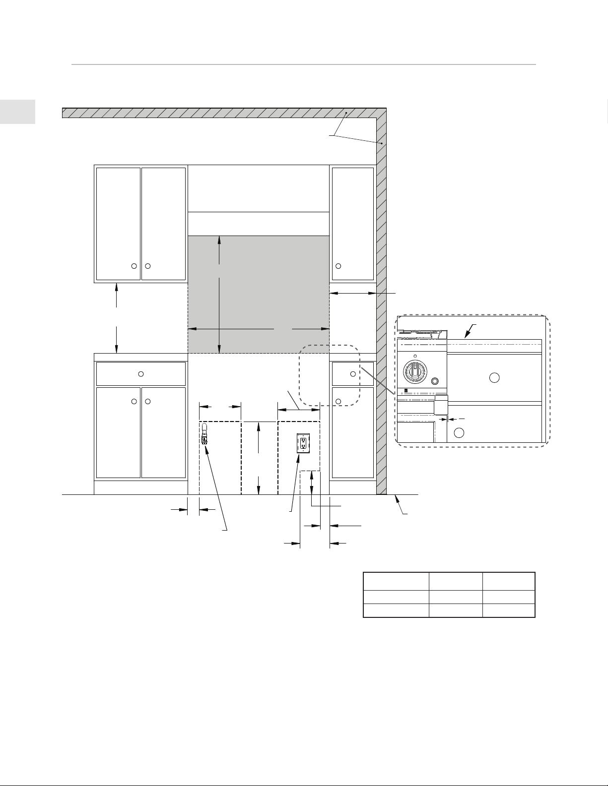
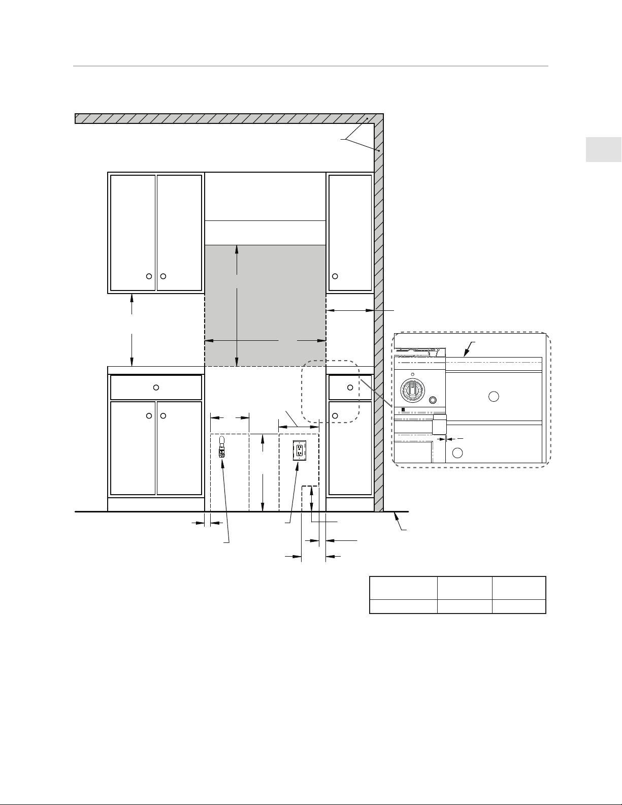
INSTALLATION CLEARANCES 30” WITH LOW BACKGUARD
FRONT VIEW
18" [45.7]
MIN.
12"
[30.5]
18"
[45.7]
9”
[22.9]
9”
[22.9]
G
E
2”
[5.1]
2”
[5.1]
6”
6”
[15.2]
[15.2]
RECOMMENDED
GAS SHUT-OFF
VALVE LOCATION
ELECTRICAL
SUPPLY
LOCATION
RANGE MODEL
W V (MIN)
KRG304 30” [76,2] 30” [76,2]
NOTES:
• SHADED AREAS INDICATE WHERE COMBUSTIBLE MATERIALS ARE NOT ALLOWED.
• APPLIANCE TOP MUST BE LEVEL OR HIGHER THAN THE ADJACENT COUNTERTOP SURFACES.
• “G” IS GAS CONNECTION ZONE ON REAR WALL. MOUNT SHUT-OFF VALVE AS HIGH AS POSSIBLE IN THIS
ZONE FOR EASY ACCESS WHEN RANGE IS INSTALLED.
• “E” IS ELECTRICAL SUPPLY ZONE.
• “W” IS APPLIANCE OPENING.
NOTE: HANDLE END CAPS PROTRUDE 1/8” BEYOND EACH SIDE OF THE RANGE. ALLOWANCE MAY BE
NEEDED FOR ADJACENT DRAWERS OR CABINETRY.
• “V” IS MIN. CLEARANCE TO REQUIRED VENTILATION HOOD.
EN
©2020 Hestan Commercial Corporation
8
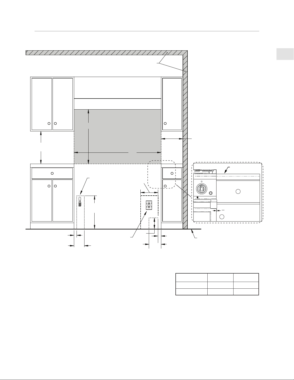
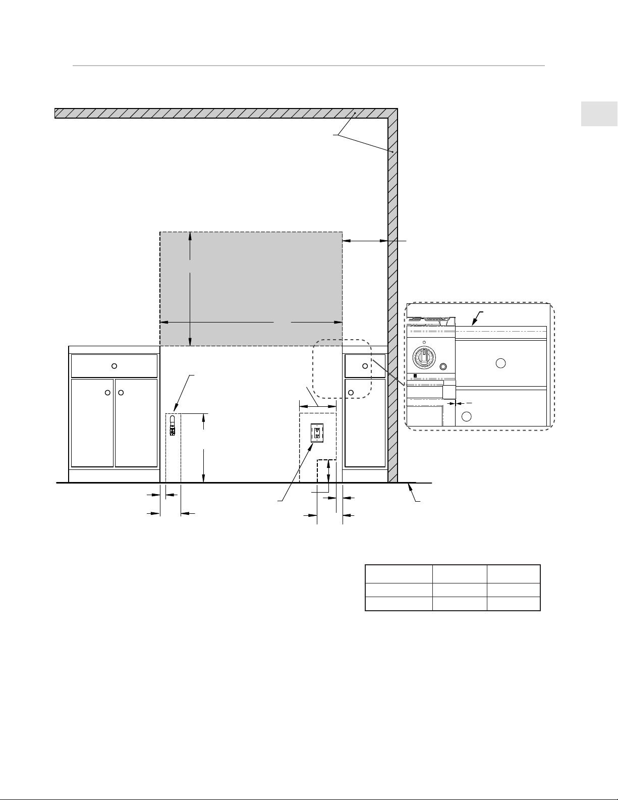
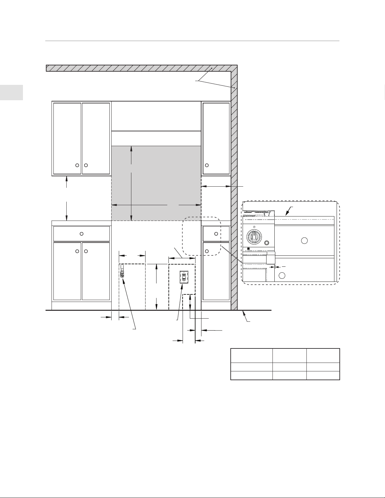
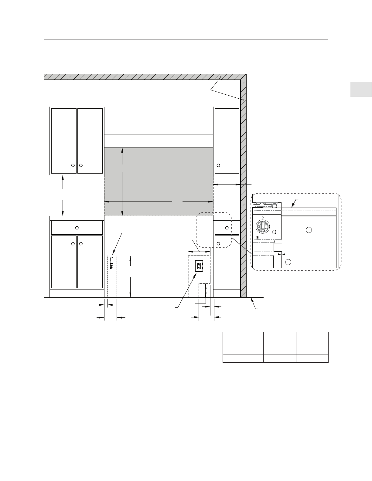
LOCATION AND INSTALLATION/VENTILATION
(CONTINUED)
W
V
6”
[15.2]
12”
[30.5]
18”
[45.7]
G
12”
[30.5]
RECOMMENDED
GAS SHUT-OFF
VALVE LOCATION
ELECTRICAL
SUPPLY
LOCATION
E
[5.1]
2”
7”
[17.8]
2”
[5.1]
INSTALLATION CLEARANCES 36” WITH LOW BACKGUARD
FRONT VIEW
VENT HOOD
MIN. CLEARANCE
TO NEAREST
COMBUSTIBLE
SIDE SURFACE
COMBUSTIBLE
MATERIALS
12”
[30.5]
FINISHED
FLOOR
DIMENSIONS IN
BRACKETS [ ] ARE
IN CM.
18” [45.7]
MIN.
COUNTERTOP
FULL OVERLAY
DRAWER FACE
FULL OVERLAY
CABINET DOOR FACE
1
8
"
[3.2 mm]
NOTES:
• SHADED AREAS INDICATE WHERE COMBUSTIBLE MATERIALS ARE NOT ALLOWED.
• APPLIANCE TOP MUST BE LEVEL OR HIGHER THAN THE ADJACENT COUNTERTOP SURFACES.
• “G” IS GAS CONNECTION ZONE ON REAR WALL. MOUNT SHUT-OFF VALVE AS HIGH AS POSSIBLE IN THIS
ZONE FOR EASY ACCESS WHEN RANGE IS INSTALLED.
• “E” IS ELECTRICAL SUPPLY ZONE.
• “W” IS APPLIANCE OPENING.
NOTE: HANDLE END CAPS PROTRUDE 1/8” BEYOND EACH SIDE OF THE RANGE. ALLOWANCE MAY BE
NEEDED FOR ADJACENT DRAWERS OR CABINETRY.
• “V” IS MIN. CLEARANCE TO REQUIRED VENTILATION HOOD.
RANGE MODEL
W V (MIN)
KRG365 36” [91.4] 30” [76.2]
KRG364GD 36” [91.4] 30” [76.2]
EN
©2020 Hestan Commercial Corporation
9
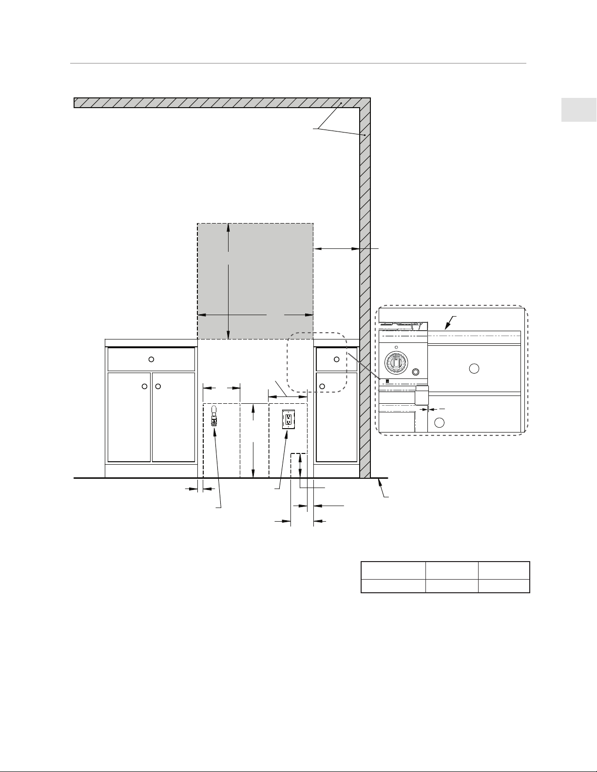
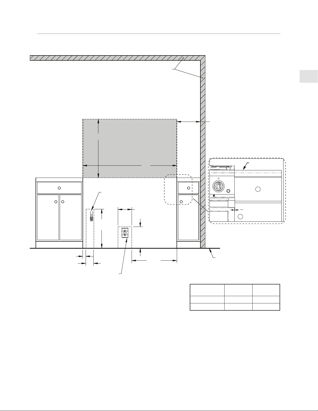
LOCATION AND INSTALLATION/VENTILATION
(CONTINUED)
NOTES:
• SHADED AREAS INDICATE WHERE COMBUSTIBLE MATERIALS ARE NOT ALLOWED.
• APPLIANCE TOP MUST BE LEVEL OR HIGHER THAN THE ADJACENT COUNTERTOP SURFACES.
• “G” IS GAS CONNECTION ZONE ON REAR WALL. MOUNT SHUT-OFF VALVE AS HIGH AS POSSIBLE IN THIS
ZONE FOR EASY ACCESS WHEN RANGE IS INSTALLED.
• “E” IS ELECTRICAL SUPPLY ZONE.
• “W” IS APPLIANCE OPENING.
NOTE: HANDLE END CAPS PROTRUDE 1/8” BEYOND EACH SIDE OF THE RANGE. ALLOWANCE MAY BE
NEEDED FOR ADJACENT DRAWERS OR CABINETRY.
• “V” IS MIN. CLEARANCE TO REQUIRED VENTILATION HOOD.
DIMENSIONS IN BRACKETS [ ] ARE IN CM.
RECOMMENDED
GAS SHUT-OFF
VALVE LOCATION
VENT HOOD
COMBUSTIBLE
MATERIALS
ELECTRICAL
SUPPLY
LOCATION
MIN. CLEARANCE
TO NEAREST
COMBUSTIBLE
SIDE SURFACE
FINISHED
FLOOR
INSTALLATION CLEARANCES WITH LOW BACKGUARD
FRONT VIEW
48"
W
V
G
COUNTERTOP
FULL OVERLAY
DRAWER FACE
FULL OVERLAY
CABINET DOOR FACE
1
8
"
[3.2 mm]
5-7/8”
[2.3]
1-3/4”
[4.4]
[45.7]
18”
18” [45.7]
MIN.
12”
[30.5]
2”
[5.1]
6”
[15.2]
6”
[15.2]
9”
[22.9]
E
RANGE MODEL
W V (MIN)
KRG485GD 48” [121,9] 30” [76,2]
KRG484GD 48” [121,9] 30” [76,2]
EN
©2020 Hestan Commercial Corporation
10
LOCATION AND INSTALLATION/VENTILATION
(CONTINUED)
FINISHED
FLOOR
38-3/8 - 36-7/8”
[97.5 - 93.7]
TO COOKING
SURFACE
48-5/16”
[122.7]
DIMENSIONS IN BRACKETS [ ] ARE IN CM.
LOCATION OF GAS
AND ELECTRICAL
ON FLOOR
ISLAND
TRIM
For Island Trim installations,
counter surface should
have a cantilever surface
meeting the rear of
the Island Trim
MIN. CLEARANCE
TO COMBUSTIBLE
SURFACES WITH
ISLAND TRIM
COMBUSTIBLE
MATERIALS
30-13/16”
[78.3]
24-11/16”
[62.7]
6”
[15.2]
3”
[7.6]
MAX.
RECESS
DEPTH
APPLIANCE
TOP
COOKING
SURFACE
7” [17.7]
2-5/8”
[6.7]
HANDLE
END CAP
REF 1.12”
[2.84 cm]
INSTALLATION CLEARANCES WITH ISLAND TRIM
SIDE VIEW
VENTILATION REQUIREMENTSVENTILATION REQUIREMENTS
A vent hood is REQUIRED above this appliance. It is strongly recommended that this appliance be
installed with a Hestan vent hood. Due to the high heat output of this range, it is very important
that the hood and ductwork installation meets local building codes and is installed by a qualified
technician.
Do not use a down-draft style ventilation system.
Do not mount a microwave oven/ventilator combination above the range. These type of units do not
have sufficient airflow to remove the high heat output of this range and were not tested with this
type of appliance.
For non-Hestan approved vent hoods, the vent hood and/or blower unit must be rated for 1 CFM [1.7
m³/hr] for every 100 BTU [.03 kW]. (See rating plate for BTU rating of your unit.)
• If the range has a 12” Griddle, add an additional 200 CFM [340 m³/hr] to the blower capacity.
EN
©2020 Hestan Commercial Corporation
11
LOCATION AND INSTALLATION/VENTILATION
(CONTINUED)
FINISHED
FLOOR
COMBUSTIBLE
MATERIALS
MIN. CLEARANCE
TO NEAREST
COMBUSTIBLE
SIDE SURFACE
W
V
DIMENSIONS IN
BRACKETS [ ] ARE
IN CM.
COUNTERTOP
FULL OVERLAY
DRAWER FACE
FULL OVERLAY
CABINET DOOR FACE
1
8
"
[3.2 mm]
INSTALLATION CLEARANCES 30” WITH ISLAND TRIM
FRONT VIEW
12"
[30.5]
18"
[45.7]
9”
[22.9]
9”
[22.9]
G
E
2”
[5.1]
2”
[5.1]
6”
6”
[15.2]
[15.2]
RECOMMENDED
GAS SHUT-OFF
VALVE LOCATION
ELECTRICAL
SUPPLY
LOCATION
RANGE MODEL
W V (MIN)
KRG304 30” [76,2] 30” [76,2]
NOTES:
• SHADED AREAS INDICATE WHERE COMBUSTIBLE MATERIALS ARE NOT ALLOWED.
• APPLIANCE TOP MUST BE LEVEL OR HIGHER THAN THE ADJACENT COUNTERTOP SURFACES.
• “G” IS GAS CONNECTION ZONE ON REAR WALL. MOUNT SHUT-OFF VALVE AS HIGH AS POSSIBLE IN THIS
ZONE FOR EASY ACCESS WHEN RANGE IS INSTALLED.
• “E” IS ELECTRICAL SUPPLY ZONE.
• “W” IS APPLIANCE OPENING.
NOTE: HANDLE END CAPS PROTRUDE 1/8” BEYOND EACH SIDE OF THE RANGE. ALLOWANCE MAY BE
NEEDED FOR ADJACENT DRAWERS OR CABINETRY.
• “V” IS MIN. CLEARANCE TO REQUIRED VENTILATION HOOD.
EN
©2020 Hestan Commercial Corporation
12
LOCATION AND INSTALLATION/VENTILATION
(CONTINUED)
COUNTERTOP
FULL OVERLAY
DRAWER FACE
FULL OVERLAY
CABINET DOOR FACE
1
8
"
[3.2 mm]
12”
[30.5]
18”
[45.7]
G
12”
[30.5]
7”
[17.8]
RECOMMENDED
GAS SHUT-OFF
VALVE LOCATION
ELECTRICAL
SUPPLY
LOCATION
E
2”
[5.1]
6”
[15.2]
2”
[5.1]
12”
[30.5]
FINISHED
FLOOR
MIN. CLEARANCE
TO NEAREST
COMBUSTIBLE
SIDE SURFACE
COMBUSTIBLE
MATERIALS
DIMENSIONS IN
BRACKETS [ ]
ARE IN CM.
INSTALLATION CLEARANCES 36” WITH ISLAND TRIM
FRONT VIEW
W
V
RANGE MODEL
W V (MIN)
KRG365 36” [91.4] 30” [76.2]
KRG364GD 36” [91.4] 30” [76.2]
NOTES:
• SHADED AREAS INDICATE WHERE COMBUSTIBLE MATERIALS ARE NOT ALLOWED.
• APPLIANCE TOP MUST BE LEVEL OR HIGHER THAN THE ADJACENT COUNTERTOP SURFACES.
• “G” IS GAS CONNECTION ZONE ON REAR WALL. MOUNT SHUT-OFF VALVE AS HIGH AS POSSIBLE IN THIS
ZONE FOR EASY ACCESS WHEN RANGE IS INSTALLED.
• “E” IS ELECTRICAL SUPPLY ZONE.
• “W” IS APPLIANCE OPENING.
NOTE: HANDLE END CAPS PROTRUDE 1/8” BEYOND EACH SIDE OF THE RANGE. ALLOWANCE MAY BE
NEEDED FOR ADJACENT DRAWERS OR CABINETRY.
• “V” IS MIN. CLEARANCE TO REQUIRED VENTILATION HOOD.
EN
©2020 Hestan Commercial Corporation
13
LOCATION AND INSTALLATION/VENTILATION
(CONTINUED)
NOTES:
• SHADED AREAS INDICATE WHERE COMBUSTIBLE MATERIALS ARE NOT ALLOWED.
• APPLIANCE TOP MUST BE LEVEL OR HIGHER THAN THE ADJACENT COUNTERTOP SURFACES.
• “G” IS GAS CONNECTION ZONE ON REAR WALL. MOUNT SHUT-OFF VALVE AS HIGH AS POSSIBLE IN THIS
ZONE FOR EASY ACCESS WHEN RANGE IS INSTALLED.
• “E” IS ELECTRICAL SUPPLY ZONE.
• “W” IS APPLIANCE OPENING.
NOTE: HANDLE END CAPS PROTRUDE 1/8” BEYOND EACH SIDE OF THE RANGE. ALLOWANCE MAY BE
NEEDED FOR ADJACENT DRAWERS OR CABINETRY.
• “V” IS MIN. CLEARANCE TO REQUIRED VENTILATION HOOD.
5-7/8”
[2.3]
1-3/4”
[4.4]
2”
[5.1]
6”
[15.2]
6”
[15.2]
9”
[22.9]
E
ELECTRICAL
SUPPLY
LOCATION
G
RECOMMENDED
GAS SHUT-OFF
VALVE LOCATION
[45.7]
18”
INSTALLATION CLEARANCES 48" WITH ISLAND TRIM
FRONT VIEW
W
V
FINISHED
FLOOR
COMBUSTIBLE
MATERIALS
MIN. CLEARANCE
TO NEAREST
COMBUSTIBLE
SIDE SURFACE
12”
[30.5]
COUNTERTOP
FULL OVERLAY
DRAWER FACE
FULL OVERLAY
CABINET DOOR FACE
1
8
"
[3.2 mm]
DIMENSIONS IN
BRACKETS [ ] ARE
IN CM.
RANGE MODEL
W V (MIN)
KRG485GD 48” [121,9] 30” [76,2]
KRG484GD 48” [121,9] 30” [76,2]
EN
©2020 Hestan Commercial Corporation
14
LOCATION AND INSTALLATION/VENTILATION
(CONTINUED)
BACKGUARD AND ACCESSORIES
CAUTION
Sheetmetal accessories such as the backguard, and areas at the rear of
the range may have sharp edges. Wear work gloves while handling and
installing these items.
BACKGUARDBACKGUARD
Your Hestan range is supplied at the factory with an Island Trim backguard. See Table 1 in the
APPENDIX section of this manual for other backguard options available from your Hestan dealer.
Selection of the appropriate backguard depends on the installation location and adjacent materials,
and the type of vent hood to be used. Installation instructions are included with the backguard
kit. A LOW OR TALL BACKGUARD IS REQUIRED WHEN INSTALLING THE RANGE AGAINST A
COMBUSTIBLE SURFACE - THE ISLAND TRIM IS NOT SUITABLE.
CAUTION
The top of the backguard serves as an exhaust for the oven when in
operation, and as an exhaust vent to remove heat from under the
cooktop section of the range as well.
• DO NOT BLOCK or obstruct the top of the backguard.
• DO NOT touch the top of the backguard during appliance operation as it may get hot. Allow
sufficient time to cool before touching or cleaning this area.
• DO NOT position plastic or other heat-sensitive items nearby which could melt or burn.
For island applications, it is recommended to use a vent hood that is 6” [15.2 cm] wider than the
appliance, to allow for 3” [7.6 cm] of overlap on the left and right of the appliance.
Keep duct runs as short and straight as possible. Elbows and transition fittings reduce airflow
efficiency. Hestan recommends keeping the duct run under 50 ft. [15.2 m].
Consult with your Hestan dealer on selecting the appropriate vent hood for your Hestan
appliance.
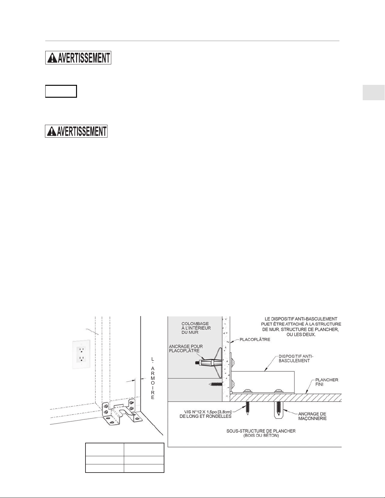
INSTALLATION OF ANTI-TIP DEVICE
THE ANTI-TIP DEVICE PROVIDED WITH THIS RANGE MUST
BE INSTALLED.
PREPARATIONPREPARATION
NOTICE
POSSIBLE PROPERTY DAMAGE - Use a qualified installer or contractor to
determine the proper method of attaching the anti-tip bracket to the rear wall or
floor behind your range. Special drills or tools may be needed to drill holes in the wall or floor
(ceramic tile, hardwood flooring, etc.).
ELECTRICAL SHOCK HAZARD - Use extreme caution when drilling holes
into the wall or floor as there may be hidden wires. Identify the electrical
circuits that could be affected by the installation of the anti-tip bracket. Shut off the power to these
circuits. Failure to follow these instructions may result in death or electrical shock.
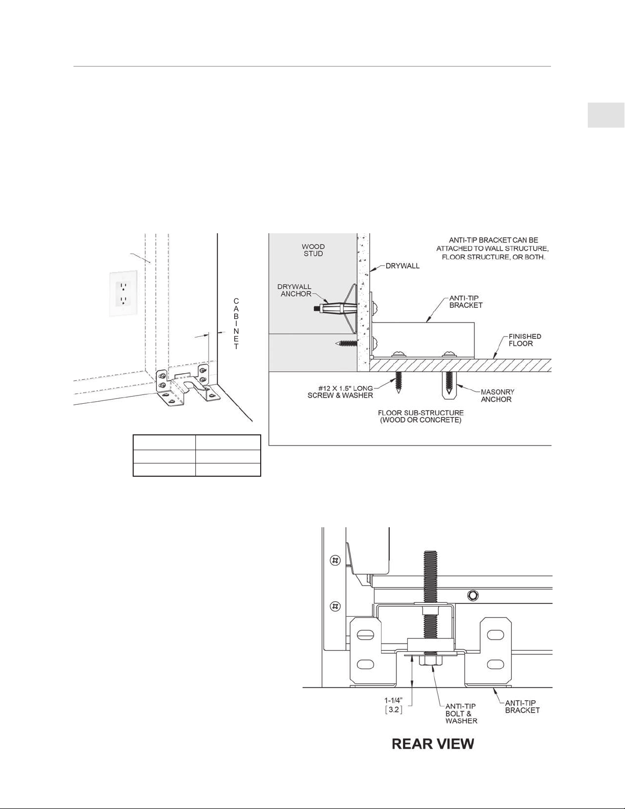
HOLE PREPARATIONHOLE PREPARATION
The anti-tip bracket must be installed in sound materials, such as wood studs in the wall AND floor
joists under the finished floor. They must be able to withstand the forces exerted on the bracket by
the range should it tip-over. If wood studs or other suitable materials are not in the designated area
behind the range, you must attach the bracket using appropriate drywall anchors or similar fasteners.
EN
©2020 Hestan Commercial Corporation
15
INSTALLATION OF ANTI-TIP DEVICE
(CONTINUED)
DRYWALL INSTALLATION: After positioning the bracket as per the diagram below, mark the holes
and drill the appropriate holes as per the instructions supplied with the wall anchors. For hardboard
or solid plaster walls, you may need different wall anchors, available at your local hardware store or
home center.
WOOD FLOOR INSTALLATION: After positioning the bracket as per the diagram below, mark the
holes and drill the appropriate holes for #12 or similar, large wood screws, at least 1.5” [3.8 cm] in
length. Use washers as well. All hardware is available at your local hardware store or home center.
CONCRETE FLOOR INSTALLATION: After positioning the bracket as per the diagram below, mark
the holes and drill the appropriate holes for #12 or similar large masonry anchors, at least 1.5” [3.8
cm] in length. Use washers as well. All hardware is available at your local hardware store or home
center.
X
WOOD STUD
INSIDE WALL
C
A
B
I
N
E
T
FLOOR
ANTI-TIP BOLT ADJUSTMENT ANTI-TIP BOLT ADJUSTMENT
After leveling the range, and after the bracket
has been attached, adjust the anti-tip bolt and
large washer under the range so the top of the
washer is 1-1/4” [3.2 cm] maximum from the
floor. Slide the range into the opening of the
bracket and verify the bolt is engaged in the
bracket as seen below. Carefully tip the range
forward to check. The range should not move
more than 1” [2.5 cm].
RANGE MODEL
X
30”, 48” 1” [2.5 cm]
36” 1-13/16” [4.6 cm]
EN
©2020 Hestan Commercial Corporation
16
ELECTRICAL CONNECTIONS
ELECTRICAL SHOCK HAZARDELECTRICAL SHOCK HAZARD
Disconnect power before installing or servicing appliance. Before turning power ON, be sure all
controls are in the OFF position. Failure to do so can result in electrical shock or death.
ELECTRICAL GROUNDING ELECTRICAL GROUNDING
This appliance must be grounded. Grounding reduces the risk of electric shock
in the event of a short circuit. Grounding through the neutral conductor is
prohibited for new branch circuit installations (1996 NEC), mobile homes, and
recreational vehicles, or in an area where local codes prohibit it. Your Hestan
range is equipped with a 3-prong, grounding type plug which must be plugged
into a grounded, 3-prong 120V receptacle.
CAUTION
Improper grounding will cause malfunctions in the unit, such as continuous sparking of the igniters.
This can damage the appliance and create a shock hazard condition.
ELECTRICAL CONNECTIONELECTRICAL CONNECTION
The receptacle must be on its own dedicated circuit - 120 VAC, Single Phase, 60 Hz, with a current
rating of 15 Amps. If this is not available, a licensed electrician must install the appropriately
dedicated and grounded receptacle. The installation must be done in accordance with local codes,
or in the absence of local codes, it must be installed in accordance with the National Electrical Code,
ANSI/NFPA 70.
1. Make sure power is off at the supply panel / breaker.
2. Plug the appliance into the wall receptacle. Secure extra appliance cord out of the way so it
cannot be snagged or pinched behind your range.
3. Before restoring power at the supply panel / breaker, be sure all controls are in the OFF position.
EN
©2020 Hestan Commercial Corporation
17
GAS SUPPLYGAS SUPPLY
The local gas authority or supplier should be consulted at the installation planning stage in order to
establish the availability of an adequate supply of gas (NG or LP). If it is a new installation, have the
gas authorities or supplier check the meter size and piping to assure that the unit is supplied with the
necessary amount of gas supply and pressure to operate the unit(s).
Gas connections should be made by a qualified plumber, or your professional appliance installer.
All appliances must be fitted with an accessible upstream gas shutoff valve as a means of isolating the
appliance for emergency shut off and for servicing.
Make certain new piping and connections have been made in a clean manner and have been purged
so that piping compound, chips, etc. will not clog regulators, valves, orifices, or burners. Use pipe
joint compound / thread sealant approved for natural and LP gases.
The appliance and its individual manual shutoff valve must be disconnected from the gas supply
piping system during any pressure testing of that system at test pressures in excess of 1/2 psi [3.5
kPa].
The appliance must be isolated from the gas supply piping system by closing its individual manual
shutoff valve during any pressure testing of that system at test pressures equal to or less than 1/2 psi
[3.5 kPa].
NEVER CONNECT THE APPLIANCE TO AN UNREGULATED GAS SUPPLY. Before proceeding,
ensure the appliance is fitted for Natural or Liquid Propane gas. Connecting to an improper gas type
will result in poor performance and increased risk of damage or injury. Gas type and gas consumption
(BTU per hour) for each burner type is shown on the rating label.
Installation of this cooking appliance must be made in accordance with local codes. In the absence of
local codes, this unit should be installed in accordance with the National Fuel Gas Code No.
Z223.1/
NFPA 54
, Natural Gas and Propane Installation code
CSA B149-1
, or Propane Storage and Handling
Code B149.2.
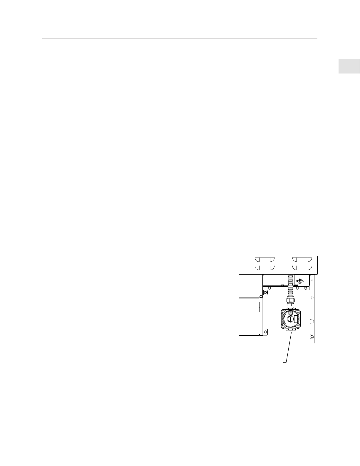
NOTE:NOTE: See rating label for manifold pressure for the type of gas of your appliance.
The gas connection at the back of the range (see below) features
1/2”NPT internal threads. Connect to gas supply using a minimum
3/4” inside diameter (1” OD) flexible (semi–rigid) stainless steel gas
hose with appropriate end fittings to prevent gas starvation. This hose
should be no more than 48” [1.2 m] in length. Use the appropriate
thread sealant on all connections. Do not apply sealant to flare
fittings.
The supply line must not interfere with the rear of the range. Use
caution when pushing the range against the back wall, so that you do
not kink or crimp the flex hose as this could result in a gas leak.
CONVERSION KITSCONVERSION KITS
In the event your Hestan appliance needs to be converted from NG to
LP, or vice-versa, you will need to contact Hestan Customer Service to
arrange a service call. This conversion should only be performed by a
qualified technician.
HIGH ALTITUDE KITSHIGH ALTITUDE KITS
If you live in a high altitude area, 2,000 ft. [610 m] or more above sea level, your appliance may
require different orifices for proper combustion and performance. You will need to contact Hestan
Customer Service to arrange a service call. High Altitude kits must be installed by a qualified
technician. Please have your model and serial number information ready when you call.
1/2”NPT
INTERNAL
GAS CONNECTION

EN
©2020 Hestan Commercial Corporation
18
GAS CONNECTION
(CONTINUED)
GAS CONNECTION - NATURAL GAS (NG)GAS CONNECTION - NATURAL GAS (NG)
To ensure proper heating performance of this appliance, verify that the gas line supply pressure is
adequate. The appliance is supplied with a gas pressure regulator already installed. This regulator
is set for a supply (inlet) pressure of 7-14 inch WC [1.74-3.48 kPa] to maintain 5 inch WC [1.24 kPa]
nominal outlet (manifold) pressure.
Ensure that the service pipe supplying the appliance is fitted with a shut-off valve conveniently
positioned and easily accessible as an emergency gas shut-off.
GAS CONNECTION - LIQUID PROPANE (LP)GAS CONNECTION - LIQUID PROPANE (LP)
If you purchased an LP version of your appliance, it will be supplied with a gas pressure regulator
already installed. This regulator is set to maintain 10 inch WC [2.49 kPa] nominal outlet (manifold)
pressure.
Ensure that the service pipe supplying the appliance is fitted with a shut-off valve conveniently
positioned and easily accessible as an emergency gas shut-off.
When connecting to LP gas, verify the tank is equipped with its own high pressure regulator. The
pressure of the gas supplied to the appliance must be 11-14 inch WC [2.74-3.48 kPa].
LEAK TESTINGLEAK TESTING
GENERALGENERAL
Although all gas connections on your Hestan appliance are leak tested at the factory prior to
shipment, a complete gas tightness check must be performed at the installation site due to possible
movement in shipment, or excessive pressure unknowingly being applied to parts of the unit.
Immediately check if the smell of gas is detected. Leak testing of the appliance shall be conducted
according to these instructions:
BEFORE TESTINGBEFORE TESTING
DO NOT SMOKE WHILE LEAK TESTING.DO NOT SMOKE WHILE LEAK TESTING.
• Never leak test with an open flame.
• Make a soap solution of one part liquid detergent and one part water for leak testing purposes.
• Apply the solution to the gas fittings and flex hose by using a spray bottle or a brush.
TO TESTTO TEST
• Make sure all control knobs are in the “OFF” position.
• Apply the soap solution to all fittings and flex hose.
• Turn the gas supply on.
• Check all connections from the supply line up to the regulator connection at the rear of the
appliance.
• Soap bubbles will appear where a leak is present. If a leak is present, immediately turn off gas
supply, tighten any leaking fittings, turn the gas supply back on, and recheck.
• If you cannot stop a gas leak, turn off the gas supply and call the dealer where you purchased
your appliance.
• Do not use the appliance until all connections have been checked and do not leak.
EN
©2020 Hestan Commercial Corporation
19
FINAL SETUP
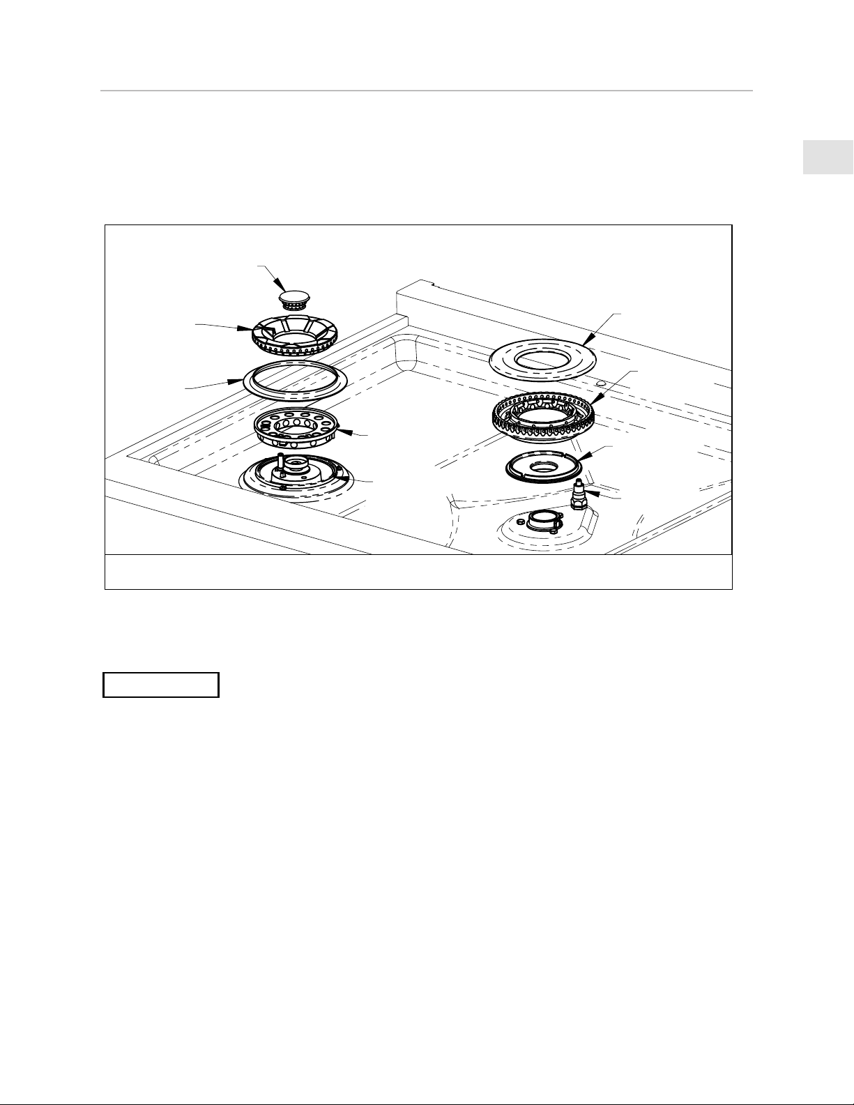
Remove any final packaging materials, and protective film from all exterior areas. Check inside oven
for other packaging items, tape on oven racks, etc. Install any loose items like sealed burner heads,
cooking grates, etc. Ensure the sealed burner heads are properly installed and seated on the burner
base as shown below. There are notches on the burner base and cross ring to help with alignment.
The outer burner head features a long slot on the top of the head which aligns with the spark igniter.
Assembly of the single-flow burner head is similar.
Before testing operation of the appliance, verify the leak check was performed and the electrical
power has been restored to the unit. Turn the gas shut-off valve to the open position.
NOTICE
All the control knobs must be in the OFF position to prevent unintended operation at power up.
In the event of a power failure, the oven will shut off. The surface burners will continue to burn,
but must be ignited manually with suitable lighter or match. When the power is restored, the oven
will not operate until the oven knobs are in the OFF position. Set all the knobs to OFF, and resume
normal use.
DO NOT ATTEMPT TO USE THE RANGE DURING A PROLONGED POWER FAILURE.
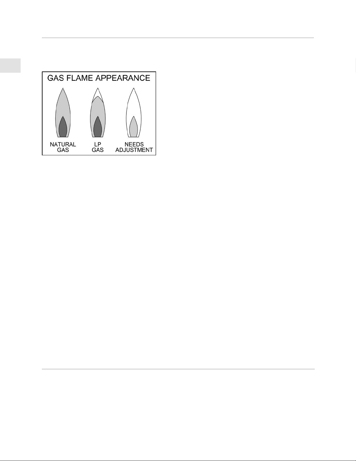
Verify ignition at each burner. Igniter will make a clicking sound until the flame lights within 4
seconds, then the clicking will stop. Check flame characteristics at each burner per the descriptions
below. Flames should be stable and not dance or lift off the burner ports. Flame may need to burn
for a few minutes to purge the gas lines of impurities. These appear as intermittent orange tips or
even tiny sparks in the flame. This is normal and the flame will eventually stabilize like those shown
in the image below.
If after a few minutes the flames continue to burn mostly yellow, verify that the burner head is
properly installed on top of the base, then retest. Use caution when handling the burner head. They
can be very hot.
BURNER
RING
BURNER
HEAD
BURNER
BASE
IGNITER
INNER
BURNER
HEAD
OUTER
BURNER
HEAD
BEAUTY
RING
CROSS
RING
BURNER
BASE
DUAL FLOW
BURNER
SINGLE FLOW
BURNER
EN
©2020 Hestan Commercial Corporation
20
SERVICE
All warranty and non-warranty repairs should be performed by qualified service personnel. To
locate an authorized service agent in your area, contact your Hestan dealer, local representative, or
Hestan. Before you call, please have the model number and serial number information on hand.
Hestan Commercial Corporation
3375 E. La Palma Avenue
Anaheim, CA 92806
(888) 905-7463
FINAL SETUP
(CONTINUED)
Turn down the control knob to the simmer setting to check function.
Check each burner individually, then check they operate satisfactorily with other burners on.
Light blue flame - Natural gas normal flame
Light blue flame with yellow tips - LP gas normal flame
Yellow flame - Needs adjustment
GAS GRIDDLEGAS GRIDDLE
The gas griddle does not have flame/burner adjustments. Turn the control knob to HIGH, verify
that the griddle heats up. You may also notice a constant orange glow at the rear vents of the
griddle area. This is normal during operation of the griddle.
Turn all burners off when testing is complete.
If after all the above tests still result in mostly yellow flames, or the burners do not light, contact
Hestan customer service to schedule a service call.
OVEN OPERATIONOVEN OPERATION
All rangetop checks to be performed prior to oven operation check.
Open and close oven door to check oven lights illuminate on opening, and fade once closed. Cycle
oven lights using control panel switch to validate proper function.
With the door open, set mode knob to BAKE and temperature knob to 350°F. Both knob backlights
will illuminate and the orange “heating” indicator light will turn on. Bake igniter (located below
bottom drip pan) begins to glow and once it reaches proper temperature, the gas valve is energized.
Verify ignition and flame characteristics of bake burner.
Close the oven door. Set mode knob and temperature knob to BROIL. Both knob backlights will
illuminate and the orange “heating” indicator light will turn on. Broil igniter (located at top of oven
cavity) begins to glow and once it reaches proper temperature, the gas valve is energized. Verify
ignition and flame characteristics of broil burner.
Turn oven off.
NOTE: A small amount of smoke and odor may be noticed during this test, and during the initial
break-in period.
EN
©2020 Hestan Commercial Corporation
21
APPENDIX
TABLE 1: BACKGUARD OPTIONSTABLE 1: BACKGUARD OPTIONS
RANGE MODELRANGE MODEL BACKGUARD MODELBACKGUARD MODEL DESCRIPTIONDESCRIPTION
KRG304 KBGIT30* BACKGUARD, ISLAND TRIM, 30” *
KBGLB30 BACKGUARD, LOW BACK, 30”
KBGHS30 BACKGUARD, HIGH SHELF, 30”
KRG364GD KBGIT36* BACKGUARD, ISLAND TRIM, 36” *
KBGLB36 BACKGUARD, LOW BACK, 36”
KBGHS36 BACKGUARD, HIGH SHELF, 36”
KRG364GD KBGIT36* BACKGUARD, ISLAND TRIM, 36” *
KBGLB36 BACKGUARD, LOW BACK, 36”
KBGHS36 BACKGUARD, HIGH SHELF, 36”
KRG485GD KBGIT48* BACKGUARD, ISLAND TRIM, 48” *
KBGLB48 BACKGUARD, LOW BACK, 48”
KBGHS48 BACKGUARD, HIGH SHELF, 48”
KRG484GD KBGIT48* BACKGUARD, ISLAND TRIM, 48” *
KBGLB48 BACKGUARD, LOW BACK, 48”
KBGHS48 BACKGUARD, HIGH SHELF, 48”
* INCLUDED WITH RANGE
DÉFINITIONS DE SÉCURITÉ
CECI INDIQUE QUE L’INOBSERVATION DE CET AVERTISSEMENT
PEUT ENTRAÎNER DES BLESSURES GRAVES VOIRE MORTELLES.
CECI INDIQUE QUE L’INOBSERVATION DE CET AVERTISSEMENT
PEUT ENTRAÎNER DES BLESSURES MINEURES OU MODÉRÉES.
CECI INDIQUE QUE L’INOBSERVATION DE CET AVERTISSEMENT
PEUT ENTRAÎNER DES DOMMAGES DE L’APPAREIL OU DES
DÉGÂTS MATÉRIELS.
LISEZ ATTENTIVEMENT ET COMPLÈTEMENT CES INSTRUCTIONS AVANT
D’INSTALLER OU D’UTILISER VOTRE APPAREIL AFIN DE RÉDUIRE LES RISQUES
D’INCENDIE, DE BRÛLURE OU D’AUTRES BLESSURES. CONSERVER CE MANUEL
POUR RÉFÉRENCE FUTURE.
PRÉCAUTION
AVIS
INSTALLATEUR: LAISSER CE MANUEL AVEC LE PROPRIÉTAIRE DE L’APPAREIL.
PROPRIÉTAIRE: CONSERVEZ CE MANUEL POUR RÉFÉRENCE FUTURE.
Ne pas entreposer ou utiliser d’essence ou tout autre liquide ou gaz inflammable à proximité de
cet appareil ou de tout autre appareil.
EN PRÉSENCE D’UNE ODEUR DE GAZ:EN PRÉSENCE D’UNE ODEUR DE GAZ:
1. Ne tenter d’allumer aucun appareil.
2. Ne toucher à aucun commutateur électrique.
3. N’utiliser aucun téléphone dans l’immeuble.
4. Appeler immédiatement le fournisseur de gazà partir d’un téléphone situé à l’extérieur
del’immeuble ; Suivre les instructions dufournisseur de gaz.
5. S’il est impossible de joindre le fournisseur degaz, appeler le service des incendies.
L ’installation et la réparation doivent être effectuées par un installateur ou une agence deréparation
ayant les qualifications requises oupar le fournisseur de gaz.
LE NON-RESPECT À LA LETTRE DE CES INSTRUCTIONS PEUT CAUSER
UN INCENDIE OU UNE EXPLOSION, QUI POURRAIT ENTRAÎNER DES
DOMMAGES MATÉRIELS, DES BLESSURES OU LA MORT.
DANGER DE BASCULEMENTDANGER DE BASCULEMENT
Une personne, enfant ou adulte, peut faire basculer la cuisinière et subir des
blessures mortelles.
Vérifiez l’installation du dispositif anti-basculement conformément aux instructions
d’installation.
Ne pas utiliser la cuisinière lorsque le dispositif n’est pas installé et engagé.
Vérifiez l’engagement du dispositif anti-basculement si la cuisinière est déplacée, par exemple quand vous
nettoyez derrière elle.
Pour vérifier l’engagement, inclinez doucement la cuisinière vers l’avant tout en tirant de l’arrière de
l’appareil. La cuisinière ne doit pas bouger de plus de 1 po [2,5 cm].
Le non-respect de ces instructions peut entraîner la mort ou des brûlures graves chez les enfants et les
adultes.
Pour réduire le risque de brûlure, ne déplacez pas cet appareil lorsqu’il est chaud.
1
FR
©2020 Hestan Commercial Corporation
S’il est bien entretenu, cet appareil Hestan procurera un service sûr et fiable pendant de nombreuses
années. Lorsqu’on se sert de cet appareil, les pratiques élémentaires suivantes en matière de sécurité
doivent être adoptées.
IMPORTANT: Conservez ces instructions à l’intention de l’Inspecteur local des services du gaz ou de
l’électricité.
INSTALLATEUR: Veuillez laisser ces instructions d’installation au propriétaire.
PROPRIÉTAIRE: Veuillez conserver ces instructions d’installation pour référence future.
Cette cuisinière N’EST PAS conçue pour être installée dans des maisons préfabriquées (mobiles) ou dans
des véhicules récréatifs. N’installez PAS cette cuisinière à l’extérieur.
PRÉCAUTIONS DE SÉCURITÉ - AVANT DE COMMENCER
RISQUE DE CHOC ÉLECTRIQUERISQUE DE CHOC ÉLECTRIQUE
Débranchez l’alimentation avant d’installer ou d’entretenir l’appareil. Avant de
le mettre sous tension, assurez-vous que toutes les commandes sont en position
«OFF». Ne pas le faire peut entraîner un choc électrique ou la mort.
MISE À LA TERRE ÉLECTRIQUEMISE À LA TERRE ÉLECTRIQUE
Cet appareil doit être mis à la terre. La mise à la terre réduit le risque de
choc électrique en cas de court-circuit. Lisez la section BRANCHEMENTS
ÉLECTRIQUES de ce manuel pour des instructions complètes.
Cet appareil est pourvu d’une fiche à trois broches don’t une mise à la terre
assurant une protection contre les chocs électriques. La prise dans laaquelle elle est branchée doit être
correctement mise à la terre. Ne pas couper ni enlever la broche de mise à la terre de la fiche.
ALIMENTATION ÉLECTRIQUEALIMENTATION ÉLECTRIQUE
L’appareil doit avoir son propre circuit distinct - 120 VAC, monophasé, 60 Hz, avec une ampérage
nominale telle qu’indiquée dans la liste des numéros de modèle à la page 2. Demandez à l’installateur de
vous montrer où se trouve le disjoncteur électrique afin de savoir comment couper l’alimentation de cet
appareil. Il incombe à l’utilisateur de faire raccorder l’appareil par un électricien agréé conformément à
tous les codes locaux, ou en l’absence de ces codes, conformément au Code National de l’Électricité. Lisez
la section BRANCHEMENTS ÉLECTRIQUES du cet manuel pour tous le détails.
TABLE DES MATIÈRES
1 PRÉCAUTIONS DE SÉCURITÉ - AVANT DE COMMENCER
2 NUMÉROS DE MODÈLE
3 PLAQUE SIGNALÉTIQUE
3 RESPECT DE LA RÉGLEMENTATION ET DES CODES EN VIGUEUR
3 EMPLACEMENT ET INSTALLATION / VENTILATION
14 DOSSERET ET ACCESSOIRES
15 INSTALLATION DU DISPOSITIF ANTI-BASCULEMENT
17 BRANCHEMENTS ÉLECTRIQUES
18 RACCORDEMENT DE GAZ
20 PHASE FINALE DE L’INSTALLATION
21 SERVICE
22 APPENDICE
2
FR
©2020 Hestan Commercial Corporation
NUMÉROS DE MODÈLE
MODÈLES DE CUISINIÈREMODÈLES DE CUISINIÈRE
NO. MODÈLENO. MODÈLE DESCRIPTIONDESCRIPTION
DISJONCTEUR DISJONCTEUR
REQUISREQUIS
KRG304-NG / -LP CUISINIÈRE À GAZ 36 PO A 4 BRÛLEURS 15 Ampères
KRG365-NG / -LP CUISINIÈRE À GAZ 36 PO A 5 BRÛLEURS 15 Ampères
KRG364GD-NG / -LP CUISINIÈRE À GAZ 36 PO A 4 BRÛLEURS ET PLAQUE CHAUFFANTE 15 Ampères
KRG485GD-NG / -LP CUISINIÈRE À GAZ 48 PO A 5 BRÛLEURS ET PLAQUE CHAUFFANTE 12 PO 15 Ampères
KRG484GD-NG / -LP CUISINIÈRE À GAZ 48 PO A 4 BRÛLEURS ET PLAQUE CHAUFFANTE 24 PO 15 Ampères
KRG365KRG365
KRG304KRG304
KRG485GDKRG485GD
KRG484GDKRG484GDKRG364GDKRG364GD
3
FR
©2020 Hestan Commercial Corporation
L’installation de cet appareil de cuisson doit être effectuée conformément aux codes locaux. En l’absence
de tels codes, installer cet appareil conformément au National Fuel Gas Code ANSI Z223.1/NFPA 54, au
code Natural Gas and Propane Installation CSA B149.1 ou au Propane Storage and Handling Code B149.2.
Tous les composants électriques doivent mis à la terre conformément aux codes locaux ou, en l’absence
de tels codes, au National Electrical Code ANSI/NFPA 70 ou au Code national de l’électricité du Canada
CSAC22.1.
COMMUNAUTÉ DU MASSACHUSETTSCOMMUNAUTÉ DU MASSACHUSETTS
Le Communauté du Massachusetts exige que toutes les installations au gaz soient effectuées par
un plombier ou monteur d’installations au gaz titulaire d’une autorisation appropriée délivrée par le
Massachusetts. Toutes les installations à demeure fonctionnant au propane ou au gaz naturel exigent la
pose d’un robinet manuel de gaz à poignée en T sur la conduite d’alimentation en gaz de l’appareil. Le
tuyau de raccordement flexible de gaz ne doit pas dépasser 48 po [1,2 m].
PROPOSITION 65 DE CALIFORNIE – MISE EN GARDEPROPOSITION 65 DE CALIFORNIE – MISE EN GARDE
AVERTISSEMENT:AVERTISSEMENT: Ce produit peut vous exposer à des produits chimiques, notamment du
monoxyde de carbone, reconnu par l’État de Californie pour causer des malformations
congénitales ou d’autres problèmes de reproduction.
Pour plus d’informations, visitez www.P65Warnings.ca.gov.
PLAQUE
SIGNALÉTIQUE
PLAQUE SIGNALÉTIQUE
La plaque signalétique donne des informations importantes sur
cet appareil Hestan telles que les numéros de série et de modèle,
le type de gaz et la pression d’admission, les caractéristiques
électriques, la cote BTU pour chaque type de brûleur et les
dégagements minima d’installation.
La plaque signalétique se trouve sur le côté droit de l’ouverture de
la cavité du four près de la charnière de la porte.
Si un entretien est nécessaire, contactez le service clientèle de
Hestan avec les informations sur le modèle et le numéro de série
figurant sur la plaque.
DÉBALLAGE ET PLACEMENTDÉBALLAGE ET PLACEMENT
Retirez le carton extérieur et les matériaux d’emballage de la palette d’expédition. Ne retirez pas le film
plastique recouvrant les surfaces en acier inoxydable. Ce film protège la finition contre les rayures jusqu’à
ce que l’appareil soit installé dans sa position finale.
L’unité est très lourde et doit être manipulée avec soin. Utilisez un équipement de sécurité approprié, tel
que des gants, et au moins 2 personnes pour mettre l’appareil en position pour éviter les blessures et éviter
d’endommager le sol ou l’appareil lui-même.
AVIS
N’UTILISEZ PAS DE CHARIOT À BRAS À L’AVANT OU À L’ARRIÈRE DE LA CUISINIÈRE.
MANIPULER ET DÉPLACER DEPUIS LES CÔTÉS.
Ne soulevez ou ne portez pas l’appareil en le tenant par la porte ou la poignée du four. Cela pourrait
endommager les charnières de la porte.
La cuisinière est maintenue sur la palette avec 4 grands boulons d’expédition des deux côtés. Retirez ces
boulons, puis déplacez la cuisinière au sol avec l’aide de 2 personnes.
EMPLACEMENT ET INSTALLATION / VENTILATION
RESPECT DE LA RÉGLEMENTATION ET DES CODES EN VIGUEUR
4
FR
©2020 Hestan Commercial Corporation
EMPLACEMENT ET INSTALLATION / VENTILATION
(SUITE)
PRÉPARATIONPRÉPARATION
Avant de déplacer la cuisinière, protégez tout revêtement de sol fini et fermez la(les) porte(s) du four afin
qu’elle(s) ne soi(en)t pas endommagée(s).
DÉGAGEMENTS DE GAZ ET D’APPROVISIONNEMENT ÉLECTRIQUEDÉGAGEMENTS DE GAZ ET D’APPROVISIONNEMENT ÉLECTRIQUE
Si ce n’est pas déjà fait, posez un robinet d’arrêt de gaz dans un endroit facilement accessible pour
l’entretien de la cuisinière. Assurez-vous que tous les utilisateurs de la cuisinière savent où se trouve cette
fermeture et comment couper le gaz. Toute ouverture dans le mur ou le plancher derrière l’appareil doit
être scellée. Les dégagements d’installation sur les pages suivantes indiquent où les zones « G » et « E »
doivent être situées.
La cuisinière est conçue pour être installée près du
mur arrière*. Il peut être nécessaire de repositionner
l’alimentation en gaz et le réceptacle d’alimentation /
boîte de connexion afin d’accommoder la cuisinière
lorsqu’elle est repoussée contre le mur.
L’arrière de la cuisinière est encastré de 3-1/4 po [8,3 cm]
pour laisser de la place au cordon et au tuyau de gaz. Si
vous utilisez une boîte de jonction / prise murale, vous
devrez peut-être la monter pour diriger le cordon le long
du mur plutôt que vers la cuisinière.
* Sauf si installé dans une île sans mur arrière.
ALIMENTATION
EN GAZ
VERS L'APPAREIL
ROBINET D’ARRÊT EN
POSITION OUVERTE
3-1/4 po [8,3 cm] max.
mur à l'arrière de la
cuisinière
boîte montée
contre le mur
pour diriger le
cordon le long
du mur
Broche de terre
Réceptacle à
3 broches
Boîte de prise de terre
Conduit
ARMOIRESARMOIRES
Pour éliminer le risque de brûlures ou d’incendie lorsqu’on se penche au-dessus des unités de surface
chauffées, il convient d’éviter d’utiliser l’espace de rangement offert par les armoires situés au-dessus des
unités de surface. Si on doit prévoir un espace de rangement, le risque peut être réduit en installant la
hotte d’évacuation requise de façon à ce qu’elle dépasse horizontalement d’au moins 5 po [12,7 cm] du
fond des armoires.
5
FR
©2020 Hestan Commercial Corporation
EMPLACEMENT ET INSTALLATION / VENTILATION
(SUITE)
RÉINSTALLATION DE LA PORTE DU FOURRÉINSTALLATION DE LA PORTE DU FOUR
1. Tenez fermement la porte des deux côtés (PAS PAR LA POIGNÉE) à environ 30° de la position fermée
et insérez les charnières dans les fentes du four. Le bord inférieur de chaque charnière comporte une
encoche qui doit se loger à l’intérieur de l’ouverture de la fente. NE PAS FORCER, COURBER NI
GAUCHIR LA PORTE! [ E & F ]
2. Ouvrez lentement la porte complètement. Faites pivoter les griffes à charnières à l’opposé de vous
jusqu’à ce qu’elles soient complètement à l’intérieur de l’ouverture de la fente et complètement
insérées. Un tournevis peut vous aider à le faire. [ G ]
3. Fermez doucement la porte du four pour vérifier son bon fonctionnement.
Griffe à
charnière
A
B
Griffe à
charnière
C
F
G
H
Griffe à
charnière
RETRAIT DE LA PORTE DU FOURRETRAIT DE LA PORTE DU FOUR
Si vous avez une porte très étroite s’ouvrant sur votre cuisine, la(les) porte(s) du four peu(ven)t être
enlevée(s). NE RETIRER QUE SI ABSOLUMENT NÉCESSAIRE. Le retrait de la ou des portes ne doit
être effectué que par un installateur ou un technicien de maintenance agréé. Assurez-vous que le four
est complètement refroidi et que l’alimentation électrique est coupée. Ne pas le faire peut provoquer un
choc électrique ou une brûlure. Faites attention en enlevant la porte, car elle est très lourd.
1. Ouvrez la porte du four complètement.
2. À chaque emplacement de charnière, faites pivoter le griffe de charnière vers l’avant jusqu’à ce qu’il
s’arrête. Un tournevis peut être nécessaire pour ce faire. [ B ]
3. Fermez doucement la porte du four jusqu’à ce qu’elle s’arrête contre les griffes à charnières, ou à
environ 30° de la position fermée. Tenez fermement les deux côtés de la porte (pas la poignée) et tirez
la porte droit vers le haut pour la séparer des charnières. Placez la porte du four dans un endroit sûr
jusqu’à ce que vous en ayez besoin. NE JAMAIS relâcher les griffes à charnières et essayer de fermer
les charnières. Cela fermera les charnières avec une grande force, ce qui pourrait causer des blessures.
[ C & D ]
6
FR
©2020 Hestan Commercial Corporation
EMPLACEMENT ET INSTALLATION / VENTILATION
(SUITE)
DÉGAGEMENTS D'INSTALLATION AVEC DOSSERET BAS
VUE DE CÔTÉ
PLANCHER FINI
7 po [17,7]
2-5/8 po
[6,7]
REF 1,12 po
[2,84]
po61/31-03
[78,3]
po61/11-42
[62,7]
13 po [33]
MAX.
DOSSERET BAS
PROFONDEUR
MAX. DU
RENFONCEMENT
SURFACE
DE
CUISSON
HAUT DE
L'APPAREIL
MATÉRIAUX
COMBUSTIBLES
36-7/8 - 38-3/8 po
[93,7 - 97,5]
À LA SURFACE
DE CUISSON
48-5/16 po
3 po
[7,6]
EMPLACEMENT DE
L'ALIMENTATION EN
GAZ ET ÉLECTRICITÉ
SUR LE PLANCHER.
LES DIMENSIONS ENTRE CROCHETS [ ]
SON EN CM.
[122,7]
FIN DE LA
POIGNÉE
HOTTE
NIVELLEMENTNIVELLEMENT
La cuisinière doit être de niveau, en particulier les modèles comportant une plaque chauffante. Soulevez
ou abaissez la cuisinière à la hauteur désirée en ajustant les quatre pieds de mise de niveau sous la
cuisinière (les unités de 48 po ont 6 pieds). Les pieds peuvent être tournées à la main. Il peut être
nécessaire d’utiliser un levier ou un autre dispositif de levage pour aider à soulever temporairement l’unité
pour tourner les pieds. Ne pas soulever ou tirer le levier depuis l’avant ou l’arrière, uniquement depuis les
côtés.
PRÉCAUTION
Le dessus de l’appareil doit être au même niveau ou plus haut que les surfaces des plans de travail
contigus. Le fait de ne pas ajuster la hauteur peut exposer les armoires contigus à une chaleur excessive
qui pourrait endommager les
armoires ou le plan de travail.
7
FR
©2020 Hestan Commercial Corporation
EMPLACEMENT ET INSTALLATION / VENTILATION
(SUITE)
PLANCHER
FINI
HOTTE DE VENTILATION
MATÉRIAUX
COMBUSTIBLES
DÉGAGEMENT MIN. PAR
RAPPORT À LA SURFACE
LATÉRALE COMBUSTIBLE
LA PLUS PROCHE
W
V
LES DIMENSIONS
ENTRE CROCHETS
[ ] SON EN CM.
1
8
po
[3.2 mm]
COMPTOIR
FACE DU TIROIR
RECOUVERTE
FACE DU PORTE
RECOUVERTE
18"
[45,7]
9”
[22,9]
9”
[22,9]
G
E
2”
[5,1]
2”
[5,1]
6”
6”
[15,2]
[15,2]
EMPLACEMENT
RECOMMANDÉ
DU
ROBINET D'ARRÊT DE GAZ
ALIMENTATION
ÉLECTRIQUE
DÉGAGEMENTS D'INSTALLATION 30 PO AVEC DOSSERET BAS
VUE DE FACE
18 po [45,7]
MIN.
12 po
[30,5]
MODÈLE DE
CUISINIÈRE
W V (MIN)
KRG304 30 po [76,2] 30 po [76,2]
REMARQUES:
• LES ZONES OMBRÉES INDIQUENT LES ENDROITS OÙ LES MATÉRIAUX COMBUSTIBLES SON PROHIBÉS.
• LE DESSUS DE L’APPAREIL DOIT ÊTRE AU MÉME NIVEAU OU PLUS HAUT QUE LES SURFACES DES PLANS DE
TRAVAIL CONTIGUS.
• «G» INDIQUE LA ZONE DE RACCORDEMENT DE GAZ SUR LE MUR ARRIÈRE.
MONTER LE ROBINET D’ARRÊT AUSSI HAUT QUE POSSIBLE DANS CETTE ZONE POUR EN FACILITER L’ACCÈS
QUAND LA CUISINIÈRE EST EN PLACE.
• «E» EST LA ZONE D’ALIMENTATION ÉLECTRIQUE.
• «W» INDIQUE L’OUVERTURE DESTINÉE À L’APPAREIL. REMARQUE: LA FIN DE LA POIGNÉE S’ÉTEND DE
1/8 PO [3,2 MM] AU-DELÀ DE CHAQUE CÔTÉ DE L’APPAREIL. IL PEUT ÊTRE NÉCESSAIRE DE FOURNIR UNE
ADAPTATION À DES TIROIRS OU DES ARMOIRES ADJACENTS.
• «V» INDIQUE LE DÉGAGEMENT MIN. PAR RAPPORT À LA HOTTE DE VENTILATION REQUISE.
8
FR
©2020 Hestan Commercial Corporation
EMPLACEMENT ET INSTALLATION / VENTILATION
(SUITE)
REMARQUES:
• LES ZONES OMBRÉES INDIQUENT LES ENDROITS OÙ LES MATÉRIAUX COMBUSTIBLES SON PROHIBÉS.
• LE DESSUS DE L’APPAREIL DOIT ÊTRE AU MÉME NIVEAU OU PLUS HAUT QUE LES SURFACES DES PLANS DE
TRAVAIL CONTIGUS.
• «G» INDIQUE LA ZONE DE RACCORDEMENT DE GAZ SUR LE MUR ARRIÈRE.
MONTER LE ROBINET D’ARRÊT AUSSI HAUT QUE POSSIBLE DANS CETTE ZONE POUR EN FACILITER L’ACCÈS
QUAND LA CUISINIÈRE EST EN PLACE.
• «E» EST LA ZONE D’ALIMENTATION ÉLECTRIQUE.
• «W» INDIQUE L’OUVERTURE DESTINÉE À L’APPAREIL.
REMARQUE: LA FIN DE LA POIGNÉE S’ÉTEND DE
1/8 PO [3,2 MM] AU-DELÀ DE CHAQUE CÔTÉ DE L’APPAREIL. IL PEUT ÊTRE NÉCESSAIRE DE FOURNIR UNE
ADAPTATION À DES TIROIRS OU DES ARMOIRES ADJACENTS.
• «V» INDIQUE LE DÉGAGEMENT MIN. PAR RAPPORT À LA HOTTE DE VENTILATION REQUISE.
11 po
[28]
18 po
[45,7]
G
11 po
[28]
5 po
[15,2]
E
2-1/2 po
[6,4]
6 po
[15,2]
3 po
[7,6]
EMPLACEMENT
RECOMMANDÉ
DU
ROBINET D'ARRÊT DE GAZ
ALIMENTATION
ÉLECTRIQUE
1
8
po
[3.2 mm]
COMPTOIR
FACE DU TIROIR
RECOUVERTE
FACE DU PORTE
RECOUVERTE
PLANCHER
FINI
LES DIMENSIONS ENTRE
CROCHETS [ ] SON EN CM.
12 po
[30,5]
18 po
HOTTE DE VENTILATION
[45,7]
MATÉRIAUX
COMBUSTIBLES
DÉGAGEMENT MIN.
PAR RAPPORT À LA
SURFACE LATÉRALE
COMBUSTIBLE LA
PLUS PROCHE
VUE DE FACE
DÉGAGEMENTS D'INSTALLATION 36 PO AVEC DOSSERET BAS
W
V
MODÈLE DE
CUISINIÈRE
W V (MIN)
KRG365 36 po [91,4] 30 po [76,2]
KRG364GD 36 po [91,4] 30 po [76,2]
9
FR
©2020 Hestan Commercial Corporation
EMPLACEMENT ET INSTALLATION / VENTILATION
(SUITE)
REMARQUES:
• LES ZONES OMBRÉES INDIQUENT LES ENDROITS OÙ LES MATÉRIAUX COMBUSTIBLES SON PROHIBÉS.
• LE DESSUS DE L’APPAREIL DOIT ÊTRE AU MÉME NIVEAU OU PLUS HAUT QUE LES SURFACES DES PLANS DE
TRAVAIL CONTIGUS.
• «G» INDIQUE LA ZONE DE RACCORDEMENT DE GAZ SUR LE MUR ARRIÈRE.
MONTER LE ROBINET D’ARRÊT AUSSI HAUT QUE POSSIBLE DANS CETTE ZONE POUR EN FACILITER L’ACCÈS
QUAND LA CUISINIÈRE EST EN PLACE.
• «E» EST LA ZONE D’ALIMENTATION ÉLECTRIQUE.
• «W» INDIQUE L’OUVERTURE DESTINÉE À L’APPAREIL.
REMARQUE: LA FIN DE LA POIGNÉE S’ÉTEND DE
1/8 PO [3,2 MM] AU-DELÀ DE CHAQUE CÔTÉ DE L’APPAREIL. IL PEUT ÊTRE NÉCESSAIRE DE FOURNIR UNE
ADAPTATION À DES TIROIRS OU DES ARMOIRES ADJACENTS.
• «V» INDIQUE LE DÉGAGEMENT MIN. PAR RAPPORT À LA HOTTE DE VENTILATION REQUISE.
G
1
8
po
[3.2 mm]
COMPTOIR
FACE DU TIROIR
RECOUVERTE
FACE DU PORTE
RECOUVERTE
ALIMENTATION
ÉLECTRIQUE
EMPLACEMENT
RECOMMANDÉ DU
ROBINET D’ARRET
DE GAZ
PLANCHER
FINI
MATÉRIAUX
COMBUSTIBLE
LES DIMENSIONS ENTRE
CROCHETS [ ] SON EN CM.
7 po
[17,8]
12 po
[30,5]
4 po
[10,2]
1-1/2 po
[3,8]
11 po
[27,9]
23 po
[58,4]
DÉGAGEMENT MIN.
PAR RAPPORT À LA
SURFACE LATÉRALE
COMBUSTIBLE LA
PLUS PROCHE
[45,7]
18 po
DÉGAGEMENTS D'INSTALLATION 48 PO AVEC DOSSERET
PROFILÉ POUR ÎLOT
VUE DE FACE
E
W
V
MODÈLE DE
CUISINIÈRE
W V (MIN)
KRG485GD 48 po [121,9] 30 po [76,2]
KRG484GD 48 po [121,9] 30 po [76,2]
10
FR
©2020 Hestan Commercial Corporation
EMPLACEMENT ET INSTALLATION / VENTILATION
(SUITE)
PLANCHER
FINI
36-7/8 - 38-3/8 po
[93,7 - 97,5]
À LA SURFACE
DE CUISSON
EMPLACEMENT DE
L'ALIMENTATION EN
GAZ ET ÉLECTRICITÉ
SUR LE PLANCHER.
DOSSERET PROFILÉ
POUR ÎLOT
Pour les installations avec
dosseret profilé pour îlot, la
surface du plan de travail doit
avoir un porte-à-faux se
jiognant a l'arrière du profilé.
DÉGAGEMENT MIN. PAR
RAPPORT AUX SURFACES
COMBUSTIBLES AVEC
DOSSERET PROFILÉ
POUR ÎLOT.
MATÉRIAUX
COMBUSTIBLES
LES DIMENSIONS
ENTRE CROCHETS [ ]
SON EN CM.
48-5/16 po
[122,7]
24-11/16 po
[62,7]
PROFONDEUR
MAX. DU
RENFONCEMENT
3 po
[7,6]
7 po [17,7]
2-5/8 po
[6,7]
po61/31-03
[78,3]
FIN DE LA
POIGNÉE
REF 1,12 po
[2,84 cm]
SURFACE
DE
CUISSON
HAUT DE
L'APPAREIL
DÉGAGEMENTS D'INSTALLATION AVEC DOSSERET PROFILÉ POUR ÎLOT
VUE DE CÔTÉ
6 po
[15,2]
EXIGENCES DE VENTILATIONEXIGENCES DE VENTILATION
Une hotte de ventilation est REQUISE au-dessus de cet appareil. Il est fortement recommandé d’installer
cet appareil avec une hotte Hestan. En raison de la puissance calorifique élevée de cette cuisinière, il est
très important que l’installation de la hotte et des conduits réponde aux codes de construction locaux et
soit réalisée par un technicien qualifié.
N’utilisez pas de système de ventilation à tirage descendant.
Ne montez pas un ensemble four à micro-ondes / ventilateur au-dessus de la cuisinière. Ces types d’unités
n’offrent pas d’un débit d’air suffisant pour évacuer la chaleur élevée de cette cuisinière et n’ont pas été
testés avec ce type d’appareil.
Pour les hottes d’évacuation non approuvées par Hestan, la hotte de ventilation et / ou la soufflante
doivent avoir une capacité nominale de 1 pi³/min [1,7 m³/h] pour chaque 100 BTU [0,03 kW] de la
cuisinière. (Voir la plaque signalétique pour l’évaluation en BTU de votre appareil.)
• Si la cuisinière est équipée d’une plaque chauffante de 12 po [30,5 cm], ajoutez 200 pi³/min
supplémentaires [340 m³/h] à la capacité de la soufflante.

11
FR
©2020 Hestan Commercial Corporation
EMPLACEMENT ET INSTALLATION / VENTILATION
(SUITE)
PLANCHER
FINI
MATÉRIAUX
COMBUSTIBLES
DÉGAGEMENT MIN. PAR
RAPPORT À LA SURFACE
LATÉRALE COMBUSTIBLE
LA PLUS PROCHE
W
V
LES DIMENSIONS
ENTRE CROCHETS [ ]
SON EN CM.
1
8
po
[3.2 mm]
COMPTOIR
FACE DU TIROIR
RECOUVERTE
FACE DU PORTE
RECOUVERTE
18"
[45,7]
9”
[22,9]
9”
[22,9]
G
E
2”
[5,1]
2”
[5,1]
6”
6”
[15,2]
[15,2]
EMPLACEMENT
RECOMMANDÉ
DU
ROBINET D'ARRÊT DE GAZ
ALIMENTATION
ÉLECTRIQUE
DÉGAGEMENTS D'INSTALLATION 30 PO AVEC DOSSERET
PROFILÉ POUR ÎLOT
VUE DE FACE
12 po
[30,5]
MODÈLE DE
CUISINIÈRE
W V (MIN)
KRG304 30 po [76,2] 30 po [76,2]
REMARQUES:
• LES ZONES OMBRÉES INDIQUENT LES ENDROITS OÙ LES MATÉRIAUX COMBUSTIBLES SON PROHIBÉS.
• LE DESSUS DE L’APPAREIL DOIT ÊTRE AU MÉME NIVEAU OU PLUS HAUT QUE LES SURFACES DES PLANS DE
TRAVAIL CONTIGUS.
• «G» INDIQUE LA ZONE DE RACCORDEMENT DE GAZ SUR LE MUR ARRIÈRE.
MONTER LE ROBINET D’ARRÊT AUSSI HAUT QUE POSSIBLE DANS CETTE ZONE POUR EN FACILITER L’ACCÈS
QUAND LA CUISINIÈRE EST EN PLACE.
• «E» EST LA ZONE D’ALIMENTATION ÉLECTRIQUE.
• «W» INDIQUE L’OUVERTURE DESTINÉE À L’APPAREIL.
REMARQUE: LA FIN DE LA POIGNÉE S’ÉTEND DE
1/8 PO [3,2 MM] AU-DELÀ DE CHAQUE CÔTÉ DE L’APPAREIL. IL PEUT ÊTRE NÉCESSAIRE DE FOURNIR UNE
ADAPTATION À DES TIROIRS OU DES ARMOIRES ADJACENTS.
• «V» INDIQUE LE DÉGAGEMENT MIN. PAR RAPPORT À LA HOTTE DE VENTILATION REQUISE.
12
FR
©2020 Hestan Commercial Corporation
EMPLACEMENT ET INSTALLATION / VENTILATION
(SUITE)
REMARQUES:
• LES ZONES OMBRÉES INDIQUENT LES ENDROITS OÙ LES MATÉRIAUX COMBUSTIBLES SON PROHIBÉS.
• LE DESSUS DE L’APPAREIL DOIT ÊTRE AU MÉME NIVEAU OU PLUS HAUT QUE LES SURFACES DES PLANS DE
TRAVAIL CONTIGUS.
• «G» INDIQUE LA ZONE DE RACCORDEMENT DE GAZ SUR LE MUR ARRIÈRE.
MONTER LE ROBINET D’ARRÊT AUSSI HAUT QUE POSSIBLE DANS CETTE ZONE POUR EN FACILITER L’ACCÈS
QUAND LA CUISINIÈRE EST EN PLACE.
• «E» EST LA ZONE D’ALIMENTATION ÉLECTRIQUE.
• «W» INDIQUE L’OUVERTURE DESTINÉE À L’APPAREIL.
REMARQUE: LA FIN DE LA POIGNÉE S’ÉTEND DE
1/8 PO [3,2 MM] AU-DELÀ DE CHAQUE CÔTÉ DE L’APPAREIL. IL PEUT ÊTRE NÉCESSAIRE DE FOURNIR UNE
ADAPTATION À DES TIROIRS OU DES ARMOIRES ADJACENTS.
• «V» INDIQUE LE DÉGAGEMENT MIN. PAR RAPPORT À LA HOTTE DE VENTILATION REQUISE.
1
8
po
[3.2 mm]
COMPTOIR
FACE DU TIROIR
RECOUVERTE
FACE DU PORTE
RECOUVERTE
11 po
[28]
18 po
[45,7]
G
11 po
[28]
5 po
[15,2]
E
2-1/2 po
[6,4]
6 po
[15,2]
3 po
[7,6]
EMPLACEMENT
RECOMMANDÉ
DU
ROBINET D'ARRÊT DE GAZ
ALIMENTATION
ÉLECTRIQUE
PLANCHER
FINI
LES DIMENSIONS
ENTRE CROCHETS [ ]
SON EN CM.
MATÉRIAUX
COMBUSTIBLES
DÉGAGEMENT MIN.
PAR RAPPORT À LA
SURFACE LATÉRALE
COMBUSTIBLE LA
PLUS PROCHE
12 po
[30,5]
DÉGAGEMENTS D'INSTALLATION 36 PO AVEC DOSSERET
PROFILÉ POUR ÎLOT
W
V
VUE DE FACE
MODÈLE DE
CUISINIÈRE
W V (MIN)
KRG365 36 po [91,4] 30 po [76,2]
KRG364GD 36 po [91,4] 30 po [76,2]
13
FR
©2020 Hestan Commercial Corporation
REMARQUES:
• LES ZONES OMBRÉES INDIQUENT LES ENDROITS OÙ LES MATÉRIAUX COMBUSTIBLES SON PROHIBÉS.
• LE DESSUS DE L’APPAREIL DOIT ÊTRE AU MÉME NIVEAU OU PLUS HAUT QUE LES SURFACES DES PLANS DE
TRAVAIL CONTIGUS.
• «G» INDIQUE LA ZONE DE RACCORDEMENT DE GAZ SUR LE MUR ARRIÈRE.
MONTER LE ROBINET D’ARRÊT AUSSI HAUT QUE POSSIBLE DANS CETTE ZONE POUR EN FACILITER L’ACCÈS
QUAND LA CUISINIÈRE EST EN PLACE.
• «E» EST LA ZONE D’ALIMENTATION ÉLECTRIQUE.
• «W» INDIQUE L’OUVERTURE DESTINÉE À L’APPAREIL.
REMARQUE: LA FIN DE LA POIGNÉE S’ÉTEND DE
1/8 PO [3,2 MM] AU-DELÀ DE CHAQUE CÔTÉ DE L’APPAREIL. IL PEUT ÊTRE NÉCESSAIRE DE FOURNIR UNE
ADAPTATION À DES TIROIRS OU DES ARMOIRES ADJACENTS.
• «V» INDIQUE LE DÉGAGEMENT MIN. PAR RAPPORT À LA HOTTE DE VENTILATION REQUISE.
EMPLACEMENT ET INSTALLATION / VENTILATION
(SUITE)
5-7/8 po
[2.3]
1-3/4 po
[4.4]
2 po
[5.1]
6 po
[15.2]
6 po
[15.2]
9 po
[22.9]
E
G
[45.7]
18 po
ROBINET D’ARRET
DE GAZ
EMPLACEMENT
RECOMMANDÉ DU
ALIMENTATION
ÉLECTRIQUE
1
8
po
[3.2 mm]
COMPTOIR
FACE DU TIROIR
RECOUVERTE
FACE DU PORTE
RECOUVERTE
18 po [45,7]
MIN.
PLANCHER
FINI
12 po
[30,5]
LES DIMENSIONS ENTRE
CROCHETS [ ] SON EN CM.
HOTTE DE VENTILATION
MATÉRIAUX
COMBUSTIBLE
DÉGAGEMENT MIN.
PAR RAPPORT À LA
SURFACE LATÉRALE
COMBUSTIBLE LA
PLUS PROCHE
DÉGAGEMENTS D'INSTALLATION 48 PO AVEC DOSSERET BAS
W
V
VUE DE FACE
MODÈLE DE
CUISINIÈRE
W V (MIN)
KRG485GD 48 po [121,9] 30 po [76,2]
KRG484GD 48 po [121,9] 30 po [76,2]

14
FR
©2020 Hestan Commercial Corporation
EMPLACEMENT ET INSTALLATION / VENTILATION
(SUITE)
Pour les applications en îlot, il est recommandé d’utiliser une hotte d’évacuation plus large de 6 po [15,2
cm] que l’appareil, pour permettre un chevauchement de 3 po [7,6 cm] à gauche et à droite de l’appareil.
Gardez le conduit court aussi court et droit que possible. Les coudes et les raccords de transition
réduisent l’efficacité du flux d’air. Hestan recommande de maintenir la longueur du conduit à moins de
50 pieds [15,2 m].
Consultez votre concessionnaire Hestan pour choisir la hotte de ventilation approprié
pour votre appareil Hestan.
DOSSERET ET ACCESSOIRES
Les accessoires en tôle tels que le dosseret et les zones à l’arrière de la cuisinière peuvent avoir des bords
tranchants. Portez des gants de travail pendant la manipulation et l’installation de ces articles.
DOSSERETDOSSERET
Votre cuisinière Hestan est fournie en usine avec un dosseret Island Trim (à Profilé pour Îlot). Voir le
Tableau 1 de la section APPENDICE de ce manuel pour d’autres options de dosseret disponibles chez
votre concessionnaire Hestan. La sélection du dosseret approprié dépend du lieu d’installation et des
matériaux contigus, ainsi que du type de hotte à utiliser. Les instructions d’installation accompagnent le
kit de dosseret. UN DOSSERET BAS OU ÉTAGÈRE HAUTE EST REQUIS LORS DE L’INSTALLATION DE
LA CUISINIÈRE CONTRE UNE SURFACE COMBUSTIBLE - LA DOSSERET À PROFILÉ POUR ÎLOT NE
CONVIENT PAS.
PRÉCAUTION
Le haut du dosseret sert d’échappement pour le four pendant le fonctionnement et comme évent pour
évacuer la chaleur de la partie supérieure de la cuisinière.
• NE PAS BLOQUER ou obstruer le haut du dosseret.
• NE PAS touchez le haut du dosseret pendant le fonctionnement de l’appareil, car il pourrait chauffer.
Lui laisser suffisamment de temps pour refroidir avant de toucher ou de nettoyer cette zone.
• NE PAS placer à proximité d’objets en plastique ou d’autres objets sensibles à la chaleur qui
pourraient fondre ou brûler.
PRÉCAUTION
15
FR
©2020 Hestan Commercial Corporation
INSTALLATION DU DISPOSITIF ANTI-BASCULEMENT
LE DISPOSITIF ANTI-BASCULEMENT FOURNI AVEC CETTE
CUISINIÈRE DOIT ÊTRE INSTALLÉ.
PRÉPARATIONPRÉPARATION
AVIS
DÉGÂTS MATÉRIELS POSSIBLES - Faites appel à un installateur ou à un entrepreneur
qualifié pour déterminer la méthode appropriée de fixation du support anti-basculement
sur le mur arrière ou le plancher derrière votre cuisinière. Des perceuses ou des outils
spéciaux peuvent être nécessaires pour percer des trous dans le mur ou le plancher (carreaux de
céramique, planchers de bois dur, etc.).
RISQUE DE CHOC ÉLECTRIQUE - Faites preuve d’une extrême prudence
lorsque vous percez des trous dans le mur ou le plancher, car il pourrait y avoir
des fils cachés. Identifier les circuits électriques qui pourraient être affectés par
l’installation du support anti-basculement. Coupez l’alimentation de ces circuits. Le non-respect de ces
instructions peut entraîner la mort ou un choc électrique.
PRÉPARATION DES TROUSPRÉPARATION DES TROUS
Le support anti-basculement doit être installé dans des matériaux solides, tels que des colombage en bois
dans le mur ET des solives de plancher sous le plancher fini. Ils doivent être capables de résister aux forces
exercées sur le support par la cuisinière si celle-ci bascule. Si des colombage en bois ou d’autres matériaux
appropriés ne se trouvent pas dans la zone désignée derrière la cuisinière, vous devez fixer le support à
l’aide d’ancrages pour placoplâtre appropriés ou d’attaches similaires.
INSTALLATION DEVANT DU PLACOPLÂTRE: Après avoir positionné le support conformément au
schéma ci-dessous, marquez les trous et percez les trous appropriés conformément aux instructions
fournies avec les ancrages muraux. Pour le panneau isorel ou en plâtre massif, vous aurez peut-être besoin
de différentes chevilles, disponibles dans votre quincaillerie ou magasin de bricolage locale.
INSTALLATION SUR PLANCHER DE BOIS: Après avoir positionné le support comme indiqué sur le
schéma ci-dessous, marquer les trous et percer les trous appropriés pour les grandes vis à bois n°12 ou
similaires, d’au moins 1,5 po [3,8 cm] de longueur. Utilisez également des rondelles. Tout le matériel est
disponible dans votre quincaillerie ou magasin de bricolage locale.
INSTALLATION SUR PLANCHER DE BÉTON: Après avoir positionné le support comme indiqué sur le
schéma ci-dessous, marquer les trous et percer les trous appropriés pour les gros ancrages de maçonnerie
n°12 ou similaires, d’au moins 1,5 po [3,8 cm] de longueur. Utilisez également des rondelles. Tout le
matériel est disponible dans votre quincaillerie ou magasin de bricolage locale.
X
COLOMBAGE
À L’INTERIEUR
DU MUR
L
’
A
R
M
O
I
R
E
PLANCHER
MODÈLE DE
CUISINIÉRE
X
30 po, 48 po 1 po [2.5 cm]
36 po 1-13/16 po [4.6 cm]
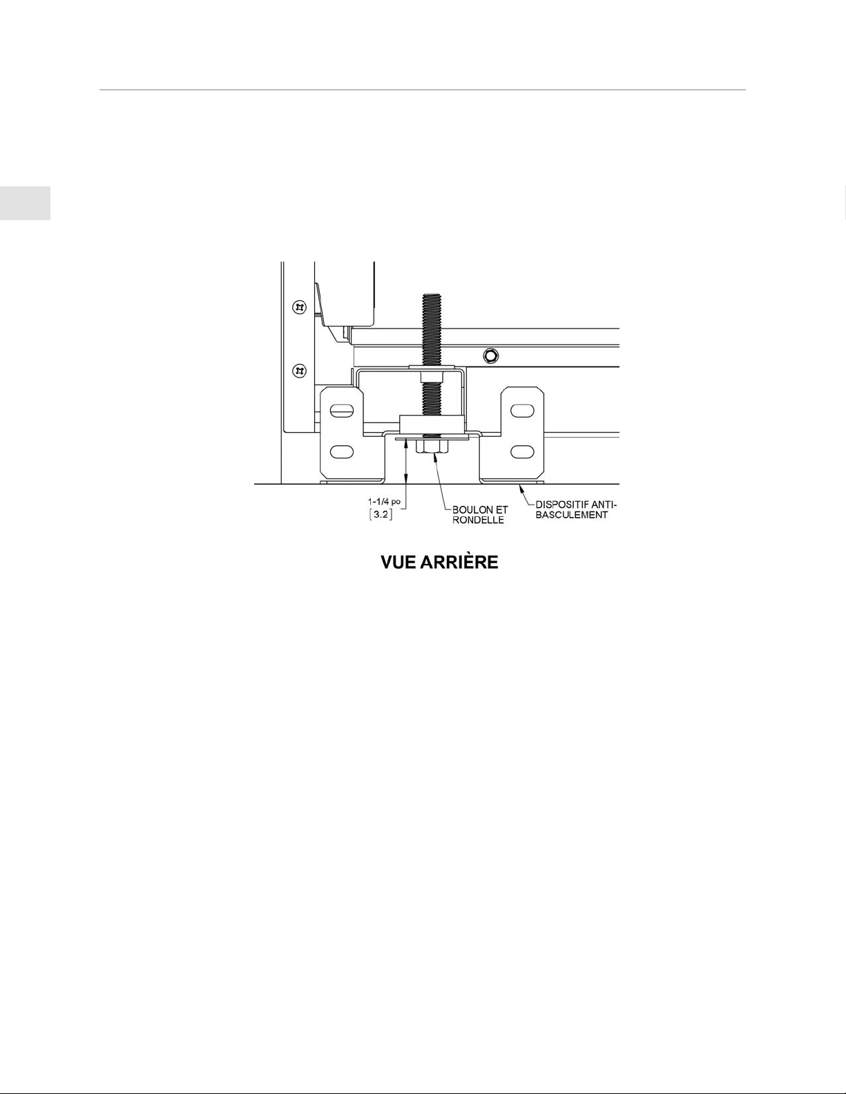
16
FR
©2020 Hestan Commercial Corporation
INSTALLATION DU DISPOSITIF ANTI-BASCULEMENT
(SUITE)
AJUSTEMENT DU BOULON ANTI-BASCULEMENTAJUSTEMENT DU BOULON ANTI-BASCULEMENT
Après avoir mis à niveau la cuisinière, et après avoir fixé le support, réglez le boulon anti-basculement et
la grosse rondelle sous la cuisinière de façon à ce que le dessus de la rondelle soit à 1-1/4 po [3,2 cm] au
maximum du plancher. Faites glisser la cuisinière dans l’ouverture du support et vérifiez que le boulon est
engagé dans le support comme indiqué ci-dessous. Faites délicatement basculer la cuisinière vers l’avant
pour vérifier. La cuisinière ne doit pas bouger de plus de 1 po [2,5 cm].
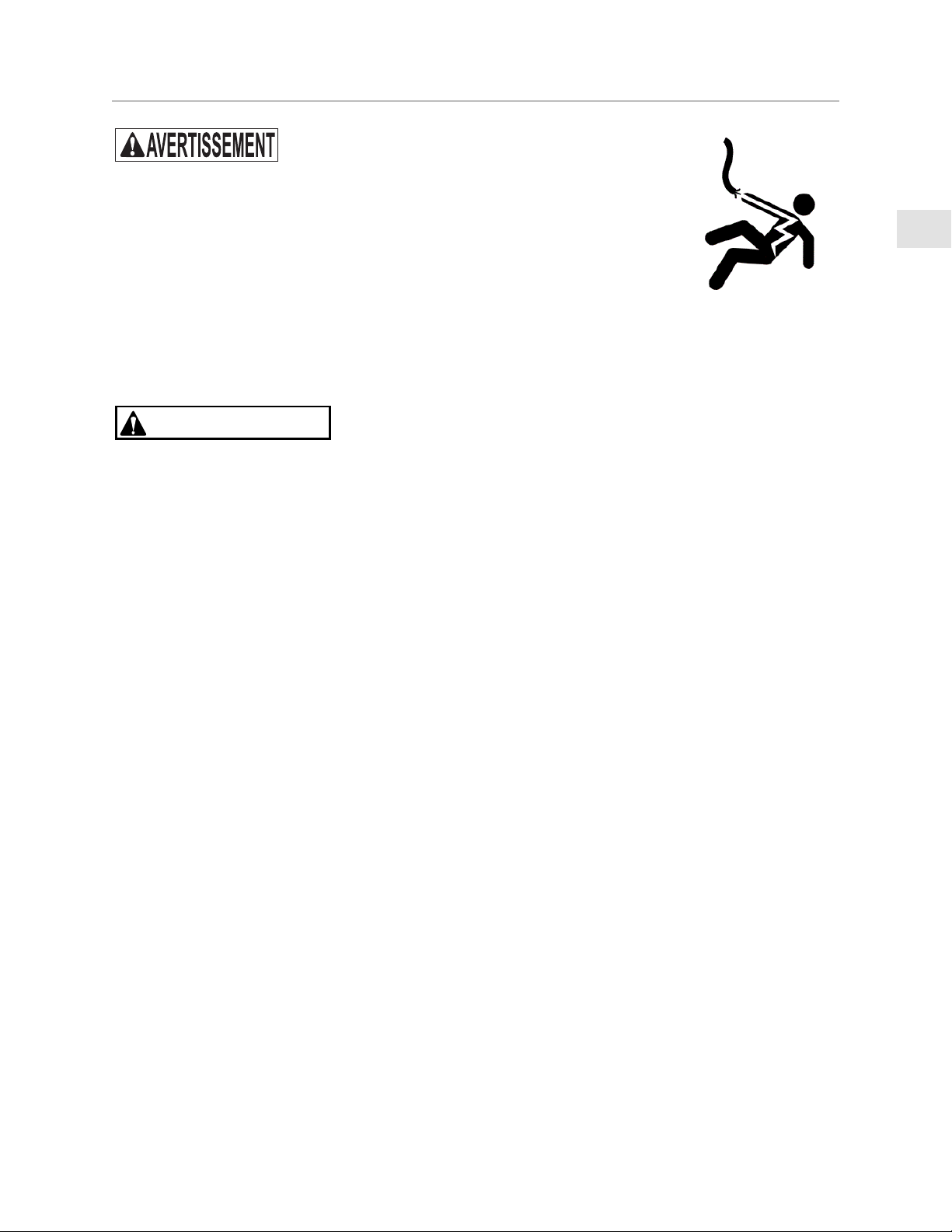
17
FR
©2020 Hestan Commercial Corporation
RISQUE DE CHOC ÉLECTRIQUERISQUE DE CHOC ÉLECTRIQUE
Débranchez l’alimentation avant d’installer ou d’entretenir l’appareil. Avant de
mettre l’appareil sous tension, assurez-vous que toutes les commandes sont en
position «OFF». Ne pas le faire peut entraîner un choc électrique ou la mort.
MISE À LA TERRE ÉLECTRIQUEMISE À LA TERRE ÉLECTRIQUE
Cet appareil doit être mis à la terre. La mise à la terre réduit le risque de choc électrique en cas de court-
circuit. La mise à la terre par le conducteur neutre est interdite pour les nouvelles installations de circuit
de dérivation (1996 NEC), ainsi dans les maisons mobiles et les véhicules récréatifs, ou dans une zone où
les codes locaux l’interdisent. Votre cuisinière Hestan est équipée d’une prise à trois broches de mise à la
terre qui doit être branchée dans une prise 120V à 3 broches mise à la terre.
PRÉCAUTION
Une mise à la terre incorrecte entraînera des dysfonctionnements dans l’unité, tels que des étincelles
continues des allumeurs. Cela peut endommager l’appareil et créer une situation d’électrocution.
BRANCHEMENT ÉLECTRIQUEBRANCHEMENT ÉLECTRIQUE
La prise doit avoir son propre circuit distinct - 120 VAC, monophasé, 60 Hz, avec un ampérage nominale de
15 ampères. Si aucune n’est disponible, un électricien agréé doit installer la prise distinct et mise à la terre
comme il convient. L’installation doit être effectuée conformément aux codes locaux, ou en l’absence de
codes locaux, elle doit être installée conformément au Code National de l’Électricité, ANSI / NFPA 70.
1. Assurez-vous que le panneau d’alimentation / disjoncteur est hors tension.
2. Raccordez l’appareil dans la prise murale. Sécurisez le cordon pour qu’il ne puisse pas se coincer ou se
coincer derrière la cuisinière.
3. Avant de rétablir l’alimentation sur le panneau d’alimentation / disjoncteur, assurez-vous que toutes
les commandes sont en position «OFF».
BRANCHEMENTS ÉLECTRIQUES
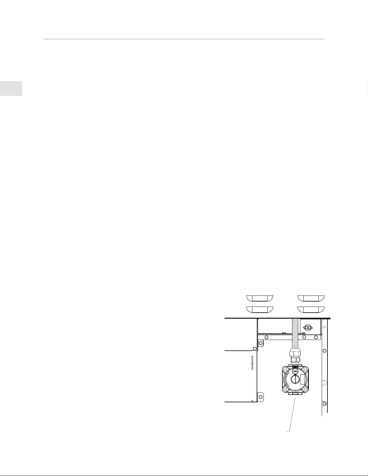
18
FR
©2020 Hestan Commercial Corporation
ALIMENTATION EN GAZALIMENTATION EN GAZ
Consulter les autorités locales responsables ou le fournisseur lors de la phase de planification de
l’installation afin de vérifier qu’un approvisionnement suffisant en gaz (gaz naturel ou GPL) est disponible.
S’il s’agit d’une nouvelle installation, demander aux autorités locales responsables ou au fournisseur de
vérifier la capacité du compteur et la tuyauterie pour s’assurer que l’appareil reçoit le volume et la pression
de gaz dont il a besoin pour fonctionner.
Faire effectuer les raccordements de gaz par un plombier qualifié ou un installateur professionnel
d’appareils de cuisson.
Tous les appareils doivent être équipés d’un robinet d’arrêt amont de gaz accessible permettant de les
isoler pour arrêt d’urgence et entretien.
S’assurer que la tuyauterie et les raccordements nouveaux ont été posés dans des conditions de propreté
et purgés de façon à empêcher de la pâte à tuyau, des débris, etc. de boucher les détendeurs, robinets,
orifices calibrés ou brûleurs. Utiliser une pâte à tuyau ou pâte d’étanchéité pour raccords filetés
homologuées pour le gaz naturel et le GPL.
L’appareil doit être isolé du système de tuyauterie d’alimentation en gaz en fermant son robinet d’arrêt
manuel individuel pendant tout test de pression de ce système à des pressions d’essai égales ou inférieures
à 1/2 livres/po² [3,5 kPa].
NE JAMAIS RACCORDER L’ APPAREIL UNE ALIMENTATION EN GAZ SANS DÉTENDEUR. Avant de
procéder à l’installation, s’assurer que l’appareil est adapté au gaz naturel ou au GPL. Le raccordement
à une alimentation en gaz incorrect entraînera un rendement médiocre et un risque accru de dégâts
matériels ou de blessures. Le type et la consommation (BTU/h) de gaz de chaque type de brûleur sont
indiqués sur la plaque signalétique.
L’installation de cet appareil de cuisson doit être effectuée conformément aux codes locaux. En l’absence
de tels codes, installer cet appareil conformément au National Fuel Gas Code ANSI Z223.1/NFPA 54, au
code Natural Gas and Propane Installation CSA B149 ou au Propane Storage and Handling Code B149.2.
REMARQUE : REMARQUE : Voir la plaque signalétique pour la pression d’admission du type de gaz de l’appareil.
La connexion de gaz à l’arrière de la cuisinière (voir ci-dessous) comporte des filetages de 1/2“NPT interne.
Utilisez un tuyau flexible en acier inoxydable (semi-rigide) d’un diamètre interne d’au moins 3/4 po (1 po
de diamètre extérieur) avec les raccords appropriés pour éviter les pénuries de gaz. Ce flexible ne devrait
pas avoir plus de 48 po [1,2 m] de longueur. Appliquer de la pâte d’étanchéité appropriée sur tous les
raccords. Ne pas appliquer de pâte d’étanchéité sur les raccords évasés.
La flexible d’alimentation ne doit pas interférer avec l’arrière de
la cuisinière. Soyez prudent lorsque vous poussez la cuisinière
contre le mur arrière, afin de ne pas plier ou pincer le flexible car
cela pourrait entraîner une fuite de gaz.
KITS DE CONVERSIONKITS DE CONVERSION
Dans le cas où votre appareil Hestan doit être converti du Gaz
Naturel au GPL, ou vice-versa, vous devrez contacter le service
clientèle de Hestan pour faire effectuer cette conversion. Celle-
ci doit être effectuée que par un technicien qualifié.
KITS DE HAUTE ALTITUDEKITS DE HAUTE ALTITUDE
Si vous vivez dans une région à haute altitude, c’est-à-dire au
moins 2000 pi [610 m] au-dessus du niveau de la mer, votre
appareil peut exiger des orifices calibrés différents pour une
combustion et un rendement appropriés. Vous devrez contacter
le service clientèle de Hestan pour faire effectuer cette opération.
Les kits Haute Altitude doivent être installés par un technicien
qualifié. Veuillez avoir les informations relatives aux numéros de
modèle et de série à portée de la main lorsque vous appelez.
RACCORDEMENT DE GAZ
1/2”NPT
INTERNE

19
FR
©2020 Hestan Commercial Corporation
RACCORDEMENT DE GAZ
(SUITE)
RACCORDEMENT DE GAZ - GAZ NATURELRACCORDEMENT DE GAZ - GAZ NATUREL
Pour faire en sorte que cet appareil chauffe bien, vérifier que la pression dans la conduite d’alimentation en
gaz est suffisante. L’appareil est fourni avec un détendeur de pression de gaz déjà installé. Ce détendeur
est réglé pour une pression d’alimentation de 7-14 po à la colonne d’eau [1,74-3,48 kPa] pour maintenir une
pression de sortie (collecteur) nominale de 5 po à la colonne d’eau [1,24 kPa].
S’assurer que la conduite de branchement alimentant l’appareil est pourvue d’un robinet d’arrêt facile
d’accès permettant de couper le gaz en cas d’urgence.
RACCORDEMENT DE GAZ – PROPANE LIQUIDE (GPL)RACCORDEMENT DE GAZ – PROPANE LIQUIDE (GPL)
Si vous avez acheté une version GPL de votre appareil, il sera fourni avec un détendeur de pression de gaz
déjà installé.
Ce détendeur est réglé pour maintenir une pression de sortie (collecteur) nominale de 10 po à la colonne
d’eau [2,49 kPa]. Assurez-vous que la flexible d’alimentation de l’appareil est équipé d’un robinet d’arrêt
facile d’accès permettant de couper le gaz en cas d’urgence.
Lors de la connexion au GPL, vérifiez que le réservoir est équipé de son propre détendeur haute pression.
La pression du gaz fourni à l’appareil doit être 11-14 po à la colonne d’eau [2,74-3.48 kPa].
CONTRÔLE D’ÉTANCHÉITÉCONTRÔLE D’ÉTANCHÉITÉ
GÉNÉRALITÉSGÉNÉRALITÉS
Bien que l’étanchéité de tous les raccordements de gaz de ce appareil Hestan ait été contrôlée à l’usine
préalablement à l’expédition, un contrôle complet d’étanchéité doit être effectué sur le lieu d’installation
pour tenir compte d’un possible déplacement en cours de transport ou d’une pression excessive exercée par
mégarde sur certaines pièces de l’appareil. Contrôler régulièrement l’étanchéité de l’ensemble du système
ou le faire immédiatement si on perçoit une odeur de gaz. L’essai d’étanchéité de l’appareil doit être executé
conformément aux instructions suivantes:
AVANT LE CONTRÔLEAVANT LE CONTRÔLE
NE PAS FUMER PENDANT LE CONTRÔLE D’ÉTANCHÉITÉNE PAS FUMER PENDANT LE CONTRÔLE D’ÉTANCHÉITÉ
• Ne jamais contrôler l’étanchéité avec une flamme nue.
• Préparer une solution savonneuse consistant en un volume de détergent liquide et un volume d’eau à
des fins de contrôle d’étanchéité.
• Appliquer de la solution sur les raccords de gaz à l’aide d’un flacon pulvérisateur ou d’un pinceau.
POUR EFFECTUER LE CONTRÔLEPOUR EFFECTUER LE CONTRÔLE
• S’assurer que toutes les robinets de réglage sont en position «OFF».
• Appliquer de la solution savonneuse décrite plus haut sur tous les raccords et le flexible.
• Ouvrir l’arrivée de gaz.
• Contrôler tous les raccordements depuis la conduite d’alimentation jusqu’à la connexion du détendeur
à l’arrière de l’appareil.
• Des bulles de savon se formeront à l’emplacement d’une fuite. En cas de fuite, couper immédiatement
l’arrivée de gaz, resserrer tout raccord qui fuit, rouvrir l’arrivée de gaz et recommencer le contrôle.
• S’il s’avère impossible d’arrêter une fuite de gaz, couper l’arrivée de gaz et s’adresser au
concessionnaire qui a vendu l’appareil.
• Ne pas utiliser l’appareil tant que tous les raccordements n’ont pas été contrôlés et qu’ils fuient.
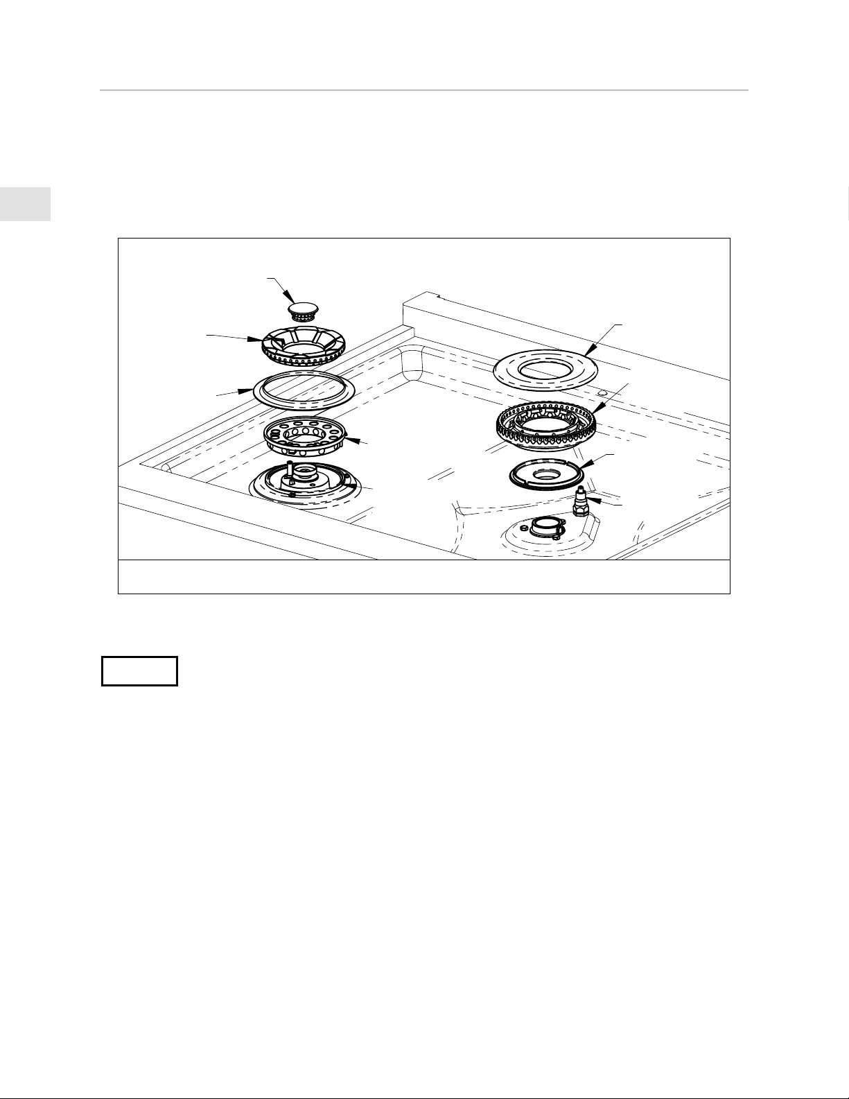
20
FR
©2020 Hestan Commercial Corporation
PHASE FINALE DE L’INSTALLATION
Enlevez les matériaux d’emballage final et les films protecteurs de toutes les zones extérieures. Vérifiez
à l’intérieur du four pour voir s’il y a d’autres articles d’emballage, du ruban adhésif sur les grilles du four,
etc. Installez tous les éléments non fixés tels que les chapeaux de brûleurs scellées, les grilles de cuisson,
etc. Assurez-vous que les chapeaux des brûleurs scellées sont bien en place sur la base du brûleur comme
indiqué ci-dessous. Il y a des encoches sur la base du brûleur et une anneau transversale pour faciliter
l’alignement. Le dessus du chapeau du brûleur externe comporte une longue fente qui s’aligne sur
l’allumeur par étincelle. L’assemblage du chapeau du brûleur à flux simple est similaire.
Avant de tester le fonctionnement de l’appareil, vérifiez que le contrôle de fuite a été effectué et que
l’appareil a été remis sous tension. Tournez le robinet d’arrêt de gaz en position ouverte.
AVIS
Tous les boutons de commande doivent être en position OFF pour empêcher tout fonctionnement
accidentel à la mise sous tension.
En cas de panne de courant, le four s’éteindra. Les brûleurs de surface continueront à brûler, mais doivent
être allumés manuellement avec un briquet ou une allumette appropriés. Une fois le courant rétabli,
le four ne fonctionnera pas tant que les boutons du four ne sont pas à la position OFF. Réglez tous les
boutons sur OFF et reprenez l’utilisation normale.
N’ESSAYEZ PAS D’UTILISER LA CUISINIÈRE PENDANT UNE PANNE DE COURANT PROLONGÉE.
Vérifiez l’allumage à chaque brûleur. L’allumeur émettra un déclic jusqu’à ce que la flamme s’allume dans
les 4 secondes, puis le déclic s’arrêtera. Vérifiez les caractéristiques de la flamme de chaque brûleur selon
les descriptions ci-dessous. Les flammes doivent être stables et ne pas danser ni s’arracher des orifices
du brûleur. La flamme peut devoir brûler pendant quelques minutes pour purger les conduits de gaz des
impuretés. Celles-ci apparaissent comme des pointes oranges intermittentes ou même de minuscules
étincelles dans la flamme. Ceci est normal et la flamme finira par se stabiliser comme celles montrées sur
l’illustration ci-dessous.
Si, après quelques minutes, les flammes continuent de brûler surtout en jaune, vérifiez que le chapeau
de brûleur est bien en place sur la base, puis refaites le test. Soyez prudent lorsque vous manipulez les
chapeaux du brûleurs. Ils peuvent être très chauds.
ANNEAU DE
BRÛLEUR
CHAPEAU
DE BRÛLEUR
BASE DE
BRÛLEUR
ALLUMEUR
CHAPEAU
BRÛLEUR
INTERNE
CHAPEAU
BRÛLEUR
EXTERNE
ANNEAU
TRANSVERSALE
BASE DE
BRÛLEUR
ANNEAU
DÉCORATIF
BRÛLEUR
DOUBLE FLUX
BRÛLEUR À
FLUX SIMPLE
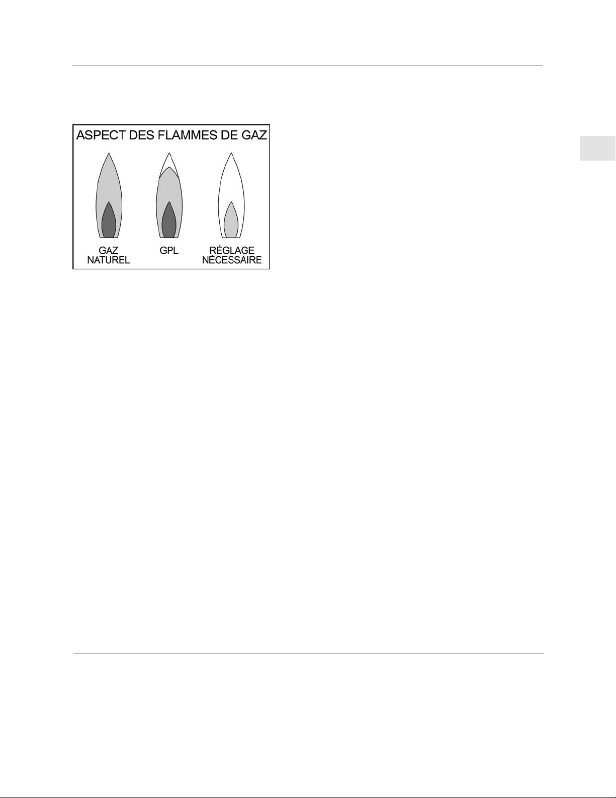
21
FR
©2020 Hestan Commercial Corporation
PHASE FINALE DE L’INSTALLATION
(SUITE)
Tournez le bouton de commande à la position de mijotage pour vérifier la fonction.
Vérifiez chaque brûleur individuellement, puis vérifiez qu’ils fonctionnent de manière satisfaisante avec les
autres brûleurs allumés.
Flamme bleu clair - Flamme normale de gaz naturel
Flamme bleu clair avec des pointes jaunes - Flamme normale
de gaz GPL
Flamme jaune - Réglage nécessaire
PLAQUE CHAUFFANTEPLAQUE CHAUFFANTE
La plaque chauffante n’a pas de réglages flamme/brûleur. Tournez le bouton de commande sur HIGH,
vérifiez que la plaque chauffante chauffe. Vous pouvez également remarquer une lueur orange constante
aux l ‘events a l’arrière de la plaque chauffante. Ceci est normal pendant le fonctionnement de la plaque
chauffante.
Éteignez tous les brûleurs lorsque le test est terminé.
Si tous les tests qui précèdent continuent de produire des flammes surtout jaunes ou que les brûleurs ne
s’allument pas, contactez le service clientèle de Hestan pour faire effectuer la réparation.
FONCTIONNEMENT DU FOURFONCTIONNEMENT DU FOUR
Toutes les vérifications de la table de cuisson doivent être effectuées avant la vérification du
fonctionnement du four.
Ouvrez et fermez la porte du four pour vérifier que les lumières du four s’allument à l’ouverture et
disparaissent une fois fermées. Eteignez les lumières du four à l’aide de l’interrupteur du panneau de
commande pour valider le bon fonctionnement.
Avec la porte ouverte, réglez le sélecteur de mode sur BAKE et le sélecteur de température sur 350° F. Les
deux boutons du rétroéclairage s’allumeront et le indicateur orange «chauffage» s’allumera. L’allumeur de
cuisson (situé sous le bac de graisse inférieur) commence à briller et une fois qu’il a atteint la température
appropriée, la robinet de gaz est alimentée. Vérifiez les caractéristiques d’allumage et de flamme du brûleur.
Fermez la porte du four. Réglez le bouton de mode et le bouton de température sur BROIL. Les deux
boutons du rétroéclairage s’allumeront et le indicateur orange «chauffage» s’allumera. L’allumeur de
grillage (situé en haut de la cavité du four) commence à briller et une fois que la température appropriée est
atteinte, la robinet à gaz est alimentée. Vérifiez les caractéristiques d’allumage et de flamme du brûleur de
grillage.
Éteignez le four.
REMARQUE: Une petite quantité de fumée et d’odeur peut être notée pendant cet essai et pendant la
période de rodage initiale.
SERVICE
Toutes les réparations sous garantie et hors garantie doivent être effectuées par un technicien qualifié.
Pour trouver un réparateur agrée dans votre région, contactez votre concessionnaire Hestan, votre
représentant local, ou Hestan. Avant d’appeler, veuillez avoir sous la main le numéro de modèle et le
numéro de série.
Hestan Commercial Corporation
3375 E. La Palma Avenue
Anaheim, CA 92806
(888) 905-7463

22
FR
©2020 Hestan Commercial Corporation
APPENDICE
TABLEAU 1 - OPTIONS DU DOSSERETTABLEAU 1 - OPTIONS DU DOSSERET
MODÈLE DE MODÈLE DE
CUISINIÈRECUISINIÈRE
MODÈLE DE DOSSERETMODÈLE DE DOSSERET DESCRIPTIONDESCRIPTION
KRG304 KBGIT30* DOSSERET, PROFILE POUR ÎLOT, 30 PO
KBGLB30 DOSSERET, ARRIÈRE BAS, 30 PO
KBGHS30 DOSSERET, ÉTAGÈRE HAUTE , 30 PO
KRG365 KBGIT36* DOSSERET, PROFILE POUR ÎLOT, 36 PO
KBGLB36 DOSSERET, ARRIÈRE BAS, 36 PO
KBGHS36 DOSSERET, ÉTAGÈRE HAUTE , 36 PO
KRG364GD KBGIT36* DOSSERET, PROFILE POUR ÎLOT, 36 PO
KBGLB36 DOSSERET, ARRIÈRE BAS, 36 PO
KBGHS36 DOSSERET, ÉTAGÈRE HAUTE , 36 PO
KRG485GD KBGIT48* DOSSERET, PROFILE POUR ÎLOT, 48 PO
KBGLB48 DOSSERET, ARRIÈRE BAS, 48 PO
KBGHS48 DOSSERET, ÉTAGÈRE HAUTE , 48 PO
KRG484GD KBGIT48* DOSSERET, PROFILE POUR ÎLOT, 48 PO
KBGLB48 DOSSERET, ARRIÈRE BAS, 48 PO
KBGHS48 DOSSERET, ÉTAGÈRE HAUTE , 48 PO
* INCLUS AVEC CUISINIÈRE

23
FR
©2020 Hestan Commercial Corporation
CETTE PAGE N’EST PAS UTILISÉE.

Hestan Commercial Corporation
3375 E. La Palma Ave.
Anaheim, CA 92806
(888) 905-7463
RETAIN THIS MANUAL FOR FUTURE REFERENCE
CONSERVEZ CE MANUEL POUR UNE RÉFÉRENCE FUTURE
©2020 Hestan Commercial Corporation P/N 027941 REV E