Loading ...
Loading ...
Loading ...

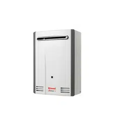
Rinnai 15 HW_CF OIM
NOTE
INSTALLATION, SERVICE AND REMOVAL MUST BE BY AN AUTHORISED PERSON ONLY�
It is the installer’s responsibility to ensure all current AS/NZS 5601 requirements are met�
Remove transit protection� Check for damage, if any is found DO NOT install and contact supplier�
REGULATIONS
This appliance must be installed in accordance with:
•
Current AS/NZS 3000, AS/NZS 3500 and AS/NZS 5601
•
Rinnai Installation Instructions
•
Local regulations and municipal building codes including local OH&S requirements
APPLICABLE MODELS
These Installation Instructions apply only to the Rinnai Continuous Flow Water Heater models that are listed on
the cover page of this manual�
APPLIANCE LOCATION
This appliance is designed for ‘Outdoor’ Installation only� As such, it MUST BE located in an above ground open
air situation with natural ventilation, without stagnant areas, where gas leakage and products of combustion are
rapidly dispersed by wind and natural convection�
This appliance MUST BE mounted on a vertical structure with the water and gas connections on the underside
pointing downwards. For appliances installed on elevated structures or under oors specic requirements apply.
Refer to AS/NZS 5601 Section 6 for details�
Location of the appliance ue terminal MUST BE in accordance with Section 6 and Figure 6�2 of AS/NZS 5601� An
extract (in part) has been reproduced in the "Appliance Flue Terminal" section of these instructions on page 18.
This appliance MUST BE placed as close as practicable to the most frequently used hot water outlet or outlets to
minimise the delay time for hot water delivery� For installations where the distance between the water heater and
the outlets is considerable, a ow and return system or the Rinnai Smartstart® system can be used which minimise
the waiting time for hot water delivery�
Alternatively, multiple appliances can be strategically placed to serve outlets with minimal delay time� Contact
Rinnai for further information�
An AC 230V/10 Amp, earthed power point MUST BE provided adjacent to the appliance� For outdoor installations
this power point MUST BE weather proof� It MUST BE clear of the gas and water connections to the appliance and
also the ue exhaust and water pressure relief valve. The power cord of the appliance is 1.5 Metres long.
All appliances MUST BE installed to ensure access can be gained without hazard or undue difculty for inspection,
repair, renewal or operational purposes. Sufcient clearances shall allow access to, and removal of, all serviceable
components. Appliances should not be mounted higher than 2.5 metres above the ground or oor level unless
the customer can arrange permanent and safe access or can provide another means of access, for example, by
means of scissor or boom lifts acceptable to local authorities�
This appliance MUST NOT be used as a domestic spa or swimming pool heater�
Mounting Of Appliance
The wall or structure on which the units are to be mounted MUST BE capable of supporting these weights and
the associated pipe-work� Refer to "Table 2� Supply, Flow rates, Weights & Flow & Service Connections" on page
27 for specic model weights.
Ensure that suitable xing screws or bolts are used to secure the units to the wall, in accordance with AS/NZS 5601
section 6� Wooden plugs shall not be used�
The top bracket has a keyhole slot so that the appliance can be positioned by hanging it on one screw, once in
position the appliance can then be fully secured with the application of further appropriate ttings.
The appliance can be mounted directly against the wall or structure� There is no need to use, non combustible
sheeting or leave an air gap between the appliance back panel and the wall or structure to meet the temperature
hazard requirements of AS/NZS 5601.
GENERAL INSTALLATION INFORMATION
Loading ...
Loading ...
Loading ...
