Loading ...
Loading ...
Loading ...
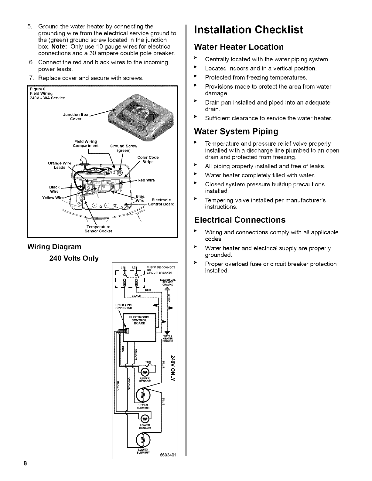
5. Groundthewaterheaterbyconnectingthe
groundingwirefromtheelectricalservicegroundto
the(green)groundscrewlocatedinthejunction
box.Note: Onlyuse10gaugewiresforelectrical
connectionsanda30amperedoublepolebreaker.
6. Connecttheredandblackwirestotheincoming
powerleads.
7. Replacecoverandsecurewithscrews.
Figure 6
Field Wiring
240V - 30A Service
Junction Box
Cover
Orange Wire
Leads
Black
Wire
Field Wiring
Compartment
L_
Ground Screw
(green)
Color Code
Stripe
Red Wire
Blu
r_ Electronic
Control Board
Temperature
Sensor Socket
Wiring Diagram
240 Volts Only
LI L2 FUSED DISCONNECT
CIRCUIT BREAKER
I o o I EL,O,R,C,,L
S_RVlCE
/ 8L,cK I_
CONNECTOR
ELECTRONIC
CONTROL
BOARD
III I-....
H_TER
GROU_ID
TOO
L_. =__
UPPER
SENSOR
LOWER
ELEMENT
6603491
Installation Checklist
Water Heater Location
_" Centrally located with the water piping system.
_" Located indoors and in a vertical position.
_" Protected from freezing temperatures.
_" Provisions made to protect the area from water
damage.
_" Drain pan installed and piped into an adequate
drain.
_" Sufficient clearance to service the water heater.
Water System Piping
_" Temperature and pressure relief valve properly
installed with a discharge line plumbed to an open
drain and protected from freezing.
_" All piping properly installed and free of leaks.
_" Water heater completely filled with water.
_" Closed system pressure buildup precautions
installed.
_" Tempering valve installed per manufacturer's
instructions.
Electrical Connections
Wiring and connections comply with all applicable
codes.
Water heater and electrical supply are properly
grounded.
Proper overload fuse or circuit breaker protection
installed.
Loading ...
Loading ...
Loading ...