Loading ...
Loading ...
Loading ...
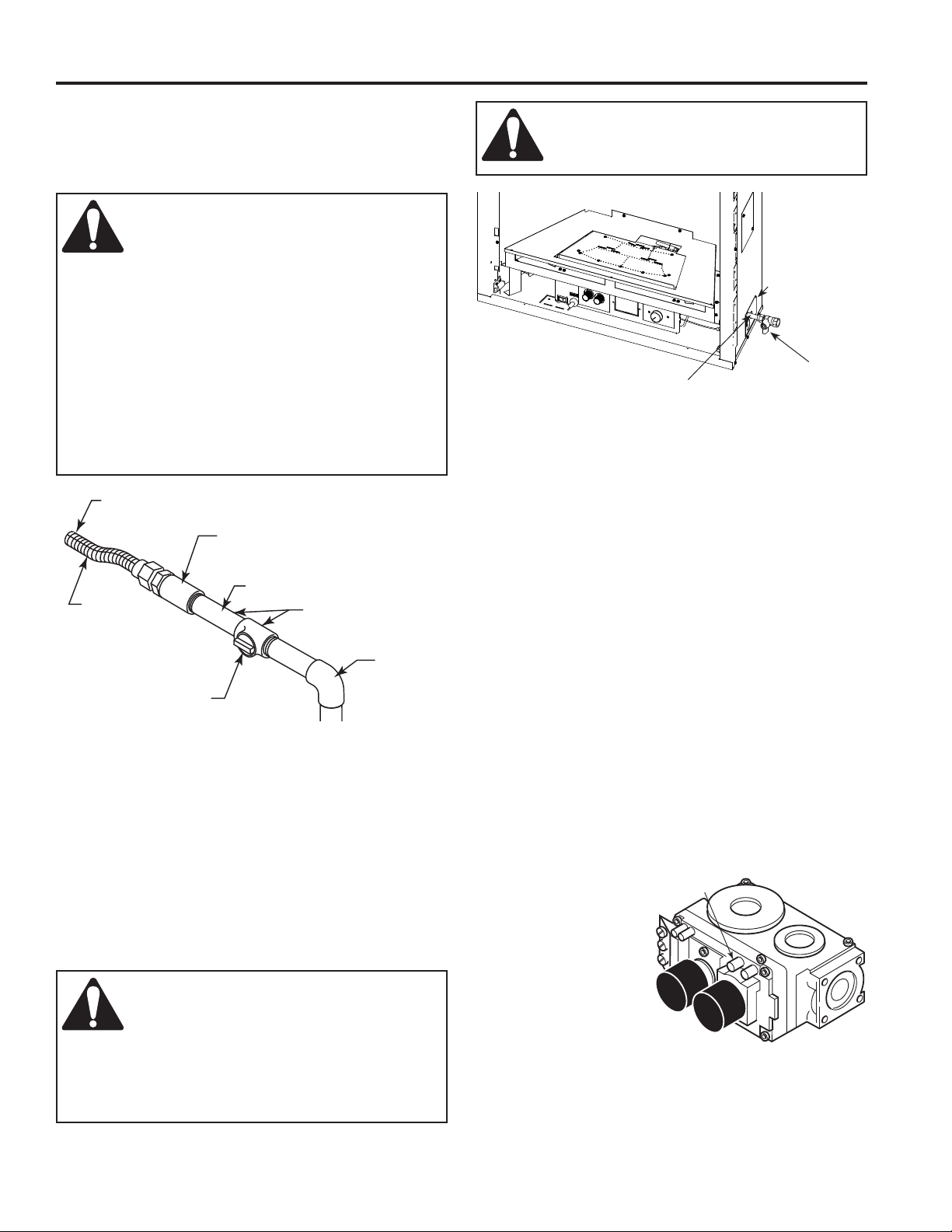
Test Port
"OUT"
12
20308011
VFC Vent Free Fireplace System
CONNECTING THE GAS LINE
NOTICE: A qualifi ed gas appliance installer must connect
the heater to the gas supply. Consult all local codes.
GAS LINE & PRESSURE
To Fireplace
Pipe Coupling
Stainless
Flexible Tube
Pipe
Locations Pressure
Tapping Point Instal-
lation
Manual Shutoff
Valve
Gas Supply
Inlet
Figure 10 -
Gas Connection
IMPORTANT: Loosen the pipe adapter on the fl ex tube
before installing to the system piping.
Always use an external regulator for all propane/LPG heat-
ers only, to reduce the supply tank pressure to a maximum
of 13" w.c. This is in addition to the internal regulator in the
heater valve.
To reach factory installed fl ex line, go through access door
on right or left side of fi rebox.
Figure 11 -
Access Holes
Manual Gas Shutoff
(Recommended Outlet
Positioned Vertical)
Stainless Flex Line
Access Door
for Gas Line
WARNING: Connecting directly to an
unregulated propane/LPG tank can
cause an explosion
WARNING: Use new black iron or
steel pipe. Internally tinned copper or
copper tubing can be used per National
Fuel Code, section 2.6.3, providing gas meets
hydrogen sulfi de limits, and where permitted by
local codes. Gas piping system must be sized to
provide minimum inlet pressure (Listed on Data
Plate) at the maximum fl ow rate (BTU/hr). Undue
pressure loss will occur if the pipe is too small.
A manual shutoff valve must be installed
upstream of the appliance. Union tee and
plugged 1/8" NPT pressure tapping point should
be installed upstream of the appliance. Figure 10
WARNING: CHECK GAS TYPE: The
gas supply must be the same as stated
on the heater’s rating plate. If the gas
supply is different, DO NOT INSTALL THE
HEATER. Contact your dealer for the correct
model. Connecting to the wrong gas type may
result in property damage or personal injury.
The stainless fl ex line is on the right side facing the fi re-
place and can connect to either a 3/8 NPT female or 1/2
NPT male pipe. To connect from the opposite side, route
the pipe under the rear portion of the unit.
Test all gas joints from the gas meter to the heater valve for
leaks using a gas analyzer or soap and water solution after
completing connection. DO NOT USE AN OPEN FLAME.
Check the gas pressure with the appliance burning and
the control set to HIGH.
Open control access door on either side of unit to fi nd valve
and regulator referred to below. Figure 11
CHECKING GAS PRESSURE – MILLIVOLT
CONTROL
Figure 12
The valve regulator controls the burner pressure which
should be checked at the pressure test point.
Turn captured screw counter clockwise two or three turns
and then place tubing
to pressure gauge over
test point (Use test point
“OUT” closest to con-
trol knob). After taking
pressure reading, be
sure and turn captured
screw clockwise firmly
to re-seal. Do not over
torque. Check for gas
leaks.
Figure 12 -
Pressure Test Point Location Millivolt Control
Loading ...
Loading ...
Loading ...