AV 32/36S33/36/320/330/360 ENG 10/2/02 _19 PM Page i
COLORTELEVISION
USER'SGUIDE
For models:
AV-36360
AV-36330
AV-36320
AV-36S36
AV-36S33
AV-32360
AV-32330
AV-32320
AV-32S36
AV-32S33
Illustration of AV-32360 and RM-C254
I PLEASE NOTE I
This web based PDF File for this instruction book is not an exact replica
of the nstruct on book that Comes w th the TV.
I IMPORTANT NOTE TO THE CUSTOMER
In the spaces below, enter the model and serial number of your television (located at the I
rear of the television cabinet). Staple your sales receipt or invoice to the inside cover of this
guide: Keep this user's guide in a convenient place for future reference . Keep the carton and
original packaging for future use.
Serial Number
Model Number
LCT1135-001B-A
0602-TN-FAA-JIM
AV 32/36S33/36/320/330/360 ENG 10/2/_M Page 2
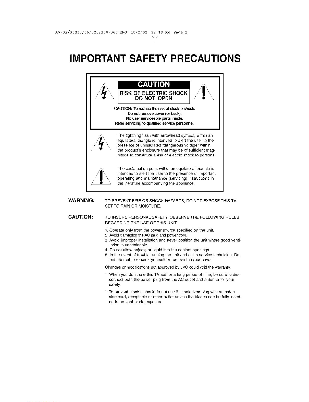
IMPORTANT SAFETY PRECAUTIONS
CAUTION: To reduce therisk of electric shock.
Do not remove cover (or back).
No user serviceable parts inside.
Refer servicing toqualified service personnel.
The lightning flash with arrowhead symbol, within an
equilateral triangle is intended to alert the user to the
presence of uninsulated "dangerous voltage" within
the product's enclosure that may be of sufficient mag-
nitude to constitute a risk of electric shock to persons.
The exclamation point within an equilateral triangle is
intended to atert the user to the presence of important
operating and maintenance (servicing) instructions in
the literature accompanying the appliance.
WARNING:
CAUTION:
TO PREVENT FIRE OR SHOCK HAZARDS, DO NOT EXPOSE THIS TV
SET TO RAIN OR MOISTURE.
TO INSURE PERSONAL SAFETY, OBSERVE THE FOLLOWING RULES
REGARDING THE USE OF THiS UNIT.
1. Operate only from the power source specified on the unit.
2. Avoid damaging the AC plug and power cord.
3. Avoid improper installation and never position the unit where good venti-
lation is unattainable.
4. Do not allow objects or liquid into the cabinet openings.
5. In the event of trouble, unplug the unit and call a service technician. Do
not attempt to repair it yourself or remove the rear cover.
Changes or modifications not approved by JVC could void the warranty.
* When you don't use this TV set for a long period of time, be sure to dis-
connect both the power plug from the AC outlet and antenna for your
safety.
* To prevent electric shock do not use this polarized plug with an exten-
sion cord, receptacle or other outlet unless the blades can be fully insert-
ed to prevent blade exposure.
AV 32/36S33/36/320/330/360 ENG 10/2/_M Page 3
IMPORTANT SAFEGUARDS
CAUTION:
Please read and retain for your safety.
Electrical energy can perform many useful functions. This TV set has been engineered and
manufactured to assure your personal safety. But improper use can result in potential electrical
shock or fire hazards. In order not to defeat the safeguards incorporated in this TV set, observe
the following basic rules for its installation, use and servicing.
And also follow all warnings and instructions marked on your TV set.
INSTALLATION
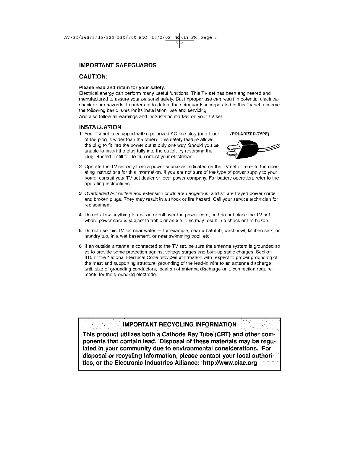
1 Your TV set is equipped with a polarized AC line plug (one blade
of the plug is wider than the other). This safety feature allows
the plug to fit into the power outlet only one way. Should you be
unable to insert the plug fully into the outlet, try reversing the
plug. Should it still fail to fit, contact your electrician.
(POLARIZED-TYPE)
2 Operate the TV set only from a power source as indicated on the TV set or refer to the oper-
ating instructions for this information. If you are not sure of the type of power supply to your
home, consult your TV set dealer or local power company. For battery operation, refer to the
operating instructions.
3 Overloaded AG outlets and extension cords are dangerous, and so are frayed power cords
and broken plugs. They may result in a shock or fire hazard. Call your service technician for
replacement.
4 Do not allow anything to rest on or roll over the power cord, and do not place the TV set
where power cord is subject to traffic or abuse. This may result in a shock or fire hazard.
5 Do not use this TV set near water -- for example, near a bathtub, washbowl, kitchen sink, or
laundry tub, in a wet basement, or near swimming poo!, etc.
6 If an outside antenna is connected to the TV set, be sure the antenna system is grounded so
as to provide some protection against voItage surges and built-up static charges. Section
810 of the National Electrical Code provides information with respect to proper grounding of
the mast and supporting structure, grounding of the lead-in wire to an antenna discharge
unit size of grounding conductors, location of antenna discharge unit, connection require-
ments for the grounding electrode.
This product utilizes both a Cathode Ray Tube (CRT) and other com.
portents that contain lead. Disposal of these materials may be regu,
lated in your community due to environmental considerations. For
disposal or recycling information, please contact your local authori-
ties, or the Electronic Industries Alliance: http:/hvww.eiae.org
AV 32/36S33/36/320/330/360 ENG 10/2/_M Page 4
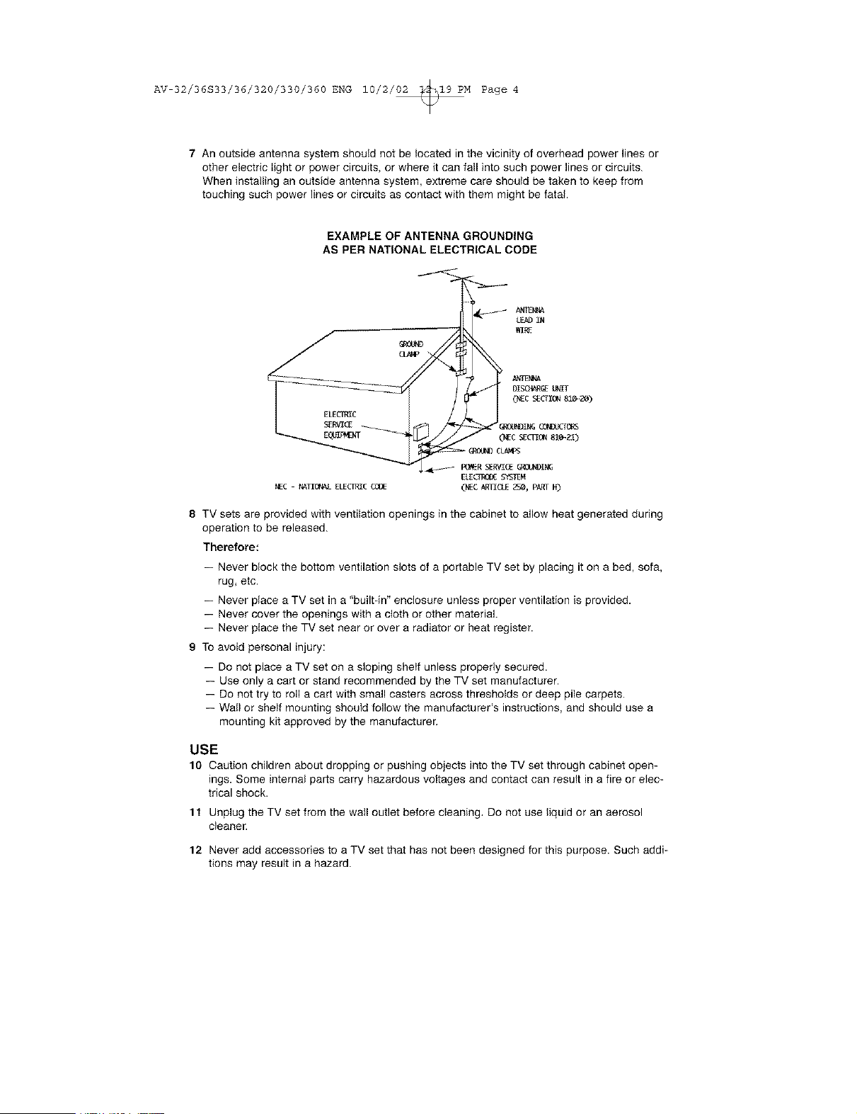
7 An outside antenna system should not be located in the vicinity of overhead power lines or
other electric light or power circuits, or where it can fail into such power lines or circuits.
When installing an outside antenna system, extreme care should be taken to keep from
touching such power lines or circuits as contact with them might be fatal.
EXAMPLE OF ANTENNA GROUNDING
AS PER NATIONAL ELECTRICAL CODE
TV sets are provided with ventilation openings in the cabinet to allow heat generated during
operation to be released.
Therefore:
-- Never block the bottom ventilation slots of a portable TV set by placing it on a bed, sofa,
rug, etc.
-- Never place a TV set in a "builtdn" enclosure unless proper ventilation is provided.
-- Never cover the openings with a cloth or other material.
-- Never place the TV set near or over a radiator or heat register.
9 To avoid personal injury:
-- Do not place a TV set on a sloping shelf unless properly secured.
-- Use only a cart or stand recommended by the TV set manufacturer.
-- Do not try to roll a cart with small casters across thresholds or deep pile carpets.
-- Wall or shelf mounting should follow the manufacturer's instructions, and should use a
mounting kit approved by the manufacturer,
USE
10 Caution children about dropping or pushing objects into the TV set through cabinet open-
ings. Some internal parts carry hazardous voltages and contact can result in a fire or elec-
trical shock.
1t Unplug the TV set fromthe wailoutlet before cleaning, Do not useliquid or anaerosol
cleaner.
12 Never add accessories to a TV set that has not been designed for this purpose. Such addi-
tions may result in a hazard.
AV 32/36S33/36/320/330/360 ENG 10/2/_M Page 5
13 For added protection of the TV set during a lightning storm or when the TV set is to be left
unattended for an extended period of time, unplug it from the wall outlet and disconnect the
antenna. This will prevent damage to product due to lightning storms or power line surges.
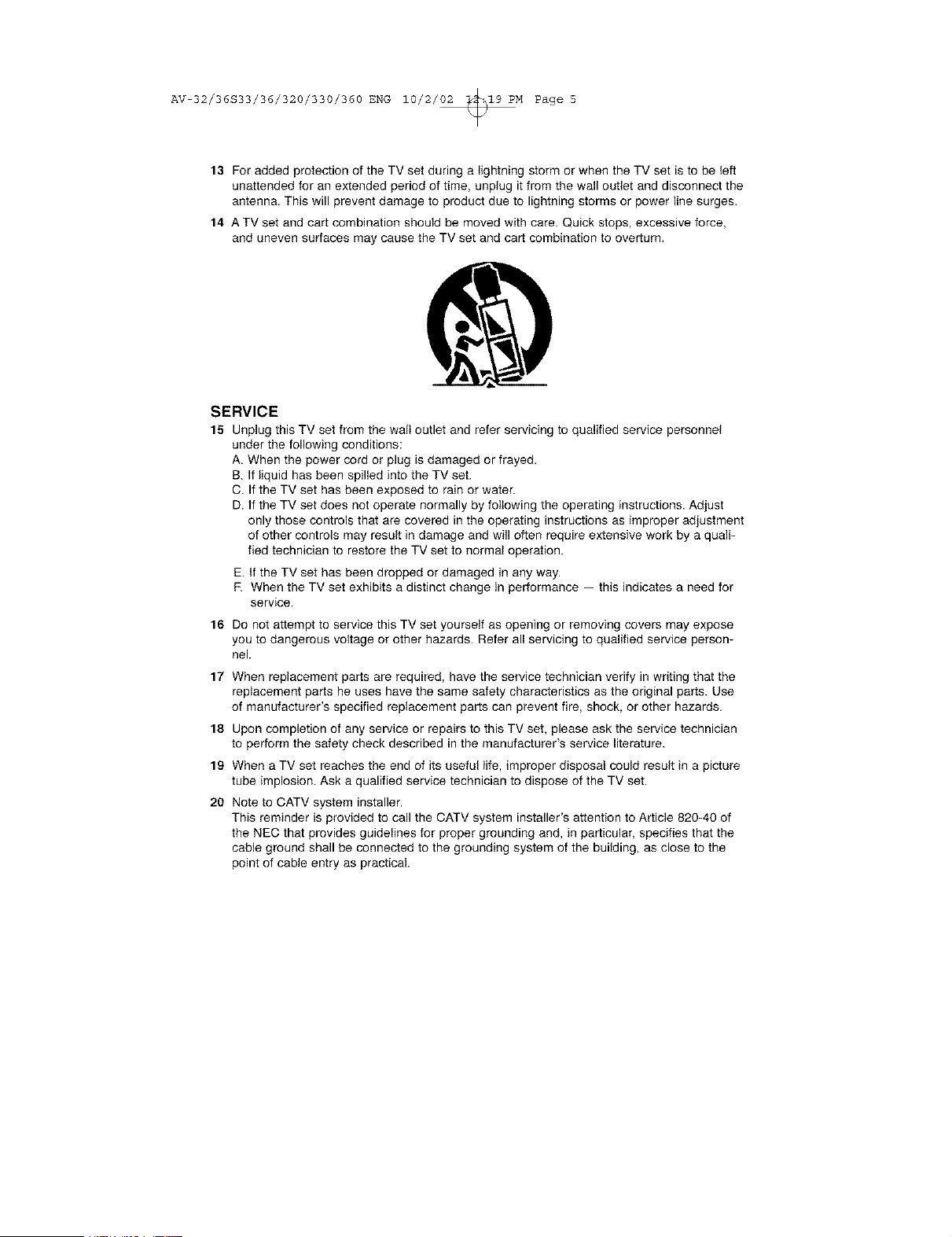
14 A TV set and cart combination should be moved with care. Quick stops, excessive force,
and uneven surfaces may cause the TV set and cart combination to overturn,
SERVICE
15 Unplug this TV set from the wali outlet and refer servicing to qualified service personnel
under the following conditions:
A. When the power cord or plug is damaged or frayed.
B. If liquid has been spilled into the TV set.
C. If the TV set has been exposed to rain or water.
D. If the TV set does not operate normally by following the operating instructions. Adjust
only those controls that are covered in the operating instructions as improper adjustment
of other controls may result in damage and will often require extensive work by a quali-
fied technician to restore the TV set to normal operation.
E. If the TV set has been dropped or damaged in any way.
R When the TV set exhibits a distinct change in performance -- this indicates a need for
service.
16 Do not attempt to service this TV set yourself as opening or removing covers may expose
you to dangerous voltage or other hazards. Refer all servicing to qualified service person-
nel.
17
18
19
20
When replacement parts are required, have the service technician verify in writing that the
replacement parts he uses have the same safety characteristics as the original parts. Use
of manufacturer's specified replacement parts can prevent fire, shock, or other hazards,
Upon completion of any service or repairs to this TV set, please ask the service technician
to perform the safety check described in the manufacturer's service literature.
When a TV set reaches the end of its useful life, improper disposal could result in a picture
tube implosion. Ask a qualified service technician to dispose of the TV set.
Note to CATV system installer.
This reminder is provided to call the CATV system installer's attention to Article 820-40 of
the NEC that provides guidelines for proper grounding and, in particular, specifies that the
cable ground shall be connected to the grounding system of the building, as close to the
point of cable entry as practical.
AV 32/36S33/36/320/330/360 ENG 10/2/_M Page 6
Table of Contents
UNPACKING YOUR TV ..... 7
TV Models and
Remote Controls ........ 8
Quick Setup Guide ....... 11
Connections .......... 14
Cable and VCR Connections ....... 14
Connecting to a DVD Player ....... 17
Connecting to an External Amplifier , . . 18
Connecting to a Camcorder ....... 18
Onscreen Menus (Cont.)
Sound Settings ............. 39
Bass ............. 39
Treble .............. 39
Balance ............. 39
MTS (Multi-channel Sound . . 39
General items .............. 40
On/Off Timer .......... 40
Closed Caption ........ 41
Front Panel Lock ....... 41
Auto Shut Off ........ 42
XDS ID ............ 42
V2 Component-In!
Vl Component-in ....... 42
Remote Control ......... 19
Remote Control Basics .... 19
Changing the Batteries ..... 19
Remote Programming ..... 20
CATV and Satellite Codes ........ 20
VCR Codes ............... 21
DVD Codes ............... 22
Onscreen Menus ........ 23
Using the Guide ............. 23
Onscreen Menu System ......... 24
Plug In Menu .............. 25
Introduction .......... 25
Language ........... 25
Auto Tuner Setup ....... 25
Auto Clock Set ......... 26
Manual Clock Set ....... 27
Channel Summary ............ 28
V-Chip .................. 29
US V-Chip Ratings ....... 30
Viewing Guidelines ...... 30
Setting US V-Chip Ratings . . . 31
Movie Ratings ......... 33
Set Movie Ratings ....... 33
Canadian V-Chip Ratings . . . 34
Set Canadian V-Chip Ratings . 34
Unrated Programs ....... 35
Set Lock Code ......... 36
Picture Settings ............. 37
Tint .............. 37
Color ............. 37
Picture ............. 37
Bright ............. 37
Detail ............. 37
Noise Muting .......... 38
BUTTON FUNCTIONS ..... 43
Menu .................. 43
Exit and PIP Off ............. 43
Display .................. 43
Video Status ............... 44
Sleep Timer ............... 44
Hyper Surround ............. 44
Muting .................. 44
100+ ................... 45
Return+ ................. 45
Input ................... 45
VCR Buttons ............... 46
DVD Buttons ............... 46
TV/CATV Switch ............. 46
VCR/DVD Switch ............ 46
PiP (Picture-lmPicture) ......... 47
Introduction .......... 47
On/Move ........... 47
Freeze ............. 48
Swap ............. 48
Channel +/- .......... 48
Source ............ 48
EZ-Surf ............ 48
APPENDICES
Troubleshooting ............. 49
Warranty ................. 50
Authorized Service Centers ....... 52
Search Codes .............. 53
Specifications .............. 54
Note ................... 55
AV 32/36S33/36/320/330/360 ENG 10/2/_M Page 7
Unpacki ng You r Television
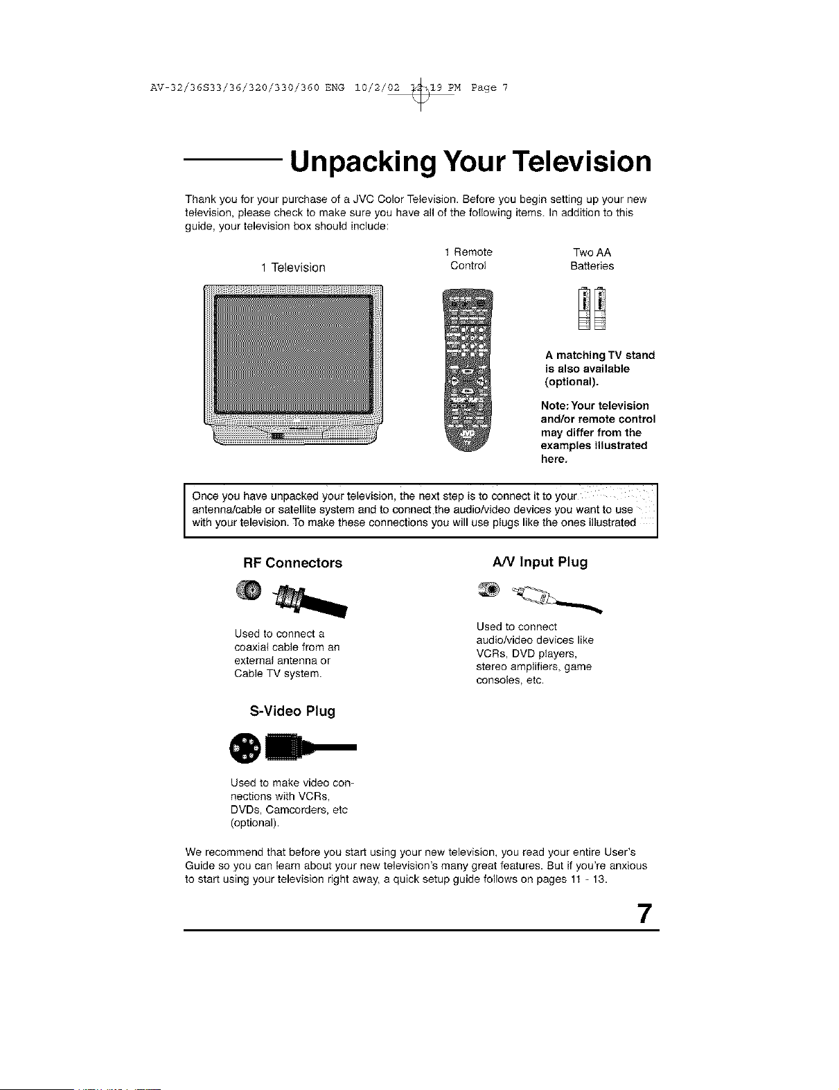
Thank you for your purchase of a JVC Color Television. Before you begin setting up your new
television, please check to make sure you have all of the following items. In addition to this
guide, your television box should include:
t Remote Two AA
1 Television Control Batteries
A matching TV stand
is also available
(optional).
Note: Your television
and/or remote control
may differ from the
examples illustrated
here.
I Once you have unpacked your television, the next step is to connect it to your I
I
antenna/cable or satellite system and to connect the audio/video devices you want to use
wthyourteevson, Tomaketheseconnectonsyouw usepugs ketheones ustrated
RF Connectors A/V Input Plug
Used to connect a
coaxial cable from an
external antenna or
Cable TV system.
S-Video Plug
Used to connect
audio/video devices like
VCRs, DVD players,
stereo amplifiers, game
consoles, etc.
Used to make video con-
nections with VCRs,
DVDs, Camcorders, etc
(optional).
We recommend that before you start using your new television, you read your entire User's
Guide so you can learn about your new television's many great features. But if you're anxious
to start using your television right away, a quick setup guide follows on pages 11 - 13.
7
AV 32/36S33/36/320/330/360 ENG 10/2/_M Page 8
TV Models and Remotes Guide --
NOTE: Before you connect your tetevison to another device, please refer to the proper dia-
grams for your TV and remote, depending on the model that you have purchased.
These will help assist you in understanding how to connect your television to another
device, as well as use the remote to set up your televison.
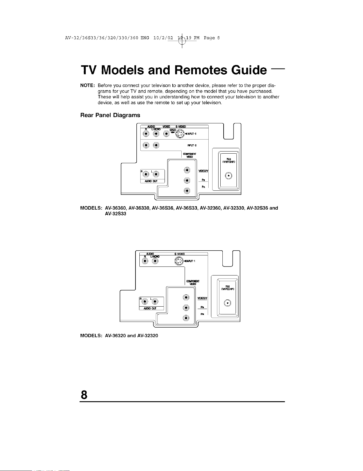
Rear Panel Diagrams
_L_ ®_@.,..,
INPI4T2
kF
MODELS: AV-36360, AV-36330, AV-36S36, AV-36S33, AV-32360, AV-32330, AV-32S36 and
AV-32S33
AUDIO
UI43NO
®
MODELS: AV-36320 and AV-32320
O ,91WRJTI
--
7Sg
_HF_UH
8
AV 32/36S33/36/320/330/360 ENG 10/2/_M Page 9
-- TV Models and Remotes Guide
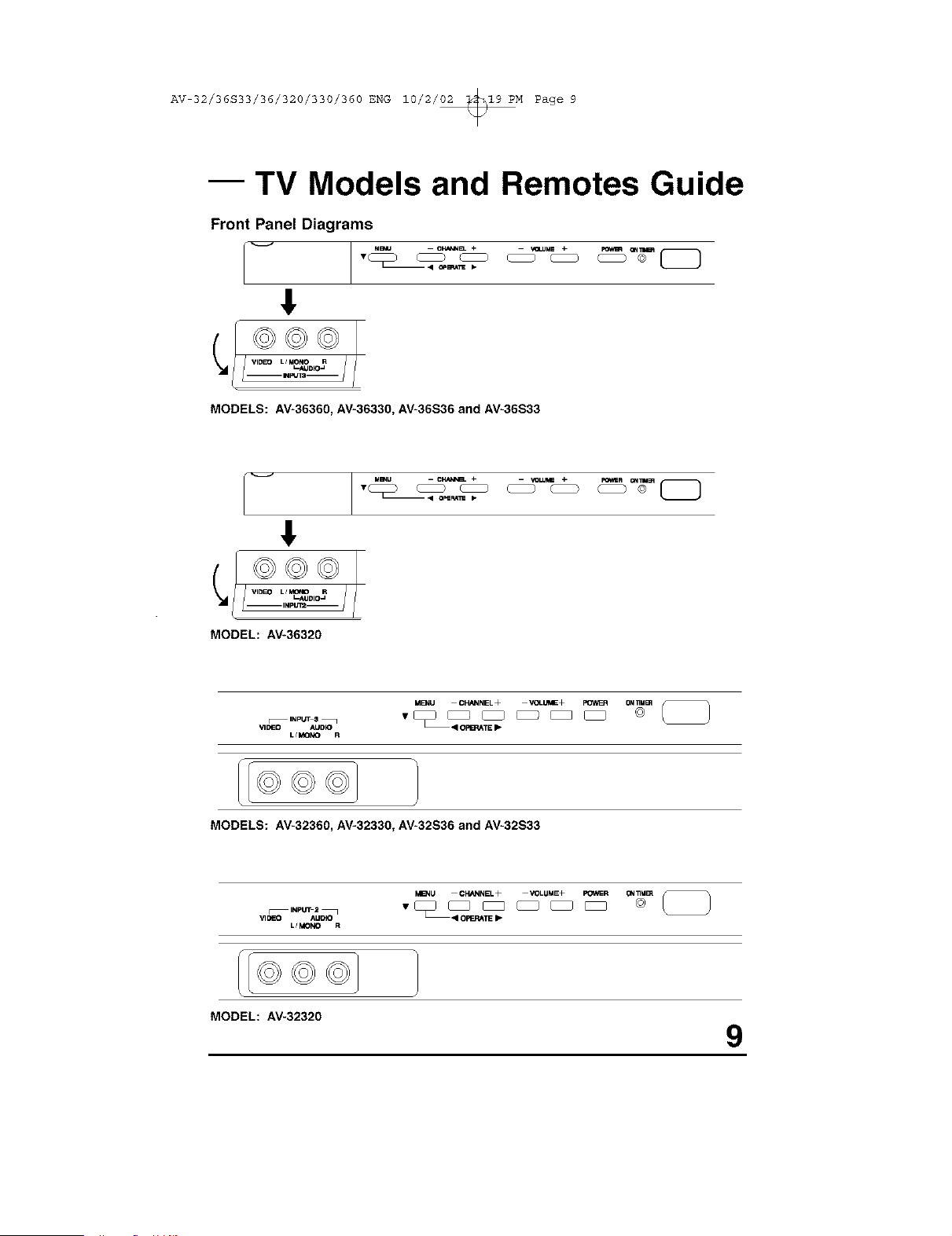
Front Panel Diagrams
!
©©©
J
MODELS: AV-36360, AV-36330, AV-36S36 and AV-36S33
_ Mmu - CNAmB_ + - VOLU_ +
m • O_SF_S p
©©©
MODEL: AV-36320
MEnU CHANNEL+ "4OLd+ _ 0=4_U_
VlOEO AUDR) II OFI_TE I_,
L/MONO R
MODELS: AV-32360, AV-32330, AV-32S36 and AV-32S33
M_NU CHANNEL+ VOLUME+ POWER ON_M_ _
VIDEO AUDIO I OPERATE _.
L/MONO R
I©©©
MODEL: AV-32320
9
AV 32/36S33/36/320/330/360 ENG 10/2/02 _19 PM Page i0
TV Models and Remotes Guide--
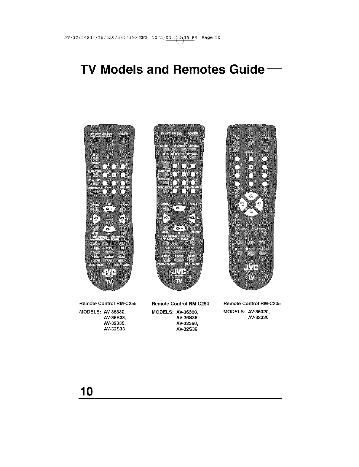
Remote Control RM=C255
Remote Control RM-C254
MODELS: AV-36330, MODELS: AV-36360,
AV-36S33_ AV-36S36_
AV-32330, AV-32360,
AV-32S33 AV-32S36
Remote Control RM=C205
MODELS: AV_36320,
AV-32320
10
AV 32/36S33/36/320/330/360 ENG 10/2/02 _19 PM Page ii
I
Getting Started
These quick setup pages will provide you, in three easy steps, with the basic information you
need to begin using your new television right away. This information includes basic instructions
on operating your remote control, making a simple cable/antenna and optional VCR connection
and, finally, information on programming your television's Auto Tuner.
If you have questions, or for more detailed information on any of these steps, please consult
other sections of this manual.
Step One -The Remote Control
The remote control is the key to operating your television's many great features. Before you
can operate your remote control, you first need to install the batteries (included).
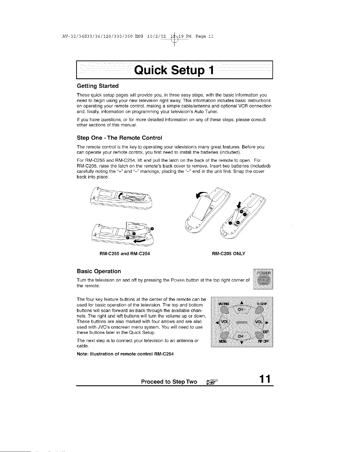
For RM-C255 and RM-C254, lift and pull the latch on the back of the remote to open. For
RM-C205, raise the latch on the remote's back cover to remove. Insert two batteries (included)
carefully noting the "+" and "-" markings, placing the '-" end in the unit first. Snap the cover
back into place.
RM-C255 and RM-C254 RM-C205 ONLY
Basic Operation
Turn the television on and off by pressing the POWERbutton at the top right corner of
the remote,
The four key feature buttons at the center of the remote can be
used for basic operation of the television. The top and bottom
buttons will scan forward an back through the available chan-
nels. The right and left buttons will turn the volume up or down.
These buttons are also marked with four arrows and are also
used with JVC's onscreen menu system. You will need to use
these buttons later in the Quick Setup.
The next step is to connect your television to an antenna or
cable.
Note: Illustration of remote control RM-C254
Proceed to Step Two _ 11
AV 32/36S33/36/320/330/360 ENG 10/2/02 _19 PM Page 12
I
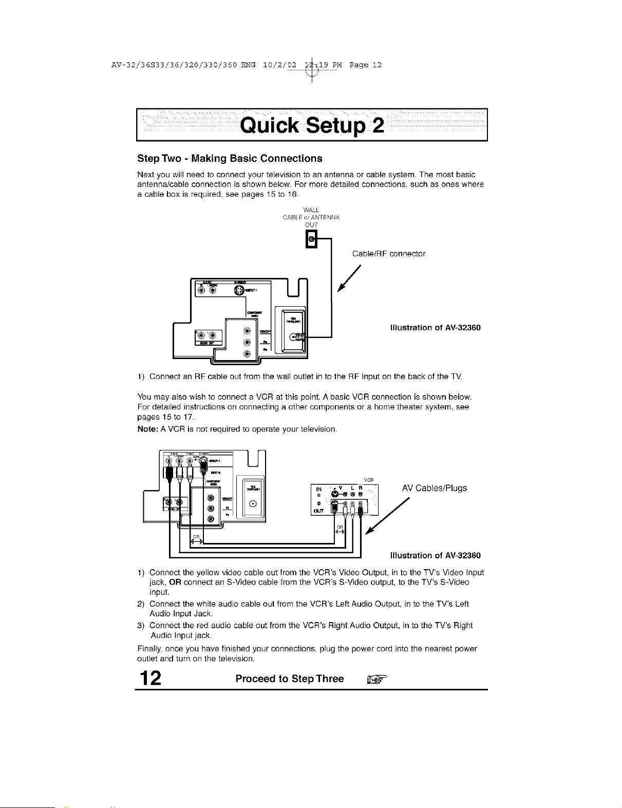
Step Two - Making Basic Connections
Next you will need to connect your television to an antenna or cable system.The most basic
antennaJcableconnection is shown below. For more detailed connections, such as ones where
a cable box is required,see pages 15 to 16.
WALL
CABL or ANIENNA
OUI
B-
Cable/R F connector
/
1) Connect an RF cable out from the wall outlet in to the RF input on the back of the TV.
Illustration of AV-32360
You may also wish to connect a VCR at this point. A basic VCR connection is shown below.
For detailed instructions on connecting a other components or a home theater system, see
pages 15 to 17.
Note: A VCR is not required to operate your television.
VCR
I I N v_V L R I AV Cables/Plugs
• I Illustration of AV-32360
t) Connect the yellow video cable out from the VCR's Video Output, in to the TV's Video input
jack, OR connect an S-Video cable from the VCR's S-Video output, to the TV's S-Video
input.
2) Connect the white audio cable out from the VCR's Left Audio Output, in to the TV's Left
Audio Input Jack.
3) Connect the red audio cable out from the VCR's Right Audio Output, in to the TV's Right
Audio input jack.
Finally, once you have finished your connections, plug the power cord into the nearest power
outlet and turn on the television.
12 Proceed to Step Three
AV 32/36S33/36/320/330/360 ENG 10/2/02 _19 PM Page 13
I
Step Three-The Plug In Menu
When you turn your television on for the first time the Plug In Menu will appear. This menu sets
some of the basic settings for your television. A complete description of the Plug In Menu can
be found starting on page 25. We recommend you complete the Piug In Menu items before you
start using your television. But to begin watching your television right away you only need to
run the Auto Tuner Setup. This lets your television learn the channels it is able to receive. To
run the Auto Tuner Setup follow the steps below.
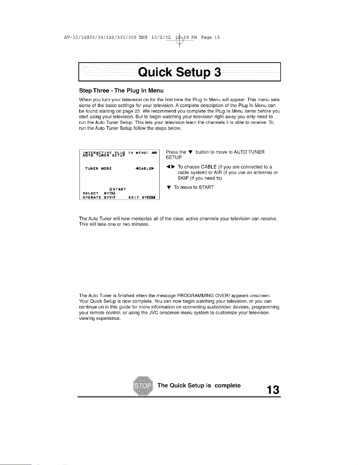
INTERACTIVE PLUG IN MENU>
AUTO TUNER SETUP
TUNER MODE <CABLE"
[]START
SELECT BYD[
OPERATE BY[][] EXIT ByI_3B_I
Pressthe • buttontomovetoAUTOTUNER
SETUP
• • To choose CABLE (if you are connected to a
cable system) or AIR (if you use an antenna) or
SKIP (if you need to)
• To move to START
The Auto Tuner will now memorize all of the clear, active channels your television can receive.
This will take one or two minutes.
The Auto Tuner is finished when the message PROGRAMMING OVER! appears onscreen.
Your Quick Setup is now complete. You can now begin watching your television, or you can
continue on in this guide for more information on connecting audio/video devices, programming
your remote control, or using the JVC onscreen menu system to customize your television
viewing experience.
The Quick Setup is complete 13
AV 32/36S33/36/320/330/360 ENG 10/2/02 _19 PM Page 14
Connections
Cable and VCR Connections
There are three basic types of antenna or cable connections:
• If you nave an antenna or have a cable system that does not require you use a cable box
to select channels, please refer to Diagram #1.
• If you have a cable system that requires the use of a cable box to access all the channels,
olease refer to Diagram #2. If you cannot operate your Picture-In-Picture function using
Diagram #2, try [he connection shown in Diagram #3. It is possible your cable box allows
the signal of only one channel at a time to be sent to your television.
• If you have a cable system that reeuires the use of a cable box to access certain premium
ccenae[s but not '_basic" cable channels, please refer to Diagram #3.
• For your conventence coanectton to a VCR Esalso shown in the following diagrams. A
VCR is not necessary for operation of the television or Picture-In*Picture (PIP) func-
tion. You may omit the VCR from your connections if you w sn.
• For instructions on connecting a VCR only, please see the Quick Setup on page 12,
• For informauon on umng PIP, ptease see page 47.
• The PIP feature is available on AV-36360, AV-36S36, AV-32360 and AV-32S36 models
only.
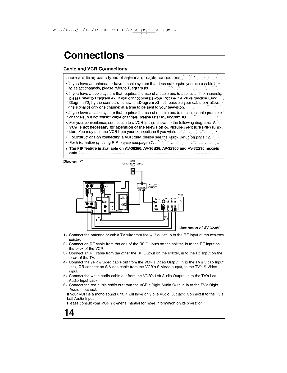
Diagram #1
ou!
I SPLICER
VCR
_eo I
" I I illustration of AV-32360
t) Connect the antenna or cable TV wire from the wall outlet, in to the RF Input of the two-way
splitter.
2) Connect an RF cable from the one of the RF Outputs on the splitter, in to the RF Input on
the back of the VCR.
3) Connect an RF cable from the other the RF Output on the splitter, in to the RP Input on the
back of the TV.
4) Connect the yellow video cable out from the VCR's Video Output, in to the TV's Video Input
jack, OR connect an S-Video cable from the VCR's S-Video output, to the TV's S-Video
input
5) Connect the white audio cable out from the VCR's Left Audio Output, in to the TV% Left
Audio Input Jack,
6) Connect the red audio cable out from the VCR's Right Audio Output, in to the TV% Right
Audio Input jack,
• If your VCR is a mono sound unit it will have only one Audio Out jack, Connect it to the TV%
Left Audio Input,
• Please consult your VCR's owner's manual for more information on its operation,
14
AV 32/36S33/36/320/330/360 ENG 10/2/02 _19 PM Page 15
Connections
Cable and VCR Connections - Continued
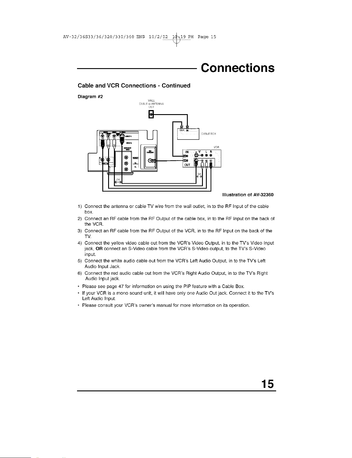
Diagram #2
CA!q E _/q_ [NNA
OU_
Illustration of AV-32360
t) Connect the antenna or cable TV wire from the wall outlet, in to the RF Input of the cable
box.
2) Connect an RF cable from the RF Output of the cable box, in to the RF input on the back of
the VCR.
3) Connect an RF cable from the RF Output of the VCR, in to the RF input on the back of the
TV.
4) Connect the yellow video cable out from the VCR's Video Output, in to the TV's Video input
jack, OR connect an S-Video cable from the VCR's S-Video output, to the TV's S-Video
input.
5) Connect the white audio cable out from the VCR's Left Audio Output, in to the TV's Left
Audio input Jack.
6) Connect the red audio cable out from the VCR's Right Audio Output, in to the TV's Right
Audio input jack.
• Please see page 47 for information on using the PiP feature with a Cable Box.
• If your VCR is a mono sound unit, it will have only one Audio Out jack. Connect it to the TV's
Left Audio input.
• Please consult your VCR's owner's manual for more information on its operation.
15
AV 32/36S33/36/320/330/360 ENG 10/2/02 _19 PM Page 16
Connections
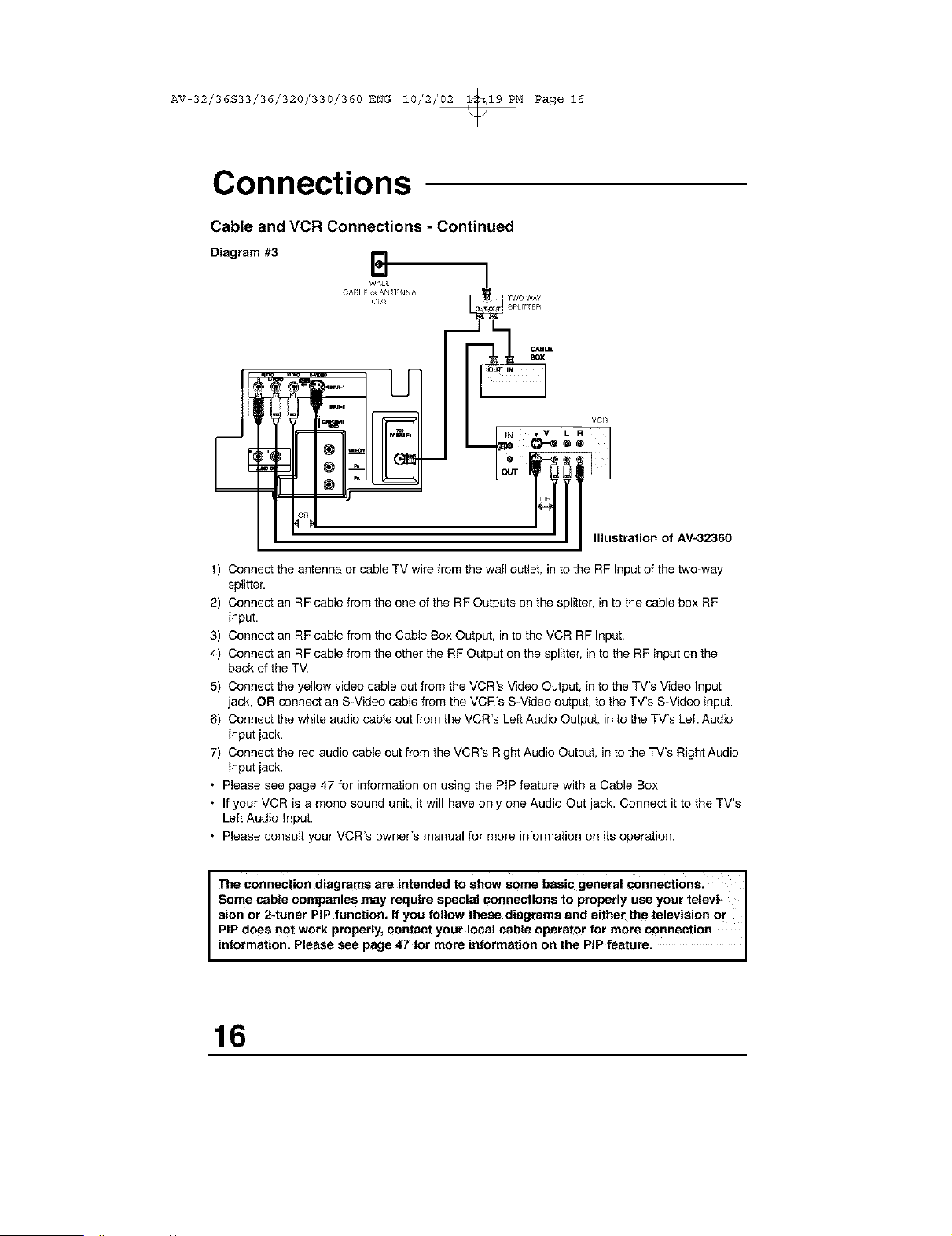
Cable and VCR Connections - Continued
Diagram #3
B
WALL
CABLE o_AN_ ENNA
OUT
U
TWO WAY
SPtI_ER
VCR
R
°1
Illustration of AV-32360
t) Connect the antenna or cable TV wire from the wall outlet, in to the RF Input of the two-way
splitter.
2) Connect an RF cable from the one of the RF Outputs on the splitter, in to the cable box RF
input.
3) Connect an RF cable from the Cable Box Output, in to the VCR RF Input.
4) Connect an RF cable from the other the RF Output on the splitter, in to the RF input on the
back of the TV.
5) Connect the yellow video cable out from the VCR's Video Output, in to the TV's Video Input
jack, OR connect an S-Video cable from the VCR's S-Video output, to the TV's S-Video input.
6) Connect the white audio cable out from the VCR's Left Audio Output, in to the TV's Left Audio
input jack.
7) Connect the red audio cable out from the VCR's Right Audio Output, in to the TV's Right Audio
Input jack.
• Please see page 47 for information on using the PiP feature with a Cable Box.
• If your VCR is a mono sound unit, it will have only one Audio Out jack. Connect it to the TV's
Left Audio input.
• Please consult your VCR's owner's manual for more information on its operation.
I The connection diagrams are intended to show some basic general connections, I
Some cable companies may require special connections to properly use your televi-
sion or 2-tuner PIP function= If you follow these diagrams and either the television or I
PIP does not work properly, contact your local cable operator for more connection
nformat on, P ease see page 47 for more nformat on on the P P feature.
16
AV 32/36S33/36/320/330/360 ENG 10/2/02 _19 PM Page 17
Connections
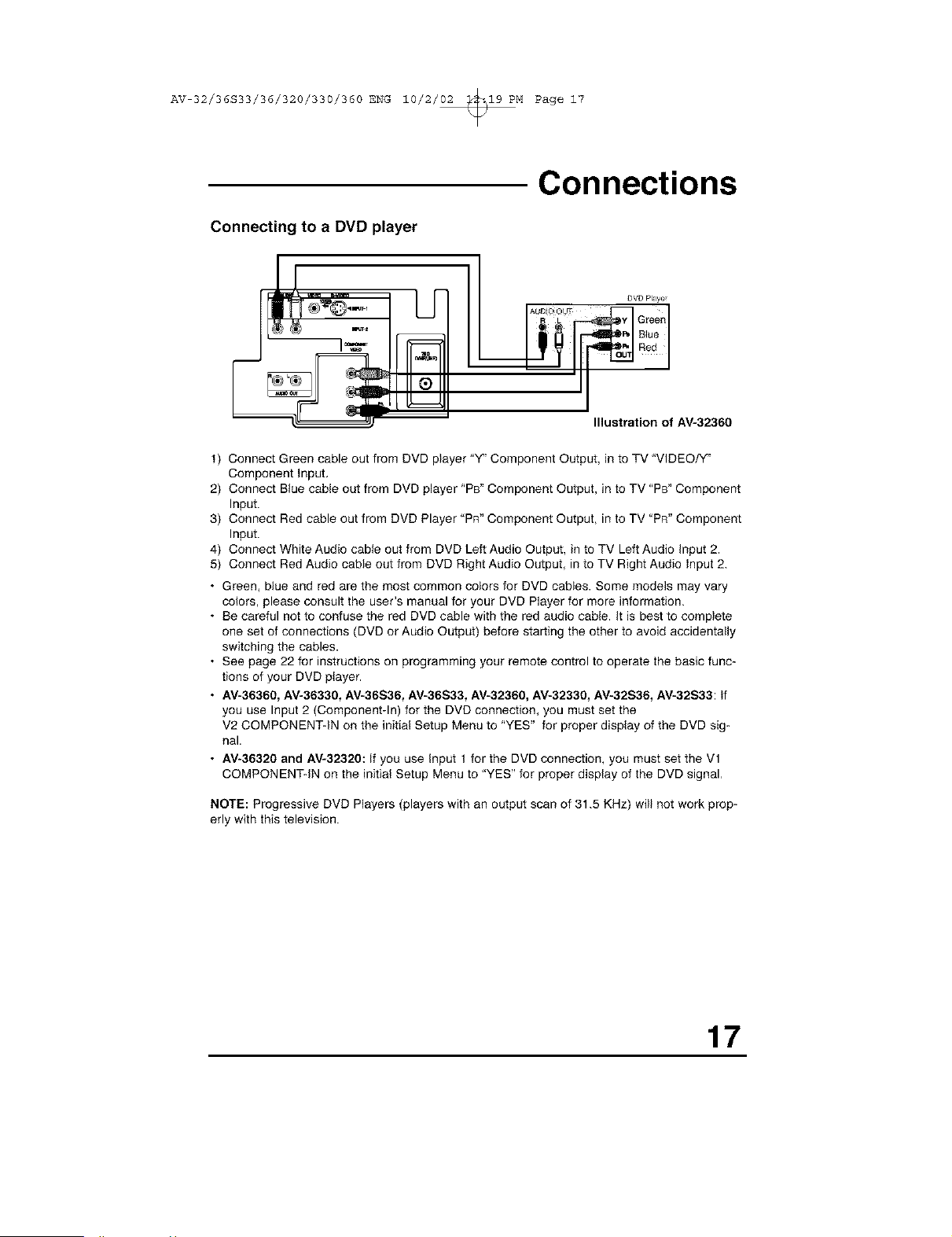
Connecting to a DVD player
DVD Playe_
R L _ Green
_ BIue
Bed
Illustration of AV-32360
t) Connect Green cable out from DVD player "Y_'Component Output, in to TV "VIDEO/'{'
Component Input,
2) Connect Blue cable out from DVD player 'PB" Component Output, in to TV 'PB" Component
Input.
3) Connect Red cable out from DVD Player "PR" Component Output, in to TV "PR" Component
Input.
4) Connect White Audio cable out from DVD Left Audio Output, in to TV Left Audio input 2.
5) Connect Red Audio cable out from DVD Right Audio Output, in to TV Right Audio input 2.
• Green, blue and red are the most common colors for DVD cables. Some models may vary
colors, please consult the user's manual for your DVD Player for more information.
• Be careful not to confuse the red DVD cable with the red audio cable. It is best to complete
one set of connections (DVD or Audio Output) before starting the other to avoid accidentally
switching the cables.
• See page 22 for instructions on programming your remote control to operate the basic func-
tions of your DVD player.
• AV-36360, AV-36330, AV-36S36, AV-36S33, AV-32360, AV_32330, AV-32S36, AV-32S33: If
you use Input 2 (Component-In) for the DVD connection, you must set the
V2 COMPONENT-IN on the initial Setup Menu to 'YES" for proper display of the DVD sig-
nal.
• AV-36320 and AV-32320: If you use Input t for the DVD connection, you must set the Vl
COMPONENT-IN on the initial Setup Menu to "YES" for proper display of the DVD signal,
NOTE: Progressive DVD Players (players with an output scan of 31.5 KHz) will not work prop-
erly with this television.
17
AV 32/36S33/36/320/330/360 ENG 10/2/02 _19 PM Page iS
Connections
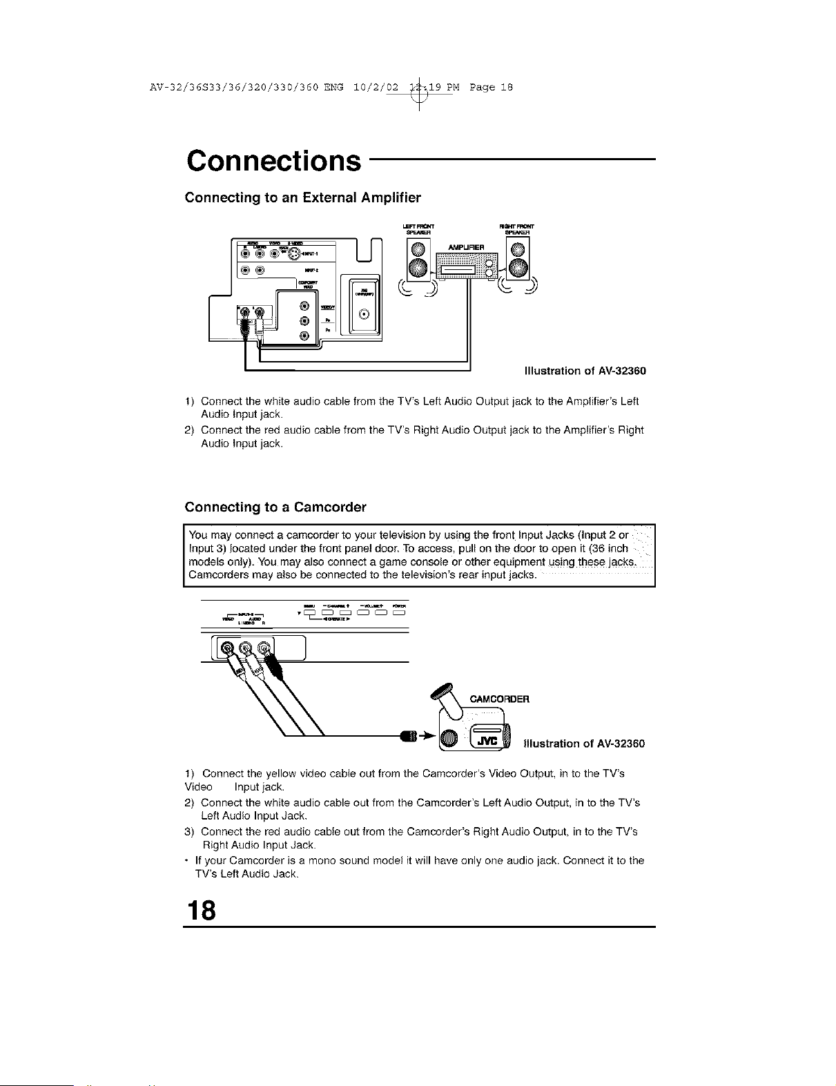
Connecting to an External Amplifier
LSFTFF_rr FImITFR0_T
__IPURER
Illustration of AV-32360
t) Connect the white audio cable from theTV's Left Audio OutputjacktotheAmplifier's Left
Audiolnputjack.
2) Connect the red audio cable from theTV's Right Audio Output jack totheAmplifier's Right
AudioInputjack.
Connecting to a Camcorder
You may connect a camcorder to your television by using the front Input Jacks (input 2 or
Input 3) located under the front panel door. To access, pull on the door to open it (36 inch
models only). You may also connect a game console or other equipment using these jacks.
Camcordere may a so be connected to the te ev s on e rear nput acks.
ustr.tono,_
t) Connect the yellow video cable out from the Camcorder's Video Output, in to the TV's
Video Input jack.
2) Connect the white audio cable out from the Camcorder's Left Audio Output, in to the TV's
Left Audio Input Jack.
3) Connect the red audio cable out from the Camcorder's Right Audio Output, in to the TV's
Right Audio Input Jack.
• If your Camcorder is a mono sound model it will have only one audio jack. Connect it to the
TV's Left Audio Jack.
18
AV 32/36S33/36/320/330/360 ENG 10/2/02 _19 PM Page 19
Remote Control
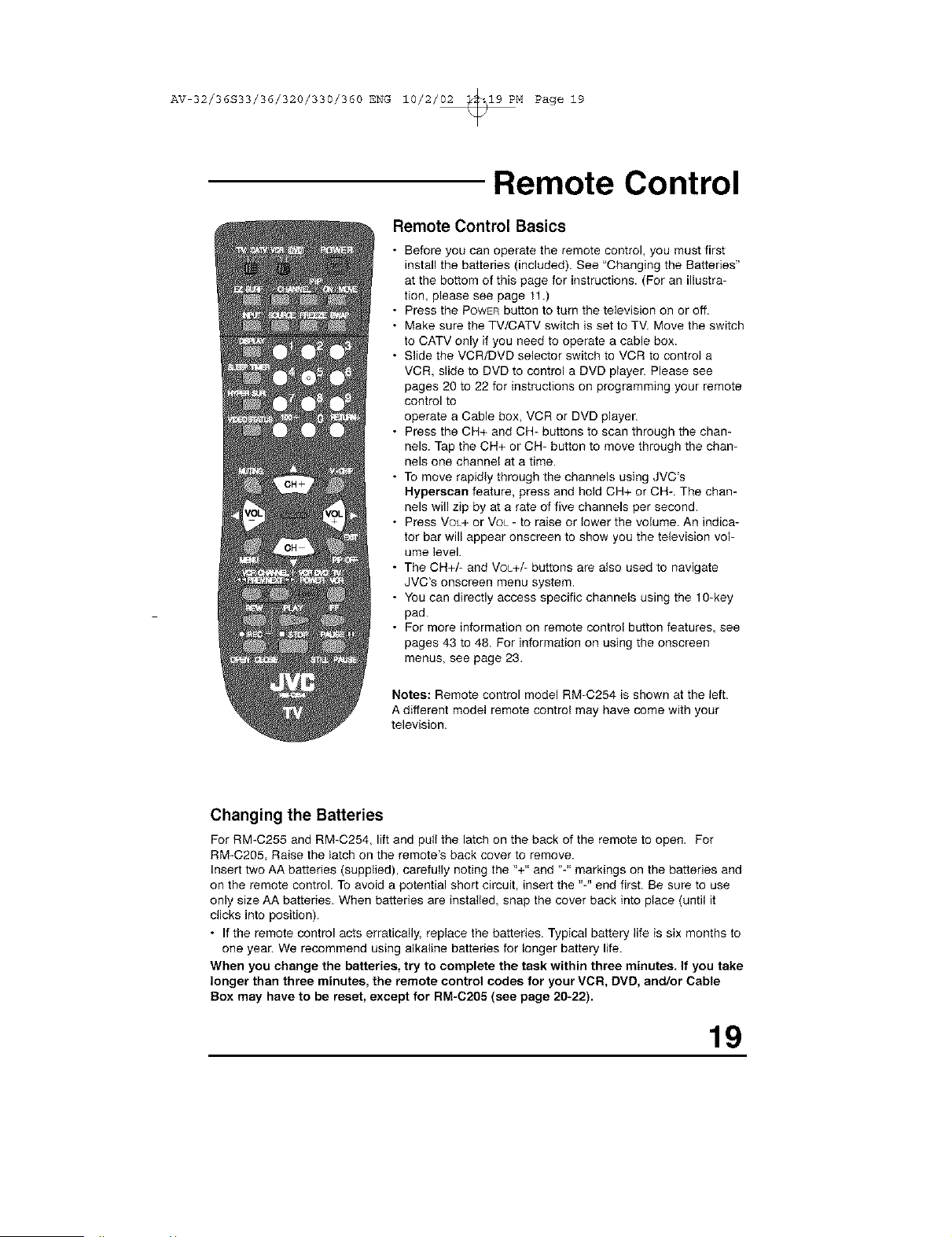
Remote Control Basics
• Before you can operate the remote control, you must first
install the batteries (included). See "Changing the Batteries"
at the bottom of this page for instructions. (For an illustra-
tion, please see page 11.)
• Press the POWERbutton to turn the television on or off.
• Make sure the TV/CATV switch is set to TV. Move the switch
to CATV only if you need to operate a cable box.
• Slide the VCR/DVD selector switch to VCR to control a
VCR, slide to DVD to control a DVD player. Please see
pages 20 to 22 for instructions on programming your remote
control to
operate a Cable box, VCR or DVD player.
• Press the CH+ and CH- buttons to scan through the chan-
nels. Tap the CH+ or CH- button to move through the chan-
nels one channel at a time.
• To move rapidly through the channels using JVC's
Hyperscan feature, press and hold CH+ or CH-. The chan-
nels will zip by at a rate of five channels per second.
• Press VOL+ or Vot_- to raise or lower the volume. An indica-
tor bar will appear onscreen to show you the television vol-
ume level.
• The CH+/- and VOL+/- buttons are also used to navigate
JVC's onscreen menu system.
• You can directly access specific channels using the 10-key
pad.
• For more information on remote control button features, see
pages 43 to 48. For information on using the onscreen
menus, see page 23.
Notes: Remote control model RM-C254 is shown at the left.
A different model remote control may have come with your
television.
Changing the Batteries
For RM-C255 and RM-C254, lift and pull the latch on the back of the remote to open. For
RM-C205, Raise the latch on the remote's back cover to remove.
Insert two AA batteries (supplied), carefully noting the "+" and "-" markings on the batteries and
on the remote control. To avoid a potential short circuit, insert the "-" end first. Be sure to use
only size AA batteries. When batteries are installed, snap the cover back into place (until it
clicks into position).
• If the remote control acts erratically, replace the batteries. Typical battery life is six months to
one year. We recommend using alkaline batteries for longer battery life.
When you change the batteries, try to complete the task within three minutes. If you take
longer than three minutes, the remote control codes for your VCR, DVD, and/or Cable
Box may have to be reset, except for RM-C205 (see page 20-22).
19
AV 32/36S33/36/320/330/360 ENG 10/2/02 _19 PM Page 20
Remote Programming
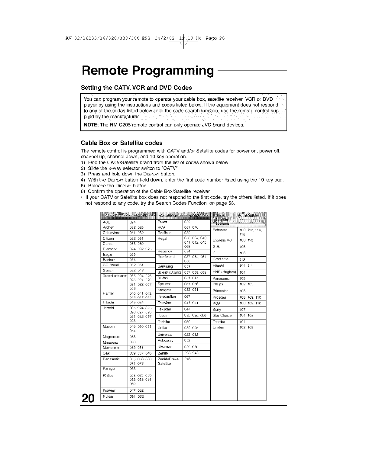
Setting the CATV, VCR and DVD Codes
J Youcan programyour remote to operate your cable box, satellite receiver, VCR or DVD
player byusing the instructions and codes listed below. Ifthe equipment does not respond J
to any of the codes listed below or to the code search function, use the remote contr0 SUp-
plied bythe manufac!urer_
NOTE: The RM-C205 remote eontro can on y oporate JVC-brand dev ces.
Cable Box or Satellite codes
The remote control is programmed with CATV and/or Satellite codes for power on_ power off,
channel up, channel down_ and 10 key operation.
t) Find the CATV/Satetlite brand from the list of codes shown below.
2) Slide the 2-way selector switch to 'CATV".
3) Press and hold down the DISPLAYbutton.
4) With the DISPLAYbutton held down, enter the first code number listed using the 10 key pad.
5) Release the DISPLAYbutton.
6) Confirm the operation of the Cable Box/Satellite receiver.
• If your CATV or Satellite box does not respond to the first code, try the others listed. If it does
not respond to any code, try the Search Codes Function, on page 53.
20
ABC
Archer
Cableview
C}iizen
Cu_lis
D}amond
Eagle
Eastern
GC Brand
Gemini
General ns_rume_t
Hamlin
Hitachi
Jerrold
Macom
Magnavox
Memorex
Mov}elime
Oak
Panason}c
Paragon
Philips
Pioneer
Pulsar
O24
032,025
05%032
022,051
058,059
024,032025
029
034
032,051
022,043
065,024,025
026, 027,020
021,022057
023
040,041042,
045,058064
049,024
065,024025,
026,027020,
021,022057,
023
049,050051,
054
033
O30
032,051
039,037048
055,056060,
07t,073
063
028,029030,
052,053031,
069
047,062
051 032
Regency
Rembrandt
Samsung
Scientific A_anta
SLMark
Sprucer
SIargate
Telecaption
Teleview
Texscan
Tocom
Toshiba
Un}ka
Universal
Videoway
Vlewstar
Zenith
Zenith/Drake
Satellile
032
061_070
032
058,064,040
041,042 045
O68
034
037,032051
O38
051
057,058 059
051,047
051 056
032 051
O67
047 051
044
035 036066
O50
032 025
022 032
O52
029 030
063 046
046
Echostar
Expless VU
GE
GI
Gradiente
Hitachi
HNS (Hughes}
Panasonic
Philips
Primestal
Proscan
RCA
Sony
Slat Choice
Toshiba
Uniden
100, I13,114
115
100 113
106
108
112
I04 tll
I04
105
102 103
108
106 109110
106 109110
107
104 108
101
102 103
AV 32/36S33/36/320/330/360 ENG 10/2/02 _19 PM Page 21
Remote Programming
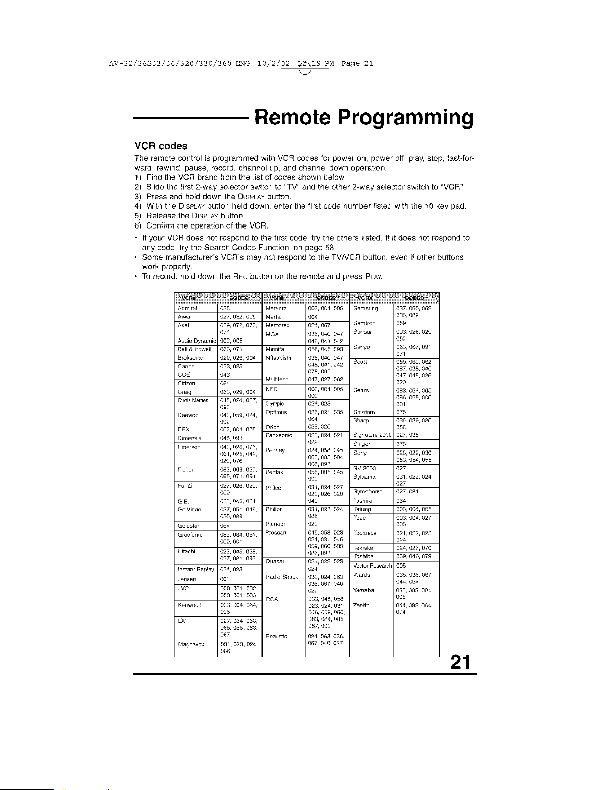
VCR codes
The remote control is programmed with VCR codes for power on, power off, play, stop, fast-for-
ward, rewind, pause, record, channel up, and channel down operation.
t) Find the VCR brand from the list of codes shown below.
2) Slide the first 2-way selector switch to "TV" and the other 2-way selector switch to 'VCR".
3) Press and hold down the DISPLAYbutton.
4) With the DISPLAYbutton held down, enter the first code number listed with the t0 key pad.
5) Release the DISPLAYbutton.
6) Confirm the operation of the VCR,
• If your VCR does not respond to the first code, try the others listed. If it does not respond to
any code, try the Search Codes Function, on page 53,
• Some manufacturer's VCR's may not respond to the TVNCR button, even if other buttons
work properly.
• To record, hold down the RECbutton on the remote and press PLAY.
AdmiraJ 035
Aiwa 027, 032, 095
Akal 029, 072, 073,
074
Audio Dynamic 003, 005
Bell & HoweJl 063, 071
Bloksonic 020, 026, 094
Canon 023, 025
CCE 043
C_tlzea 064
Ctalg 063, 029, 064
CurtisMathes 045, 024, 027,
093
Daewoo 043, 059, 024,
092
DBX 003, 004 005
DimensJa 045, 093
Emelson 043, 026, 077,
061,025 042,
020, 078
I _sher 063, 068, 067,
065, 071 091
luna_ 027, 026, 020,
000
GE 033, 045 024
Go Video 037, 051,049,
050, 089
Goldstar 064
Grad_ente 083, 084, 081,
000, 001
Hitach_ 023, 045, 058,
027, 081,093
instant Replay 024,023
Jensen 003
JVC 000, 001 r002,
003, 004, 005
Kenwood 003, 004, 064,
005
LXI 027, 064, 058,
065, 066, 063,
067
Magnavox 031,023, 024,
088
Marat]tz
Marta
Memorex
MGA
M_no_ta
Mffsublsh_
Muff_tech
NEC
Oymp_
Optimus
Orion
Panasonic
Penney
Pentax
Ph_lco
Ph_l_ps
Pioneer
Proscan
Quasat
Radio Shack
RCA
Reali_ic 024063,036,
067040,027
003, 004 005
O64
024, 067
038, 040, 047,
048, 041 042
058, 045 093
038, 040, 047,
048, 041,042,
078, 090
047, 027 062
003, 004, 005,
000
024, 023
028, 021,035,
064
026, 020
023, 024, 021,
022
024, 058, 045,
063, 003, 004,
005, 093
058, 005, 045,
093
031,024, 027,
023, 026, 020,
043
031,023, 024,
086
023
045, 058, 023,
024, 031,048,
059, 060, 033,
087, 093
021,022, 023,
024
033, 024, 063,
036, 067, 040,
027
033, 045, 058,
023, 024, 031,
046, 059, 060,
083, 084, 085,
087, 093
Samsung 037, 060, 062,
033 089
Samtlon 089
Sansui 003, 026, 020,
052
Sanyo 063, 067, 091,
071
Scott 059, 060, 062,
067, 038, 040,
047, 048, 026,
020
Sears 063, 064, 065,
066 058, 000,
001
Shlntom 075
Sharp 035, 036, 080,
088
S_gnature 200C 027 035
S_nger 075
Sony 028, 029, 030,
053 054, 055
SV 2000 027
Sylvania 031 023, 024,
027
Symphonic 027 081
_shlro 064
Stung 003 004, 005
Teac 003, 004, 027,
005
Technics 021,022, 023,
024
Teknlka 024 027, 070
Toshiba 059 046, 079
Vectol F{esearcl 005
Wards 035, 036, 067,
044 064
Yamaha 063, 003, 004,
005
Zenith 044, 082, 064,
094
21
AV 32/36S33/36/320/330/360 ENG 10/2/02 _19 PM Page 22
Remote Programming
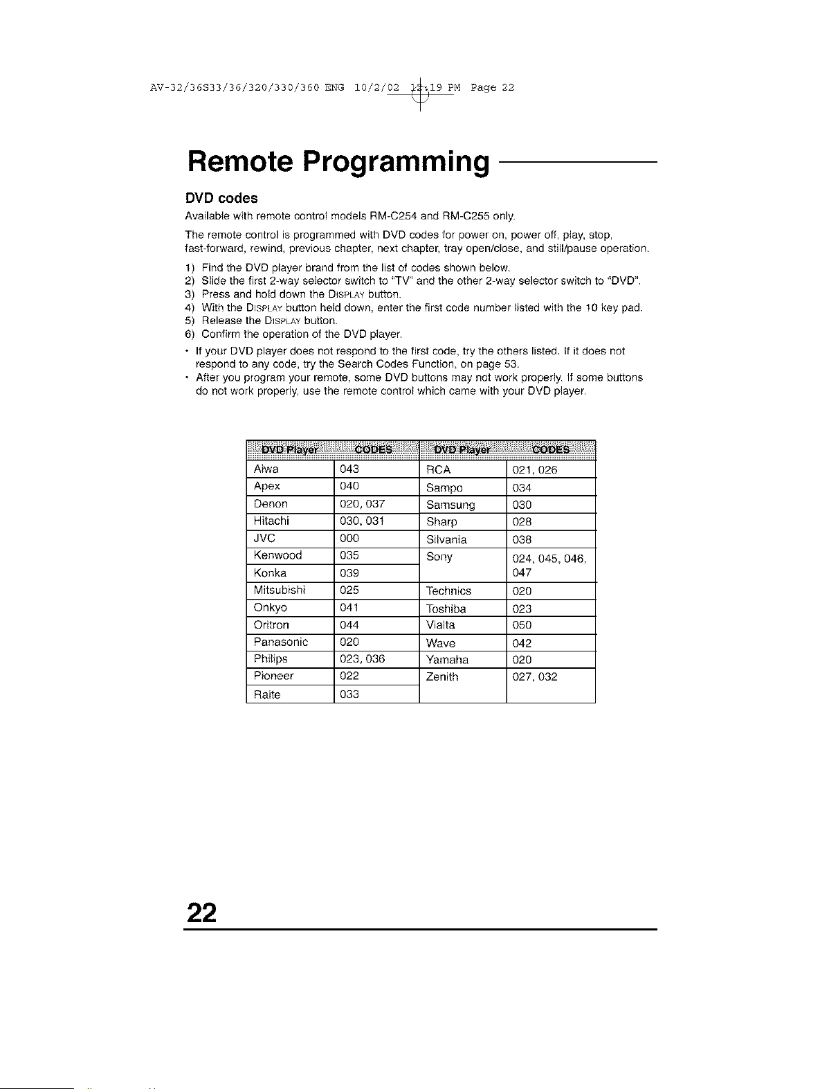
DVD codes
Available with remote control models RM-C254 and RM-C255 only.
The remote control is programmed with DVD codes for power on, power off, play, stop,
fast4orward, rewind, previous chapter, next chapter, tray open/close, and still/pause operation.
t) Find the DVD player brand from the list of codes shown below.
2) Slide the first 2-way selector switch to "TV" and the other 2-way selector switch to 'DVD".
3) Press and hold down the DISPLAYbutton.
4) With the DISPLAYbutton held down, enter the first code number listed with the t0 key pad.
5) Release the DISPLAYbutton.
6) Confirm the operation of the DVD player.
• If your DVD player does not respond to the first code, try the others listed, If it does not
respond to any code, try the Search Codes Function, on page 53.
• After you program your remote, some DVD buttons may not work properly. If some buttons
do not work properly, use the remote control which came with your DVD player.
Aiwa
Apex
Denon
Hitachi
JVC
Kenwood
Konka
Mitsubishi
Qnkyo
Oritron
Panasonic
Philips
Pioneer
Raite
O43
O40
020,037
030,031
000
O35
O39
O25
041
O44
O2O
023,036
O22
O33
RCA
Sampo
Samsung
Sharp
Silvania
Sony
Technics
Toshiba
Vialta
Wave
Yamaha
Zenith
021,026
034
030
028
038
024, 045, 046,
O47
02O
023
O5O
O42
O2O
027, 032
22
AV 32/36S33/36/320/330/360 ENG 10/2/02 _19 PM Page 23
Onscreen Menus
Using the Guide
Certain symbols are used throughout this guide to help you learn about the features of your
new television. The ones you will see most frequently are:
AT Up and Down arrows mean press the OH+ or OH- buttons. Pressing the CH+ or OH- but-
tons let you:
• Move vertically in a main menu screen
• Move through a submenu screen
• Move to the next letter, number, or other choice in a submenu
• Back up to correct an error
• Scan through TV channels (when not in a menu screen)
41• Left and right arrows mean press the VOLUME+or VOLUME-buttons to move left or right
to:
• Select a highlighted menu item
• Select an item in a submenu
• Select numbers in certain menu options
• Turn the volume up or down (when not in a menu screen)
(_ The "Press Button" icon means you should press the button named on your remote con-
tro!. (Button names appear in SMALLCAPITALLETTERS.)
[_ The 'Helping Hand" icon points to the highlighted or selected item in
a menu.
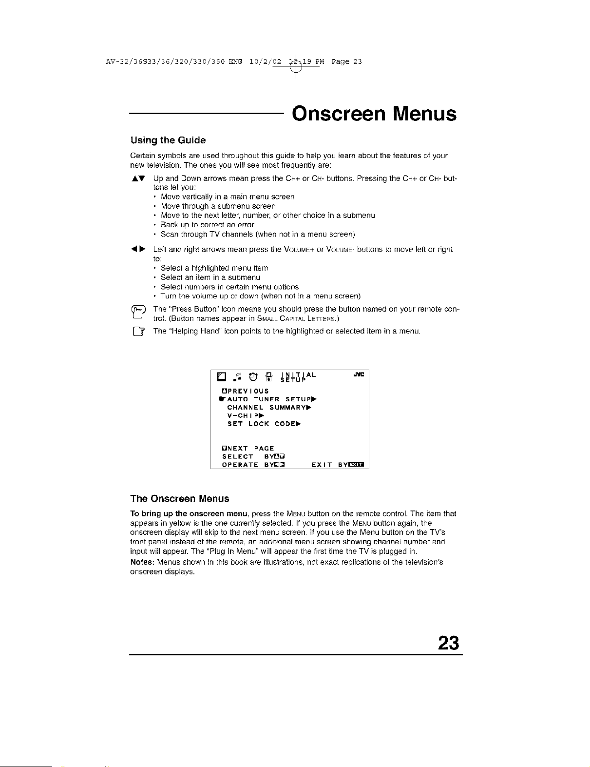
[] _ _ _ INITIAL
SETUP
OPREVIOUS
• AUTO TUNER SETUP,
CHANNEL SUMMARY,
V-CHIP,
SET LOCK CODE,
QNEXT PAGE
SELECT BYD_
OPERATE BYI_[] EXIT Byl_]il
The Onscreen Menus
To bring up the onscreen menu, press the MENHbutton on the remote control. The item that
appears in yellow is the one currently selected. If you press the MENU button again, the
onscreen display will skip to the next menu screen. If you use the Menu button on the TV's
front panel instead of the remote, an additional menu screen showing channel number and
input will appear. The "Plug In Menu" will appear the first time the TV is plugged in.
Notes: Menus shown in this book are illustrations, not exact replications of the television's
onscreen displays.
23
AV 32/36S33/36/320/330/360 ENG 10/2/02 _19 PM Page 24
Onscreen Menus
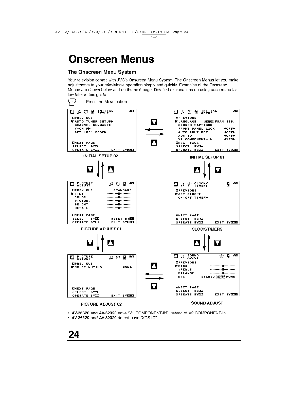
The Onscreen Menu System
Your teIevision comes with JVC's Onscreen Menu System. The Onscreen Menus let you make
adjustments to your television's operation simply and quickly. Examples of the Onscreen
Menus are shown below and on the next page. Detailed explanations on using each menu fol-
low later in this guide.
Press the MENUbutton
[] _ _ _ INITIAL
SETUP
[]PREVIOUS
• AUTO TUNER SETUP"
CHANNEL SUMMARY,
V--CHIP,
SET LOCK CODE,
[]NEXT PAGE
SELECT BYt3[
OPERATE BYI_[ EXIT BylaW01
INITIAL SETUP 02
[] PICTURE ._ _ _
ADJUST
[]PREVIOUS STANDARD
• TINT .......... II ..........
COLOR .......... II ..........
PICTURE .......... II ..........
BRIGHT .......... II ..........
DETAIL .......... II ..........
[]
[]
m_
[] _ _ _ INITIAL
SETUP
[]PREVIOUS
"LANGUAGE
iiii_!_i_: FRAN. ESP.
CLOSED CAPTION,
FRONT PANEL LOCK "OFF"
AUTO SHUT OFF ,OFF,
XDS ID "OFF"
V2 COMPONENT--IN ,YES,
ONEXT PAGE
SELECT BY[[
OPERATE BYI_ EXIT Byl_3_l
INITIAL SETUP 01
[] °It[]
[] ._ _ CLOCK/
TIMERS
[]PREVIOUS
• SET CLOCK"
ON/OFF TIMER II*
ONEXT PAGE
SELECT BYt30 RESET ByIOI
OPERATE BYI_ EXIT ByI_3g01
PICTURE ADJUST 01
o11o
[] PICTURE ._ tb _
ADJUST
OPREVIOUS
• NOISE MUTING ,ON,
[]NEXT PAGE
SELECT BYt3_
OPERATE BYE][] EXIT Byl_3g01
[]
[]
ONEXT PAGE
SELECT BY[O
OPERATE BYE}CI EXIT ByI_
CLOCK/TIMERS
,,to
[] ._ SOUND _ _ ._
ADJUST
[]PREVIOUS
• BASS .......... II ..........
TREBLE .......... II ..........
BALANCE .......... II ..........
MTS STEREOIIIi_AP:iilMONO
_NEXT PAGE
SELECT BY!_[
OPERATE BY_Q EXIT By_I
PICTURE ADJUST 02
SOUND ADJUST
• AV-36320 and AV-32320 have "Vl COMPONENT-IN" instead of V2 COMPONENT-IN.
• AV-36320 and AV-32320 do not have "XDS iD".
24
AV 32/36S33/36/320/330/360 ENG 10/2/02 _19 PM Page 25
Plug In Menu
Introduction
The Plug In Menu comes up automatically when you first turn on the TV after plugging it in.
The Plug In Menu helps you to get your TV ready to use by letting you set your preferences
for:
• The Language in which you want the onscreen menus to appear,
• The Auto Tuner Setup of which channels you wish to receive,
• Setting the TV's clock to the correct time so your timer functions will work properly.
Descriptions of each of the Plug In Menu features appear on this page and the next. We rec-
ommend you complete the Plug In Menu setup first so your TV is set up just the way you want,
right away.
Language
You can choose to view your onscreen menus in three languages: English (ENG.), French
(FRE.), or Spanish (ESP.).
(_ Press the MENUbutton
AV To LANGUAGE
41• To choose a language
_, ENG. _ FRAN. _ ESP. _t_
• You will not need to press the MENUbutton to enter this screen from the Plug In Menu.
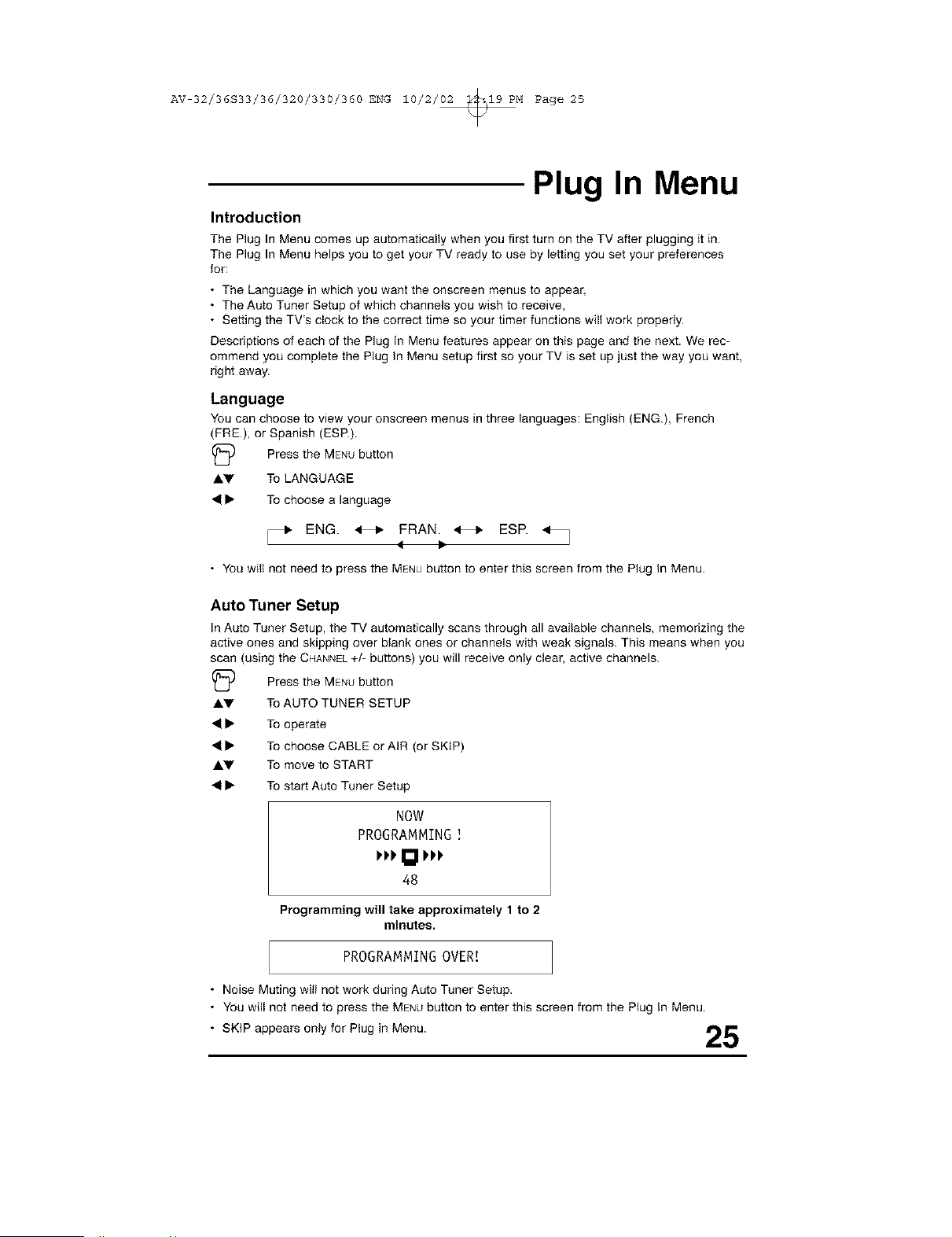
Auto Tuner Setup
In Auto Tuner Setup, the TV automatically scans through all available channels, memorizing the
active ones and skipping over blank ones or channels with weak signals. This means when you
scan (using the CHANNEL+/- buttons) you will receive only clear, active channels.
(_ Press the MENUbutton
AV To AUTO TUNER SETUP
41• To operate
41• To choose CABLE or AIR (or SKIP)
AV To move to START
41• To start Auto Tuner Setup
NOW
PROGRAMMING
I'PPI_l PPP
48
Programming will take approximately 1to 2
minutes.
PROGRAMMINGOVER[
• Noise Muting wiiI not work during Auto Tuner Setup.
• You will not need to press the MENUbutton to enter this screen from the Plug In Menu.
• SKIP appears only for Plug in Menu. _"Ib_'
l,,,q!
AV 32/36S33/36/320/330/360 ENG 10/2/02 _19 PM Page 26
Plug In Menu
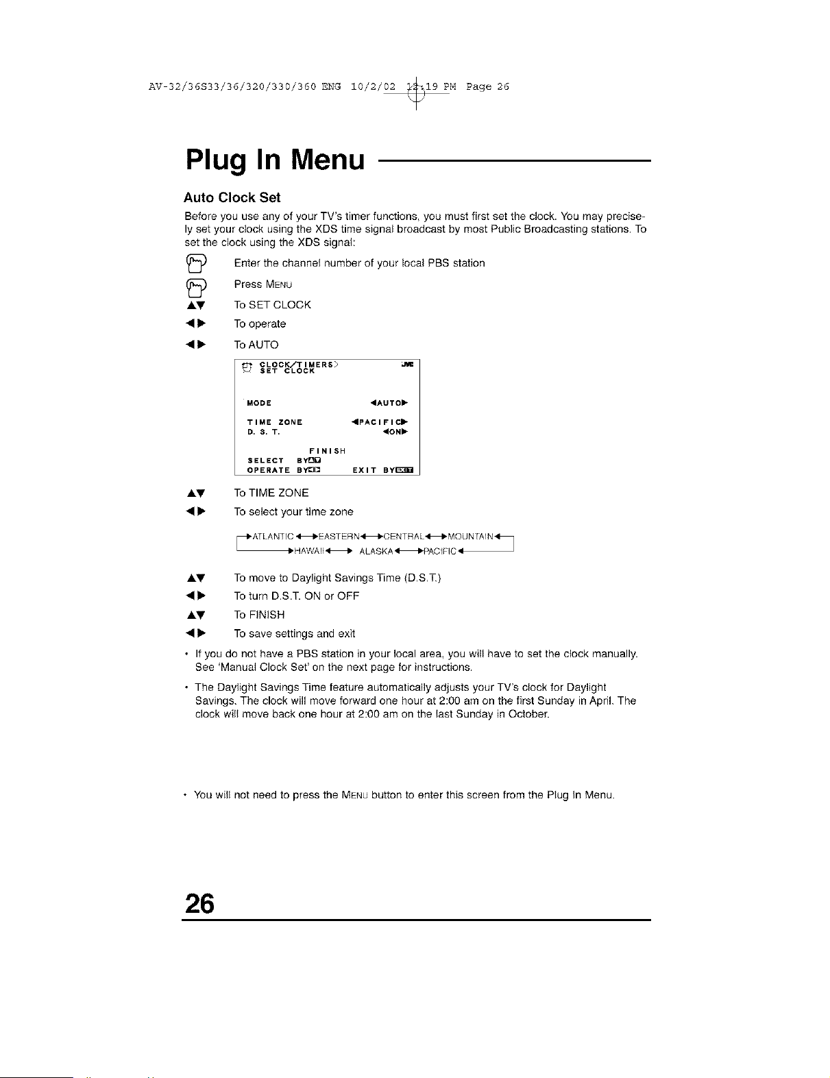
Auto Clock Set
Before you use any of your TV's timer functions, you must first set the dock. You may precise-
ly set your clock using the XDS time signal broadcast by most Public Broadcasting stations. To
set the clock using the XDS signal:
(_ Enter the channel number of local PBS station
your
(_ Press MENU
AI,V To SET CLOCK
• • To operate
• • To AUTO
CLOCK/TIMERS> ,RI
SET CLOCK
MODE 4AUTO"
TIME ZONE "pACIFIC"
D. 8. T. "ON"
FINISH
SELECT BY_
OPERATE By¢3[] EXIT By[_EI
AV To TIME ZONE
• • To select your time zone
1,HAWAII H ALASKA HPACIFIC_
AV To move to Daylight Savings Time (D,S,T.)
• • To turn D.S.T. ON or OFF
AV To FINISH
• • To save settings and exit
• If you do not have a PBS station in your local area, you will have to set the clock manually.
See 'Manual Clock Set' on the next page for instructions.
• The Daylight Savings Time feature automatically adjusts your TV's clock for Daylight
Savings. The clock will move forward one hour at 2:00 am on the first Sunday in April. The
clock will move back one hour at 2:00 am on the last Sunday in October.
• You will not need to press the MENUbutton to enter this screen from the Plug In Menu.
26
AV 32/36S33/36/320/330/360 ENG 10/2/02 _19 PM Page 27
Plug In Menu
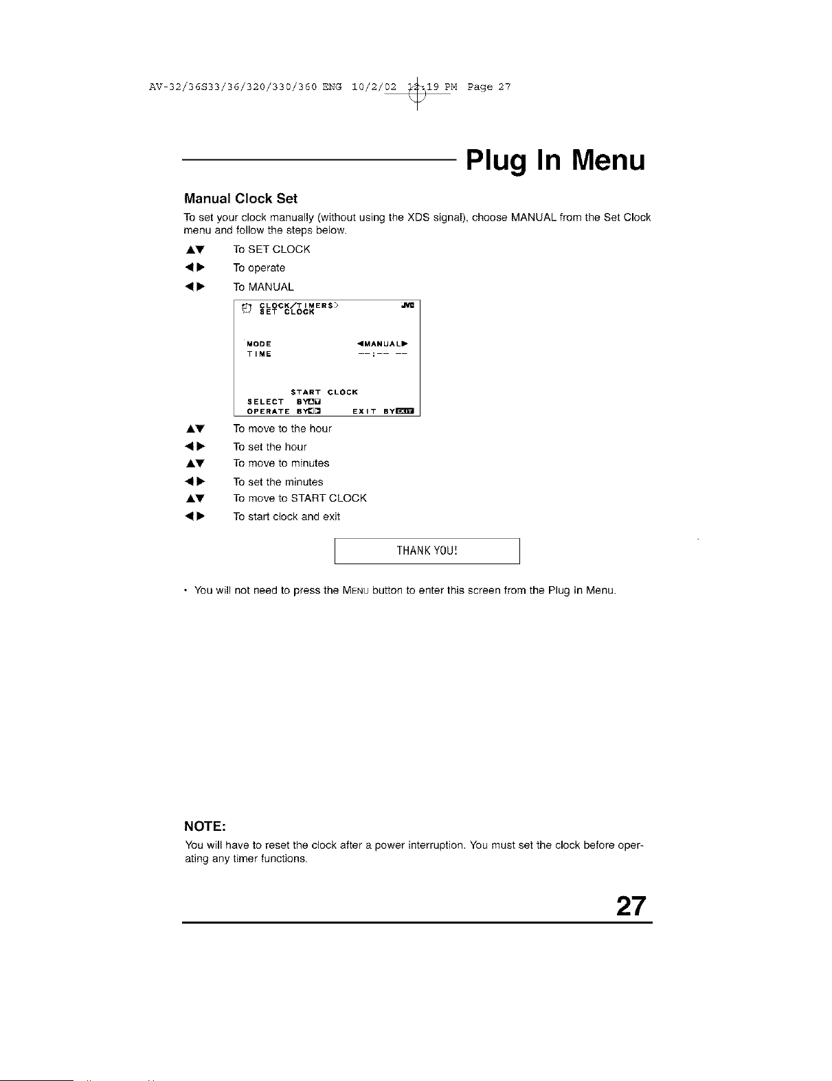
Manual Clock Set
To set your clock manually (without using the XDS signal), choose MANUAL from the Set Clock
menu and follow the steps below.
AV To SET CLOCK
41• To operate
41• To MANUAL
MODE "MANUAL"
TIME
START CLOCK
SELECT BYt_]_
OPERATE BY_[_ EXIT ByE_EI
AV To move to the hour
41• To set the hour
AV To move to minutes
41• To set the minutes
AV To move to START CLOCK
41• To start clock and exit
THANKYOU!
• You will not need to press the MENUbutton to enter this screen from the Plug In Menu.
NOTE:
You will haveto reset the clock after a power interruption, Youmust set the clock before oper-
ating any timer functions.
27
AV 32/36S33/36/320/330/360 ENG 10/2/02 _19 PM Page 28
Channel Summary
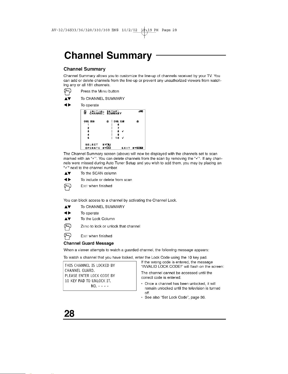
Channel Summary
Channel Summary allows you to customize the line-up of channels received by your TV. You
can add or delete channels from the line-up or prevent any unauthorized viewers from watch-
ing any or all 181 channels.
(_ Press the MENUbutton
AI.y To CHANNEL SUMMARY
41• To operate
INITIAL SETUP>
CHANNEL SUMMARY
CHNO.|C_ Q CHNO.SCAN a
1 8
2 7
8 8 €
4 9
5 10 v'
SELECT BY_
OPERATE BY[][] EXIT By_D_I
The Channel Summary screen (above) will now be displayed with the channels set to scan
marked with an ",/% You can delete channels from the scan by removing the "_'". If any chan-
nels were missed during Auto Tuner Setup and you wish to add them, you may by placing an
,w'. next to the channel number.
Ay To the SCAN column
41• To include or delete from scan
_) EXiT when finished
You
AV
41•
AV
can block access to a channel by activating the Channel Lock.
To CHANNEL SUMMARY
To operate
To the Lock Column
ZEROto lock or unlock that channel
EXITwhen finished
Channel Guard Message
When a viewer attempts to watch aguarded channel, the following message appears:
To watch a channel that you have locked, enter the Lock Code using the 10 key pad.
THIS CHANNELIS LOCKEDBY
CHANNELGUARD.
PLEASEENTERLOCKCODEBY
10 KEYPADTOUNLOCKIT.
NO.----
If the wrong code is entered, the message
"INVALID LOCK CODE!" will flash on the screen:
The channel cannot be accessed until the
correct code is entered.
• Once a channel has been unlocked, it will
remain unlocked until the television is turned
off.
• See also "Set Lock Code", page 36.
28
AV 32/36S33/36/320/330/360 ENG 10/2/02 _19 PM Page 29
V-Chip
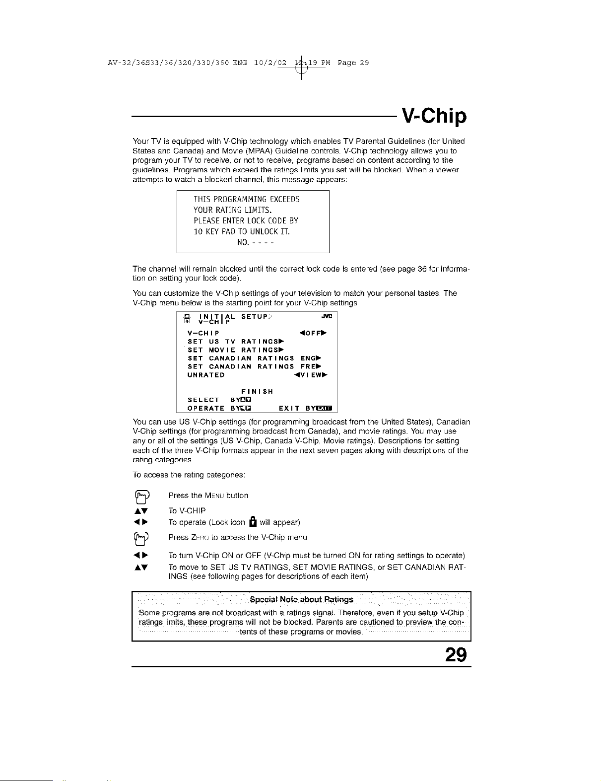
Your TV is equipped with V-Chip technology which enables TV Parental Guidelines (for United
States and Canada) and Movie (MPAA) Guideline controls. V-Chip technology allows you to
program your TV to receive, or not to receive, programs based oi! content according to the
guidelines. Programs which exceed the ratings limits you set will be blocked. When a viewer
attempts to watch a blocked channel, this message appears:
THIS PROGRAMMING EXCEEDS
YOUR RATING LIMITS.
PLEASE ENTERLOCK CODEBY
10 KEYPAD TO UNLOCKIT.
NO.----
The channel will remain blocked until the correct lock code is entered (see page 36 for informa-
tion on setting your lock code).
You can customize the V-Chip settings of your television to match your personal tastes. The
V-Chip menu below is the staring point for your V-Chip settings
INITIAL SETUP> J1/1¢
V--CHIP
V--CHIP 4OFF"
SET US TV RATINGS"
SET MOVIE RATINGS"
SET CANADIAN RATINGS ENG"
SET CANADIAN RATINGS FRE"
UNRATED 4VIEW"
FINISH
SELECT BYDQ
OPERATE BYe[] EXIT BYI_B_I
You can use US V-Chip settings (for programming broadcast from the United States), Canadian
V-Chip settings (for programming broadcast from Canada), and movie ratings. You may use
any or all of the settings (US V-Chip, Canada V-Chip, Movie ratings). Descriptions for setting
each of the three V-Chip formats appear in the next seven pages along with descriptions of the
rating categories.
To access the rating categories:
(_ Press the MENUbutton
Ay To V-CHIP
41• To operate (Lock icon I_ will appear)
(_ Press ZeROto access the V-Chip menu
41• To turn V-Chip ON or OFF (V-Chip must be turned ON for rating settings to operate)
Ay To move to SET US TV RATINGS, SET MOVIE RATINGS, or SET CANADIAN RAT-
INGS (see following pages for descriptions of each item)
I SpeciaI Note about Ratings I
Some programs are not broadcast with a ratings signal. Therefore, even if you setup V-Chip
ratings !imits, these progra ms will not be blocked. Parents are cautioned to preview the con
tents of these programs or moves.
29
AV 32/36S33/36/320/330/360 ENG 10/2/02 _19 PM Page 30
V-Chip
US V-Chip Ratings
U.S. PARENTAL RATING SYSTEMS
Programs with the following ratings are appropriate for children.
TV Y is Appropriate for All Children.
Programs are created for very young viewers and should be suitable for all ages, including
children ages 2 - 6.
TV Y7 is for Older Children.
Most parents would find such programs suitable for children 7 and above. These programs
may contain some mild fantasy violence or comedic violence, which children should be able
to discern from reality.
Programs with the following ratings are designed for the entire audience.
TV G stands for General Audience.
Most parents would find these programs suitable for all age groups. They contain little or no
violence, no strong language, and little or no sexual dialog or situations.
TV PG Parental Guidance Suggested.
May contain some, but not much, strong language, limited violence, and some suggestive
sexual dialog or situations. It is recommended that parents watch these programs first, or
with their children.
TV t4 Parents Strongly Cautioned.
Programs contain some material that may be unsuitable for children under the age of 14
including possible intense violence, sexual situations, strong coarse language, or intensely
suggestive dialog. Parents are cautioned against unattended viewing by children under 14.
TV MA Mature Audiences Only.
These programs are specifically for adults and may be unsuitable for anyone under 17
years of age. TV MA programs may have extensive V, S, L, or D.
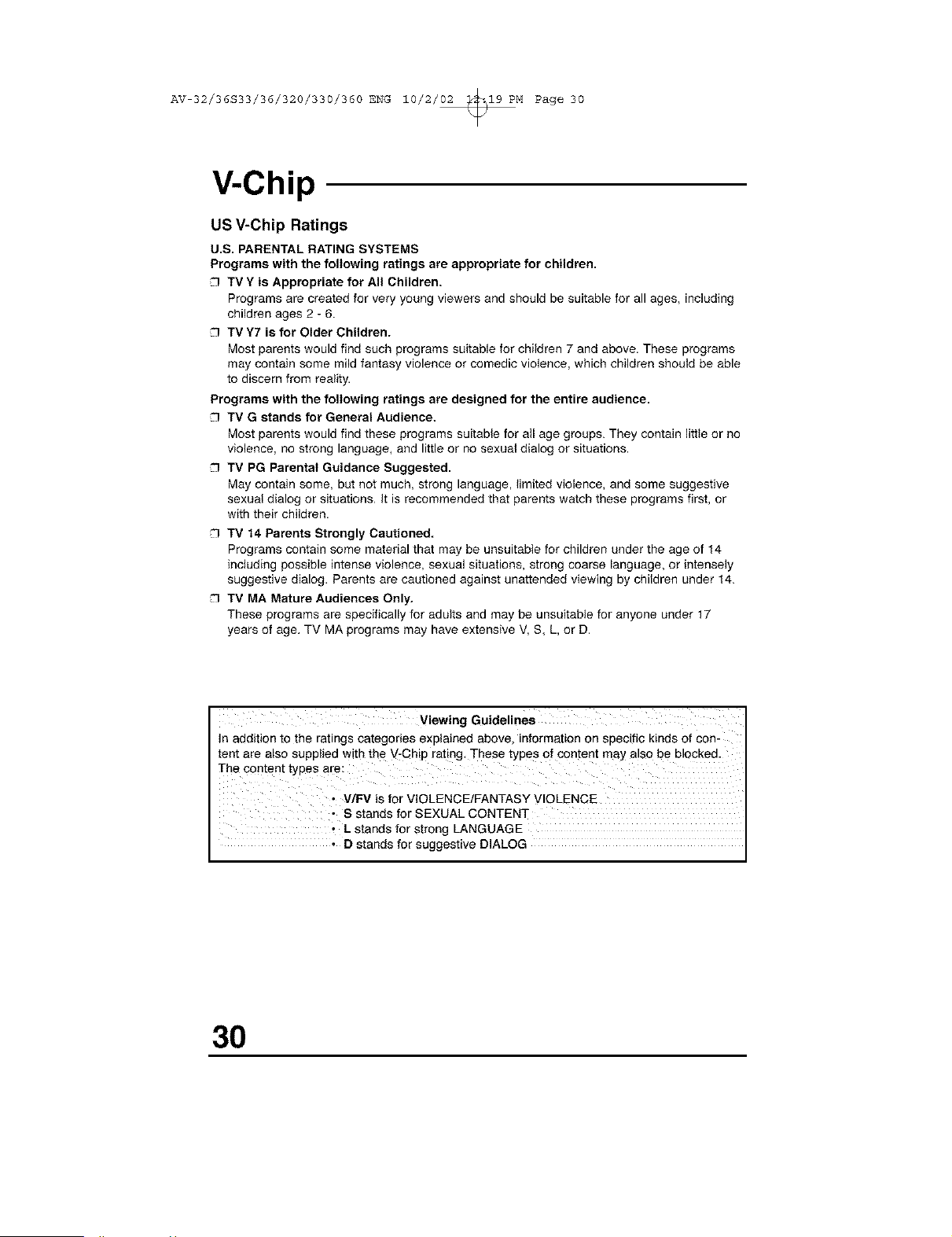
Viewing Guidelines
In addition to the ratings categories explained above, information on specific kinds of con-
tent are also supplied with the V-Chip rating. These types of content may also be blocked.
The content types are:
• V/FV is for VIOLENCE/FANTASY VIOLENCE
• S stands for SEXUAL CONTENT
• Lstands for strong LANGUAGE
• D stands for suggestive DIALOG
30
AV 32/36S33/36/320/330/360 ENG 10/2/02 _19 PM Page 31
Setting US V-Chip Ratings
(_ Press the MENUbutton
AV
V-Chip
To V-CHIP
To operate (Lock icon _ appears)
Press ZERO to access the V-Chip menu
INITIAL SETUP>
V-CHIP
V-CHIP <OFF,
SET US TV RATINGS,
SET MOVIE RATINGS,
SET CANADIAN RATINGS ENG,
SET CANADIAN RATINGS FRE,
UNRATED ,VIEW,
FINISH
SELECT BYD[]
OPERATE BY[]_ EXIT BYl_3gil
• • To turn V-Chip ON or OFF
AV To move to SET US TV RATINGS
• • To operate
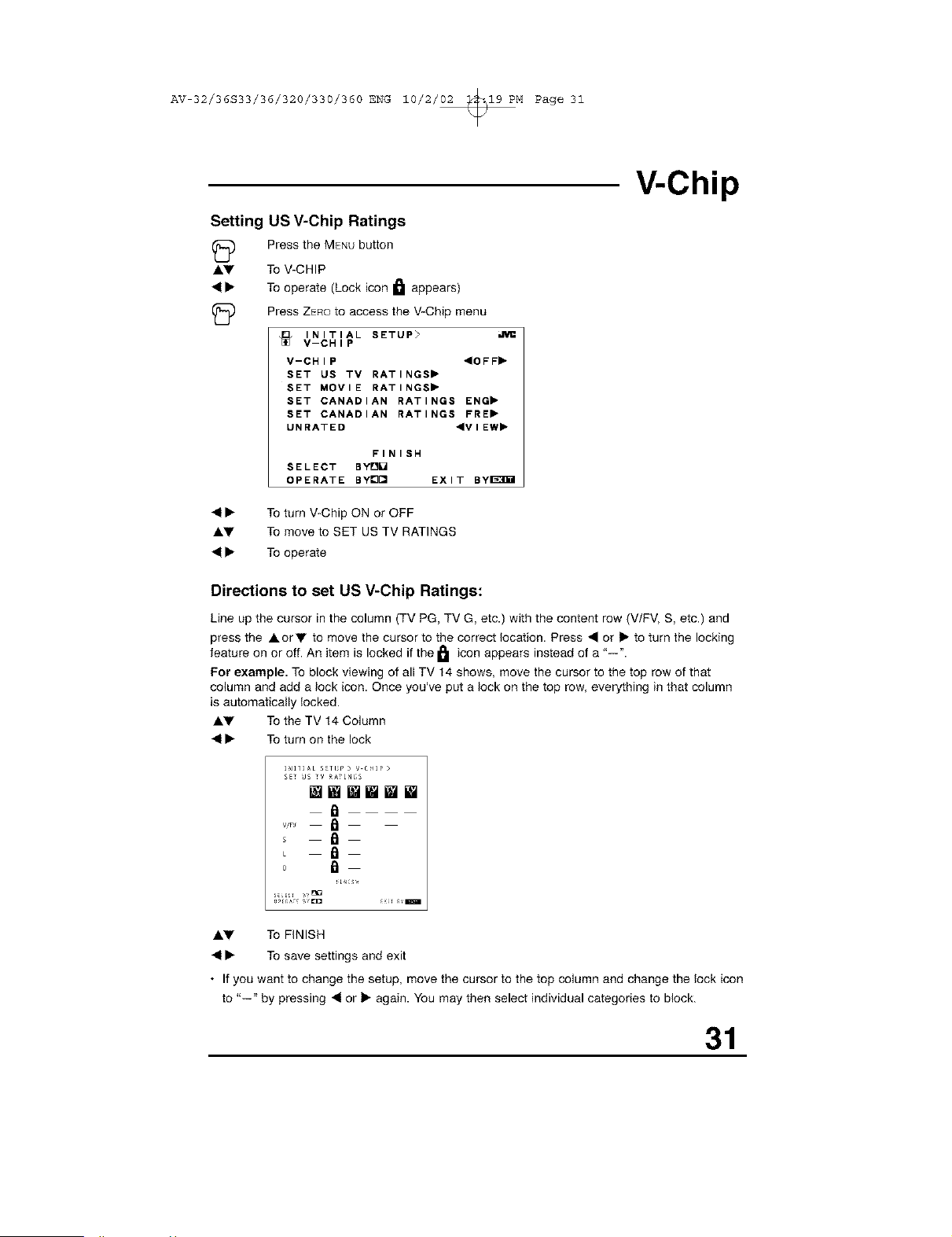
Directions to set US V-Chip Ratings:
Line up the cursor in the column (TV PG, TV G, etc.) with the content row (V/FV, S, etc.) and
press the AorV to move the cursor to the correct location. Press • or • to turn the locking
feature on or off. An item is locked if the I_1 icon appears instead of a "--".
For example. To block viewing of all TV 14 shows, move the cursor to the top row of that
column and add a lock icon. Once you've put a lock on the top row, everything in that column
is automatically locked.
AV To the TV 14 Column
• • To turn on the lock
I_I_]AL S_TL_P > V tRIP>
£ET U£ TV _TI_;S
WWWiWI
a
vPJ
_ a
_ a
o a
iLu_s,,
AV To FINISH
• • To save settings and exit
• If you want to change the setup, move the cursor to the top column and change the lock icon
to "--" by pressing • or • again. You may then select individual categories to block.
31
AV 32/36S33/36/320/330/360 ENG 10/2/02 _19 PM Page 32
V-Chip
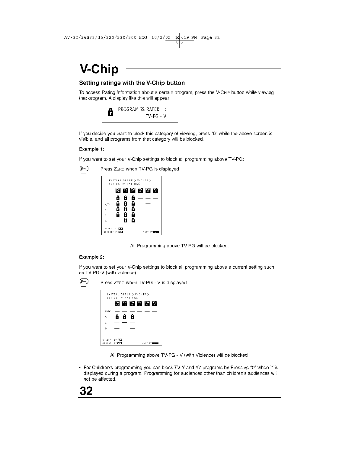
Setting ratings with the V-Chip button
Toaccess Rating information about a certain program, press the V-CHIPbuttonwhile viewing
that program. Adisplay like this will appear:
I_I PROGRAMIS RATED :
TV-PG- V
If you decide you want to block this category of viewing, press "0" while the above screen is
visible, and all programs from that category will be blocked,
Example 1:
If you want to set your V-Chip settings to block all programming above TV-PG:
(_ Press ZEROwhen TV-PG is displayed
INITIAL SE_ UP > V C_{_? >
SE_ US _V RA]INGS
wwmmww
_aa
, _aa
_aa
° a a
All Programming above TV-PG will be blocked.
Example 2:
If you want to set your V-Chip settings to block all programming above a current setting such
as TV PG-V (with violence):
(_ Press ZEROwhen TV-PG - V is displayed
!_ir_t*L S£_U? > V C_{17 >
S£_ JS _V RA]I_IGS
mwmwwE
V,,FV
All Programming above TV-PG - V (with Violence) will be blocked,
• For Children's programming you can block TV-Y and Y7 programs by Pressing "0" when Y is
displayed during a program. Programming for audiences other than children's audiences will
not be affected.
32
AV 32/36S33/36/320/330/360 ENG 10/2/02 _19 PM Page 33
V-Chip
Movie Ratings
NR - Not Rated.
This is a film which has no rating, in many cases these films were imported from countries
which do not use the MPAA ratings system. Other NR films may be from amateur producers
who didn't intend to have their film widely released.
NR (Not Rated) Programming may contain all types of programming including chil-
dren's programming, foreign programs, or adult material.
G - General Audience.
In the opinion of the review board, these films contain nothing in the way of sexual content
violence, or language that would be unsuitable for audiences of any age.
PG - Parental Guidance.
Parental Guidance means the movie may contain some contents such as mild violence,
some brief nudity_ and strong language. The contents are not deemed intense.
PG*13 - Parents Strongly Cautioned.
Parents with children under 13 are cautioned that the content of movies with this rating may
include more explicit sexual, language, and violence content than movies rated PG.
R - Restricted.
These films contain material that is explicit in nature and is not recommended for
unsupervised children under the age of 17.
NC-17 * No One Under 17.
These movies contain content which most parents would feel is too adult for their children to
view. Content can consist of strong language, nudity, violence, and suggestive or explicit
subject matter.
X - No One under 18.
Inappropriate material for anyone under 18.
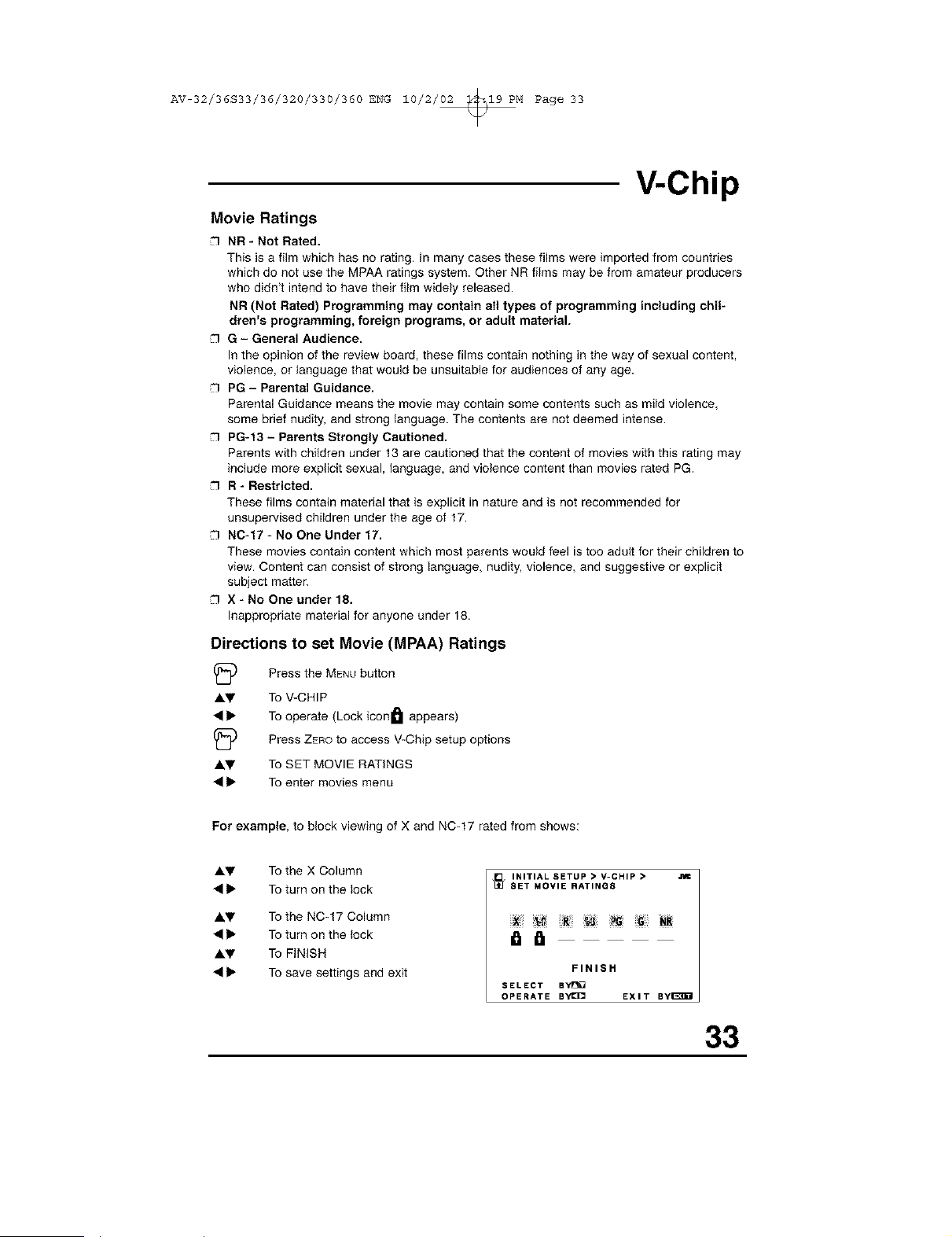
Directions to set Movie (MPAA) Ratings
I_) Press the MENUbutton
A.V To V-CHIP
• • To operate (Lock iconl_ I appears)
I_ to access V-Chip setup options
Press ZERO
_.y To SET MOVIE RATINGS
• • To enter movies menu
For example, to block viewing of X and NC-17 rated from shows:
A.V To the X Column
• • To turn on the lock
AI,y To the NC-t 7 Column
• • To turn on the lock
Ay To FINISH
• • To save settings and exit
INITIAL SETUP • V-CHIP • Jim
_SET MOVIE RATING8
FINIS H
SELECT BYe[]
OPERATE ByI_]C= EXIT Byi_B_I
33
AV 32/36S33/36/320/330/360 ENG 10/2/02 _19 PM Page 34
V-Chip
Canadian V-Chip Ratings
E - Exempt.
Exempt programming includes: news, sports, documentaries and other information
programming, talk shows, music videos, and variety programming.
C - Programming Intended for Children.
Violence Guidelines: There will be no realistic scenes of violence. Depictions of aggressive
behavior will be infrequent and limited to portrayals that are clearly imaginary, comedic or
unrealistic in nature.
C8+ - Programming Intended for Children 8 and Over.
Violence Guidelines: Any realistic depictions of violence will be infrequent, discreet, of low
intensity and will show the consequences of the acts. There will be no offensive language,
nudity or sexual content.
G - General Audience.
Programming will contain little violence and will be sensitive to themes which could affect
younger children.
PG - Parental Guidance.
Programming intended for a general audience, but which may not be suitable for younger
children. Parents may consider some content not appropriate for children aged 8-13.
14+ - 14 Years and Older.
Parents are strongly cautioned to exercise discretion in permitting viewing by pre-teens and
early teens. Programming may contain mature themes and scenes of intense violence.
18+ - Adult.
Material intended for mature audiences only.
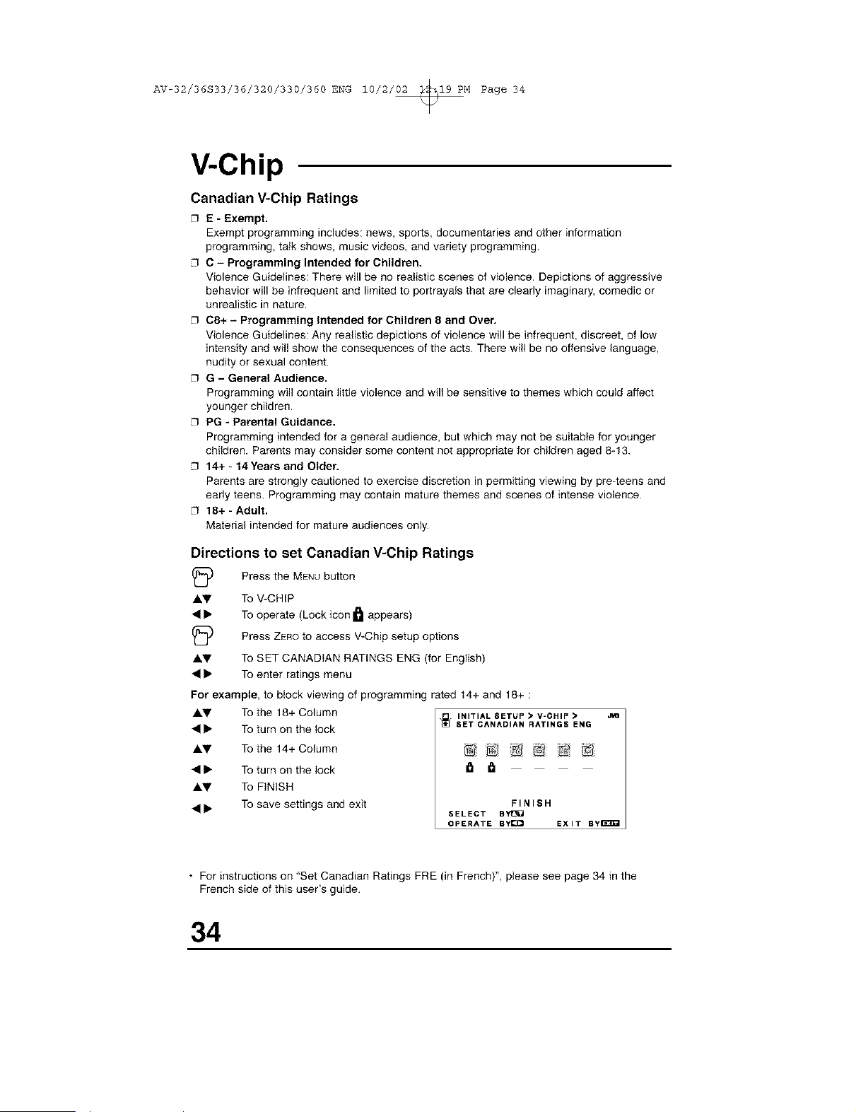
Directions to set Canadian V-Chip Ratings
(_) Press the MENUbutton
A'!r To V-CHIP
• • To operate (Lock icon _]l appears)
(_ Press ZEno to access V-Chip setup options
Ay To SET CANADIAN RATINGS ENG (for English)
• • To enter ratings menu
For example, to block viewing of programming rated 14+ and 18+ :
&V To the 18+ Column
• • To turn on the lock
&V To the 14+ Column
• • To turn on the lock
&_' To FINISH
• • To save settings and exit
INITIAL 6ETUP • V-CHIP •
SET CANADIAN RATINGS ENG
@ @ @
FINIS H
SELECT BYtJU
OPERATE BYI_ EXIT ByE_I
• For instructions on "Set Canadian Ratings FRE (in French)", please see page 34 in the
French side of this user's guide.
34
AV 32/36S33/36/320/330/360 ENG 10/2/02 _19 PM Page 35
V-Chip
Unrated Programs
Notes About Unrated Programs
Unratedprogrammingrefers to any programming whichdoes not contain a rating signal
Programming on television stations which do not broadcast rating signals will be placed in the
"Unrated Programming" category.
Examples of Unrated programs:
Emergency Bulletins
Locally Originated Programming
News
Political Programs
Public Service Announcements
Religious Programs
Sports
Weather
Some Commercials
• TV programs or movies that do not have rating signals will be blocked if the Unrated
Category is set to BLOCK.
Directions to Block Unrated Programs
Youcan block programs that are not rated.
A'Y
A'Y
Press the MENUbutton
To V-CHIP
To operate (The lock icon I_1 appears)
I
Press ZEROto access V-Chip setup options
To UNRATED
To VIEW or BLOCK
Press EXITwhen done
35
AV 32/36S33/36/320/330/360 ENG 10/2/02 _19 PM Page 36
V-Chip
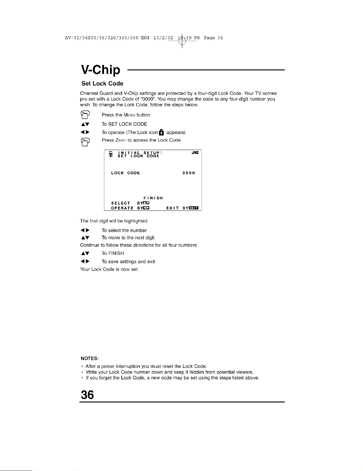
Set Lock Code
Channel Guard and V-Chip settings are protected by a four-digit Lock Code. Your TV comes
pre-set with a Lock Code of "0000". You may change the code to any four-digit number you
wish. To change the Lock Code, follow the steps below.
(_ Press the MENUbutton
AV To SET LOCK CODE
41• To operate (The Lock icon I_1 appears)
(_ Press ZEROto access the Lock Code
]_ INITIAL SETUP>
SET LOCK CODE
LOCK CODE 0000
FINISH
SELECT BYOO
OPERATE BY_Q EXIT BYI_I
The first digit will be highlighted
41• To select the number
AV To move to the next digit
Continue to follow these directions for all four numbers
AV To FINISH
41• To save settings and exit
Your Lock Code is now set.
NOTES:
• After a power interruption you must reset the Lock Code.
• Write your Lock Code number down and keep it hidden from potential viewers.
• If you forget the Lock Code, a new code may be set using the steps listed above.
36
AV 32/36S33/36/320/330/360 ENG 10/2/02 _19 PM Page 37
Picture Settings
Tint
Tint allows you to adjust the levels of red and green in your TV picture,
1_ Press the MENUbutton
AV To TINT
I_ To increase the levels of green
• To increase the levels of red
AV To move to the next setting
Color
The color function lets you make all the colors in the TV picture appear either more vivid or
subtle.
(_ Press the MENUbutton
AV To COLOR
I_ To make the colors more vivid
• To make the colors more subdued
AV To move to the next setting
Picture
Picture allows you to adjust the levels of black and white on the TV screen, giving you a darker
or brighter picture overall.
Press the MENUbutton
AV To PICTURE
I_ To increase the level of contrast
• To decrease the level of contrast
AV To move to the next setting
Bright
You can adjust the overall brightness of the TV picture with the Bright control,
(_ Press the MENUbutton
AV To BRIGHT
I_ To lighten the picture
• To darken the picture
AV To move to the next setting
Detail
The Detail feature adjusts the level of fine detail displayed in the picture.
(_ Press the MENUbutton
AV To DETAIL
I_ To make the picture sharper (more detail)
• To make the picture smoother (less detail)
AV To move to the next setting
37
AV 32/36S33/36/320/330/360 ENG 10/2/02 _19 PM Page 38
Picture Settings
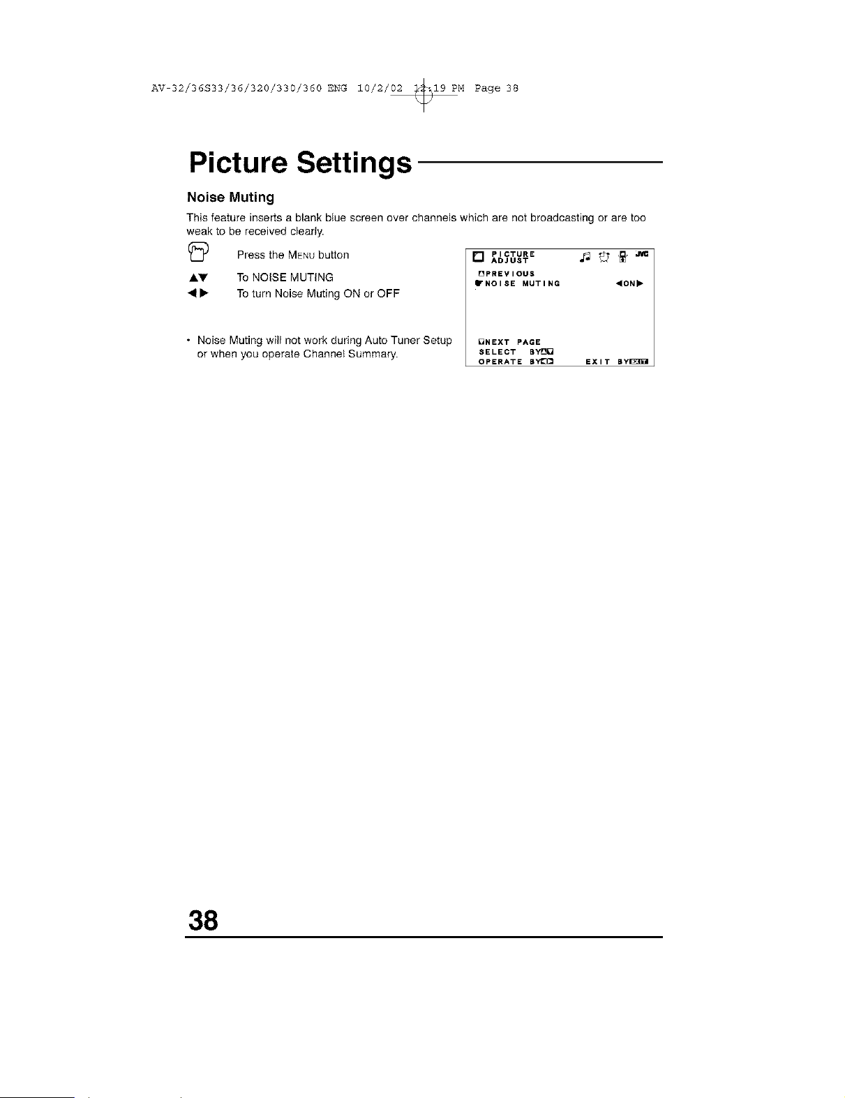
Noise Muting
This feature inserts a blank blue screen over channels which are not broadcasting or are too
weak to be received clearly.
I_ Press the MENUbutton
AV To NOISE MUTING
41• To turn Noise Muting ON or OFF
• Noise Muting will not work during Auto Tuner Setup
or when you operate Channel Summary.
[] PICTURE _ _ _"
ADJUST
[]PREVIOUS
"NOISE MUTING "ON"
DNEXT PAGE
SELECT BYD[]
OPERATE BYI_ EXIT BYI_B_I
38
AV 32/36S33/36/320/330/360 ENG 10/2/02 _19 PM Page 39
Sound Settings
Bass
You can increase or decrease the level of low-frequency sound in the TV's audio with the Bass
adjustment.
AV
41
AV
Treble
Use Treble to adjust the level of high-frequency sound in your TV's audio.
I_ Press the MENUbutton
AV To TREBLE
• To increase the treble
41 To decrease the treble
AV To move to the next setting
Balance
Adjust the level of sound between the TV's two speakers with the Balance setting.
Press the MENUbutton
TOBASS
TOincrease the bass
To decrease the bass
To move to the next setting
(_ Press the MENUbutton
AV To BALANCE
• To shift the balance towards the right speaker
41 To shift the balance towards the left speaker
AV To move to the next setting
MTS (Multi-Channel Television Sound)
MTS technology allows several audio signals to be broadcast at once, giving you a choice in
what you wish to hear with a TV program. In addition to mono or stereo sound, an MTS broad-
cast may also include a Second Audio Program (SAP),
I_ Press the MENUbutton
AV To MTS
41• Select the mode
(The ON AIR arrow tells you if a broadcast is in Stereo and/or contains an SAP).
• Keep the TV in STEREO mode to get the best sound quality. The sound will work in
STEREO mode even if a certain broadcast is in MONO sound only.
• Choose the MONO setting to reduce excessive noise on a certain channel or broadcast.
• Selecting SAP will allow you to hear an alternative soundtrack, if one is available.
NOTE:
You can leave the Sound Settings menu at any time by pressing the EXITbutton on the remote
control,
39
AV 32/36S33/36/320/330/360 ENG 10/2/02 _19 PM Page 40
General Items
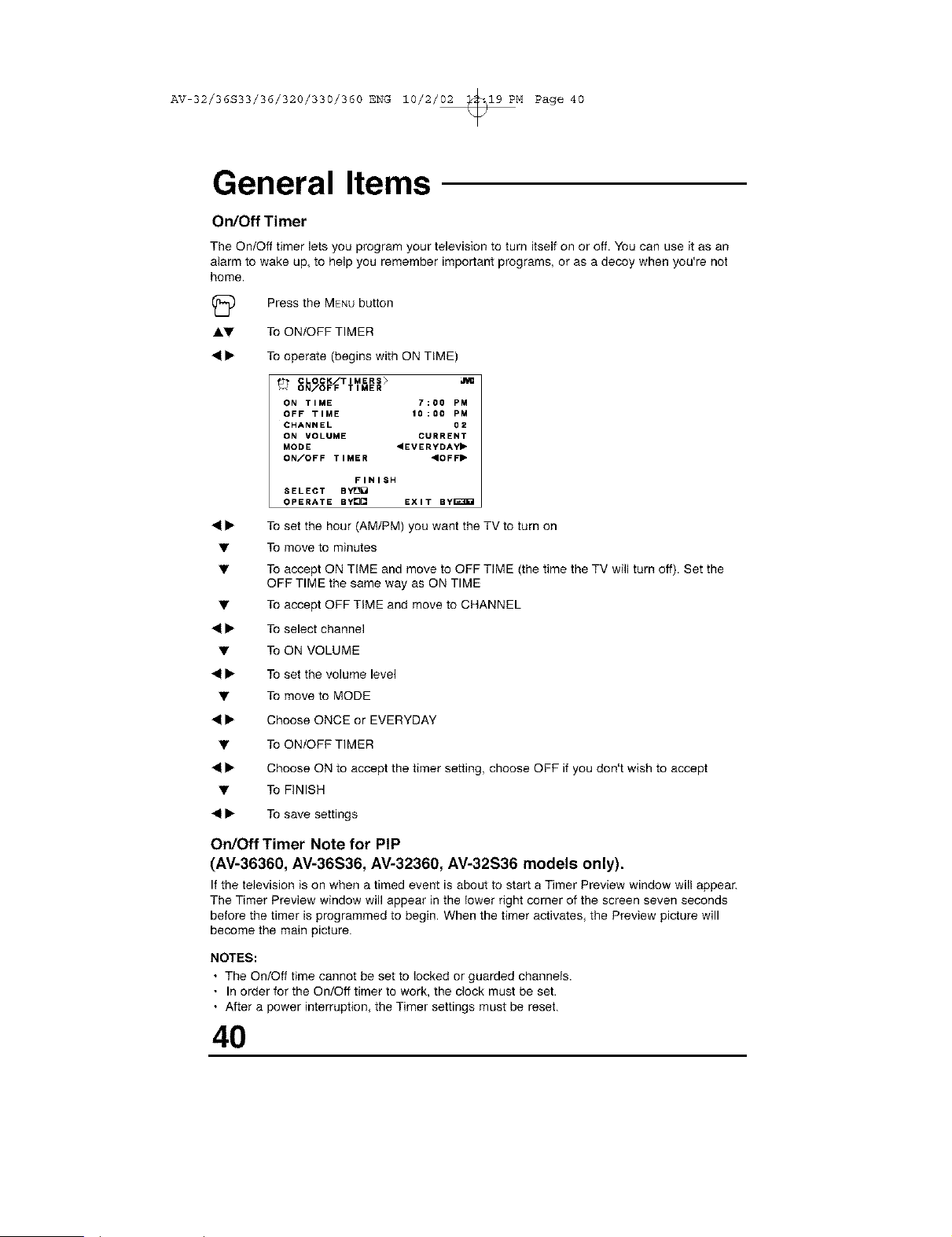
On/Off Timer
The On/Off timer lets you program your television to turn itself on or off. You can use it as an
alarm to wake up, to help you remember important programs, or as a decoy when you're not
home.
(_ Press the MENUbutton
Ay To ON/OFF TIMER
41• To operate (begins with ON TIME)
CLOCK/TIMERS>
ON/OFF TIMER
ON TIME 7;00 PM
OFF TIME 10:00 PM
CHANNEL 02
ON VOLUME CURRENT
MODE <EVERYDAY"
ON/OFF TIMER "OFF"
FINISH
SELECT BYIO_
OPERATE BYe[] EXIT By_3B_
41• To set the hour (AM/PM) you want the TV to turn on
• To move to minutes
• To accept ON TIME and move to OFF TIME (the time the TV will turn off). Set the
OFF TIME the same way as ON TIME
• To accept OFF TIME and move to CHANNEL
41• To select channel
• To ON VOLUME
41• To set the volume level
• To move to MODE
41• Choose ONCE or EVERYDAY
• To ON/OFF TIMER
41• Choose ON to accept the timer setting, choose OFF if you don't wish to accept
• To FINISH
41• To save settings
On/Off Timer Note for PIP
(AV-36360, AV-36S36, AV-32360, AV-32S36 models only).
If the television is on when a timed event is about to start a Timer Preview window will appear.
The Timer Preview window will appear in the lower right corner of the screen seven seconds
before the timer is programmed to begin. When the timer activates, the Preview picture will
become the main picture.
NOTES:
• The On/Off time cannot be set to locked or guarded channels.
• In order for the On/Off timer to work, the clock must be set.
• After a power interruption, the Timer settings must be reset.
40
AV 32/36S33/36/320/330/360 ENG 10/2/02 _19 PM Page 41
General Items
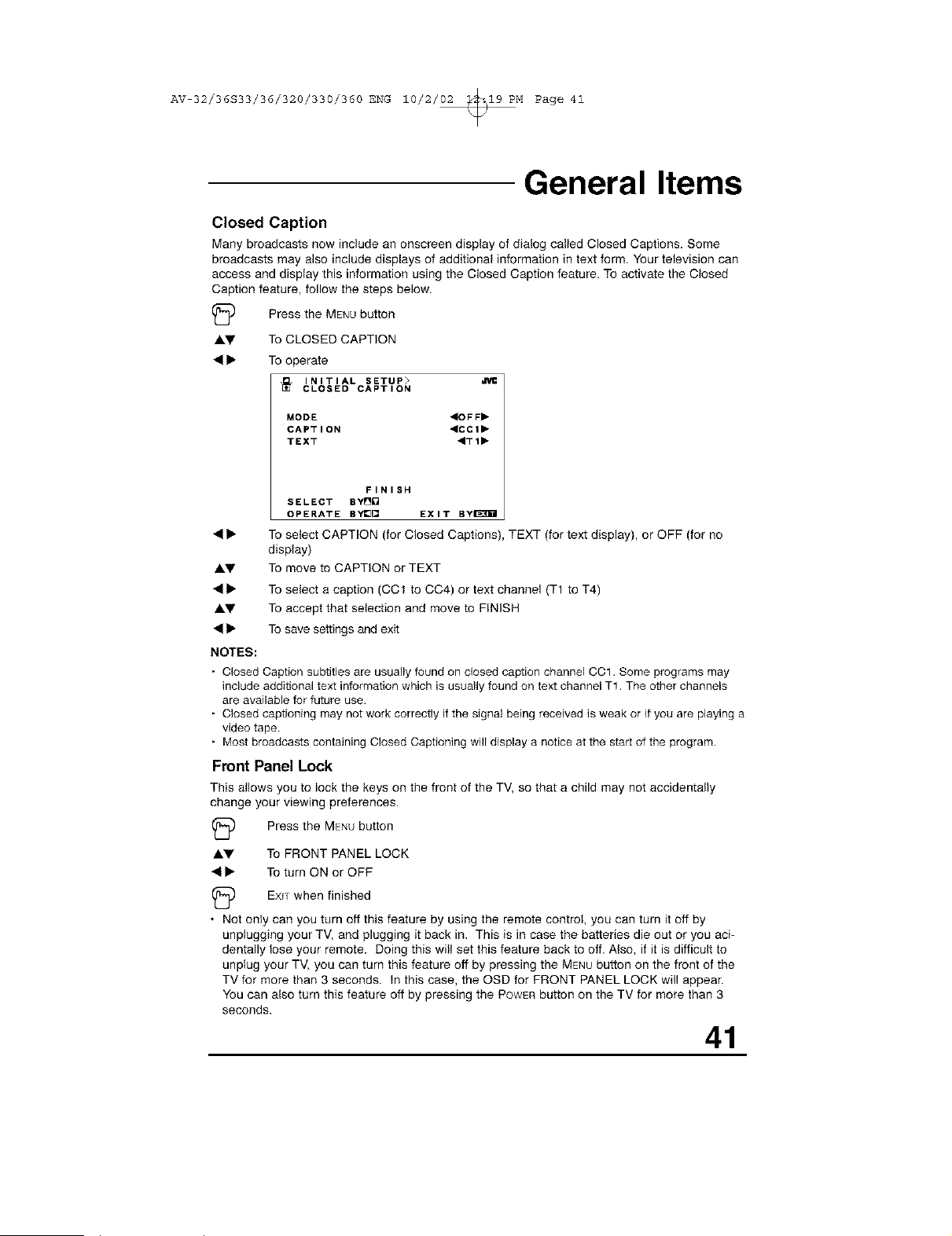
Closed Caption
Many broadcasts now include an onscreen display of dialog called Closed Captions. Some
broadcasts may also include displays of additional information in text form. Your television can
access and display this information using the Closed Caption feature. To activate the Closed
Caption feature, follow the steps below.
(_5) Press the MENUbutton
AI,V To CLOSED CAPTION
• • To operate
INITIAL SETUP>
CLOSED CAPTION
MODE "OFF"
CAPTION "CCI"
TEXT ,TI_
FINISH
SELECT BY[]O
OPERATE BYI_ EXIT BY_H
AT
To select CAPTION (for Closed Captions), TEXT (for text display), or OFF (for no
display)
To move to CAPTION or TEXT
AT
To select a caption (CCt to CC4) or text channel (T1 to T4)
To accept that selection and move to FINISH
To save settings and exit
NOTES:
Closed Caption subtitles are usually found on closed caption channel CC1. Some programs may
include additional text information which is usually found on text channel T1 The other channels
are available for future use.
Closed captioning may not work correctly if the signal being received is weak or it you are playing a
video tape.
Most broadcasts containing Closed Captioning will display a notice at the start of the program.
Front Panel Lock
This atlows you to lock the keys on the front of the TV, so that a child may not accidentally
change your viewing preferences.
(_ Press the MENUbutton
Ay To FRONT PANEL LOCK
• • To turn ON or OFF
(_ EXITwhen finished
• Not only can you turn off this feature by using the remote control, you can turn it off by
unplugging your TV, and plugging it back in. This is in case the batteries die out or you aci-
dentally lose your remote. Doing this will set this feature back to off. Also, if it is difficult to
unplug your TV, you can turn this feature off by pressing the MENUbutton on the front of the
TV for more than 3 seconds. In this case, the OSD for FRONT PANEL LOCK will appear.
You can also turn this feature off by pressing the POWERbutton on the TV for more than 3
seconds.
41
AV 32/36S33/36/320/330/360 ENG 10/2/02 _19 PM Page 42
General Items
Auto Shut Off
This function automatically shuts off your TV when there is no signal from the channel the TV
is on.
(_D Press the MENUbutton
A.V To AUTO SHUT OFF
_11_ To turn ON or OFF
(_ EXITwhen finished
• If the channel that you have on does not recieve a signal for more than one minute, the
blinking text "NOT REClEVING A SlGNAU' appears on the screen. If no signal is being
recieved within 10 minutes, the TV shuts itself off.
XDS ID
XDS ID Display provides a channels call letters, the network's name, and even a program
name.
(_ Press the MENUbutton
A.V To XDS ID
_11_ To turn ON or OFF
(_ EXITwhen finished
• XDS ID is available on all models except for AV-36320 and AV-32320.
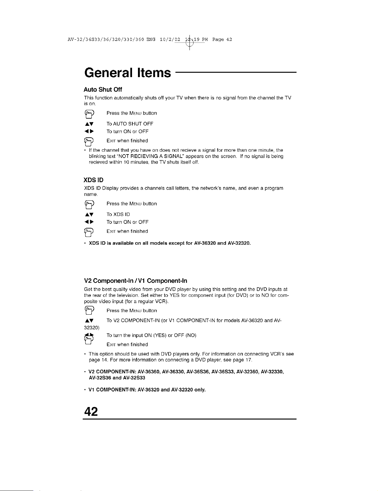
V2 Component-In IV1 Component-In
Get the best quality video from your DVD player by using this setting and the DVD inputs at
the rear of the television. Set either to YES for component input (for DVD) or to NO for com-
posite video input (for a regular VCR).
(_) Press the MENUbutton
AV To V2 COMPONENT-IN (or Vt COMPONENT-IN for models AV-36320 and AV-
32320)
To turn the input ON (YES) or OFF (NO)
EXITwhen finished
• This option should be used with DVD players only. For information on connecting VCR's see
page 14, For more information on connecting a DVD player, see page 17.
• V2 COMPONENT*IN: AV-36360, AV-36330, AV-36S36, AV-36S33, AV-32360, AV-32330,
AV-32S36 and AV-32S33
• Vl COMPONENT*IN: AV-36320 and AV-32320 only.
42
AV 32/36S33/36/320/330/360 ENG 10/2/02 _19 PM Page 43
Button Functions
Menu
The MENUbutton allOWSyou to access JVC's onscreen menu system. Press MENUto activate
the onscreen menu system.
• See individual topics (like "Sound Settings) for specific information on using menus.
Exit and PiP Off
Press the EXITbutton to leave a menu screen. On the RM-C254 this button is also labeled 'PIP
OFF". Press ExIT/PIP OFF 10turn off the Picture-in-Picture function (please see page 47 for
more information on the PIP feature).
• PIP is available on AV-36360, AV-36S36, AV-32360 and AV-32S36 models only.
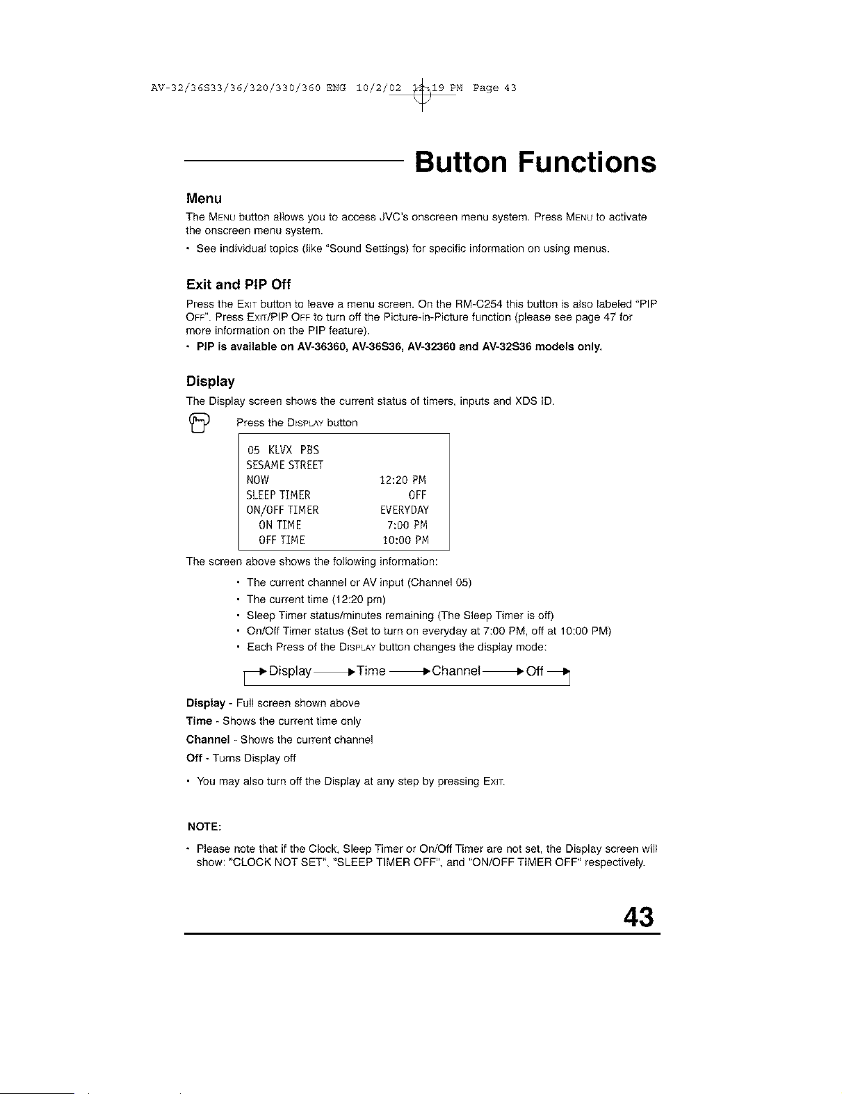
Display
The Display screen shows the current status of timers, inputs and XDS ID.
(_ Press the DISPLAYbutton
05 KLVX PBS
SESAMESTREET
NOW 12:20 PM
SLEEPTIMER OFF
ON/OFF TIMER EVERYDAY
ON TIME 7:00 PM
OFFTIME 10:00 PM
The screen above shows the following information:
The current channel or AV input (Channel 05)
The current time (12:20 pm)
Sleep Timer status/minutes remaining (The Steep Timer is off)
On/Off Timer status (Set to turn on everyday at 7:00 PM, off at 10:00 PM)
Each Press of the DISPLAYbutton changes the display mode:
Display _ Time _ Channel _ Off
Display - Full screen shown above
Time - Shows the current time only
Channel - Shows the current channel
Off - Turns Display off
• You may also turn off the Display at any step by pressing EXIT.
NOTE:
• Please note that if the Clock, Sleep Timer or On/Off Timer are not set, the Display screen will
show: "CLOCK NOT SET", "SLEEP TIMER OFF", and "ON/OFF TIMER OFF" respectively.
43
AV 32/36S33/36/320/330/360 ENG 10/2/02 _19 PM Page 44
Button Functions
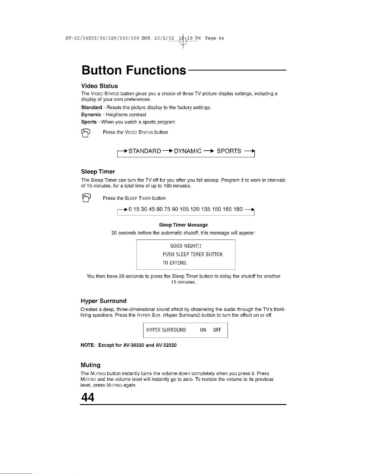
Video Status
The V_DEOSTATUSbutton gives you a choice of three TV picture display settings, including a
display of your own preferences.
Standard - Resets the picture display to the factory settings,
Dynamic - Heightens contrast
Sports - When you watch a sports program
(_ Press the WDEOSTATUSbutton
_.STANDARD-_ DYNAMIC-_ SPORTS _j
Sleep Timer
The Sleep Timer can turn the TV off for you after you fall asleep. Program it to work in intervals
of 15 minutes, for a total time of up to 180 minutes.
(_ Press the SLEEPTIMERbutton
_IP0 15 30 45 60 75 90 105 120 135 150 165 180
Sleep Timer Message
20 seconds before the automatic shutoff, this message will appear:
GOOD NIGHT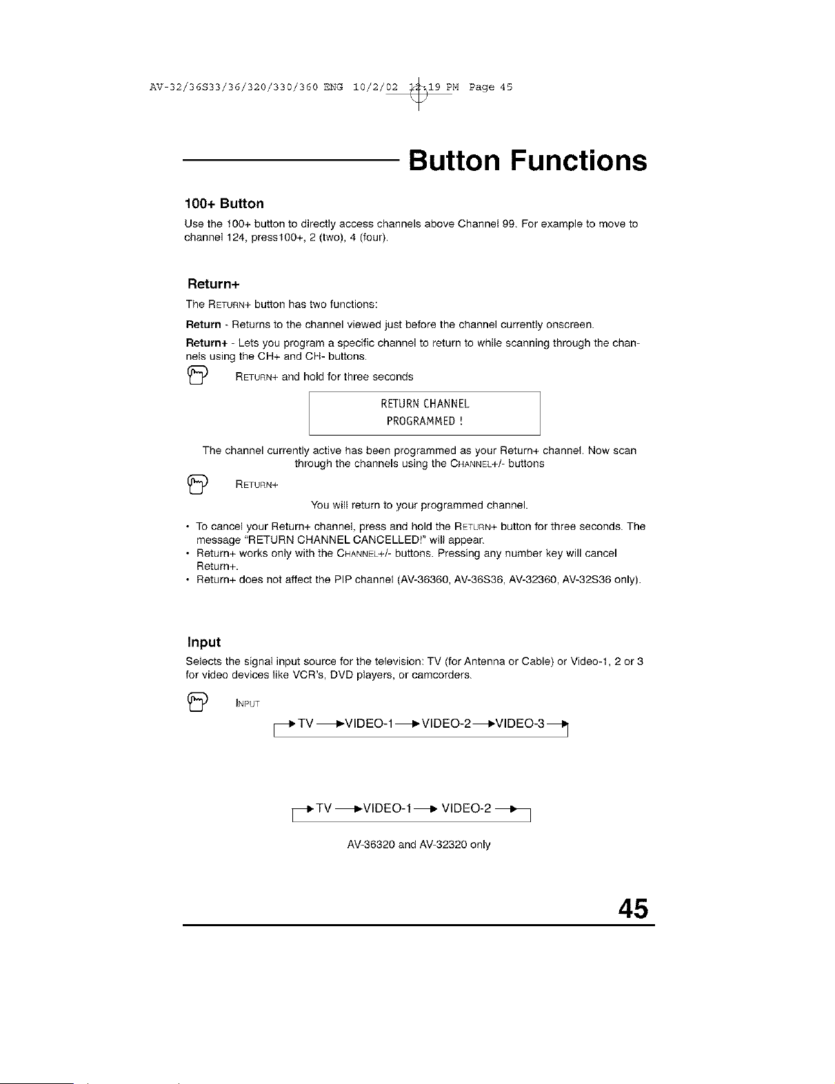
AV 32/36S33/36/320/330/360 ENG 10/2/02 _19 PM Page 45
Button Functions
100+ Button
Use the 100+ button to directly access channels above Channel 99. For example to moveto
channel 124, presst 00+, 2 (two), 4 (four).
Return+
The RETURN+button has two functions:
Return - Returns to the channel viewed just before the channel currently onscreen.
Return+ - Lets you program a specific channel to return to while scanning through the chan-
nels using the CH+ and CH- buttons.
(_ RETURN+and hold for three seconds
RETURN CHANNEL
PROGRAMMED!
The channel currently active has been programmed as your Return+ channel Now scan
through the channels using the CHANNEL+/-buttons
(_D RETURN+
You will return to your programmed channel.
• To cancel your Return+ channel, press and hold the RETURN+button for three seconds. The
message "RETURN CHANNEL CANCELLED!" will appear.
• Return+ works only with the CHANNEL+/-buttons. Pressing any number key will cancel
Return+.
• Return+ does not affect the PIP channel (AV-36360, AV-36S36, AV-32360, AV-32S36 only).
Input
Selects the signal input source for the television: TV (for Antenna or Cable) or Video-t, 2 or 3
for video devices like VCR's, DVD players, or camcorders.
(_D INPUT
_.TV _VIDEO-1 _ VlDEO-2_VIDEO-3 _
_TV _VIDEO-I_ VIDEO-2 _]
AV-36320and AV-32320only
45
AV 32/36S33/36/320/330/360 ENG 10/2/02 _19 PM Page 46
Button Functions
VCR Buttons
You can use this remote control to operate the basic functions of your VCR. These functions
include: play, record, rewind, fast-forward, stop, pause, channel scan, TV/VCR, power on, and
power off.
Move the selector switch to VCR to operate.
• The remote is preset with the code 000 to control JVC-brand VCR's. For any other manufac-
turer's brand VGR, please see the code chart and instructions on page 21.
NOTE: The RM-C205 remote control can only be used with JVC-brand VGRs.
DVD Buttons (RM-C254, RM-C255 only)
You can also use this remote control to operate the basic functions of your DVD player. These
functions include: play, rewind, fast-forward, stop, still/pause, previous/next tray open/close,
power on, and power off.
Move the selector switch to DVD to operate.
• The remote is preset with the code 000 to control JVC-brand DVD players. For any other
manufacturer's brand DVD player, please see the code chart and instructions on page 22.
TV/CATV Switch (RM-C254, RM-C255 only)
Use either the television's own tuner or a cable box to select channels. Set this switch to TV to
operate the television's built-in tuner. Move the switch to GATV to operate a cable box,
• See page 20 for information on programming your remote for cable box operation.
VCR/DVD Switch (RM-C254, RM-C255 only)
You can control a VCR or DVD player with the buttons on the lower part of the remote control.
Use the VCR/DVD selector switch to choose either VCR or DVD operation.
• See pages 21 and 22 for information on programming your remote with VCR and DVD oper-
ating codes.
46
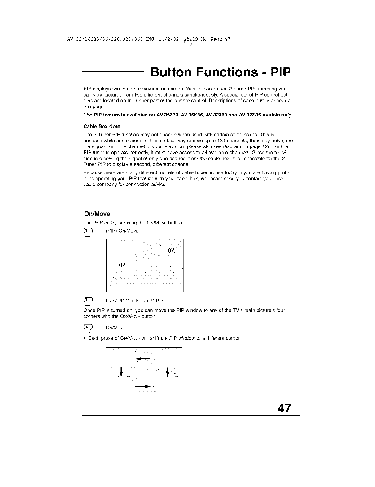
AV 32/36S33/36/320/330/360 ENG 10/2/02 _19 PM Page 47
Button Functions- PIP
PIP displays two separate pictures on screen. Your television has 2-Tuner PIP, meaning you
can view pictures from two different channels simultaneously. A special set of PIP control but-
tons are located on the upper part of the remote control Descriptions of each button appear on
this page.
The PiP feature is available on AV-36360, AV-36S36, AV-32360 and AV-32S36 models only.
Cable Box Note
The 2-Tuner PIP function may not operate when used with certain cable boxes. This is
because while some models of cable box may receive up to 181 channels, they may only send
the signal from one channel to your television (please also see diagram on page 12). For the
PIP tuner to operate correctly, it must have access to all available channels. Since the televi-
sion is receiving the signal of only one channel from the cable box, it is impossible for the 2-
Tuner PIP to display a second, different channel
Because there are many different models of cable boxes in use today, if you are having prob-
lems operating your PIP feature with your cable box, we recommend you contact your local
cable company for connection advice,
On/Move
Turn PIP on by pressing the ON/MOVE button.
(_ (PIP) ON/MOVE
(_ EmT/PtP OFF to turn PIP off
Once PtP is turned on, you can move the PIP window to any of the TV's main picture's four
corners with the ON/MOVEbutton.
(_ ON/MOVE
• Each press of ON/MOVEwill shift the PIP window to a different corner,
47
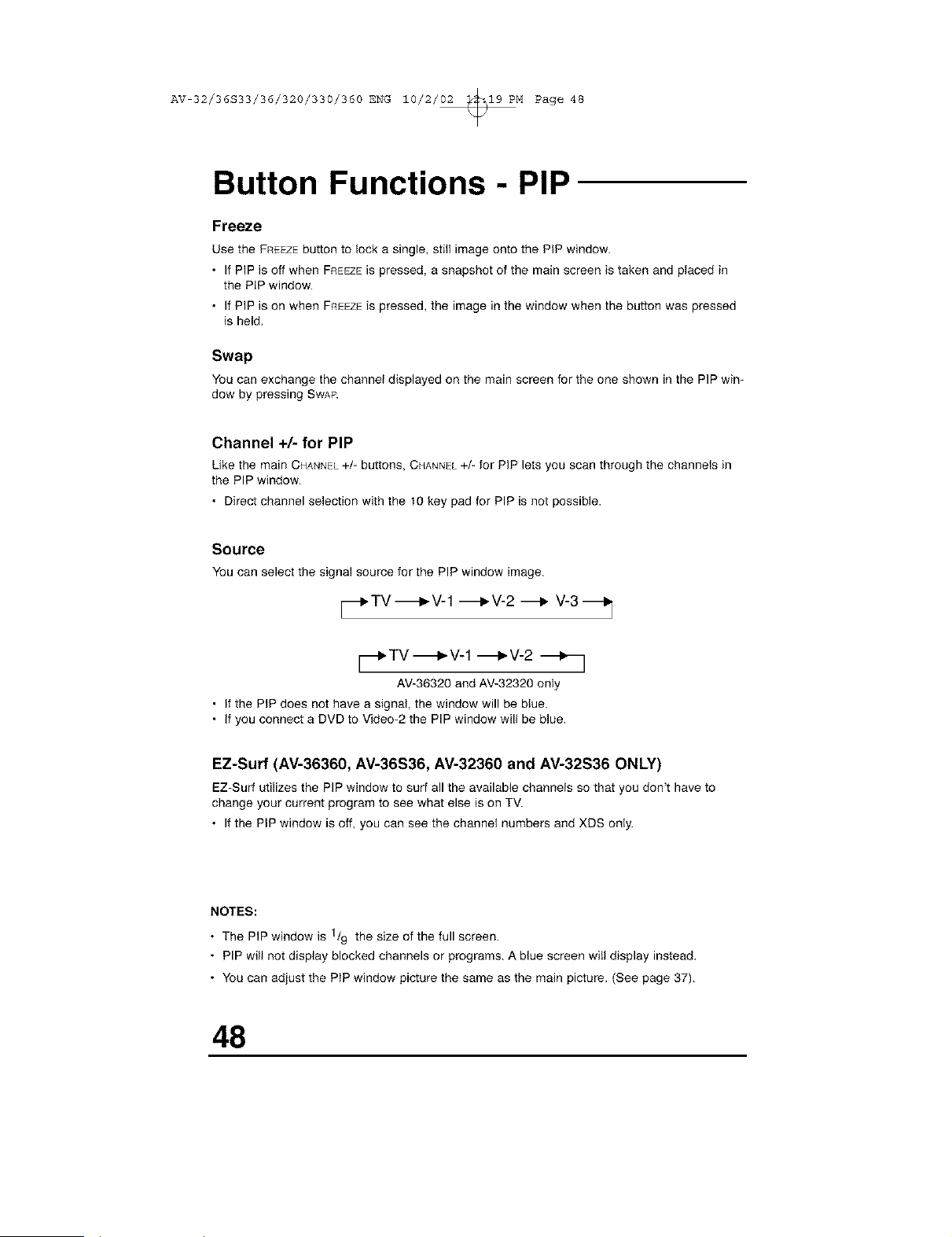
AV 32/36S33/36/320/330/360 ENG 10/2/02 _19 PM Page 48
Button Functions - PIP
Freeze
Use the FREEZEbutton to lock a single, still image onto the PiP window.
• If PIP is off when FREEZEis pressed, a snapshot of the main screen is taken and placed in
the PIP window.
• If PIP is on when FREEZEiS pressed, the image in the window when the button was pressed
is held,
Swap
Youcan exchange the channel displayed on the mainscreen for the one shown inthe PIP win-
dow by pressing SWAP.
Channel +/- for PIP
Like the main CHANNEL+/- buttons, CHANNEL+/- for PiP lets you scan through the channels in
the PIP window.
• Direct channel selection with the t0 key pad for PIP is not possible.
Source
Youcan select the signal source for the PIP window image.
_'TV_V-1 _V-2 _ V-3_]
_TV-_P,V-1 -_V-2 _-_
AV-36320andAV-32320only
• if the PIP does not have a signal, the window will be blue.
• if you connect a DVD to Video-2 the PIP window will be blue.
EZ-Surf (AV-36360, AV-36S36, AV-32360 and AV-32S36 ONLY)
EZ-Surfutilizes the PIP window to surf all the available channels so that you don_thave to
change your current program to see what else ison TV.
• If the PiPwindow is off, you can see the channel numbers and XDS only.
NOTES:
The PIP window is 1/9 the size of the full
screen.
• PIP will not display blocked channels or programs. A blue screen will display instead.
• You can adjust the PIP window picture the same as the main picture. (See page 37).
48
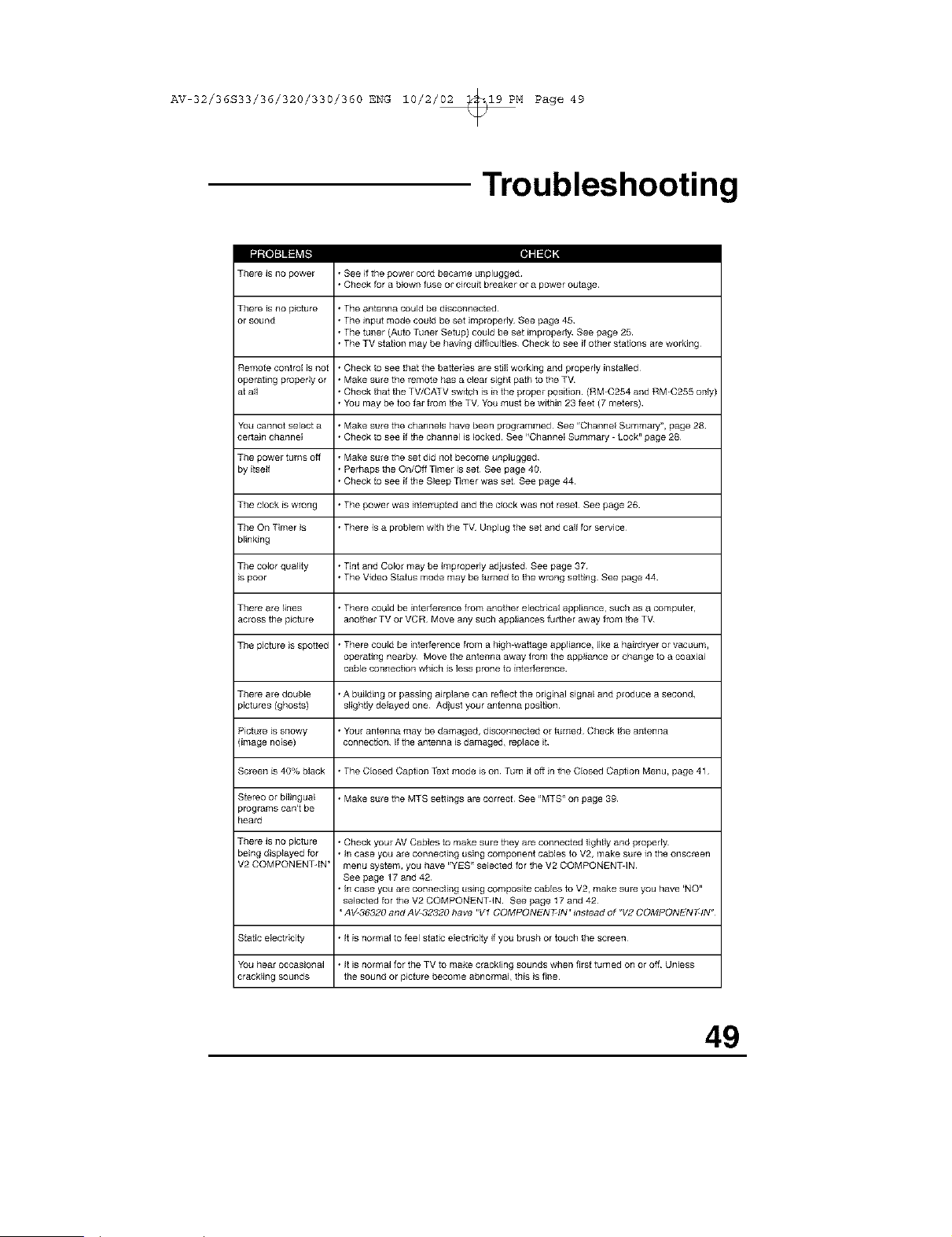
AV 32/36S33/36/320/330/360 ENG 10/2/02 _19 PM Page 49
Troubleshooting
The_ is no power
111
• See ifthe powel coi_ became unplugged
• Check fora blown fuse ol circuitbteakel ol a power outage
There is no p ctule * The antenna could be disconnected
or sound * The input mode could be set impropefly_ See page 45
• The tuner (Auto Tuner Setup} could be set [mproperl_ See page 25
• The TV station may be having difficulties Check to see if other stations are working
Remote controE is not • Check to see that the batteries are stJ]Jworking and properly installed
operating p_per_y or • Make sure the remote has a clear sight path to the T_
at aft • Check that the TV/CATV switch is in the proper position (RM_C254 and RM_C255 only)
• You may be too far from the TV_ You must be within 23 feet (7 metels)
You cannot select a • Make sure the channels have been programmed¸ See 'rChanneE Summary< page 28
cer[ain channel • Check to see if the channel is locked¸ See "Channel Summary - Lock" page 28
The power turns off • Make sure the set did not become unplugged
by itself • Perhaps the On/Off Timer is set See page 40
• Check to see ifthe Sleep Timer was set See page 44
The clock is wrong • The power was [nferrupfed and the clock was not reset¸ See page 26
The On Timer }s • There is a problem with the TV_ Unplug the set and call for service¸
blinking
The color quality • Tint and Color may be improperly adjusfed See page 37
_spoor • The Video Status mode may be turned to the w_ng setting¸ See page 44
The_ are lines • There couJd be inter ference from another electrical appliance_ such as a computer,
across the picture another TV or VCR Move any such appl}ances further away from the TV_
The picture }s spotted • There could be interference from a high-wattage appliance, like a hm_dryer or vacuum,
operating nearb_ Move the antenna away from the appliance or change to a coaxia_
cable conr_ection which Jsless p_one to infer ference
The_ are double • A building or passing a_rp]ane can reflect the original signal and ploduce a second,
pictures (ghosts} slightly delayed one Ad}ust your antenna position¸
Picture is snowy • YotJr antenna may be damaged, disconnected or turned Check the antenna
{image noise) connection If the antenna is damaged, replace it
Screen is 40% black • The Closed Caption Text mode }s on Turn it off }n the Closed Caption Menu, page 41
Stereo or bil}ngual • Make sure the MTS settings a_ correct¸ See "MTS" on page 39
p_grams can't be
hea_
The_ is no picture • Check your AV Cables to make sure they are connecfed tightly and ploped_
being displayed for • in case you are conrlecting using component cables to V2, make sure in the onscreen
V2 COMPONENT-IN* menu system, you have 'ryEs_' selected for the V2 COMPONENiqN
See page 17 and 42
• in case you are connecting using composffe cables to V2, make su_ you have 'NO"
selected for the V2 COMPONENiqN See page 17 and 42
AV-36320 and AV 32320 have "V1 COMPONEN F-IN'r _nstead of _V2 COMPONEN FqN_
Static electricity • it is normal to feel static electricity if you brush or touch the sc_en
You hear OCCaSional • It is normal for the TV to make crackling sounds when firs[ turned on or off Unless
crackling sounds the sound or picture become abnormal, this }s fine¸
49
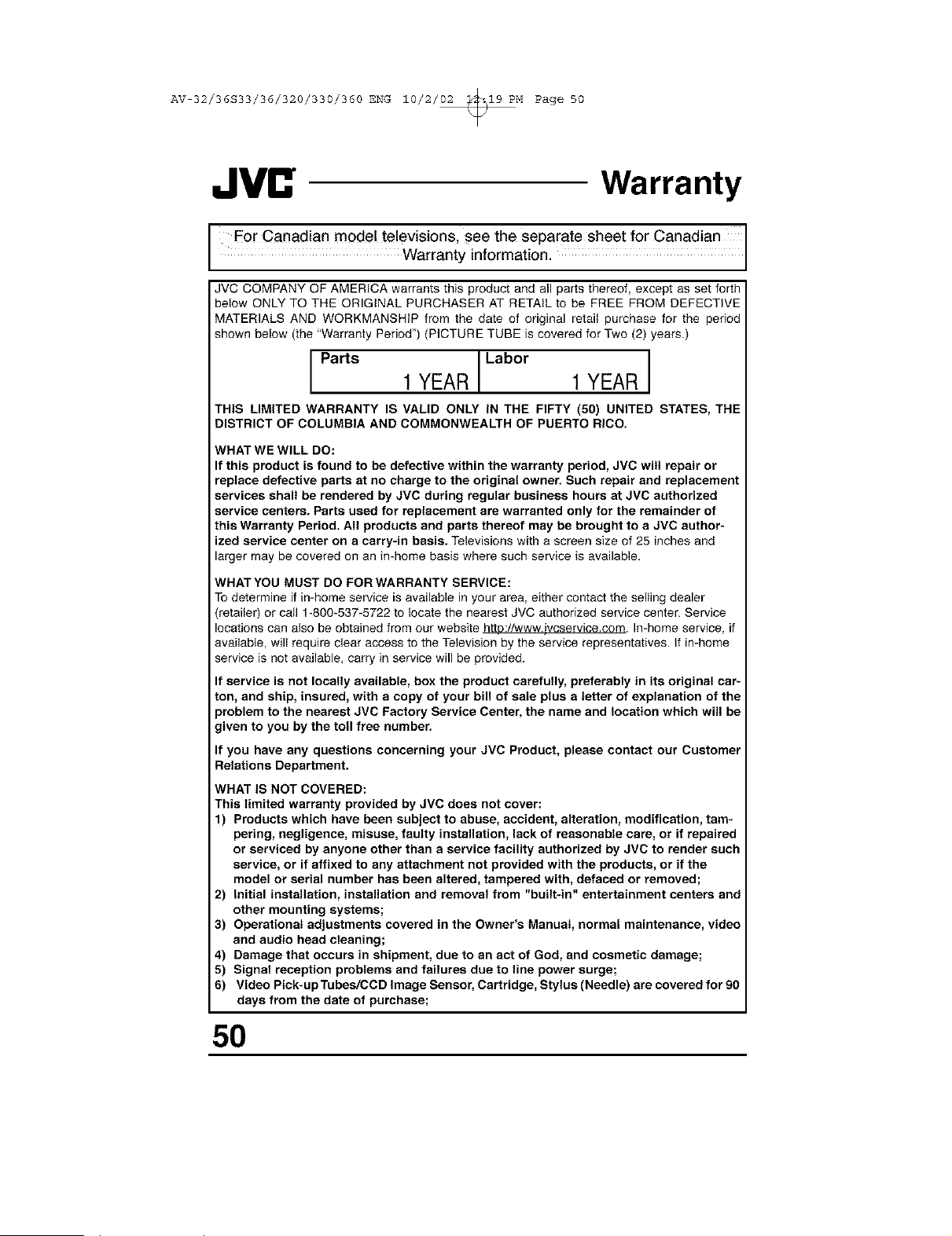
AV 32/36S33/36/320/330/360 ENG 10/2/02 _19 PM Page 50
Warranty
F0r Canadian model televisions, see the separate sheet for Canadian
Warranty information.
JVC COMPANY OF AMERICA warrants this product and all parts thereof, except as set forth
below ONLY TO THE ORIGINAL PURCHASER AT RETAIL to be FREE FROM DEFECTIVE
MATERIALS AND WORKMANSHIP from the date of original retail purchase for the period
shown below (the "Warranty Period") (PICTURE TUBE is covered for Two (2) years.)
Parts I Labor
1 YEAR 1 YEAR
THIS LIMITED WARRANTY IS VALID ONLY IN THE FIFTY (50) UNITED STATES, THE
DISTRICT OF COLUMBIA AND COMMONWEALTH OF PUERTO RICO.
WHAT WE WILL DO:
If this product is found to be defective within the warranty period, JVC wilt repair or
replace defective parts at no charge to the original owner. Such repair and replacement
services shall be rendered by JVC during regular business hours at JVC authorized
service centers. Parts used for replacement are warranted only for the remainder of
this Warranty Period. All products and parts thereof may be brought to a JVC author-
ized service center on a carry-in basis. Televisions with a screen size of 25 inches and
larger may be covered on an in-home basis where such service is available.
WHATYOU MUST DO FOR WARRANTY SERVICE:
To determine if in-home service is available in your area, either contact the setling dealer
(retailer) or call 1-800-537-5722 to locate the nearest JVC authorized service center. Service
locations can also be obtained from our website http://www.jvcservice.com. In-home service, if
available, will require clear access to the Television by the service representatives. If in-home
service is not available, carry in service will be provided.
If service is not locally available, box the product carefully, preferably in its original car*
ton, and ship, insured, with a copy of your bill of sale plus a letter of explanation of the
problem to the nearest JVC Factory Service Center, the name and location which will be
given to you by the toll free number.
If you have any questions concerning your JVC Product, please contact our Customer
Relations Department.
WHAT IS NOT COVERED:
This limited warranty provided by JVC does not cover:
1) Products which have been subject to abuse, accident, alteration, modification, tam-
pering, negligence, misuse, faulty installation, tack of reasonable care, or if repaired
or serviced by anyone other than a service facility authorized by JVC to render such
service, or if affixed to any attachment not provided with the products, or if the
model or serial number has been altered, tampered with, defaced or removed;
2) Initial installation, installation and removal from "built-in" entertainment centers and
other mounting systems;
3) Operational adjustments covered in the Owner's Manual, normal maintenance, video
and audio head cleaning;
4) Damage that occurs in shipment, due to an act of God, and cosmetic damage;
5) Signal reception problems and failures due to line power surge;
6) VideoPick.upTubes/CCDImageSensor, Cartridge, Stytus(Needle)arecoveredfor90
days from the date of purchase;
50
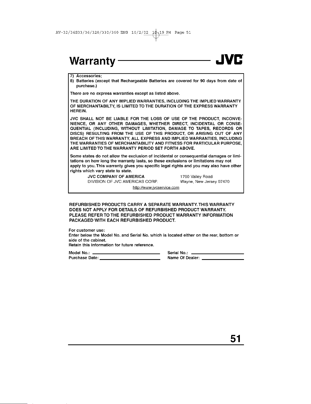
AV 32/36S33/36/320/330/360 ENG 10/2/02 _19 PM Page 51
Warranty
7) Accessories;
8) Batteries (except that Rechargeable Batteries are covered for 90 days from date of
purchase.)
There are no express warranties except as listed above.
THE DURATION OF ANY IMPLIED WARRANTIES, INCLUDING THE IMPLIED WARRANTY
OF MEBCHANTABILTY, IS LIMITED TO THE DURATION OF THE EXPRESS WARRANTY
HEREIN.
JVC SHALL NOT BE LIABLE FOR THE LOSS OF USE OF THE PRODUCT, INCONVE=
NIENCE, OR ANY OTHER DAMAGES, WHETHER DIRECT, INCIDENTAL OR CONSE=
QUENTIAL (INCLUDING, WITHOUT LIMITATION, DAMAGE TO TAPES, RECORDS OR
DISCS) RESULTING FROM THE USE OF THIS PRODUCT, OR ARISING OUT OF ANY
BREACH OF THIS WARRANTY, ALL EXPRESS AND IMPLIED WARRANTIES, INCLUDING
THE WARRANTIES OF MERCHANTABILITY AND FITNESS FOR PARTICULAR PURPOSE.
ARE LIMITED TO THE WARRANTY PERIOD SET FORTH ABOVE.
Some states do not allow the exclusion of incidental or consequential damages or limi
tations on how long the warranty lasts, so these exclusions or limitations may not
appty to you.This warranty gives you specific legal rights and you may also have other
rights which vary state to state.
JVC COMPANY OF AMERICA 1700 Valley Road
DiViSiON OF JVC AMERICAS CORP. Wayne, New Jersey 07470
http://www.ivcservice.com
REFURBISHED PRODUCTS CARRY A SEPARATE WARRANTY. THIS WARRANTY
DOES NOT APPLY FOR DETAILS OF REFURBISHED PRODUCT WARRANTY.
PLEASE REFER TO THE REFURBISHED PRODUCT WARRANTY INFORMATION
PACKAGED WITH EACH REFURBISHED PRODUCT.
For customer use:
Enter below the Model No. and Serial No. which is located either on the rear, bottom or
side of the cabinet.
Retain this information for future reference.
Model No.: Serial No.:
Purchase Date: Name Of Dealer:
51
AV 32/36S33/36/320/330/360 ENG 10/2/02 _19 PM Page 52
Authorized Service Centers
OOAL,T JVL" SERV,OE
HOW TO LOCATE YOUR JVC SERVICE CENTER
TOLL FREE: 1 (800) 537-5722
http://www.jvc,com
Dear Customer,
In order to receive the most satisfaction from your purchase, please read the
instruction booklet before operating the unit. In the event that repairs are neces-
sary, please call 1 (800) 837-8722 for your nearest authorized servicer or visit
our website at www.JVC.com
Remember to retain your Bill of Sale for Warranty Service.
Do not service the television yourself
Caution
To prevent electrical shock, do not open the cabinet. There are no user serviceable
parts inside. Please refer to qualified service personnel for repairs.
Accessories
To purchase accessories for your JVC product, please call toll free: 1 (800) 882-
2345 or on the web at www.JVO.com
For service in Canada
To locate your local JVC service center or dealer in Canada please call:
In Eastern Canada: In Western Canada: En Fran_ais (Montreal):
1 (416) 293-1311 1 (604) 270-1311 1 (814) 871-1311
Or visit us on the web at www.JVC.ca
52
AV 32/36S33/36/320/330/360 ENG 10/2/02 _19 PM Page 53
Search Codes
NOTE: Except for AV-36320 and AV-32320
Cable/Satellite Search Codes Function:
t) Slide the first 2-Way Mode Selector switch to CATV.
2) Press the TV POWERand RETURN+buttons. Hold for at least three seconds and release.
3) Press TV POWER,see if the CATV or Satellite box responds.
4) If there was a response, press RETURN+.The operating codes are now set. If there was no
response, repeat Step 3. If you repeat Step 3 a total of 52 times without a response, use
the remote control which came with the equipment.
5) Press RETURN+to exit.
VCR Search Codes Function:
t) Slide the first 2-way selector switch to "TV" and the other 2-way selector switch to 'VCR".
2) Press the VCR POWERand RETURN+buttons. Hold for at least three seconds and release.
3) Press VCR POWER,see if the VCR responds.
4) If there was a response, press RETURN+.The operating codes are now set. If there was no
response, repeat Step 3. If you repeat Step 3 a total of 80 times without a response, use
the
manufacturers remote control which came with the VCR.
5) Press RETURN+to exit.
DVD Player Search Codes Function:
t) Slide the first 2-way selector switch to '_TV" and the other 2-way selector switch to "DVD".
2) Press the DVD POWERand RETURN+buttons. Hold for at least three seconds and release.
3) Press DVD POWER,see if the DVD player responds.
4) If there was a response, press RETURN+.The operating codes are now set. If there was no
response, repeat Step 3. If you repeat Step 3 a total of 30 times without a response, use
the manufacturers remote control which came with the DVD player.
5) Press RETURN+to exit.
53
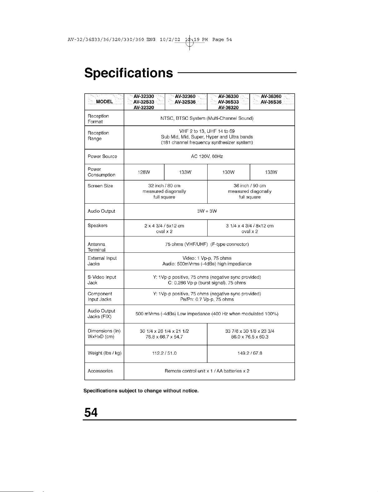
AV 32/36S33/36/320/330/360 ENG 10/2/02 _19 PM Page 54
Specifications
AV-32330 AV-32360 AV-36330 AV-36360
MODEL . AV-32S33 AV-32S36 AV-36S33 AV-36S36
AV+32320 AV-36320
Reception NTSC, BTSC System (Multi-Channel Sound)
Format
Reception VHF 2 to 13, UHF 14 to 69
Range Sub Mid+ Mid, Super, Hyper and Ultra bands
(181 channel frequency synthesizer system)
Rower Source AC 120V. 60Hz
Rower
128W 133W 130W 133W
Consumption
Screen Size 32 inch / 80 cm 36 inch / 90 cm
measured diagonally measured diagonally
full square full square
Audio Output 3W + 3W
Speakers 2 x 4 3/4 / 5xl 2 cm 3 1/4 x 4 3/4 / 8xl 2 cm
oval x 2 oval x 2
Antenna 75 ohms (VHF/UHF) (F-type connector)
Terminal
External Input Video: 1 Vp+p, 75 ohms
Jacks Audio: 500mVrms (+4dBs) high impediance
S-Video input Y: lVp-p positive, 75 ohms (negative sync provided)
Jack C: 0.286 Vp+p (burst signa0, 75 ohms
Component Y: lVp-p positive, 75 ohms (negative sync provided)
Input Jacks PB/RR: 07 Vp-p, 75 ohms
Audio Output
Jacks (FIX) 500 mVrms (-4dBs) Low impedance (400 Hz when modulated 100%)
Dimensions (In) 30 1/4 x 26 1/4 x 21 1/2 33 7/8 x 30 1/8 x 23 3/4
WxHxD (cm) 768 x 66.7 x 54.7 860 x 76.5 x 60.3
Weight (Ibs / kg) 112.2 / 51.0 149.2 / 67.8
Accessories Remote control unit x 1 /AA batteries x 2
Specifications subject to change without notice.
54

AV 32/36S33/36/320/330/360 ENG 10/2/02 _19 PM Page 55
Note
55
AV 32/36S33/36/320/330/360 ENG 10/2/02 _19 PM Page 56
JVC COMPANY OF AMERICA
Division of JVC Americas Corp.
1700 Valley Road
Wayne, New Jersey, 07470
JVI
JVC CANADA, INC.
21 Finchdene Square
Scarborough, Ontario
Canada, MIX 1A7

