Loading ...
Loading ...
Loading ...
• Slide belt off the variable-speed pulley as you lift
the pulley up and out through battery tray opening.
• Remove the rear idler pulley from the double- idler
bracket while unrouting the belt from around both
the rear and the front idler pulley. See Figure 13.
• Remove the hex bolt from the center of the engine
pulley and gently lower it off of the engine
crankshaft. Be careful not to lose any washers or
spacers which may be on top of the engine pulley.
• When remounting the engine pulley, torque the
center hex bolt to between 38 foot-pounds and 50
foot-pounds.
• Remove the drive belt by feeding it from both ends
toward the front idler pulley on the double-idler
bracket. See Figure 14.
• Reassemble by following the above steps in
reverse order.
• Reroute the new belt around the pulleys, belt
keepers and keeper pins EXACTLY as the old one
was routed. Refer to Figure 13.
The drive pedal is properly adjusted when the hole
found in the double-idler bracket has approximately
1-3/8" of travel with ten pounds of pressure applied to
the drive pedal. See Figure 14.
Double Idler
Bracket
Frontof Tractor_
NOTE: View shown from above tractor.
Figure 14
Adjust the drive pedal after replacing the drive belts on
your tractor, if necessary, as follows:
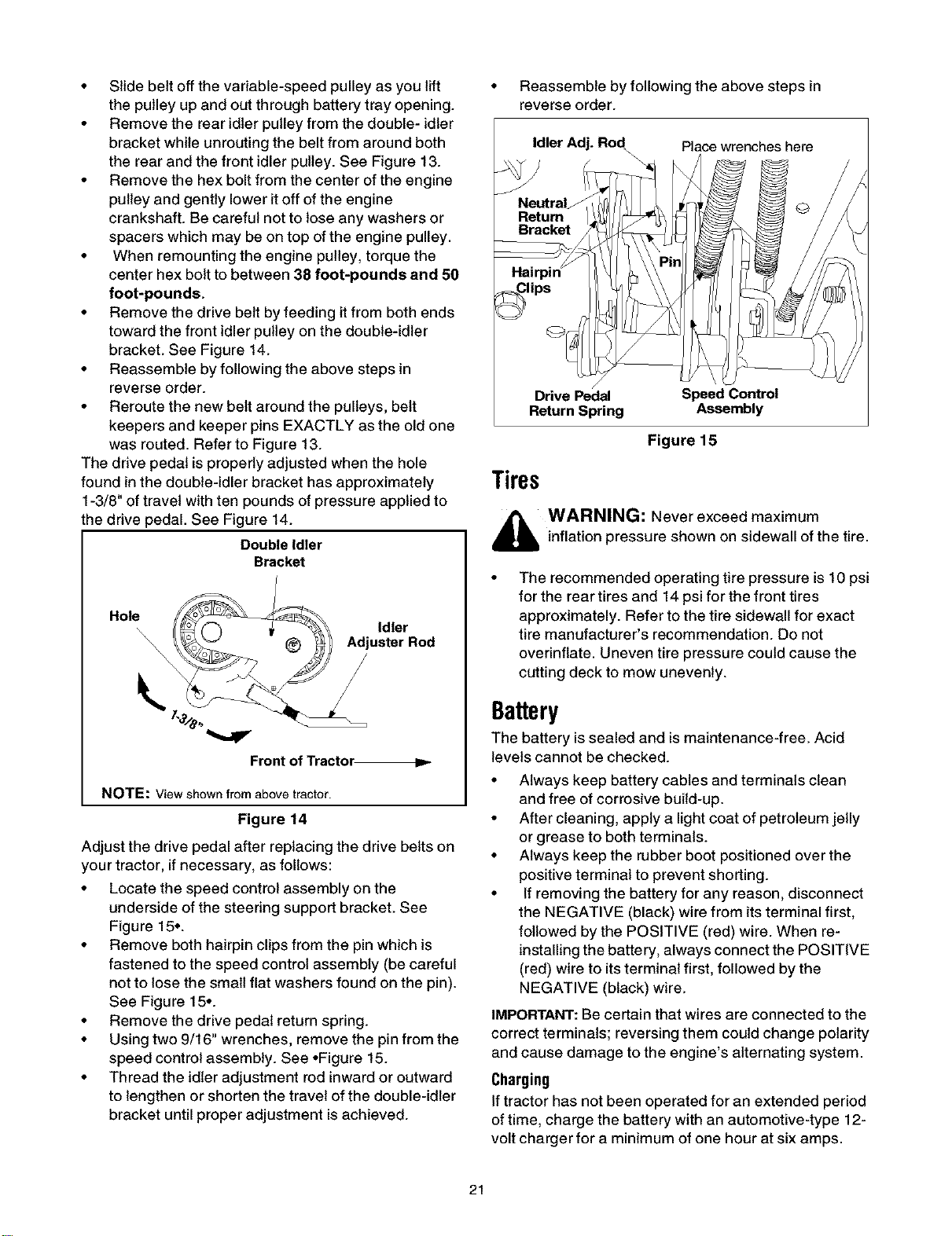
• Locate the speed control assembly on the
underside of the steering support bracket. See
Figure 15..
• Remove both hairpin clips from the pin which is
fastened to the speed control assembly (be careful
not to lose the small flat washers found on the pin).
See Figure 15..
• Remove the drive pedal return spring.
• Using two 9/16" wrenches, remove the pin from the
speed control assembly. See .Figure 15.
• Thread the idler adjustment rod inward or outward
to lengthen or shorten the travel of the double-idler
bracket until proper adjustment is achieved.
• Reassemble by following the above steps in
reverse order.
Idler Adj. Rod Place wrenches here
/
Drive Pedal Speed Control
Return Spring Assembly
Figure 15
Tires
,_ WARNING: Never exceed maximum
inflation pressure shown on sidewall of the tire.
The recommended operating tire pressure is 10 psi
for the rear tires and 14 psi for the front tires
approximately. Refer to the tire sidewall for exact
tire manufacturer's recommendation. Do not
overinflate. Uneven tire pressure could cause the
cutting deck to mow unevenly.
Battery
The battery is sealed and ismaintenance-free. Acid
levels cannot be checked.
• Always keep battery cables and terminals clean
and free of corrosive build-up.
• After cleaning, apply a light coat of petroleum jelly
or grease to both terminals.
• Always keep the rubber boot positioned over the
positive terminal to prevent shorting.
• Ifremoving the battery for any reason, disconnect
the NEGATIVE (black) wire from itsterminal first,
followed by the POSITIVE (red) wire. When re-
installing the battery, always connect the POSITIVE
(red) wire to its terminal first, followed by the
NEGATIVE (black) wire.
IMPORTANT: Be certain that wires are connected to the
correct terminals; reversing them could change polarity
and cause damage to the engine's alternating system.
Charging
If tractor has not been operated for an extended period
of time, charge the battery with an automotive-type 12-
volt charger for a minimum of one hour at six amps.
21
Loading ...
Loading ...
Loading ...