Loading ...
Loading ...
Loading ...

13
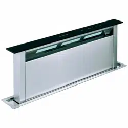
Installation - assembly instructions
The instructions given below in numerical order refer to the drawings in the "assembly instructions"
manual, containing the respective numbering.
1. Make a 842x100 mm rectangular hole behind the hob, to enable insertion of the hood.
IMPORTANT: Make sure the overall dimensions of the hood and hob are compatible with the cabinet
and therefore that installation is feasible.
Maintain a minimum distance of 70 mm from the hob.
Before making the hole, make sure the structure of the cabinet or other parts that could create
problems for correct installation are not present in the hood zone inside the cabinet.
2. Remove the extraction unit from the main body of the hood by undoing the 8 fixing screws.
3. Install the hood in the hole, inserting it from above.
4. Fix the 2 brackets (supplied) to the main hood body. Undo the 4 ØM4x10 screws already fitted on the
hood and fix the brackets.
IMPORTANT: Position the brackets so that a distance of 2 mm remains between the lower part of
the brackets and the bottom of the cabinet. This distance allows the hood to be pulled downwards at
the time of fixing, to ensure perfect adherence of the stainless steel frame to the worktop.
5. Fix the hood inside the cabinet, operating on the 2 brackets, using the 2 washers and 2 Ø3.5x9.5
screws supplied.
IMPORTANT: Before fitting the screws in the cabinet, make sure the product is perfectly
perpendicular to the worktop.
6. Fit the extraction unit, adjusting the air outlet to the required position upwards or downwards.
7. Make a 150 mm diameter hole in the cabinet for the air outlet ducting.
IMPORTANT: Locate the best position according to the particular conformation.
8. Fit the air outlet ducting.
IMPORTANT: The extraction pipe is not supplied and must be purchased.
Avoid drastic changes of direction.
Use a pipe in approved material and having a constant width of 150 mm for its entire length.
9. Connect the electrical connectors of the metal box to the hood (pushbutton panel connector, 9-pin
connector, neon connector) and the extraction unit to the metal box (6-pin connector).
10. Position the metal box containing the electronic components so as not to hinder the air outlet ducting.
11. Connect the hood to the power supply and press the red reset button on the metal box.
12. Press the ON button (T5) on the control panel to open the extraction panel, remove the hood
protection devices and lock the door.
Loading ...
Loading ...
Loading ...