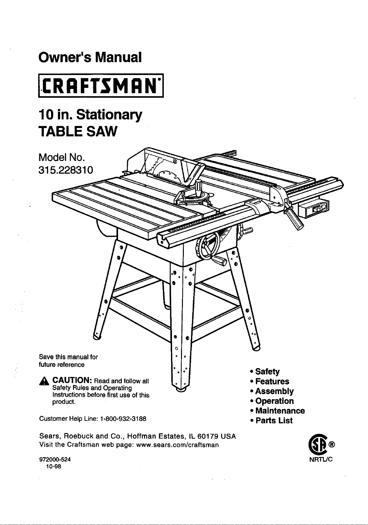
Owner's Manual
10 in. Stationary
TABLE SAW
Model No.
315.228310
Save this manual for
future reference
_, CAUTION: Read and follow all
Safety Rules and Operating
Instructions before first use of this
product.
".I
Customer Help Line: 1-800-932-3188
Sears, Roebuck and Co., Hoffman Estates, IL 60179 USA
Visit the Craftsman web page: www.sears.com/craftsman
972000-524
10-98
• Safety
• Features
• Assembly
• Operation
• Maintenance
• Parts List
NRTL/C
FULLONEYEARWARRANTYONCRAFTSMANTABLESAW
IfthisrRRFTSMRN Table Saw failsdue to a defect in material or workmanshipwithinone year fromthe date of
purchase.Sears willrepair it, free ofcharge,
Contacta Sears Service Center for repair.
If this productis used forcommercialor rentalpurposes,this warrantyappliesonlyfor 90 days fromthe date of
purchase.
This warrantygives you specificlegal dghts,and you may also have other rightswhichvary from state to state.
Sears, Roebuck and Co., Dept. 81"IWA, Hoffman Estates, IL 60179
Yoursaw has manyfeatures for makingcuttingoperationsmore pleasant and enjoyable. Safety,performance
and dependabilityhave been giventop priorityinthe design of thissaw makingiteasy to maintainand operate.
_, CAUTION: Carefully read throughthis entireowner's manual beforeusingyournew saw. Pay close
attentiontothe Rules ForSafe Operation and all Safety AlertSymbols,includingDanger,Wam ng and
Caution. If you useyour saw properlyand onlyfor what it isintended,you willenjoyyears of safe, reliable
service.
._ Lookfor thissymboltopoint outimportantsafety precautions.It means attention!!!Yoursafetyis involved.
WARNING:
The operationof any powertoolcan resultin foreign objects beingthrownintoyoureyes,
whichcan resultin severe eye damage. Beforebeginningpowertooloperation,always
wear safety gogglesor safety glasses with side shieldsand a full face shieldwhen needed.
We recommenda Wide Vision Safety Mask for useover eyeglasses or standardsafety
glasses withside shields,available at Sears Retail Stores.
• Warranty and Introduction.............................................................................................................................. 2
• Table Of Contents ....................................................................................................................................... 2-3
• Rules For Safe Operation ........................................................................................................................... 4-6
• Electrical......................................................................................................................................................... 7
• Glossaryand ProductSpecifications............................................................................................................. 8
• Unpackingand Accessories........................................................................................................................... 9
• Loose Parts List...................................................................................................... ...................................... 10
• Small Parts List ....................................................................................................................................... 11-12
• Tools Needed ............................................................................................................................................... 13
• Labels...................................................................................................................................................... 14-15
• Features .................................................................................................................................................. 16-17
• Assembly................................................................................................................................................. 18-27
InstallingHandwheels on Table Saw Base.................................................................................................. 18
AssemblingLeg Stand ............................................................................................................................ 18-19
CRAFTSMAN"TABLESAW315.228310 2
MountingtheLegStandontheTableSawBase........................................................................................ 19
AssemblingTable Extensions...................................................................................................................... 20
AligningTable Extensions............................................................................................................................ 20
Installingthe Rear Rail................................................................................................................................. 21
Installingthe Front Rail ................................................................................................................................ 22
AligningRip Fence and Front Rail ............................................................................................................... 23
Mountingthe Motor ...................................................................................................................................... 23
Installingthe Belt and Belt Guard ................................................................................................................ 24
Checkingthe Throat Plate............................................................................................................................ 24
Installingthe Blade Guard............................................................................................................................ 25
Aligningthe RivingKnifewith the Blade ...................................................................................................... 26
Checking Rip Fence and BladeAlignment .................................................................................................. 27
• Adjustments............................................................................................................................................. 28-32
Replacingthe Blade ..................................................................................................................................... 28
Heeling(Paralleling) the Sawblade to MiterGage Groove........................................ t............................ 29-30
Settingthe Bevel Stops and Indicator..................................................................................................... 30-31
Adjustingthe Miter Gage .............................................................................................................................. 31
Removing/ Replacing the Throat Plate ....................................................................................................... 32
• BasicOperation/bfthe Table Saw .......................................................................................................... 33-40
Causes of Kickback...................................................................................................................................... 33
AvoidingKickback........................................................................................................................................ 33
Making CuttingAids ..................................................................................................................................... 33
Types of Cuts ............................................................................................................................................... 34
Making a Cross Cut ...................................................................................................................................... 35
Making a Rip Cut .......................................................................................................................................... 35
Making a Miter Cut ....................................................................................................................................... 36
Making a Bevel CrossCut ............................................................................................................................ 36
Making a Bevel Rip Cut................................................................................................................................ 37
• Making a Compound(Bevel) Miter Cut ........................................................................................................ 38
Making a Large Panel Cut ............................................................................................................................ 39
Making a Non-Through Cut .......................................................................................................................... 39
Making a Dado Cut................................................. _..................................................................................... 40
• Maintenance................................................................................................................................................. 41
• Lubrication.................................................................................................................................................... 41
• Troubleshooting....................................................................................................................................... 42-44
• ExplodedView and Repair Parts List...................................................................................................... 46-63
• PartsOrdering / Service ................................................................................................................... backpage
3 CRRFTSMIIN"TABLESAW315.228310
The purpose ofsafety symbolsisto attractyourattentionto possibledangers.The safety symbols,and the
explanationswiththem, deserve yourcarefulattentionand understanding.The safetywarningsdo not by
themselves eliminateany danger. The instructionsor warningsthey give are not substitutesfor properaccident
preventionmeasures.
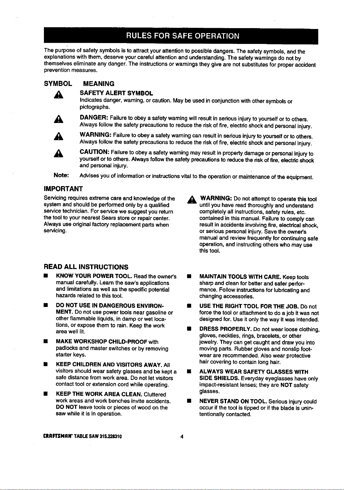
SYMBOL MEANING
A
A
A
Note:
SAFETY ALERT SYMBOL
Indicatesdanger, warning,or caution,May be used inconjunctionwithothersymbolsor
pictographs.
DANGER: Failureto obey a safety warningwill resultin seriousinjurytoyourselforto others.
Alwaysfollow the safety precautionsto reducethe riskoffire, electdcshockand personalinjury.
WARNING: Failureto obeya safety warningcan resultinsedousinjurytoyourselfor to others.
Always follow the safety precautionsto reducethe riskoffire, electdcshockand personalinjury.
CAUTION: Failureto obey a safetywarningmay resultin propertydamage or personalinjuryto
yourselfor to others.Alwaysfollowthe safety precautionsto reducetheriskoffire, electricshock
and personalinjury.
Advisesyou of informationor instructionsvital tothe operationor mainienance ofthe equipment.
IMPORTANT
Servicingrequiresextreme care and knowledgeofthe
systemand shouldbe performedonlybya qualified
servicetechnician.For servicewe suggestyou return
the toolto yournearest Sears store or repaircenter.
Always useoriginalfactory replacementpartswhen
servicing.
_1= WARNING: Do notattemptto operatethistool
untilyou have read thoroughlyand understand
completelyall instructions,safety rules, etc.
containedin this manual. Failuretocomplycan
resultin accidentsinvolvingfire, electricalshock,
or seriouspersonalinjury.Save the owner's
manual and reviewfrequently for continuingsafe
operation,and instructingotherswho may use
this tool.
READ ALL INSTRUCTIONS
KNOW YOUR POWER TOOL. Read the owner's
manual carefully.Learnthe saw's applications
and limitationsas well as the specificpotential
hazards relatedto thistool.
DO NOT USE IN DANGEROUS ENVIRON-
MENT. Do not use powertoolsnear gasolineor
otherflammable liquids,in damp or wet loca-
tions,or expose them to rain. Keep the work
area well lit.
• MAKE WORKSHOP CHILD-PROOF with
padlocksand masterswitches or by removing
starter keys.
• KEEP CHILDREN AND VISITORS AWAY. All
visitorsshouldwear safety glasses and be kepta
safe distancefrom work area. Do not let visitors
contacttoolor extensioncordwhileoperating,
• KEEP THE WORK AREA CLEAN. Cluttered
work areas and work benches inviteaccidents,
DO NOT leave toolsor pieces of woodon the
saw while itis in operation,
MAINTAIN TOOLS WITH CARE. Keep tools
sharp and clean for betterand safer perfor-
mance. Followinstructionsforlubricatingand
changingaccessories.
USE THE RIGHT TOOL FOR THE JOB. Do not
force the toolor attachmentto do a job itwas not
designedfor. Use itonlythe way it was intended.
DRESS PROPERLY. Do notwear looseclothing,
gloves, neckties,rings,bracelets,or other
jewelry. They can getcaughtand draw you into
moving parts.Rubberglovesand nonslipfoot-
wear are recommended.Alsowear protective
hair coveringto containlonghair.
ALWAYS WEAR SAFETY GLASSES WITH
SIDE SHIELDS. Everydayeyeglasses have only
impact-resistantlenses;theyare NOT safety
glasses,
NEVER STAND ON TOOL. Seriousinjurycould
occurif thetoolis tippedor ifthe blade is unin-
tentionallycontacted.
CRRFTSMRN"TABLESAW315.228310 4
BIULES FOR SAFE OPERATION (Continued)
B DO NOT OVERREACH. Keep properfootingand
balance at all times.
m
M
M
M
SECURE WORK. Use clamps or a viseto hold
workwhen practical. It'ssaferthan usingyour
handand frees bothhandsto operatetool.
USE THE PROPER EXTENSION CORD. Make
sure yourextensioncord isin goodcondition.
Use onlya cord heavyenoughto carrythe
currentyour productwilldraw. An undersized
cordwillcause a drop in linevoltageresultingin
lossof power and overheating.A wire gage size
(A.W.G.) of at least 14 isrecommendedfor an
extensioncord25 feet or less in length.If in
doubt,use the next heaviergage. The smaller
the gage number,the heavierthe cord.
AVOID ACCIDENTAL STARTING. Be sure
switchisoft when pluggingin.
REMOVE WRENCHES AND ADJUSTING
KEYS. Get in the habitof checking- before
turningon tool- that hexI_eysand adjusting
wrenchesare removedfrom tool.
M
M
M
M
M
CHECK DAMAGED PARTS. Before usingthe
toolagain, checkany damaged parts,including
guards,for properoperationand performance.
Check alignmentofmovingpads, bindingof
movingpads, breakage of pads, saw stability,
mountingand any otherconditionsthat may
affect itsoperation.A damaged part must be
propedyrepairedor replaced bya qualified
servicetechnicianat a Sears store or repair
center to avoid riskofpersonalinjury.
USE ONLY CORRECT BLADES. Use the right
blade size, style and cutting speed for the
material and the type of cut. Blade teeth should
point down toward the front of the table.
USE RECOMMENDED ACCESSORIES, Using
improperaccessoriesmay riskinjury.
USE ONLY SEARS REPLACEMENT PARTS,
Allrepairs,whether electdcalor mechanical,
shouldbe made bya qualifiedservice technician
at a Sears storeor repaircenter.
KEEP GUARDS IN PLACE and in good working
order.This includesthe blade guard, rivingknife,
and anti-kickbackpawls.
CHECK DIRECTION OF FEED. Feed work into
a blade or cutteragainst the directionof rotation
ofthe bladeor cutter only,
DISCONNECT ALL TOOLS. When notin use,
before servicing,or when changingattachments,
blades, bits,cutters,etc., all toolsshouldbe
disconnectedfrom powersupply.
M
M
DO NOT FORCE THE TOOL. It willdo tbejob
better and more safelyat the ratefor whichit
was designed.
NEVER LEAVE TOOL RUNNING UNAT-
TENDED. TURN THE POWER OFF. Do not
leave tool untilit comesto a completestop.
BEFORE MOUNTING, DISCONNECTING OR
REMOUNTING THE MOTOR; unplugthesaw
and removethe switchkey.
A
WARNING: When servicing,useonly identical
Craftsman replacementpads. Use ofany other
parts may create a hazard or cause product
damage.
M
M
M
M
M
M
M
M
M
NEVER USE THIS TOOL IN AN EXPLOSIVE
ATMOSPHERE. Normal sparkingof the motor
could ignitefumes.
MAKE SURE THE WORK AREA HAS AMPLE
LIGHTING to see the work and that no obstruc-
tionswillinterferewithsafe operation BEFORE
performingany work usingthistool.
DO NOT USE TOOL IF SWITCH DOES NOT
TURN IT ON AND OFF. Have defective switches
replaced bya qualifiedservicetechnicianat a
Sears store or repaircenter.
GUARD AGAINST ELECTRICAL SHOCK by
preventingbodycontactwith groundedsurfaces
such as pipes, radiators,ranges, refrigerator
enclosures.
GROUND ALL TOOLS. See Electricalpage.
WEAR A DUST MASK to keep from inhalingfine
particles.
PROTECT YOUR HEARING. Wear hearing
protectiondudngextended periodsof operation.
DO NOT OPERATE THIS TOOL WHILE UN-
DER THE INFLUENCE OF DRUGS, ALCOHOL,
OR ANY MEDICATION.
STAY ALERT AND EXERCISE CONTROL,
Watch whatyou are doingand use common
sense, Do not operate tool when you ere tired.
Do not rush.
AVOID AWKWARD OPERATIONS AND HAND
POSITIONS where a sudden slipcouldcause
your handto moveintothe blade. ALWAYS
make sure you have good balance,
ALWAYS SUPPORT LARGE WORK PIECES
while cuttingto minimize riskof blade pinching
and kickback.Saw may slip,walk or slidewhile
cuttinglarge or heavy boards.
5 CRAFTSMAN"TABLESAW315,228310
RULES FOR SAFE OPERATION (Continued)
• GUARD AGAINST KICKBACK. Kickbackcan
occurwhen the blade sta$$s,ddvingthe work
piece back towardthe operator. Itcan pullyour
hand intothe blade, resultingin sedouspersonal
injury.Stay out ofthe blade path and turn switch
off immediatelyifblade bindsor stalls.
USE A SUPPORT FOR THE SIDES AND BACK
OF THE SAW TABLE when sawingwide or long
workpieces. Use a sturdy"outrigger" supportif a
table extensionis morethan 24 incheslong and
is attached to the saw, to preventtipping.
CUT ONLY WOOD, PLASTIC OR WOOD-LIKE
MATERIALS. Do not cut metal.
• NEVER cutmore than one piece at a time. DO
NOT STACK more than one workpieceon the
saw table at a time.
DO NOT REMOVE THE SAW'S BLADE
GUARDS. Never operate the saw with any guard
or cover removed. Make sure all guardsare
operating propedybefol'eeach use.
NEVER PERFORM ANY OPERATION FREE-
HAND. Always place the workpieceto be cuton
the saw table and position itfirmly againstthe
fence as a backstop.
USE THE RIP FENCE. Always use a fence or
straightedge guide when ripping.
BEFORE MAKING A CUT, be sure all adjust-
mentsare secure.
• BE SURE THE BLADE PATH IS FREE OF
NAILS. Inspectfor and remove all nailsfrom
lumber beforecutting.
• BE SURE THE BLADE CLEARS THE
WORKPIECE. Never startthe saw with the blade
touchingtheworkplace.
• KEEP HANDS AWAY FROM CUTTING AREA.
Do notreach underneathworkor in blade cutting
path withyourhands and fingersfor any reason.
Alwaysturnthe power off.
• USE A PUSHBLOCK OR PUSH STICK for
workpiecessosmall that yourfingersgo under
the blade guam:d.NEVER TOUCH BLADE or
other movingpartsduringuse, for any reason.
_k WARNING: Blade coastsafter beingtumed off.
ALLOW THE MOTOR TO COME UP TO FULL
SPEED beforestartinge cutto avoidblade
bindingor stalling.
ALWAYS PUSH THE WORKP|ECE; never pullit
towardthe saw.
DO NOT FEED THE MATERIAL TOO QUICKLY.
Do notfome the workpieceagainstthe blade.
ALWAYS TURN OFF SAW beforedisconnecting
it,to avoidaccidental startingwhen reconnecting
to powersupply. NEVER leave the table saw
unattendedwhileconnectedto a powersource.
BEFORE CHANGING THE SETUP, REMOVING
COVERS, GUARDS, OR BLADE; unplugthe
saw and remove the switchkey.
KEEP TOOL DRY, CLEAN, AND FREE FROM
OIL AND GREASE. Alwaysuse a clean cloth
when cleaning. Never use brake fluids,gasoline,
petroleum-basedproducts,or any solventsto
clean tool.
KEEP BLADES CLEAN, SHARP AND WITH
SUFFICIENT SET. Sharp bladesminimize
stallingand kickback.
USE ONLY OUTDOOR EXTENSION CORDS.
Use onlyextensioncordswiththe marking
=Acceptable for use with outdoorappliances;
store cordsindoorswhilenot in use."Use
extensioncordswith an electricalratingnot less
than the saw's rating.Always disconnectthe
extensioncordfrom the outletbeforedisconnect-
ingthe productfrom the extensioncord.
• INSPECT TOOL CORDS AND EXTENSION
CORDS PERIODICALLY and, ifdamaged, have
repairedbya qualifiedsewice technicianat a
Sears store or repaircenter. Stay constantly
aware ofcord locationand keep itwell away
fromthe movingblade.
• DO NOT ABUSE CORD, Never yankcord to
disconnectitfrom receptacle. Keep cord from
heat, oil,and sharpedges.
SAVE THESE INSTRUCTIONS. Referto them
frequently and use to instructother users. Ifyou
loansomeonethis tool, loanthem these instruc-
tionsalso.
SAVE THESE INSTRUCTIONS
[RAFTSMRW TABLESAW316,228310 6
EXTENSION CORDS
Use only3-wire extensioncordsthat have 3-prong
groundingplugsand 3-pole receptaclesthat accept
thetool's plug.When usinga powertool at a consid-
erable distancefromthe powersource, use an
extensioncord heavyenoughto carrythe current that
thetool willdraw.An undersizedextensioncordwill
cause a drop in linevoltage, resultingin a loss of
powerand causingthe motorto overheat. Use the
chart providedbelowto determinethe minimumwire
size requiredin an extensioncord. Only roundjack-
eted cordslistedby Underwriter'sLaboratories(UL)
shouldbe used.
Length of Extension Cord Wire Size (A.W.G.)
Up to 25 feet 14
26-100 feet 12
When workingwith thetool outdoors,use an exten-
sioncordthat isdesignedfor outsideuse. This is
indicatedbythe lettersWA on the cord's jacket.
Beforeusing an extensioncord, inspectitfor looseor
exposedwires and cut or worninsulation.
_k CAUTION: Keep the cord away from the cutting
area and positionthe cordsothat it willnot be
caughton lumber,tools,or otherobjectsdudng
cuttingoperations.
ELECTRICAL CONNECTION
YourSears CraftsmanTable Saw ispowered bya
precisionbuiltelectricmotor. Itshouldbe connected
to a power supply that Is 120 volts, 60 Hz, AC only
(normal household current). Do not operate thistool
ondirectcurrent (DC). A substantialvoltagedrop will
causea lossofpower and the motorwilloverheat. If
the saw does not operatewhen plugged intoan
outlet,doublecheckthe power supply.
SPEED AND WIRING
The no-loadspeed of yourtable saw isapproximately
3,600 rpm.This speed isnot constantand decreases
undera load or with lowervoltage. Forvoltage, the
wiringin a shopis as importantas the motor'shorse-
powerrating.A lineintendedonlyfor lightscannot
properlycarry a powertoolmotor. Wire that isheavy
enoughfor a shortdistancewillbe too lightfor a
greaterdistance. A linethatcan supportone power
tool may not be able to supporttwo or three tools.
GROUNDING INSTRUCTIONS
In the event ofa malfunctionor breakdown, grounding
providesa path ofleast resistancefor electriccurrent
to reducethe riskofelectricshock.Thistool is
equippedwith anelectriccordhaving an equipment-
groundingconductorand a groundingplug.The plug
mustbe pluggedintoa matchingoutletthat ispropedy
installedand groundedin accordancewith all local
codes and ordinances.
Do not modifythe plug provided.Ifitwillnot fit the
outlet,have the properoutletinstalledbya qualified
electrician.Improperconnectionofthe equipment-
groundingconductorcan resultin a riskof electric
shook.The conductorwith insulationhaving an outer
surfacethat isgreen withor withoutyellowstripesis
the equipment-groundingconductor. If repairor
replacementofthe electdc cordor plug isnecessary,
do not connect the equipment-groundingconductorto
a liveterminal.
Check witha qualifiedelectricianor service personnel
ifthe groundinginstructionsare notcompletely
understood,or if indoubt as to whetherthetoolis
properlygrounded.
Repair or replacea damaged or worncordimmedi-
ately.
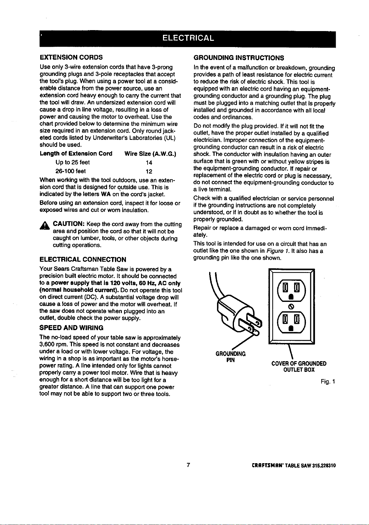
This toolis intendedfor use on a circuitthathas an
outletlikethe one shownin Figure 1.Italso hasa
groundingpinlike the one shown.
GROUNDING
PIN
COVEROFGROUNDED
0UTLETBOX
Fig. 1
7 rRRFTSNRN"TABLESAW31S.228310
Anti-Kickback Pawls
Toothedsafety devicesbehindthe bladedesignedto
stop a workpiece from beingkicked back at the
operatorduringa rippingoperation.
Arbor
The shafton whicha bladeor cuttingtoolis mounted.
Bevel Cut
A cuttingoperationmade withthe blade at any angle
otherthan 90" to the saw table.
Compound Cut
A cutwith both a miterangle and a bevel angle.
Crosscut
A cuttingoperation made acrossthe grain or the width
ofthe workpiece.
Dsdo
A non-throughcut thatgives a square notchortrough;
requiresa specialblade.
Featherboard
A device to helpguide workpiecesduring ripcuts.
Freehand (for table saw)
Dangerous practiceofmaking s cut withoutusingdp
or miterfences. See Safety Rules.
Gum
A sticky, sap-based residuefromwood products.
Heel
Alignmentof the blade.
Kerf
The materialremovedby the blade in a through cutor
the slotproducedby the bladein a non-throughcut.
Kickback
A hazard that can occurwhen blade bindsor stalls,
throwingworkpiece backtowardoperator.
Leading End
The end of the workpiecepushed intothe cuttingtool
first.
Miter Cut
A cuttingoperationmade with the miter gage at any
angle otherthan 0".
Molding
A non-throughcutthat givesa varied shape tothe
workpiece and requirese specialblade.
Push Stick
A device usedto feed the workpiecethroughthe saw
blade duringnarrowcuttingoperations.It helpskeep
the operator'shandswell away from the blade,
Rabbet
A notch inthe edge ofa workpiece.
Resaw
A cuttingoperationto reducethe thicknessofthe
workpieceinorder to make thinnerpieces.
Resin
A sticky,sap-based substance.
RIp Cut
A cut made withthethe grainof the workpiece.
Sswblade Path
The area directlyin linewiththe blade-- over,under,
behind, orin front ofit. Also, theworkpiecearea
whichwillbe or has been cutby theblade.
Set
The distancethat the tip ofthe saw bladetoothis bent
(or set) outwardfrom the face of the blade.
Throw-Back
Saw throwingback a workpiece;similarto kickback,
Through Sawing
Any cuttingoperationwhere the blade extends
completelythroughthe workpiece.
Trailing End
The workpieceend lastcutby the blade in a dp cut.
Workp|ece
The itemon whichthe cutting operationis beingdone.
The surfacesof a workpieceare commonlyreferredto
as faces,ends, and edges.
Worktable
The surfaceon whichthe wodq_ecerestswhile
performinga cuttingoperation.
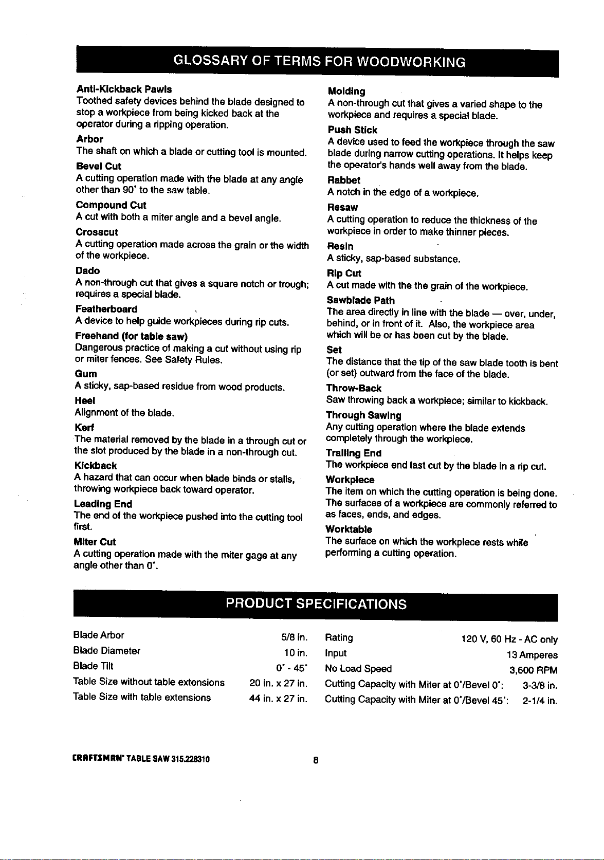
BladeArbor 5/8 in.
Blade Diameter 10 in.
Blade Tilt 0"- 45"
TableSize withouttable extensions 20 in. x 27 in.
Table Size with table extensions 44 in. x 27 in.
Rating 120 V,60 Hz - AC only
Input 13 Amperes
No LoadSpeed 3,600 RPM
CuttingCapacitywithMiter at 0"/Bevel0": 3-3/8 in.
Cutting Capacity withMiter at O'/Bevel45": 2-1/4 in.
rRRFTSNlUI" TABLESAW$1G,228310 8
Your newtable saw has been designedto give you
manyyears of high qualityperformance.To insure
thisgoal, propercare and treatment is important.
Careful treatment beginswith removingall pads from
the cartonand checkingthem againstthe listof loose
parts.The long box containsthe rails. The large box
holdsall other parts,whichare detailed inthe Loose
PartsList.
• Separate the saw and all partsfrom the packing
materialsand checkeach againstthe packing list,
especiallythe small partsthat can be hidden inthe
packingmaterial
Note: Do notdiscard the packingmaterialsuntilyou
have carefullyinspectedthe saw, identifiedall
parts,and satisfactorily operated your new saw.
_IL WARNING: Never use gasoline, naptha, or
other highlyvolatile solvents.Do not ever let
brake fluids, gasoline,petroleum-based
products,or penetratingoilscontact plasticparts.
Such chemicalscan weaken or destroyplastic.
II Remove the wax papercoveringon the table. Use
anyordinary household type grease and spot
remover. Immediatelyapplya coat of automotive
typepaste wax to the table and table exensions.
,_ WARNING: To preventaccidental startingthat
couldcause possibleseriouspersonalinjury,
assemble all partsto yoursaw before connecting
it to power supply.Saw shouldnever be
connected topower supplywhen you are
assemblingparts,makingadjustments,installing
or removingblades, or when notin use.
,_ WARNING: If any partsare missing,do not
operate thistool untilthe missingparts are
replaced. Failuretodo so could resultinpossible
seriouspersonalinjury.
The following recommendedaccessoriesare currentlyavailable
• Fence Guide System
• Guide Master
• Box Joint &Miter Guide
• Universal Jig
• Taper Jig
• 10 in. SandingDisc
• 8 in. SandingDisc
• Elite Dado
• ExcaliburDado
• 7 in. Adj. Dado 36 tip
• 7 in.Adj. Dado 24 tip
at Sears RetailStores.
• 7 in.Stack Steel Dado
• 7 in.x 9/16 in.Stack Dado
• 7 in. MoldingHead Set
• 2 Bit MoldingHead Set
• Saw Baskets
• JointerClamps
• SpecialtyThroat Plate
• Miter Gage Hold DownClamp
• Align-A-RipXRC Rip Fence
• Dust CollectionSystem
,_ WARNING: The useof attachmentsor accessoriesnot listed mightbe hazardous.
9 [RAFTSMAN" TABLESAW315.228310
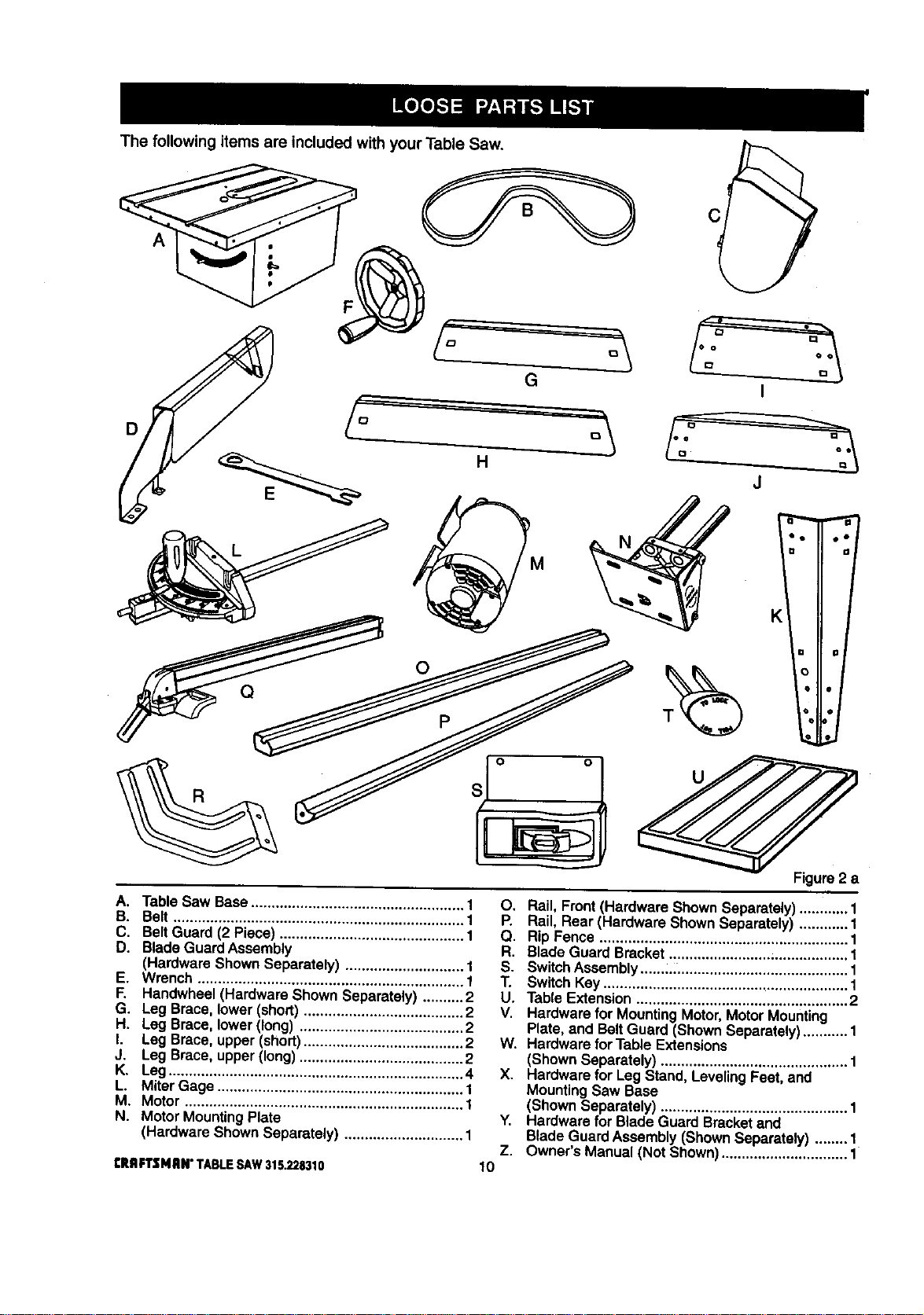
The following items are included with your Table Saw.
A
D
G
o
Q
I
J
Figure2 a
A. Table Saw Base .................................................... 1
B. Belt ....................................................................... 1
C. Belt Guard (2 Piece) ............................................. 1
D. Blade GuardAssembly
(Hardware ShownSeparately) ............................. 1
E. Wrench ................................................................. 1
F. Handwheel(Hardware Shown Separately) .......... 2
G. Leg Brace, lower(short)....................................... 2
H. Leg Brace, lower(long) ........................................ 2
I. Leg Brace, upper(short)....................................... 2
J. Leg Brace, upper (long) ........................................ 2
K. Leg........................................................................ 4
L. MiterGage ............................................................ 1
M. Motor .................................................................... 1
N. Motor MountingPlate
(Hardware Shown Separately) ............................. 1
tRRFTZMRI¢ TABLE SAW 315.228310
O. Rail, Front(Hardware ShownSeparately)............ 1
P. Rail, Rear (Hardware ShownSeparately) ............ 1
Q. RipFence ............................................................. 1
R. Blade Guard Bracket ......................... ;.................. 1
S. SwitchAssembly ......,, ......................................... 1
T. SwitchKey............................................................ 1
U. Table Extension.................................................... 2
V. Hardware for MountingMotor,MotorMounting
Plate, and BeltGuard (ShownSeparately)...........1
W. Hardware for Table Extensions
(ShownSeparately) .............................................. 1
X. Hardware for Leg Stand, LevelingFeet, and
MountingSaw Base
(ShownSeparately) .............................................. 1
Y. Hardware for Blade Guard Bracketand
Blade GuardAssembly(ShownSeparately) ........ 1
Z. Owner's Manual (Not Shown)............................... 1
10
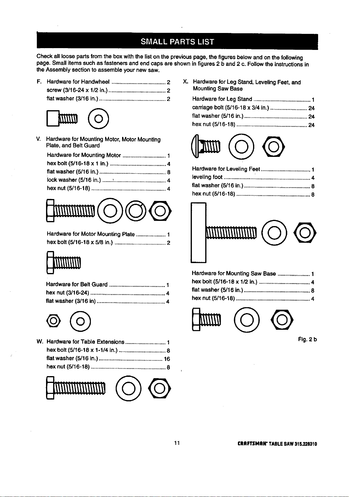
Checkallloosepartsfromtheboxwiththelistonthepreviouspage,thefiguresbelowandonthefollowing
page,Smallitemssuchasfastenersandendcapsareshowninfigures2band2c.Followtheinstructionsin
theAssemblysectiontoassembleyournewsaw.
F. Hardware for Handwheel ................................... 2
screw (3/16-24 x 1/2 in.)..................................... 2
flat washer (3/15 in.)........................................... 2
V.
Hardware for MountingMotor,MotorMounting
Plate, and Belt Guard
Hardware for Mounting Motor ............................ 1
hex bolt (5/16-18 x 1 in.) .................................... 4
flat washer (5/16 in.) ........................................... 8
lock washer (5/16 in.) .......,.................................. 4
hex nut (5/16-18) ................................................ 4
Hardware for Motor MountingPlate ................... 1
hex bolt (5/16-18 x 5/8 in.) ................................. 2
Xo
Hardware for Leg Stand, LevelingFeet, and
MountingSaw Base
Hardware for Leg Stand ..................................... 1
carriage bolt(5/16-18 x 3/4 in.)........................ 24
flat washer (5/16 in.)......................................... 24
hex nut(5/16-18) .............................................. 24
Hardware for LevelingFeet ................................ 1
leveling foot ........................................................ 4
flatwasher (5/16 in.)........................................... 8
hex nut (5/16-18) ................................................ 8
Hardware for Belt Guard .................................... 1
hex nut (3/16-24) ................................................ 4
flat washer (3/16 in) ............................................ 4
W. Hardware for Table Extensions.......................... 1
hex bolt(5/16-18 x 1-1/4 in.).............................. 8
flatwasher (5/16 in.) ......................................... 16
hex nut (5/16-18) ................................................ 8
m
Hardware for MountingSaw Base ..................... 1
hex belt (5116-18 x 1/2 in.) ................................. 4
flat washer (5/16 in°)........................................... 8
hex nut (5116-18) ................................................ 4
Fig. 2 b
11 [IIRFrSMRIr TABLESAW31S.228310
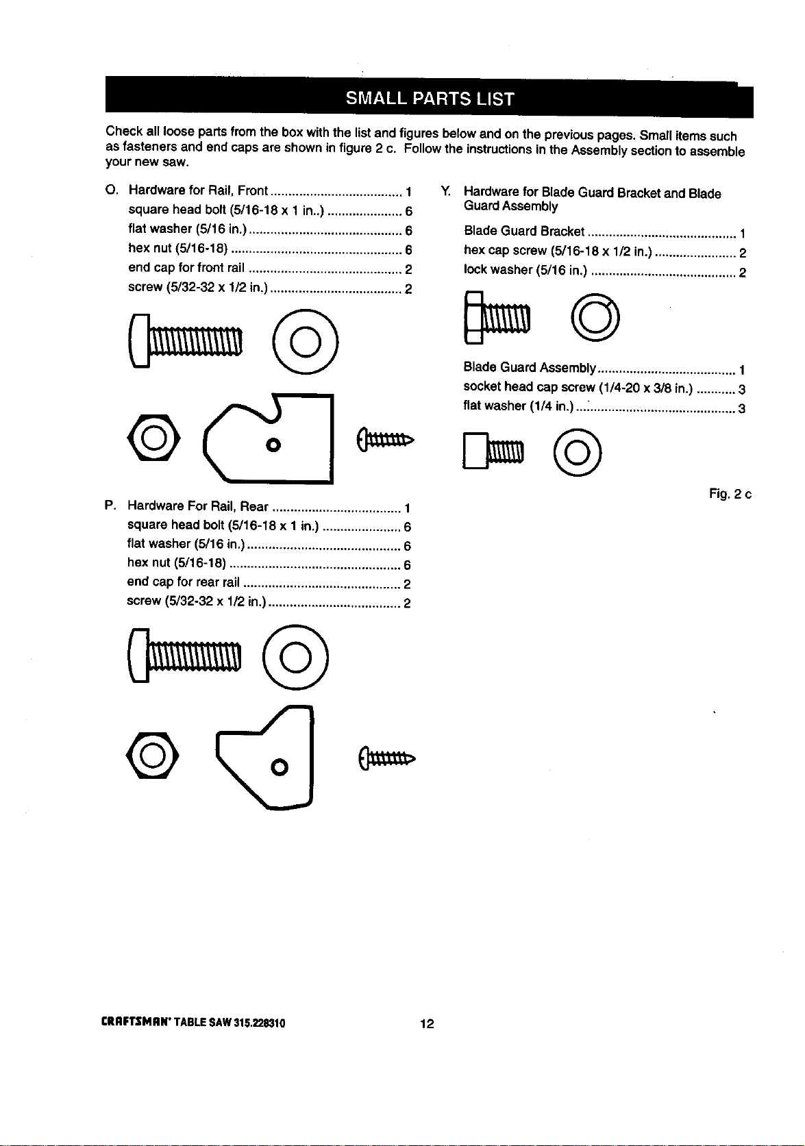
Check all loose partsfrom the box with the listand figuresbelowand on the previouspages, Small itemssuch
as fasteners and end capsare shownin figure2 c. Followthe instructionsin the Assemblysectionto assemble
your new saw.
O. Hardware for Rail, Front..................................... 1
square head bolt (5/16-18 x 1 in..) ..................... 6
flat washer (5/16 in.) ........................................... 6
hex nut (5/16-18) ................................................ 6
end cap for front rail ........................................... 2
screw (5/32-32 x 1/2 in.) ..................................... 2
©
F,
Hardware For Rail, Rear .................................... 1
square head bolt (5/16-18 x 1 in.) ...................... 6
flat washer (5/16 in.) ........................................... 6
hex nut (5/16-18) ................................................ 6
end capfor rear rail ............................................ 2
screw (5/32-32 x 1/2 in.)..................................... 2
Y. Hardware for Blade GuardBracketand Blade
GuardAssembly
BladeGuard Bracket.......................................... 1
hex cap screw (5/16-18 x 1/2 in.)....................... 2
lock washer (5/16 in.) ......................................... 2
Blade Guard Assembly....................................... 1
socket head cap screw (1/4-20 x 3/8 in.) ........... 3
flat washer (1/4 in.) ..._......................................... 3
Fig. 2 c
CRAFTSMAN"TABLESAW315.228310 12
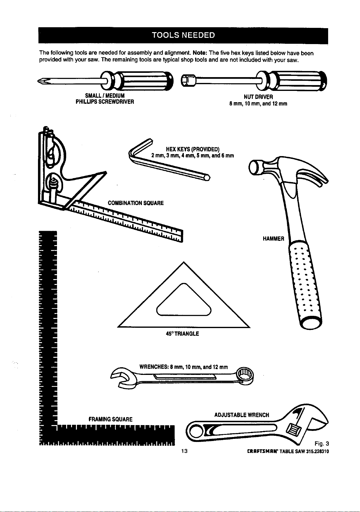
The followingtoolsare neededfor assemblyand alignment. Note: The fivehex keys listedbelow havebeen
providedwith yoursaw.The remainingtoolsare typicalshoptoolsand are notincludedwithyoursaw.
SMALLI MEDIUM
PHILUPSSCREWDRIVER
NUTDRIVER
8 mm,10mm,and12mrn
HEXKEYS(PROVIDED)
and6 mm
COMBINA_ONSOUARE
HAMMER
45°TRIANGLE
WRENCHES:8 mm,10mm,and12mm
FRAMINGSQUARE
ADJUSTABLEWRENCH
13 rRRFTSMRN"TABLESAW315.228310
/
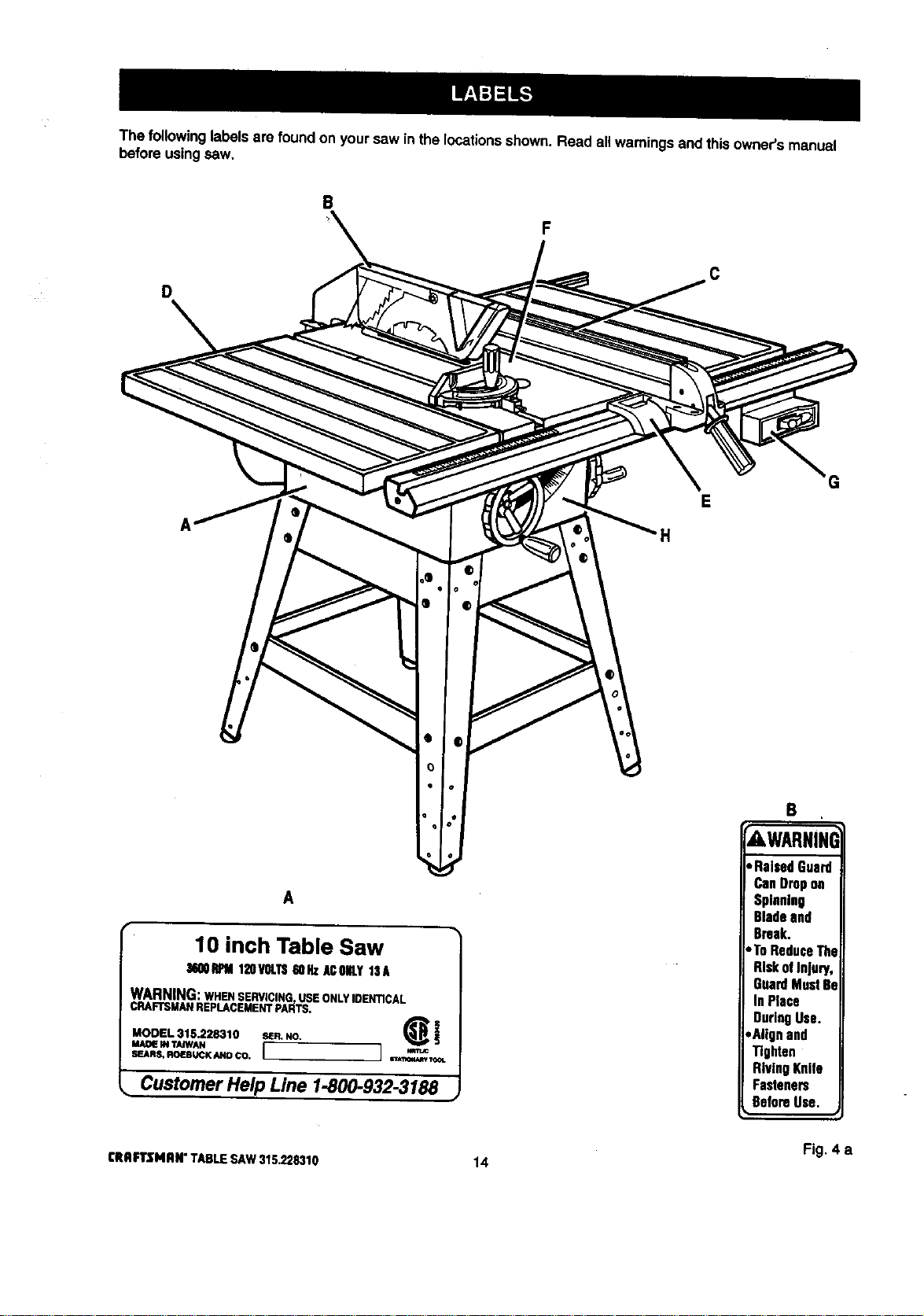
The followinglabelsare found on yoursaw inthe locationsshown. Read allwarningsand thisowner'smanual
before using saw,
B
D
e
o
o
A
10 inch Table Saw
36QOIh_M120VOLTS60HzACONLY13A
WARNING:WHEN SERVICING, USE ONLY IDENTICAL
CRAFTSMANREPLACEMENTPARTS.
MODEL 315.228310 S_R.NO. _i
MAD_ IN TAJWAN
SEARS, ROEBUCK AND CO. i I
sr_l_4_ TOOL
• Customer Help Line 1-800-932-3188 ,
F
H
C
G
B
AWARNINI
• RaisedGuard
CanDropon
Spinning
Bladeand
Break.
•ToReduceThe
RiskofInjury,
GuardMust81
InPlace
DuringUse.
,Alignand
Tighten
RivingKnife
Fasteners
BeforeUse.
Fig, 4 a
CRAFTSMAN"TABLESAW315.228310 14
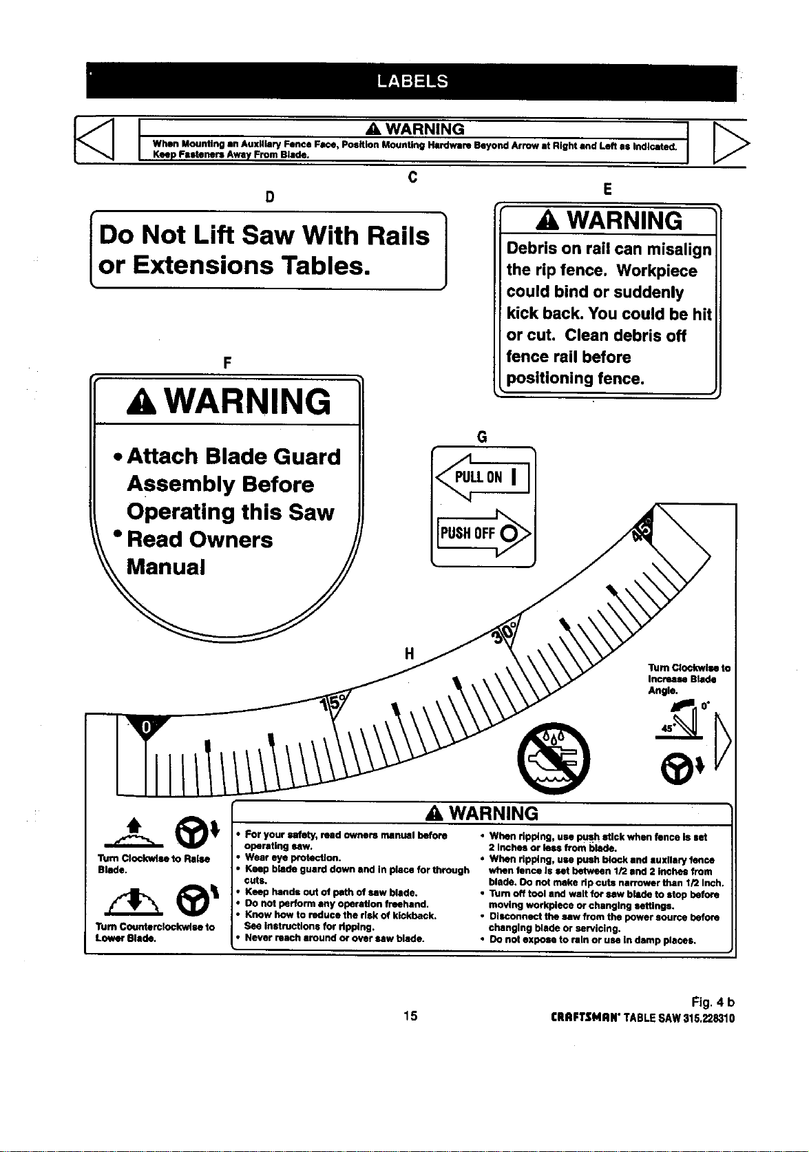
I _ WARNING
When Mounting an Auxiliary Fence Face, Position Mounting Hardware Beyond Arrow at Bight and Left as Indicated.
Keep Fasteners Away From Blade.
C
D E
I ] ,A,WARNING
Do Not Lift Saw With Rails Debris on rail can misalign
Lor Extensions Tables. the rip fence. Workpiece
could bind or suddenly
F
A WARNING
• Attach Blade Guard
Assembly Before
Operating this Saw
• Read Owners
kick back. You could be hit
or cut. Clean debris off
fence rail before
positioning fence.
G
,_LLONI
PUSHOFF
H
®
A WARNING
Turn Clockwise to
Increase Blade
Angle.
Turn Clockwise to Raise
Blade.
"rumCounterclockwise to
Lower Blade.
• For your safety, read owners manual before
operating saw.
• Wear eye p_otection.
• Keep blade guard down and In place for through
cuts.
• Keep hands out of path of saw blade.
• Do not perform any operation freehand.
• Know how to reduce the risk of kickback.
See instructions for ripping.
• Never reach around o¢ over/Niw blade.
• When ripping, use push stick when fence is set
2 Inches or lees from blade.
• When ripping, use push block and auxllary fence
when fence Is set between 1/2 and 2 inches from
blade. Oo nut make rip cuts narrower than 1/2 Inch.
•Tum off tool and walt for saw blade to stop before
moving workplece or changing settings.
• Disconnect the saw from the power source before
changing blade or se_icing.
• Do not expose to rbln or use in damp places.
Fig. 4 b
15 I:RRFTSMIIN"TABLESAW315.228310
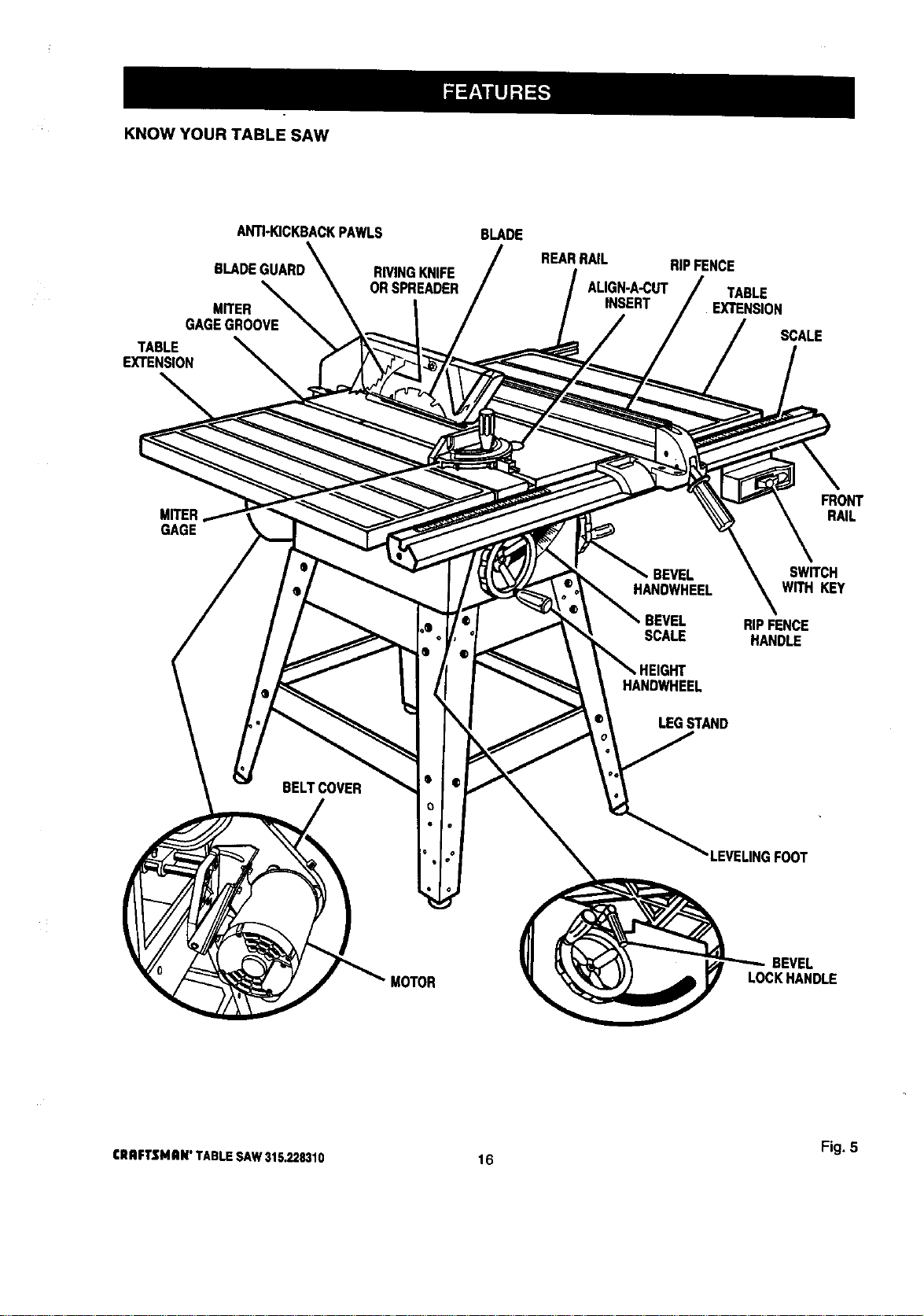
KNOW YOUR TABLE SAW
ANTI-KICKBACKPAWLS
BLADE
MITER
GAGEGROOVE
TABLE
EXTENSION
BLADE
REARRAIL RIPFENCE
RIVINGKNIFE
ORSPREADER ALIGN-A-CUT TABLE
INSERT EXTENSION
SCALE
GAGE
FRONT
RAIL
BELTCOVER
BEVEL SWITCH
HANDWHEEL WITH KEY
RIPFENCE
SCALE HANDLE
HANDWHEEL
LEGSTAND
'LEVELINGFOOT
MOTOR
BEVEL
LOCKHANDLE
Fig. 5
CRAFTSMAN"TABLESAW315.228310 16
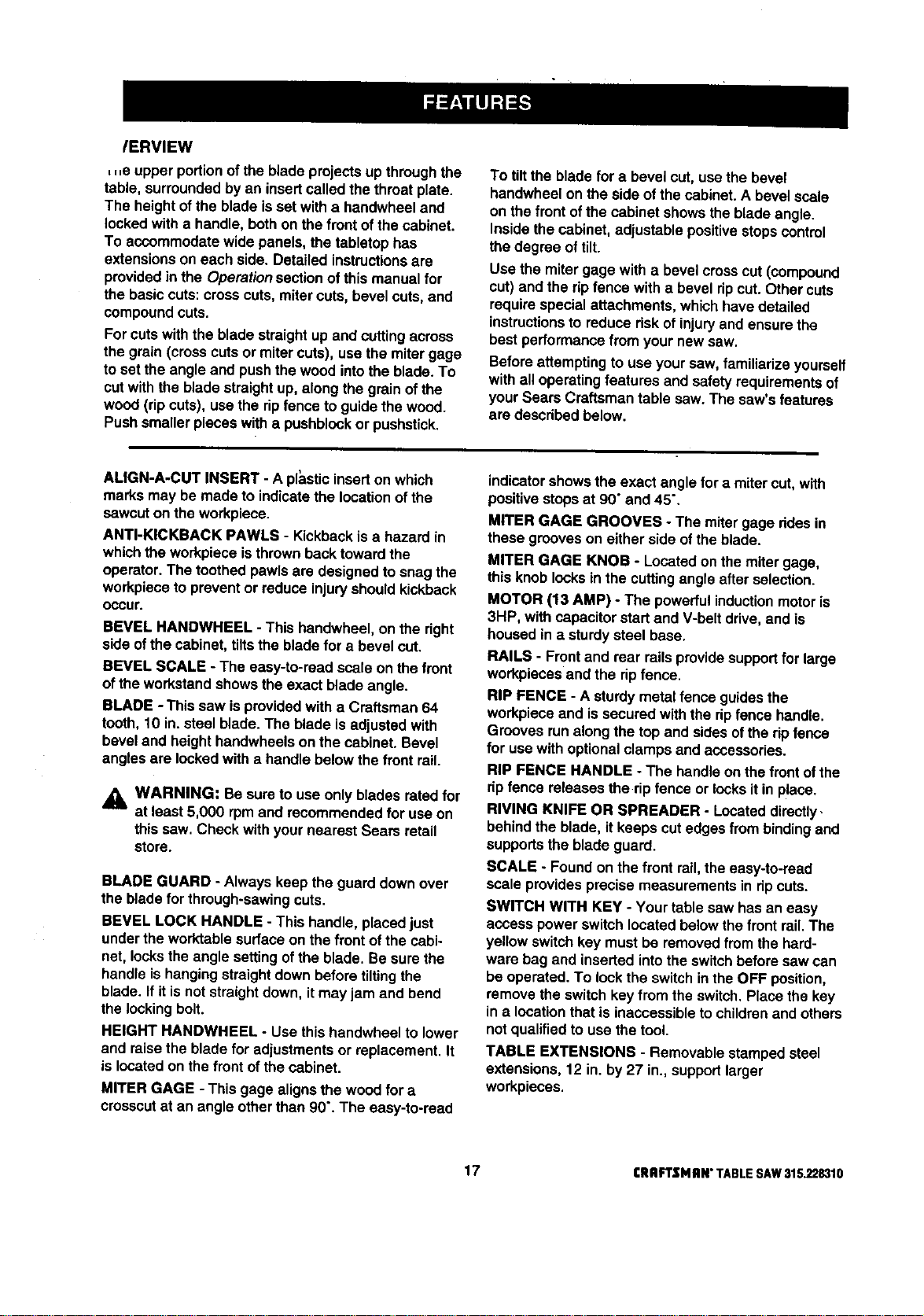
/ERVIEW
,,,e upper portionofthe blade projectsup throughthe
table, surroundedbyan insertcalled thethroat plate.
The height ofthe blade isset witha handwheel and
lockedwith a handle, bothon thefront of the cabinet.
To accommodatewide panels, the tabletop has
extensionson each side. Detailed instructionsare
providedinthe Operationsectionof this manualfor
the basiccuts:crosscuts, mitercuts, bevel cuts,and
compoundcuts.
Forcutswith the blade straightup and cuttingacross
the grain(cross cutsor mitercuts), usethe mitergage
to set the angle and pushthe wood into the blade. To
cut with the blade straight up, along the grain of the
wood (rip cuts), use the rip fence to guide the wood.
Push smallerpieces with a pushblockor pushstick.
To tiltthe blade for a bevel cut, usethe bevel
handwheelon the side ofthe cabinet. A bevel scale
on the front ofthe cabinet showsthe bladeangle.
Insidethe cabinet, adjustablepositivestopscontrol
the degree of tilt.
Use the miter gage with a bevel crosscut (compound
cut)and the ripfence with a bevel ripcut. Other cuts
requirespecialattachments,whichhave detailed
instructions to reduce risk of injury and ensurethe
best performance from your new saw.
Before attemptingto use your saw, familiarize yourself
withall operating features and safety requirements of
your Sears Craftsman table saw. The saw's features
are described below.
ALIGN-A-CUT INSERT - A pt_,sticinsert onwhich
marks may be made to indicate the locationofthe
sawcuton the workpiece.
ANTI-KICKBACK PAWLS - KickbackIs a hazard in
whichthe workpiece isthrownbacktoward the
operator. The toothed pawls are designedto snag the
workpieceto preventor reduceinjuryshouldkickback
Occur.
BEVEL HANDWHEEL - This handwheel, on the right
side ofthe cabinet, tiltsthe bladefor a bevel cut.
BEVEL SCALE - The easy-to-road scale on the front
ofthe work.standshowsthe exact blade angle.
BLADE -This saw is providedwith a Craftsman 64
tooth, 10 in. steel blade. The blade is adjustedwith
bevel and heighthandwheelson the cabinet. Bevel
anglesare lockedwith a handle belowthe front rail.
WARNING: Be sure to use onlyblades rated for
at least 5,000 rpmand recommendedfor useon
this saw. Check with yournearest Sears retail
store.
BLADE GUARD - Always keepthe guard down over
the bladefor through-sawingcuts.
BEVEL LOCK HANDLE - This handle, placedjust
under theworktable surfaceon the frontof the cabi-
net, locksthe anglesettingof theblade. Be surethe
handle ishangingstraightdownbeforetiltingthe
blade. If itis notstraightdown, itmay jam and bend
thelockingbolt.
HEIGHT HANDWHEEL - Use this handwheel to lower
and raise the blade for adjustmentsor replacement.It
is locatedon the front ofthe cabinet.
MITER GAGE - This gage alignsthe wood for a
crosscutat an angle otherthan 90". The easy-to-road
indicator showsthe exact angle for a mitercut, with
positivestopsat 90"and 45".
MITER GAGE GROOVES - The miter gage ddes in
these grooves on eitherside ofthe blade.
MITER GAGE KNOB - Locatedon themiter gage,
this knoblocksin the cuttingangleafter selection.
MOTOR (13 AMP) - The powerfulinductionmotoris
3HP, with capacitorstartand V-belt drive,and is
housedin a sturdysteel base.
RAILS - Front and rear railsprovidesupportfor large
workpiecesend the ripfence.
RiP FENCE - A sturdymetalfence guidesthe
workpieceand issecured withthe ripfence handle.
Grooves runalongthe top and sidesof the ripfence
for usa withoptionalclamps and accessories.
RIP FENCE HANDLE - The handleon the frontofthe
rip fence releasesthe ripfence or locksitin place.
RIVING KNIFE OR SPREADER - Locateddirectly.
behindthe blade, itkeeps cutedges frombindingand
supportsthe blade guard.
SCALE - Foundon the frontrail,the easy-to-road
scale providesprecise measurementsin dp cuts.
SWITCH WITH KEY - Your table saw has an easy
access power switchlocatedbelowthe frontrail.The
yellowswitchkey mustbe removedfromthe hard-
ware bag and inserted intothe switchbefore saw can
be operated. To lockthe switchinthe OFF position,
remove the switch key fromthe switch.Place the key
in a locationthatis inaccessibleto childrenand others
notqualifiedto use the tool.
TABLE EXTENSIONS - Removable stampedsteel
extensions,12 in.by 27 in., supportlarger
workpieces,
17 CRAFTSHAN"TABLESAW315.228310
Assembly isbestdone inthe area where the saw will be used. When you remove the table saw base, loose
parts, and hardware fromthe packingmatedals, check all itemswith the looseparts listand drawing. Ifyou are
unsure about thedescriptionofany part, refer tothe drawing. Ifany parts are missing,delay assemblinguntil
you have obtainedthe missingpart(s).
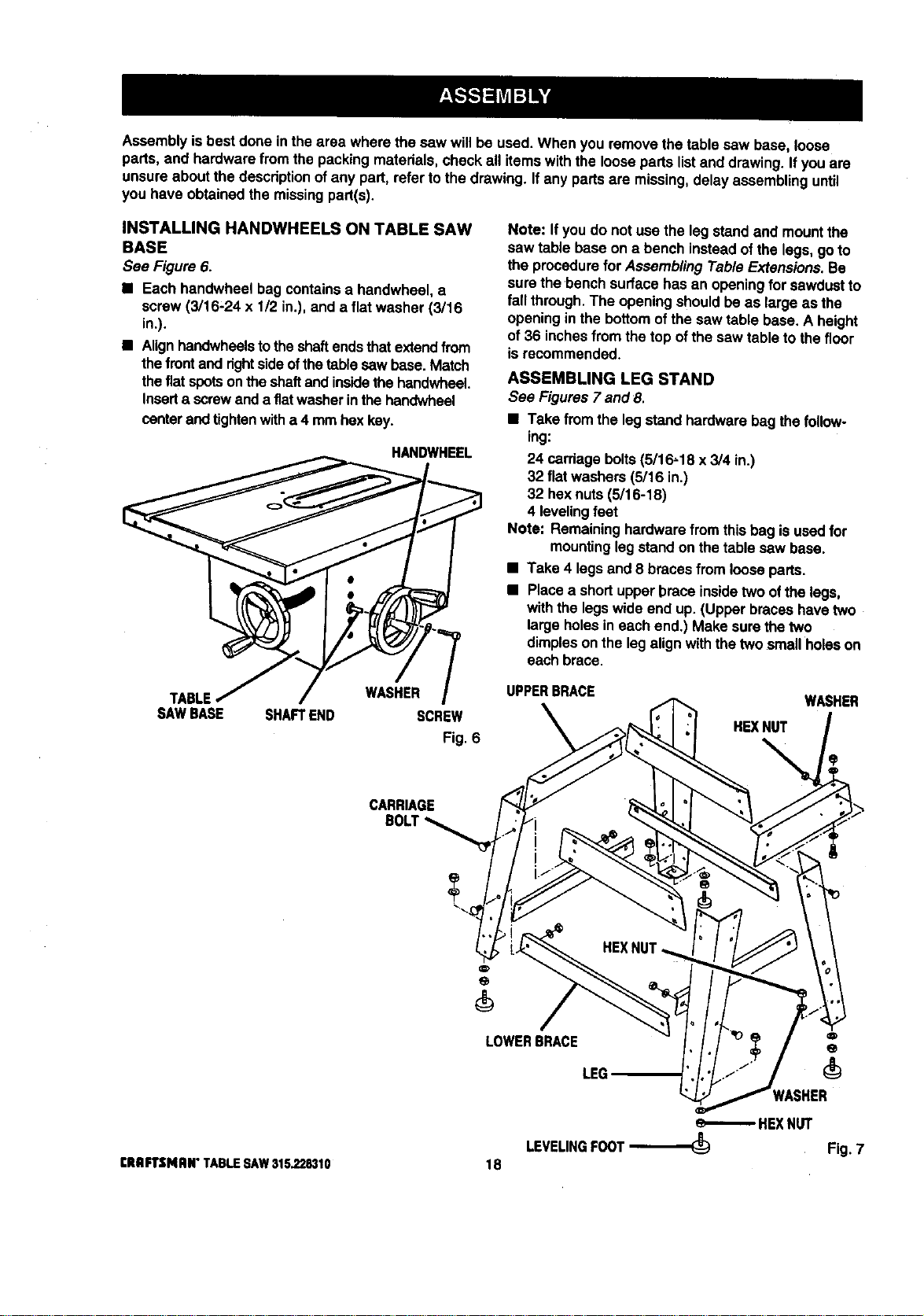
INSTALLING HANDWHEELS ON TABLE SAW
BASE
See Figure 6.
• Each handwheel bag containsa handwheel, a
screw (3/16-24 x 1/2 in.), and a flat washer (3/16
in.).
• Alignhandwheelstotheshaftendsthatextendfrom
thefrontand rightsideofthetable sawbase. Match
thefiatspotsonthe shaftand insidethe handwheeL
Inserta screwand a fiatwasherin thehandwheel
centerandtightenwitha 4 mmhex key.
HANDWHEEL
Note: Ifyou do not usa the leg stand and mountthe
saw table base on a bench insteadofthe legs, goto
the procedurefor Assembling TableExtensions.Be
sure the'bench surfacehas an openingfor sawdustto
fall through.The opening shouldbe as large as the
opening in the bottomofthe saw table base, A height
of 36 inchesfromthe top ofthe saw table to thefloor
is recommended.
ASSEMBLING LEG STAND
See Figures 7 and 8.
• Take fromthe legstand hardware bag thefollow-
ing:
24 carriagebolts(5/16,18 x 3/4 in.)
32 flatwashers (5/16 in.)
32 hex nuts(5/16-18)
4 levelingfeet
Note: Remaininghardwarefrom thisbag is usedfor
mountingleg standon the table saw base.
• Take 4 legs and 8 bracesfrom looseparts.
• Place a shortupper brace insidetwo ofthe legs,
withthe legswide end up.(Upper braceshavetwo
largeholesin each end.) Make sure thetwo
dimplesonthe leg alignwith thetwosmall holeson
each brace.
TABLE WASHER
SAWBASE SHAFTEND SCREW
Fig. 6
UPPERBRACE
HEXNUT
%
WASHER
CARRIAGE
LOWERBRACE
LEG
[RRFTSMIIN" TABLESAW315,228310
HEXNUT
LEVELINGFOOT_ Fig. 7
18
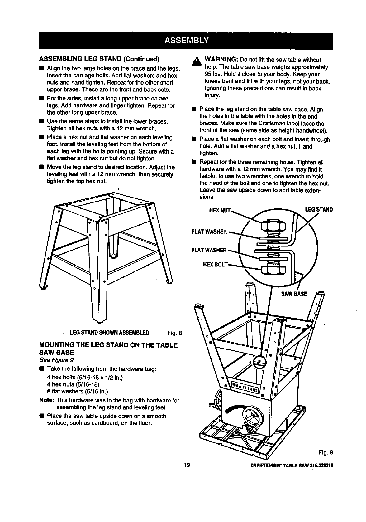
ASSEMBLINGLEGSTAND(Continued)
• Alignthetwo largeholeson the brace and the legs.
Insertthe cardage bolts.Addflatwashersand hex
nuts and handtighten. Repeat forthe othershort
upper brace. These are thefrontand backsets.
• For the sides,installa long upperbrace on two
legs.Add hardware and fingertighten.Repeat for
the otherlong upperbrace.
• Use the same stepsto installthe lowerbraces.
Tightenall hex nutswith a 12 mm wrench.
• Place a hex nut and flatwasher on each leveling
foot.installthe levelingfeet fromthe bottomof
each legwith the boltspointingup.Secure witha
fiatwasher and hex nutbut do nottighten.
• Move the leg standto desiredlocation.Adjustthe
levelingfeet witha 12 mmwrench, then securely
tightenthe top hexnut.
_k WARNING: Do notliftthe saw table without
help. The table saw baseweighs approximately
95 Ibs.Hold itcloseto yourbody. Keep your
kneesbent and liftwith yourlegs, notyourback.
Ignoringthese precautionscan resultin back
injury.
• Place the legstand on the table saw base. Align
the holesinthe tablewith theholesin theend
braces.Make surethe Craftsmanlabelfaces the
front ofthesaw (same sideas heighthandwheel).
• Place aflat washeron each boltand insertthrough
hole. Adda flat washerand a hex nut.Hand
tighten.
• Repeat for thethree remainingholes.Tightenall
hardwarewith a 12 mmwrench. You may find it
helpfulto usetwo wrenches,one wrenchtohold
the head ofthe boltand one to tightenthe hex nut.
Leavethe saw upsidedownto add table exten-
sions.
HEXI, LEGSTAND
LEGSTANDSHOWNASSEMBLED Fig. 8
MOUNTING THE LEG STAND ON THE TABLE
SAW BASE
See Figure 9.
• Take thefollowingfrom the hardwarebag:
4 hex bolts(5/16-18 x 1/2 in.)
4 hex nuts (5/18-18)
8 flatwashers (5/16 in.)
Note: This hardwarewas inthe bagwith hardwarefor
assemblingthe leg stand and levelingfeet.
• Place the saw table upsidedownon a smooth
surface,such as cardboard, on thefloor.
Fig. 9
19 CRAFTSMRN"TABLESAW315.228310
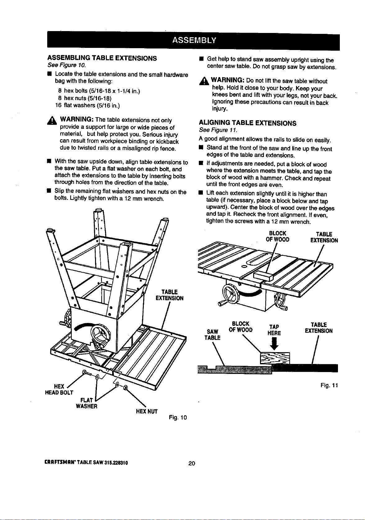
ASSEMBLING TABLE EXTENSIONS
See Figure 10.
• Locate thetable extensionsand the smal_hardware
bag withthe following:
8 hex bolts(5/16-18 x 1-1/4 in.)
8 hex nuts (5/16-18)
16 fiatwashers (5/16 in.)
,_ WARNING: The table extensions notonly
providea supportfor large or wide pieces of
material, but help protectyou.Serious injury
can result from workpiece bindingor kickback
due to twisted rails or a misaligned rip fence.
• With the saw upsidedown, align table extensionsto
the sawtable. Puta flat washer on each bolt,and
attachthe extensionsto thetable byinsertingbolts
throughholes from thedirectionofthe table.
• Slipthe remaining flat w_shers and hex nuts on the
bolts. Lightly tighten with a 12 mm wrench.
• Get helpto standsaw assemblyupdghtusingthe
centersaw table. Do notgraspsaw by extensions.
_i, WARNING: Do not lift the saw table without
help. Hold it closeto yourbody. Keep your
kneesbent and liftwithyourlegs, not your back.
Ignoringthese precautionscan resultin back
injury.
ALIGNING TABLE EXTENSIONS
See Figure 11.
A good alignmentallowsthe railsto slideon easily.
• Stand at the frontofthe saw and lineup the front
edgesof thetable and extensions.
• ifadjustmentsare needed, puta blockof wood
wherethe extensionmeetsthe table, and tapthe
blockofwoodwith a hammer.Check and repeat
untilthe frontedges are even.
• Lifteach extensionslightlyuntilitis higherthan
table (if necessary,placea blockbelowand tap
upward).Center the blockofwoodoverthe edges
and tapit. Recheckthe front alignment.Ifeven,
tightenthe screwswith a 12 mm wrer,_h.
BLOCK TABLE
OFWOOD EXTENSION
TABLE
EXTENSION
SAW
TABLE
BLOCK TAP TABLE
OFWOOD HERE EXTENSION
HEX
HEAD BOLT
FLA;
WASHER
HE](NUT
Fig. 10
Fig. 11
eRRFTSMRI_ TABLESAW3152.28310 20
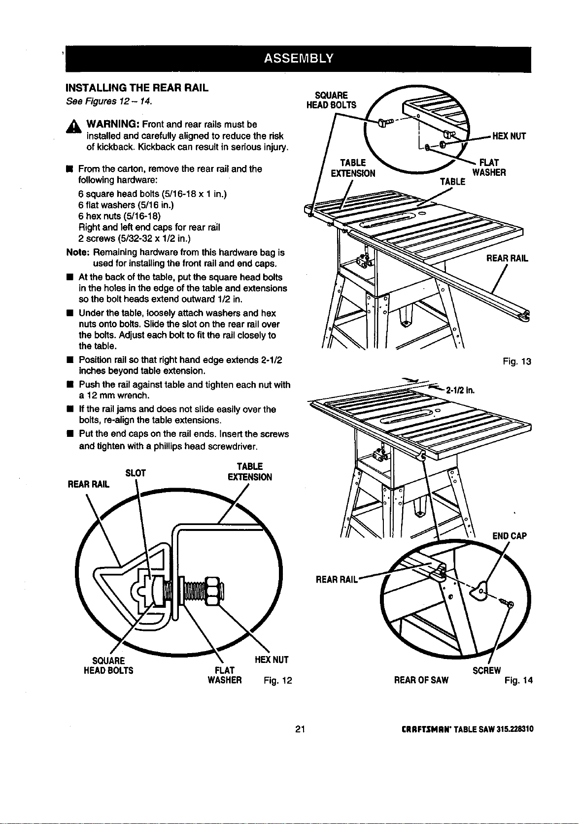
INSTALLING THE REAR RAIL
See Figures 12- 14.
,_ WARNING: Frontand rear railsmustbe
installedand carefullyalignedto reducethe risk
of kickback. Kickbackcan resultin seriousinjury.
• Fromthe carton,remove the rear rail and the
followinghardware:
6 squarehead bolts(5/16-18 x 1 in.)
6 flatwashers (5/16 in.)
6 hex nuts(5/16-18)
Right and leftend capsfor rear rail
2 screws(5/32-32 x 1/2 in.)
Note: Remaininghardware from this hardware bag is
used for installingthe front railand end caps.
• At theback ofthetable, put the squarehead bolts
inthe holesin theedge of the table and extensions
so the boltheadsextend outward 1/2 in.
• Underthe table, looselyattachwashers and hex
nutsontobolts.Slidethe sloton the rear railover
the bolts.Adjusteach boltto fit the railcloselyto
the table.
• Positionrailsothatrighthandedge extends 2-1/2
inchesbeyondtable extension.
• Pushthe railagainsttable and tighteneach nutwith
a 12 mm wrench.
• Ifthe railjamsand does notslideeasily over the
bolts,re-alignthe table extensions.
• Putthe end caps onthe railends. Insertthe screws
and tightenwitha phillipshead screwdriver.
SLOT
REARRAIL
TABLE
EXTENSION
SQUARE HEXNUT
HEADBOLTS FLAT
WASHER Fig. 12
SQUARE
HEADBOLTS
TABLE
FLAT
WASHER
SCREW
NUT
REARRAIL
Fig. 13
ENDCAP
REAROF SAW Fig. 14
21 CRRFTSNAN" TABLE SAW 315.228310
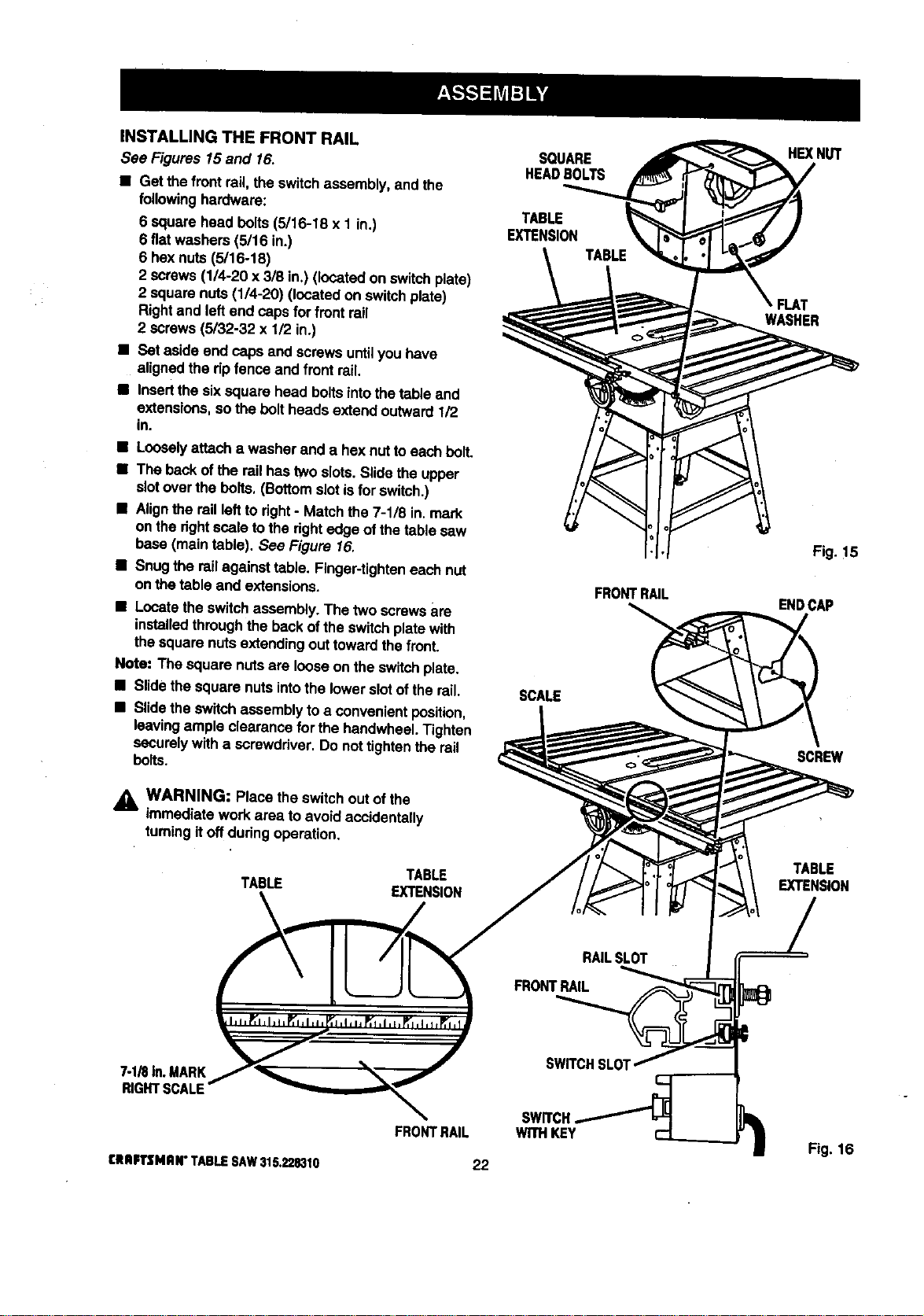
INSTALLING THE FRONT RAIL
See Figures 15and 16.
• Get the frontrail the switchassembly, and the
followinghardware:
6 squarehead botts(5/16-18 x 1 in.)
6 fiatwashers (5/16 in.)
6 hex nuts (5/16-18)
2 screws(1/4-20 x 3/8 in.) (locatedon switch plate)
2 squarenuts (1/4-20) (located on switchplate)
Rightand leftend capsfor front rail
2 screws(5/32-32 x 1/2 in.)
• Set aside end capsand screwsuntilyou have
alignedthe dp fence and front rail.
• Insertthe sixsquare head boltsintothe table and
extensions,sothe boltheads extend outward 112
in.
• Looselyattacha washer and a hex nut toeach bolt.
• The backofthe rail hastwo slots.Slidethe upper
slotover the bolts. (Bottomslotisfor switch.)
• Alignthe railleft to fight- Matchthe 7-1/8 in. mark
on the dghtscale tothe dghtedge ofthe table saw
base (main table). See Figure 16.
• Snugthe railagainsttable. Finger-tighteneach nut
onthetable and extensions.
• Locatethe switchassembly.The two screws are
installedthroughthe backofthe switchplate with
thesquarenuts extendingout towardthefront.
Note: The square nutsare looseon the switchplate.
• Slidethesquare nuts intothe lowerslotof therail.
• Slidetheswitchassembly toa convenientposition,
leavingample clearancefor the haedwheeLTighten
securelywitha screwdriver. Do nottightenthe rail
bolts.
A_ WARNING: Place the switchout ofthe
immediatework area to avoidaccidentally
turningitoffdudng operation.
TABLE
TABLE
EXTENSION
SOUARE
HEADBOLTS
TABLE
EXTENSION
SCALE
FRONTRAIL
HEXNUT
FLAT
WASHER
Fig.!5
ENDCAP
SCREW
TABLE
EXTENSION
_IRIn.MARK
R_HTBCALE
SWITCH.
WITHKEY
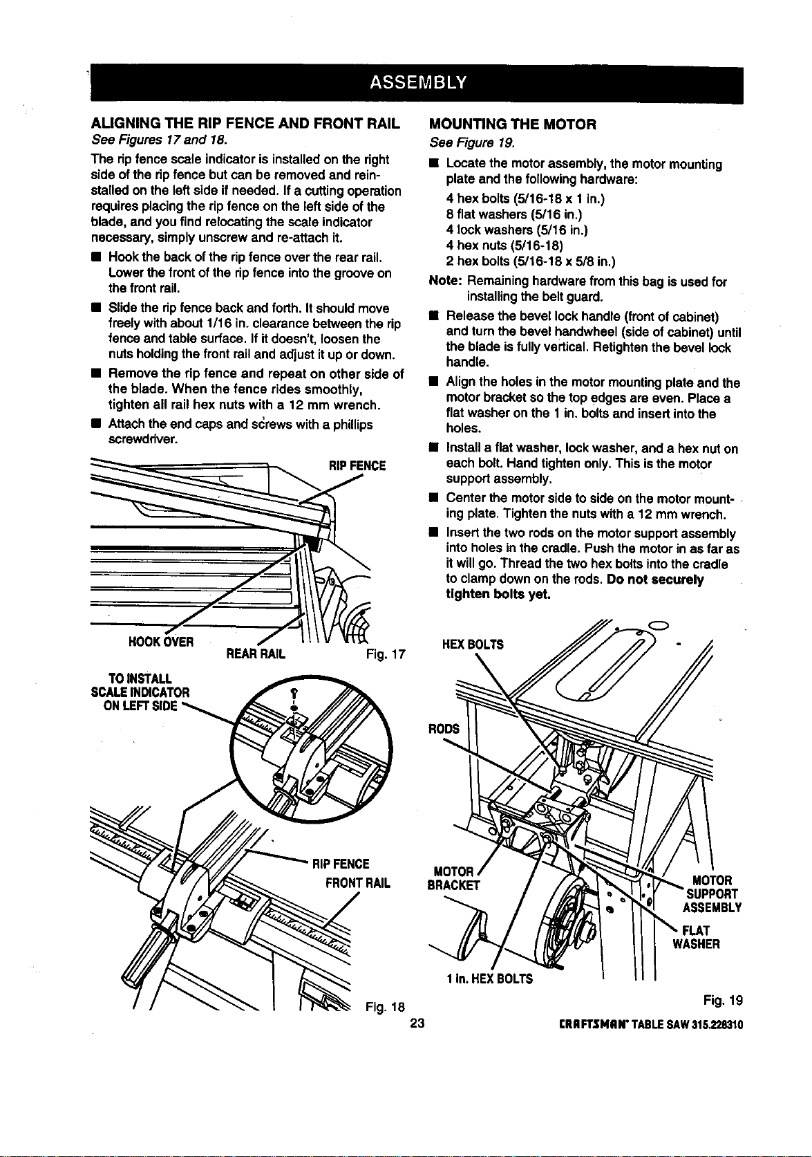
ALIGNINGTHERIPFENCEANDFRONTRAIL
See Figures 17and 18.
The ripfence scale indicatoris installedon the right
side ofthe ripfence but can be removedand rein-
stalledon the left side if needed. If a cuttingoperation
requiresplacingthe ripfence on the left side ofthe
blade, and you find relocatingthe scale indicator
necessary,simplyunscrewand re-attach it.
• Hookthe backof the ripfenceover the rear rail.
Lowerthe frontof theripfence intothe grooveon
thefrontrail.
• Slidethe ripfence backand forth. Itshouldmove
freely withabout 1/16 in.clearance between the rip
fence and table surface.If itdoesn't, loosenthe
nuts holdingthe frontrail and adjust itup or down.
• Remove the rip fence and repeat on other side of
the blade. When the fence rides smoothly,
tighten all rail hex nuts with a 12 mm wrench.
• Attachthe end capsand s_rewswitha phillips
screwdriver.
NCE
oo
REARRAIL Fig. 17
TOINSTALL
SCALEINDICATOR
ONLEFT
MOUNTING THE MOTOR
See Figure 19.
• Locate the motorassembly,the motormounting
plate and the followinghardware:
4 hex bolts(5/16-18 x 1 in.)
8 flat washers (5/16 in,)
4 lockwashers (5/16 in.)
4 hex nuts(5/16-18)
2 hex bolts(5/16-18 x 5/8 in.)
Note: Remaininghardwarefromthis bag isused for
installingthe belt guard.
• Release the bevel lock handle (frontof cabinet)
and turnthe bevel handwheel (sideof cabinet) until
the blade isfullyvertical. Retightenthe bevel lock
handle.
• Alignthe holes inthe motormountingplate and the
motorbracketso thetop edges are even. Placea
flat washer on the 1 in. boltsand insertintothe
holes.
• Installa flatwasher, lockwasher, and a hexnut on
each belt. Hand tightenonly.This isthe motor
supportassembly.
• Center the motorside to side on themotormount-
ingplate.Tighten the nutswitha 12 mm wrench.
• Insertthe two rodson the motorsupportassembly
intoholesin the cradle. Pushthe motorin as far as
itwillgo. Thread the two hexboltsintothe cradle
to clamp downon the rods. Do not securely
tighten bolts yet.
HEXBOLTS
RODS
RIPFENCE
FRONTRAIL
MOTOR
BRACKET
MOTOR
ASSEMBLY
1 In.HEXBOLTS
WASHER
Fig. 18 Fig. 19
23 CRRFTSNRN"TABLESAW315.228310
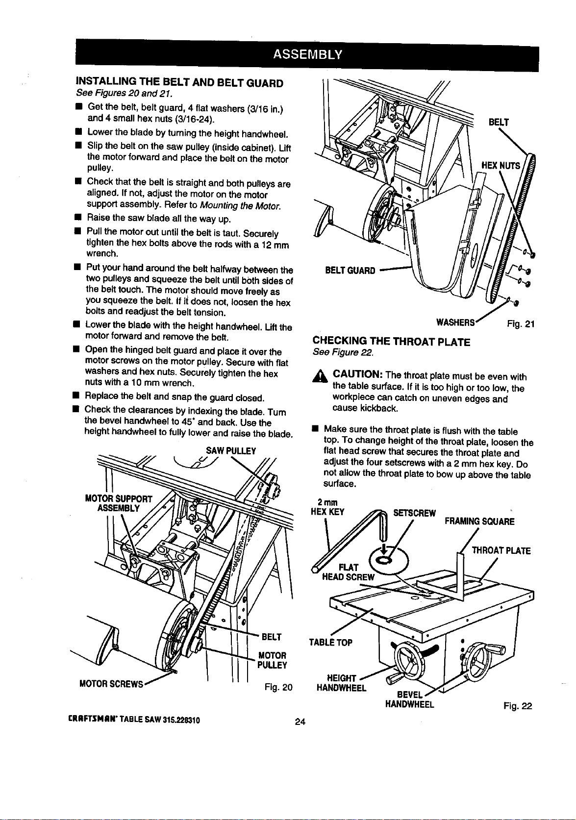
INSTALLINGTHEBELTANDBELTGUARD
See Figures20 and 21.
• Get the belt,belt guard, 4 flatwashers(3/16 in.)
and 4 smallhex nuts (3/16-24).
• Lowerthe bladeby turningthe heighthandwheel.
• Slipthe belton the saw pulley(insidecabinet). Lift
the motorforwardand place thebelt on the motor
pulley.
• Check thatthe belt is straightand bothpulleysare
aSgned. If not, adjustthe motoron the motor
supportassembly. Refer to MountingtheMotor.
• Raise the saw blade all theway up.
• Pullthe motorout untilthebelt istaut. Securely
tightenthe hex boltsabove therodswitha 12 mm
wrench.
• Putyourhandaroundthe belthalfwaybetween the
two pulleysand squeeze the be_tuntil bothsidesof
the belt touch.The motorshouldmove freelyas
you squeeze the belt. If i_does not,loosenthe hex
boltsand readjustthe belttension.
• Lowerthe bladewith the heighthandwheel.Liftthe
motorforwardand remove the belt.
• Open the hingedbelt guard and place itover the
motorscrewson the motorpulley.Secure withfiat
washers and hex nuts.Securelytightenthe hex
nuts witha 10 mm wrench.
• Replace the belt and snap the guardclosed.
• Checkthe clearances byindexingthe blade.Turn
the bevel hendwheelto 45" and back. Usethe
heighthandwheelto fully lowerand raise theblade.
SAWPULLEY
MOTORSUPPORT
ASSEMBLY
MOTORSCREWS
rRRFTSMRN"TABLESAW315,228310
BELT
BELTI
MOTOR
Fig. 20
24
CHECKING THE THROAT PLATE
See Figure22.
Fig. 21
j_ CAUTION: The throatplate mustbe even with
the table surface. If itistoo highor too low,the
workpiece can catchon unevenedges and
cause kickback.
• Make surethe throatplate isflush withthe table
top.To change heightofthethroatplate,loosenthe
flathead screwthatsecuresthethroatplate and
adjustthe four setscrewswitha 2 mm hex key. Do
not allow the throatplate to bow up above the table
surface.
2mm
HEXKEY SETSCREW
FRAMINGSQUARE
IROATPLATE
TABLETOP
HEIGHT
HANDWHEEL
BEVEL
HANDWHEEL
Fig. 22
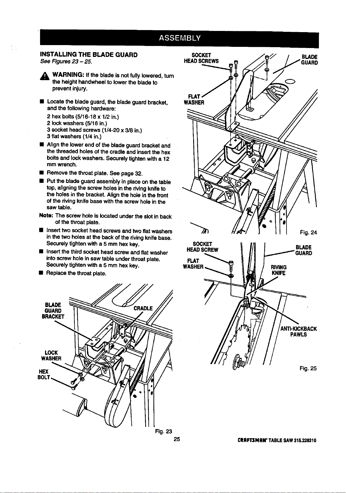
INSTALLING THE BLADE GUARD
See Figures23 - 25.
WARNING: Ifthe blade isnot fully lowered,tum
the heighthandwheel to lowertheblade to
preventinjury.
• Locatethe blade guard,the blade guardbracket,
and the followinghardware:
2 hex bolts(5/16-18 x 1/2 in.)
2 lockwashers (5/16 in.)
3 sockethead screws(1/4-20 x 3/8 in.)
3 fiatwashers (1/4 in.)
• Alignthe lowerend of the bladeguard bracketand
the threaded holesof thecradle and insertthe hex
boltsand _ockwashers.Securelytk3htanwith a 12
mm wrench.
• Remove thethroat plate. See page 32.
• Putthe bladeguard assemblyin place on thetable
top,aligningthe screwholes inthe rivingknifeto
the holesin thebracket.Alignthe holeinthe front
of the rivingknifebase withthe screwholein the
saw table.
Note: The screwhole islocatedundertheslot in back
ofthe throatplate.
• Inserttwo sockethead screws and twoflatwashers
inthe two holesat the beckofthe dyingknifebase.
Securelytightenwith a 5 mm hex key.
• Insertthe thirdsockethead screwand flat washer
intoscrewholein saw table underthroatplate.
Securelytightenwith a 5 mm hex key.
• Replacethe throatplate.
SOCKET
HEADSCREWS
FLM
WASHER
SOCKET
HEADSCREW
FLAT
RIVING
KNIFE
BLADE
Fig. 24
BLADE
BLADE
GUARD
BRACKET
_NTI-KICKBACK
PAWLS
LOCK
WASHER
HEX
Fig. 25
Fig. 23
25 CRRFTSNnN"TABLESAW315.228310
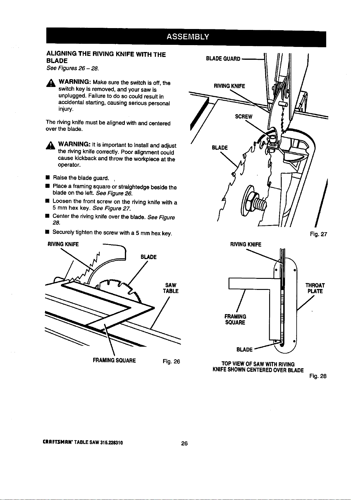
ALIGNINGTHERIVINGKNIFEWITHTHE
BLADE
See Figures26 - 28.
_l, WARNING: Make sure the switchisoff, the
switchkey is removed, and yoursaw is
unplugged.Failure todo socould resultin
accidental starting, causing serious personal
injury.
The rivingknife must be alignedwithend centered
overthe blade.
_I, WARNING: It isimportantto installand adjust
the rivingknifecorrectly.Pooralignmentcould
cause kLckbackand throwthe workpiece at the
operator.
• Raisethe blade guard.
• Placea framing squareor straightedgebesidethe
bladeon the left. See Figure26.
• Loosen the front screw on the rivingknife with a
5 mm hex key. See Figure 27.
• Center the rivingknifeover the blade. See Figure
28.
• Securelytightenthe screwwitha 5 mm hex key.
RMNGKNIFE
BLADE
SAW
TABLE
FRAMINGSQUARE Fig. 26
BLADEGUARD
RIVINGKNIFE
BLADE
/
Fig. 27
RIVINGKNIFE
I
/
FRAMING
SQUARE
BLADE
_ROAT
PLA_
/
TOPVIEWOFSAWWITHRIVING
KNIFESHOWNCENTEREDOVERBLADE
Fig. 28
rRIIfTSMRN" TABLESAY/315.22S310 26
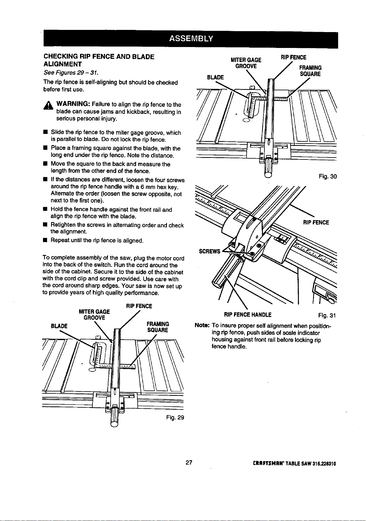
CHECKING RIP FENCE AND BLADE
ALIGNMENT
See Figures29 - 31.
The ripfence is self-aligningbut shouldbe checked
before first use.
_, WARNING: Failure to align the ripfence tothe
blade can causejams and kickback,resultingin
seriouspersonal injury.
• Slidethe ripfence tothe mitergage groove,which
isparallelto blade. Do not lockthe ripfence.
• Place a framing square againstthe blade,with the
longend underthe ripfence. Note the distance.
• Movethe square tothe back and measure the
lengthfrom theother end ofthe fence.
• Ifthe distancesare different,loosenthefour screws
aroundthe ripfence handlewith a 6 mm hex key.
Alternatethe order (loosenthe screwopposite,not
nexttothe first one).
• Holdthe fence handle againstthefrontrailand
alignthe ripfence withthe blade.
• Retightenthe screwsin alternatingorderand check
thealignment.
• Repeat untilthe ripfence is aligned.
To completeassemblyof the saw, plug the motorcord
intothe backof the switch.Run the cordaroundthe
side ofthe cabinet. Secure itto the side of the cabinet
withthe cordclipand screwprovided. Use care with
thecord aroundsharpedges. Yoursaw isnow set up
toprovideyears of highquality performance.
BLADE
MITERGAGE
GROOVE
RIPFENCE
FRAMING
SQUARE
€
BLADE
MITERGAGE
GROOVE
RIPFENCE
FRAMING
SOUARE
Fig. 30
RIP FENCE
RIPFENCEHANDLE Fig. 31
Note: To insureproperselfalignmentwhen positiOn-
ingripfence, pushsidesofscale indicator
housingagainstfront railbeforelookingrip
fence handle.
Fig. 29
27 CRaFTSMRN"TABLESAW315.228310
To avoid unnecessarysetupsand adjustments,a
goodpracticeisto check yoursetupscarefullywith a
framing squareand make practicecuts in scrapwood
beforemakingfinish cutsin goodworkpieces.Do not
startany adjustmentsuntilyou have checkedw_tha
squareand made test cutsto be sure adjustmentsare
needed.
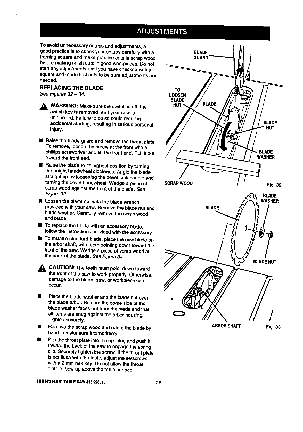
REPLACING THE BLADE
See Figures32 - 34.
_1, WARNING: Make sure the switchis off,the
switchkey is removed, and yoursaw is
unplugged.Failureto do socould resultin
accidentalstarting,resultinginseriouspersonal
injury.
T0
LOOSEN
BLADE
BLADE
GUARD
BLADE
• Raise the bladeguard and remove the throatplate.
TOremove, loosenthe screwat the frontwitha
phillipsscrewddver and I!ftthe front end. Pullitout
towardthe front end.
• Raise the blade to itshighestpositionby turning
the height handwheelclockwise.Angle the blade
straightup bylooseningthe bevel lockhandle and
turningthe bevel handwheet.Wedge a piece of
scrapwood againstthe frontof the blade. See
Figure32.
• Loosenthe blade nut withthe bible wrench
providedwithyour saw. Remove the bladenut and
bladewasher. Carefullyremove the scrap wood
and blade.
• To replacethe bladewith an accessoryblade,
follow the instructionsprovidedwiththeaccessory.
• To install a standard blade, place the newblade on
thearbor shaft,withteeth pointing downtowardthe
front of thesaw, Wedge a piece ofscrap woodat
the backofthe blade. See Figure34.
CAUTION: The teeth mustpointdowntoward
thefrontofthe saw towork properly.Otherwise,
damage to the blade, saw, or workpiececan
occur.
SCRAPWOOD
BLADE
I
/
I
BLADE
WASHER
BLADEHUT
• Place the bladewasher and the blade nut over
the bladearbor. Be sure thedome side ofthe
bladewasher faces out from the bladeand that
all itemsare snugagainstthe arbor housing.
Tightensecurely.
• Remove the scrapwood and rotate theblade by
handto make sure itturnsfreely.
• Slipthethroat plate intothe openingand pushit
towardtheback of thesaw to engage the spring
clip,Securelytightenthe screw. If thethroatplate
isnotflush with the table,adjustthe setscrews
with a 2 mrn hex key.[3onot allow the throat
plateto bow up above thetable surface.
ARBORSHAFT
/
Fig. 33
[RRFTSMRW TABLESAW$15.2283t0 28
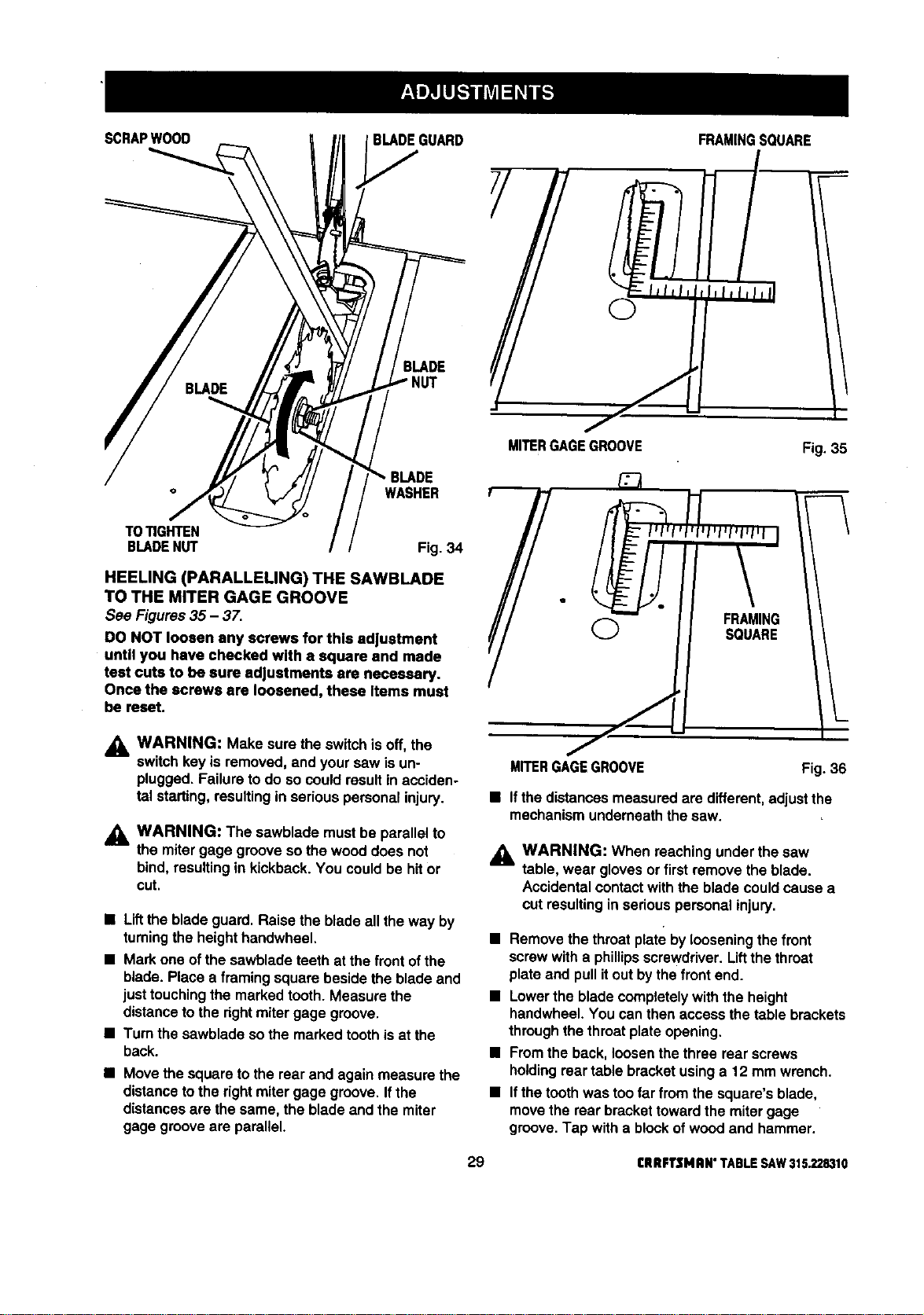
SCRAPWOOD
BLADEGUARD
BLADE
NUT
WASHER
TOTIGHTEN
BLADENUT Fig. 34
HEELING (PARALLELING) THE SAWBLADE
TO THE MITER GAGE GROOVE
See Figures 35 - 37.
DO NOT loosen any screws for this adjustment
until you have checked with a square and made
test cuts to be sure adjustments are necessary.
Once the screws are loosened, these Items must
be reset.
_k WARNING: Make sure the switchisoff, the
switchkey is removed, and your saw is un-
plugged.Failureto do so couldresultin acciden-
tal starting,resultingin seriouspersonalinjury.
_l, WARNING: The sawblade mustbe parallelto
the mitergage groove sothe wooddoes not
bind,resultingin kickback.You couldbe hitor
cut.
• Liftthe blade guard.Raise the blade all theway by
turning the height handwheel.
• Mark one of the sawbladeteeth at the front of the
blade. Place a framing square beside the blade and
just touching the marked tooth. Measure the
distance to the right miter gage groove.
• Turn the sawblade so the marked tooth is at the
back.
• Move the squareto the rear and again measure the
distanceto the rightmitergage groove. Ifthe
distancesare the same, the blade and the miter
gage groove are parallel.
/
MITERGAGEGROOVE
FRAMINGSQUARE
Fig. 35
(_ FRAMING
SQUARE
f
MITERGAGEGROOVE
Fig. 36
• Ifthe distancesmeasuredare different,adjustthe
mechanismunderneaththesaw.
j_ WARNING: When reachingunder the saw
table, wear glovesor firstremove the blade.
Accidentalcontactwith the blade couldcause a
cut resultingin seriouspersonalinjury.
• Remove thethroatplate by loosening the front
screwwitha phillips screwdriver.Liftthe throat
plateand pull itout by the front end.
• Lowerthe blade completelywiththe height
handwheel.You can then access thetable brackets
throughthethroatplate opening.
• Fromthe back, loosenthethree rear screws
holdingreartable bracketusinga 12 mm wrench.
• Ifthe toothwas too far from the square'sblade,
movethe rear brackettowardthe mitergage
groove.Tap with a blockofwoodand hammer.
29 CRRFTSNRN"TABLESAW315.228310
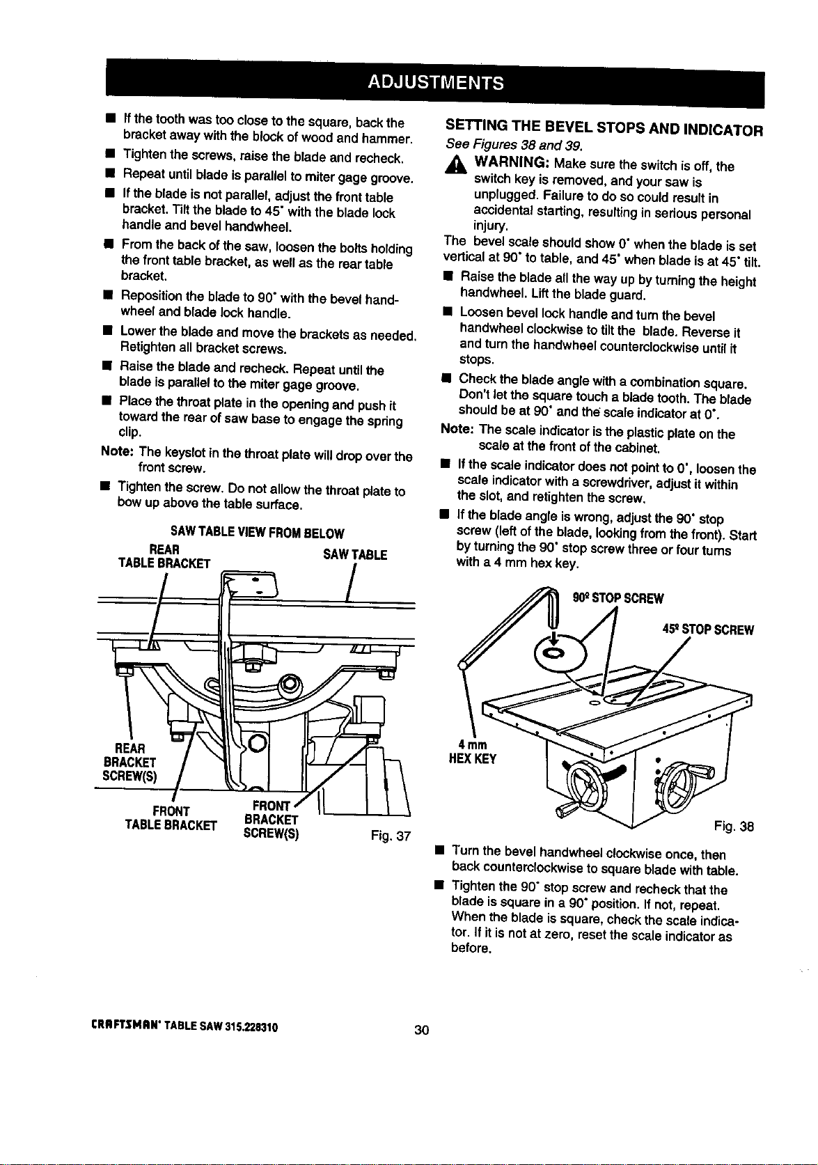
• Ifthetoothwas too close tothe square, backthe
bracket away withthe blockofwoodand hammer.
• Tightenthe screws,raise the blade and recheck.
• Repeat untilblade isparallelto mitergage groove.
• Ifthe blade Is not parattel,adjustthe fronttable
bracket.Tiltthe blade to45"with the bladelock
handleand bevel handwheel.
• Fromthe backofthe saw, toosenthe bolts holding
the front table bracket,as well as the reartable
bracket.
• Repositionthe bladeto 90"with the bevel hand-
wheel and blade lock handle.
• Lowertheblade and movethe bracketsas needed.
Retightenall bracket screws.
• Raise the bladeand recheck. Repeat untilthe
bladeis parallelto the miter gage groove.
• Place thethroatplate in the openingand pushit
towardthe rearof saw baseto engage the spring
clip.
Note: The keyslotin thethroatplate willdrop overthe
frontscrew.
• Tightenthe screw. Do not allow the throatplateto
bow up above thetable surface.
SAWTABLEVIEWFROMBELOW
REAR SAWTABLE
TABLEBRACKET /
SETTING THE BEVEL STOPS AND INDICATOR
See Figures38 and 39.
,_ WARNING: Make sure theswitchis off, the
switchkey isremoved, and yoursaw is
unplugged.Failureto do socould resultin
accidentalstarting,resultingin serious personal
injury.
The bevel scale shouldshow 0"whenthe blade isset
verticalat 90"totable, and 45" when blade isat 45" tilt.
• Raise the blade all the way up by turningthe height
handwheel. Liftthe bladeguard.
• Loosenbevel lookhandleand turnthe bevel
handwheelclockwisetotiltthe blade, Reverse it
and turnthe handwheelcounterclockwiseuntilit
stops.
• Check the bladeangle witha combinationsquare.
Don't letthe squaretoucha bladetooth.The blade
shouldbe at 90"and th_ scaleindicatorat 0".
Note: The scaleindicatoristhe plasticplate on the
scaleat thefront ofthe cabinet.
• Ifthe scaleindicatordoes notpointto 0", loosenthe
scale indicatorwitha screwdriver,adjustit within
the s_ot,and retightenthe screw.
• If the bladeangle iswrong,adjustthe 90"stop
screw (leftofthe blade, lookingfrom the front). Start
byturningthe 90" stopscrewthree or fourturns
with a 4 mm hexkey.
90_STOPSCREW
45_STOPSCREW
REAR
BRACKET
SCREW(S)
FRON
FRONT BRACKET
TABLEBRACKET SCREW(S)
4 mm
HEXKEY
Fig. 37
Fig. 38
• Turn the bevel handwhee]clockwiseonce,then
back counterclockwisetosquare bladewithtable.
• Tightenthe 90" stopscrewand recheckthatthe
blade is squarein a 90" position,If not,repeat,
When theblade issquare, checkthe scale indica-
tor. If itis notat zero, resetthe scaleindicatoras
before.
CRAFTSMAN*TABLESAW315.228310 30
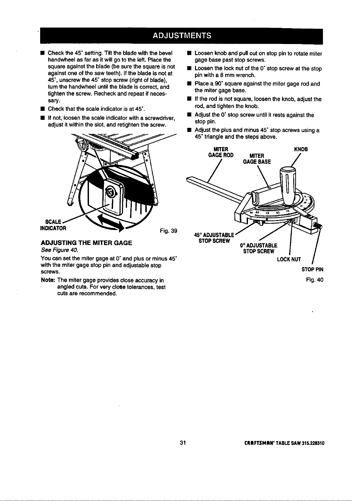
• Check the45" setting.Tiltthe bladewiththe bevel
handwheelas far as itwillgo tothe left.Place the
squareagainstthe blade (be surethe squareis not
againstone ofthe saw teeth). Ifthe bladeisnot at
45", unscrewthe 45" stop screw(rightofblade),
turnthe handwheel untilthe blade iscorrect,and
tightenthe screw. Recheck and repeat ifneces-
sary.
• Check thatthe scale indicatorisat 45°.
• If not,loosen the scale indicatorwith a screwdriver,
adjustitwithinthe slot,and retightenthe screw.
SCALE
INDICATOR
Fig. 39
ADJUSTING THE MITER GAGE
See Figure40.
You can set the mitergage at O"and plusor minus45"
withthe miter gage stop pinand adjustablestop
screws
Note: The miter gage providesclose accuracyin
angled cuts. Forvery cloSetolerances,test
cutsare recommended.
• Loosenknoband pullout on stoppinto rotatemiter
gage base paststop screws.
• Loosenthe locknutof the0"stop screwat the stop
pin with a 8 mm wrench.
• Place a 90" squareagainstthe miter gage rodand
the mitergage base.
• If the rodis notsquare, loosen theknob, adjust the
rod, and tightenthe knob.
• Adjustthe 0"stop screwuntilitrestsagainstthe
stop pin.
• Adjustthe plusand minus45" stopscrewsusinga
45"tdangle and the stepsabove.
MITER
GAGEROD MITER
GAGEBASE
KNOB
STOPSCREW
0° ADJUSTABLE
STOPSCREW
LOCKNUT
STOPPIN
Fig. 40
31 rRRFTSMRN"TABLESAW315.228310
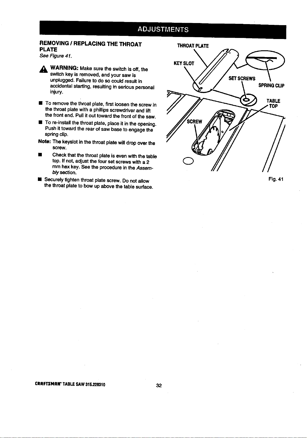
REMOVING / REPLACING THE THROAT
PLATE
See Figure41.
,_ WARNING: Make sure the switch isoff,the
switchkey is removed, and yoursaw is
unplugged.Failureto do socould resultin
accidentalstarting,resultingin sadous personal
injury.
• To remove thethroatplate,firstloosenthe screwin
the throatplatewith a phillipsscrewdriverand lift
the frontend. Pullitouttowardthe frontofthe saw.
• To re-installthethroatplate, place It inthe opening.
Push ittowardthe rear of saw base toengage the
spdngclip.
Note: The keyslotinthe throatplate willdrop over the
screw.
• Check thatthe throatplate iseven withthe table
top. Ifnot,adjustthe fourset screwswith a 2
mm hex key. See the procedureinthe Assam-
b/ysection.
• Socure_ytightenthroatplate screw. Do not allow
the throatplateto bow up above thetable surface.
THROATPLATE
KEYSLOT
SPRINGCLIP
TABLE
Fig. 41
CRIIFI3MAN" TABLESAW31tL_8310 32
BASIC OPERATION OF THE TABLE SAW
A table saw can be used for straight-linecutting
operationssuch as crosscutting,ripping,mitering,
beveling,and compoundcutting.Itcan make dado or
moldingcutswith optionalaccessories.
The three-prongplug mustbe pluggedintoa match-
ingoutletthat is propeityinstalledand grounded
accordingto all localcodes and ordinances.Improper
connectionofthe equipmentcan resultin electdc
shock.Check with an electricianor service personnel
if you are unsure about propergrounding, Do not
modifythe plug;if itwill notfit the outlet, have the
correctoutletinstalledby a qualifiedelectrician.Refer
tothe Electricalpage of this manual.
Note: Thistable sew isdesignedto cutwoodand
woodcompositionproductsonly.
CAUSES OF KICKBACK
Kickbackcan occurwhen the blade stallsor binds,
kickingthe workpieceback towardyou with great
force end speed, if yourhands are near the sewblade,
they may be jerked loose fromthe workpieceand may
contactthe blade. Obviously, kickbackcan cause
seriousinjury, and it iswell worthusing precautionsto
avoidthe risks.
Kickbackcan be caused by any actionthat pinches
the bladein the wood, such as thefollowing:
• Makinga cut with incorrectblade depth
• Sawingintoknots or nailsin the workpiece
• Twistingthe woodwhilemakinga cut
• Failingto supportwork
• Forcinga cut
• Cuttingwarpedor wet lumber
• Usingthe wrongblade for the type ofcut
• Not following correct operatingprocedures
• Misusingthe saw
• Fai{ingto usethe ant'vkickback pawls
• Cutting witha dull, gummed-up, or improperlyset
blade
AVOIDING KICKBACK
• Always use the correct blade depth setting. The
top of the blade teeth shouldclear the workpiece
by 1/8 in. to 1/4 in.
• Inspectthe work for knotsor nailsbeforebeginning
a cut. Knockout any looseknotswitha hammer.
Never saw intoa loose knot or nail.
• Always use the rip fence when ripcuttingand the
mitergage when crosscutting.This helpsprevent
twisting the wood in the cut.
• Always use clean, sharp, and properly-set blades.
Never make cutswith dull blades.
• To avoidpinchingthe blade,supped the work
properlybeforebeginning a cut.
• When making a cut, usesteady, evenpressure.
Never force cuts.
• Do notcut wet or warpedlumber.
• Always hold yourworkpiecefirmlywithbothhands
or with pushsticks.Keep yourbodyin a balanced
positionto be ready toresistkickbackshouldit
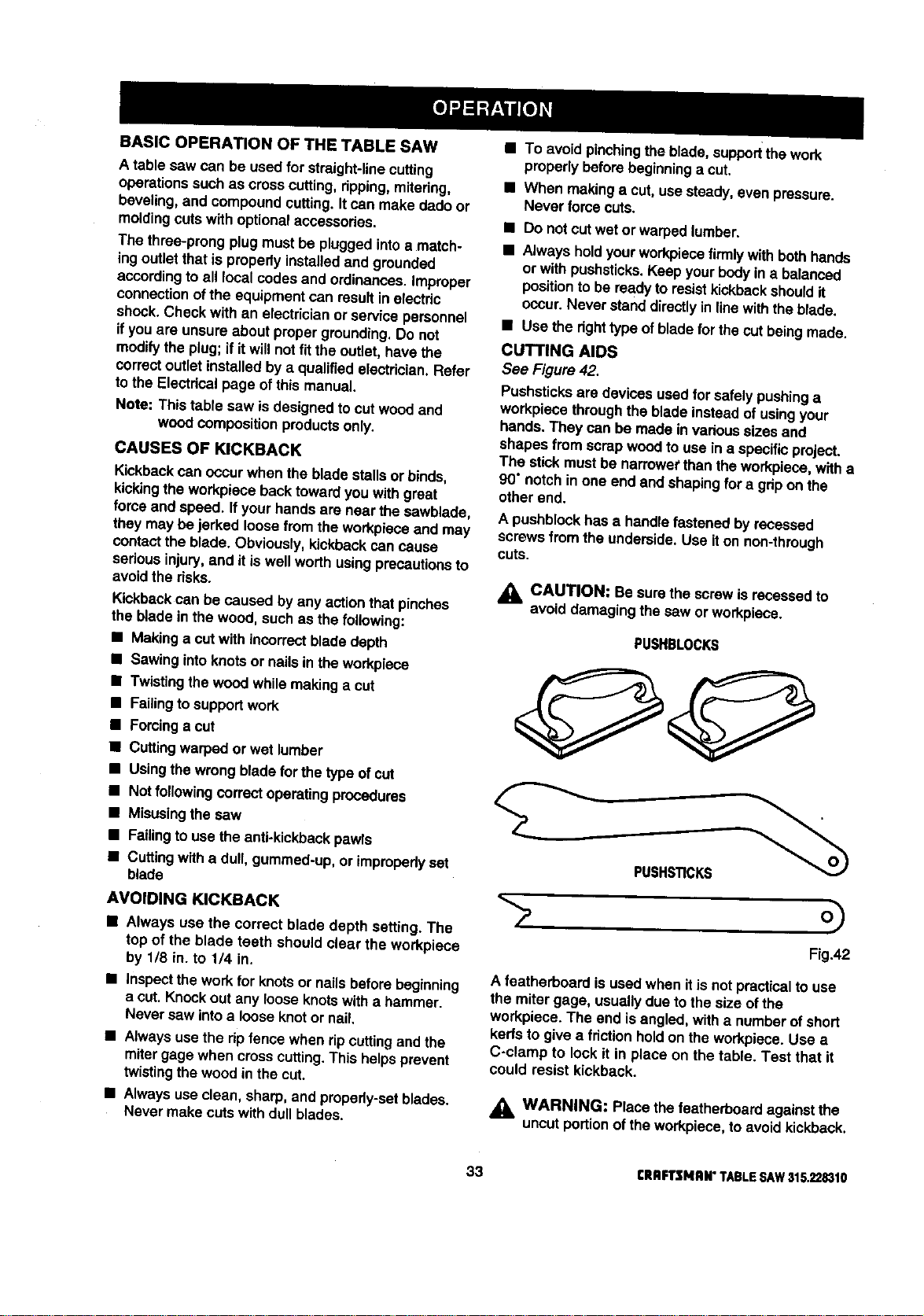
occur. Never stand directlyin line withtheblade.
• Use the dghttype ofbladefor thecut beingmade.
CUTTING AIDS
See Figure42.
Pushsticksare devices used for safelypushinga
workpiecethroughthe blade insteadof usingyour
hands. They can be made in varioussizes and
shapes from scrap woodto usein a specificproject.
The stickmustbe narrewet than the workpiece,witha
90" notchin one end and shapingfor a gripon the
other end.
A pushblockhas a handle fastened by recessed
screwsfrom the underside,Use iton non-through
cuts.
_IL CAUTION: Be sure the screwis recessedto
avoiddamagingthe saw or workpiece.
PUSHBLOCKS
PUSHSTICKS
Fig.42
A featherboard is usedwhen itis notpracticalto use
the miter gage, usuallydue to the size ofthe
workpieca.The end isangled, witha number ofshort
kerfstogive a friction hold on theworkpiece.Use a
C-clamp to lock it in place on the table. Test that it
could resist kickback.
,_ WARNING: Placethe featherboardagainstthe
uncut portionofthe workpiece,to avoid kickback.
33 CRBFTSMRN"TABLESAY/$15.22_10
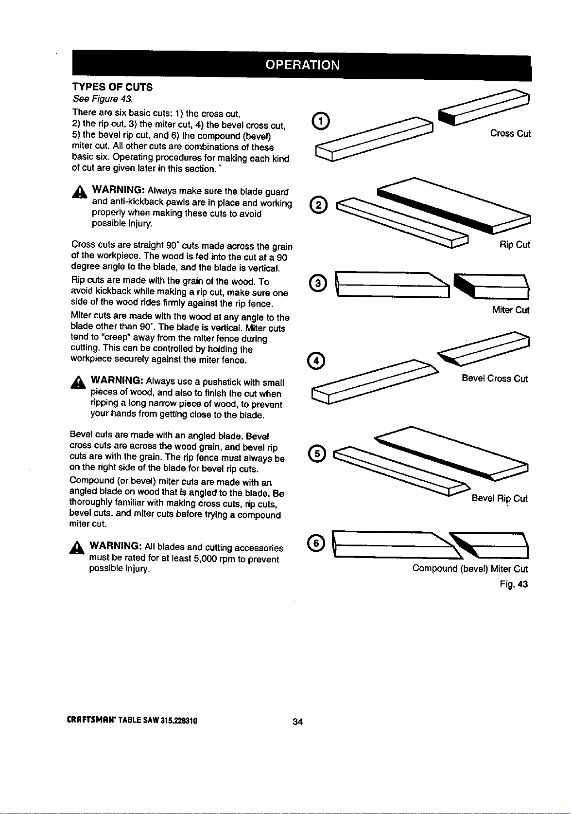
TYPES OF CUTS
See Figure 43.
There are sixbasic cuts:t ) the crosscut,
2) the ripcut, 3) the mitercut, 4) the bevel crosscut,
5) the bevel ripcut, and 6) the compound(bevel)
miter cut. Allother cuts are combinations ofthese
basicsix. Operating proceduresfor makingeach kind
of cutare given later in this sect'lon."
_. WARNING: Always make sure the blade guard
and anti-kickbackpawls are in place and working
properlywhen makingthese cutstoavoid
possibleinjury.
Cross cuts are straight90"cutsmade across the grain
ofthe workpiece.The wood isfed intothe cutat a 90
degree angle tothe blade, and the blade isvertical,
Ripcutsare made withthe grain ofthe wood. To
avoid kickbackwhilemakinga ripcut, make sure one
side of the woodridesfirmly againstthe ripfence.
Mitercutsare made withthe wood at any angle tothe
bladeotherthan 90". The blade is vertical.Mitercuts
tend to "creep" away from the miter fence during
cutting.This can be controlledbyholdingthe
workpiece securelyagainst the miterfence.
_, WARNING: Always usea pushstickwith small
pieces of wood, and also tofinish thecut when
rippinga longnarrowpiece ofwood, to prevent
your handsfrom gettingcloseto the blade.
Bevel cuts are made with an angled blade. Bevel
crosscuts are across the wood grain,and bevel rip
cuts are with the grain.The ripfence mustalways be
on the rightside ofthe blade for bevel ripcuts.
Compound (or bevel) miter cutsare made with an
angled blade on woodthat isangled tothe blade. Be
thoroughlyfamiliar with making cross cuts, dp cuts,
bevel cuts, and miter cutsbefore tryinga compound
mitercut.
_, WARNING: All blades and cuttingaccessodes
mustbe rated for at least 5,000 rpm to prevent
possibleinjury.
CrossCut
®
MiterCut
o
Bevel Cross Cut
Bevel Rip Cut
Compound (bevel) Miter Cut
Fig. 43
tRRFTSNRN"TABLESAW315.228310 34
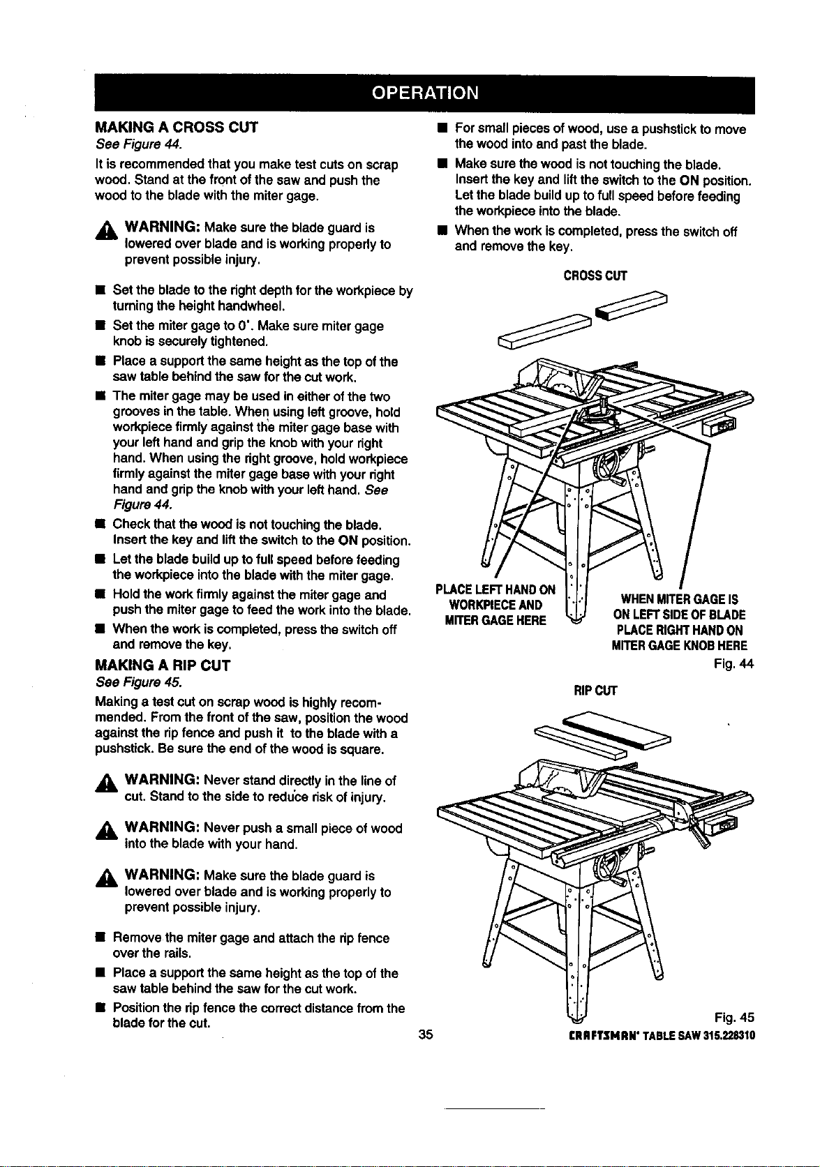
MAKING A CROSS CUT
See Figure 44.
It isrecommendedthat you make test cutson scrap
wood. Stand at the frontof the saw and pushthe
wood tothe bladewith the miter gage.
_1= WARNING: Make sure the blade guard is
lowered over bladeand isworkingproperlyto
preventpossibleinjury.
• Set the bladeto the fightdepthforthe workpieceby
tumingthe height handwheel.
• Set the mitergage to0". Make sure mitergage
knobissecurelytightened.
• Place a supportthe same heightas the top ofthe
saw table behindthe saw for thecutwork.
• The mitergage may be usedin either ofthe two
g_:_ovesin thetable. When usingleftgroove,hold
workpiecefirmlyagainsttheemitergage basewith
yourleft handand gripthe knobwithyour right
hand.When usingthe rightgroove, holdworkpiece
firmlyagainstthe mitergage basewithyour right
handand gripthe knobwith yourlefthand. See
Figure44.
• Check thatthe woodis nottouchingthe blade.
Insertthe key and liftthe switchto the ON position.
• Letthe blade buildup to fullspeed beforefeeding
the workpieceintothe bladewiththe mitergage.
• Hold the workfirmlyagainstthe mitergage and
pushthe miter gage tofeed the workintothe blade.
• When the work iscompleted,pressthe switchoff
and removethe key.
MAKING A RIP CUT
See Figure 45.
Making a test cut on scrap woodis highlyrecom-
mended. Fromthe frontof the saw, posltioothe wood
against the ripfence and pushit to the blade witha
pushstick.Be sure the end of the woodissquare.
• Forsmall piecesofwood, use a pushstickto move
the woodintoand pastthe blade.
• Make sure thewoodis nottouchingthe blade.
Insertthe key and lifttheswitchto the ON position.
Letthe bladebuildupto fullspeed beforefeeding
theworkpieceintotheblade.
• When theworkiscompleted,presstheswitchoff
and removethekey,
CROSSct,rr
PLACELEFT HANDON
WORKPIECEAND
Mn'ERGAGEHERE
WHENMITERGAGEIS
ONLEFTSIDEOFBLADE
PLACERIGHTHANDON
MITERGAGEKNOBHERE
Fig. 44
RIPCUT
WARNING: Never stand directlyInthe lineof
cut. Stand to the side to reduce riskofinjury.
WARNING: Never push a smallpiece of wood
into the bladewith your hand.
_1= WARNING: Make surethe blade guard is
lowered over blade and is workingproperlyto
preventpossibleinjury.
• Remove the mitergage and attachthe ripfence
over the rails.
• Place a supportthe same heightas thetop ofthe
saw table behindthe saw for the cutwork.
• Positionthe ripfence thecorrectdistancefromthe
blade forthe cut.
35
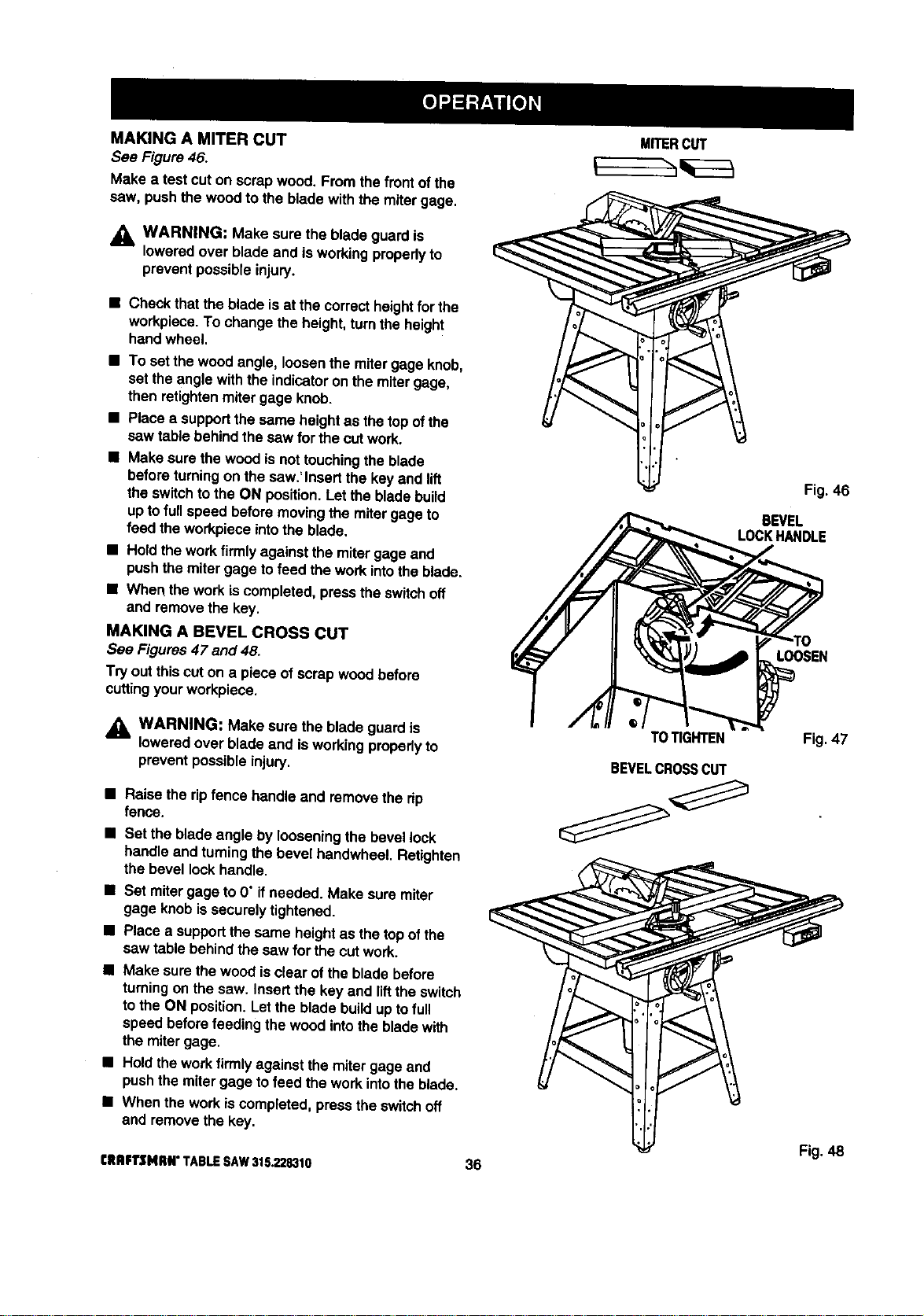
MAKINGAMITERCUT
See Figure 46.
Make a test cut on scrap wood. From thefrontofthe
caw. pushthe woodto the blade with the miter gage.
_1, WARNING: Make sure the blade guardis
loweredover blade and isworkingpropedyto
preventpossibleinjury.
• Check thatthe blade is at thecorrectheightfor the
workpiece.To change theheighLturnthe height
handwheel.
• To set the woodangle, loosenthe mitergage knob,
set theangle withthe indicatoron the mitergage,
then retightenmitergage knob.
• Place asupportthe same heightas the top ofthe
saw table behindthe saw for the cutwork.
• Make surethe woodis nottouchingthe blade
beforeturningon the saw.'Insertthe key and lift
the switchtothe ON position.Letthe bladebuild
uptofullspeed beforemovingthe mitergage to
feed the workpieceintothe blade.
• Ho_dthework firmlyagainst the miter gage aod
pushthe miter gage tofeed the work intothe blade.
• When the workiscompleted,pressthe switchoff
and remove the key,
MAKING A BEVEL CROSS CUT
See Figures47 and 48.
Try outthis cuton a piece ofscrap wood before
cuttingyourworkpiece.
_k WARNING: Make sure the blade guardis
loweredover blade and is workingpropedyto
prevent possibleinjury.
• Raise the ripfence handleand remove the rip
fence.
• Set the bladeangle by looseningthe bevel lock
handle and turningthe bevel handwheel. Retighten
the bevel lockhandle.
• Set mitergage to 0" ifneeded. Make sure miter
gage knobissecurelytightened.
• Place a supportthe same heightas thetop ofthe
saw table behindthesaw for the cutwork.
• Make sure thewood isclear ofthe blade before
turningonthe saw. Insertthe key and liftthe switch
to the ON position.Letthe bladebuildup tofull
speed beforefeeding thewood intotheblade with
the mitergage.
• Holdthe workfirmlyagainst the miter gage and
pushthe mitergage tofeed the work intothe blade.
• When thework is completed,press theswitchoff
and removethe key.
CRBFT$141_#° TABLESAW315.228310
36
MITERCUT
TOTIGHTEN
BEVELCROSSCUT
Fig. 46
BEVEL
LOCKHANDLE
LOOSEN
Fig. 47
Fig. 48
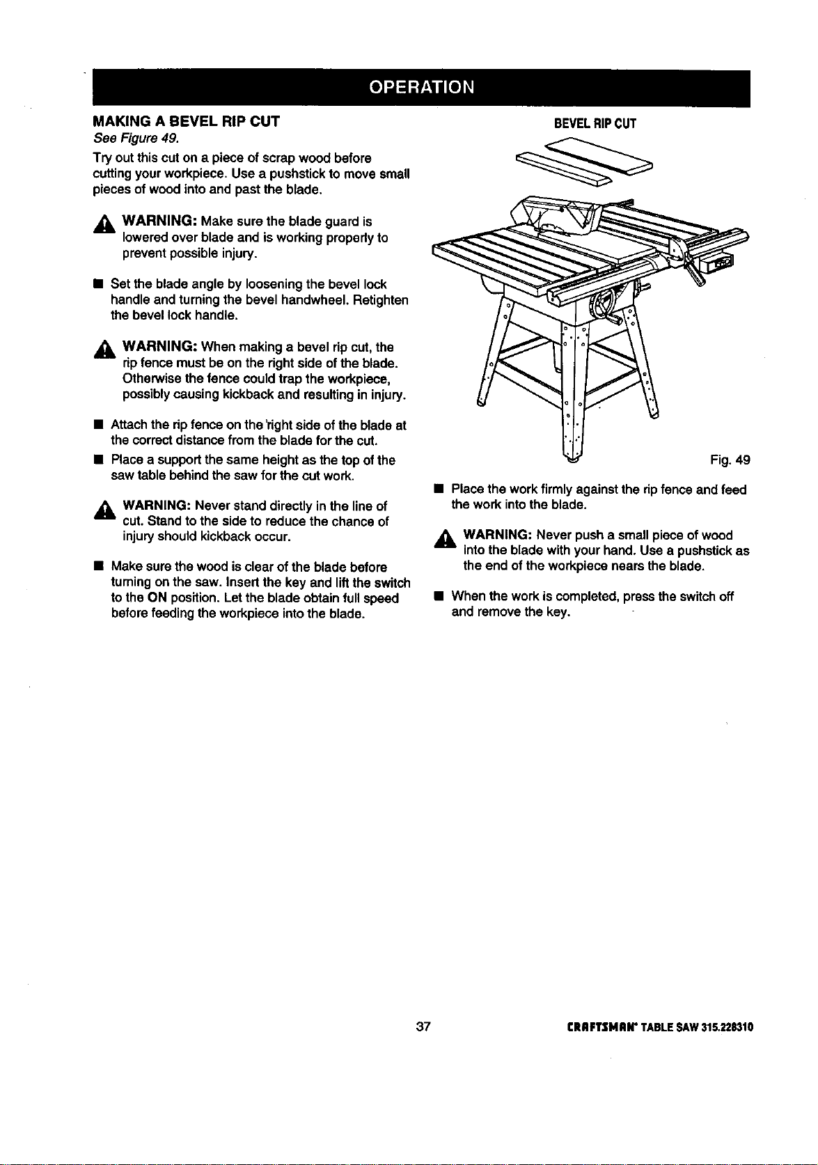
MAKINGA BEVELRIPCUT
See Figure49.
Try out thiscut on a piece of scrap wood before
cuttingyourworkpiece.Use a pushstickto movesmall
pieces of woodintoand pastthe blade.
_, WARNING: Make sure the blade guard is
loweredover blade and isworkingpropedyto
preventpossibleinjury.
• Set the bladeangle by loosening the bevel lock
handle and turningthe bevel handwheel. Retighten
the bevel lock handle.
,_k WARNING: When makinga bevel ripcut, the
dp fence mustbe on the rightside ofthe blade.
Otherwisethe fence could trap the workpiece,
possiblycausing kickbackand resultingin injury.
• Attachthe dp fenceon the'dghtside of the bladeat
the correctdistancefrom the blade forthe cut.
• Placea supportthe same heightas the top ofthe
saw table behindthe saw for the cutwork.
_1= WARNING: Never stand directly in the line of
cut. Stand to the side to reduce the chance of
injury should kickback occur.
• Make surethe woodis clear ofthe blade before
turningon the saw. Insertthe key and liftthe switch
to the ON position.Letthe blade obtainfull speed
beforefeeding theworkpiece intothe blade.
BEVELRIPCUT
Fig. 49
• Place the workfirmlyagainstthe ripfence and feed
the work intothe blade.
,_ WARNING: Never pusha small pieceof wood
intothe blade withyourhand. Use a pushstickas
theend of theworkpiece nears the blade.
• When the work iscompleted,presstheswitchoff
and removethe key.
37 CRAFTSMAN"TABLESAW315.228310
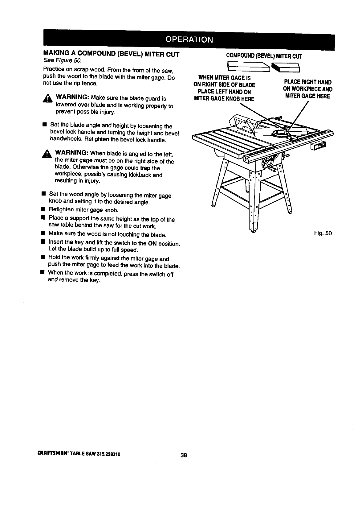
MAKING A COMPOUND (BEVEL) MITER CUT
Sea Figure50.
Practice on scrap wood. Fromthe frontofthe sew,
pushthe woodto the bladewith the mitergage. Do
not use the ripfence.
WARNING: Make sure the blade guard is
lowered overblade and isworkingproperlyto
prevent possibleinjury.
• Set the bladeangle and heightbylooseningthe
bevel lock handleand turningthe heightand bevel
handwheeis. Retightenthe bevel lockhandle.
,_ WARNING: When blade isangled tothe left,
the miter gage must be onthe dghtside of the
blade. Otherwise the gage couldtrap the
workpiece,possiblycausingkickbackand
resultingin injury.
• Set the woodangle byloosening the miter gage
knoband settingitto the desiredangle.
• Retightenmitergage knob.
• Place a supportthe same heightas thetop ofthe
saw table behindthe saw for the cutwork.
II Make surethe woodis nottouchingthe blade.
• Insertthe kay and liftthe switchtothe ON position.
Letthe blade buildupto full speed.
• Hold thework firmly againstthe mitergage and
pushthe miter gage tofeed the workintothe blade.
• When the workis completed,press the switchoff
and removethe key.
COMPOUND(BEVEL)MITERCUT
WHENMITERGAGEIS
ONRIGHTSIDEOFBLADE
PLACELEFTHANDON
MITERGAGEKNOBHERE
PLACERIGHTHAND
ONWORK,PIECEAND
MITERGAGEHERE
Fig. 50
CRRFTSI4RN"TABLESAW315.228310 38
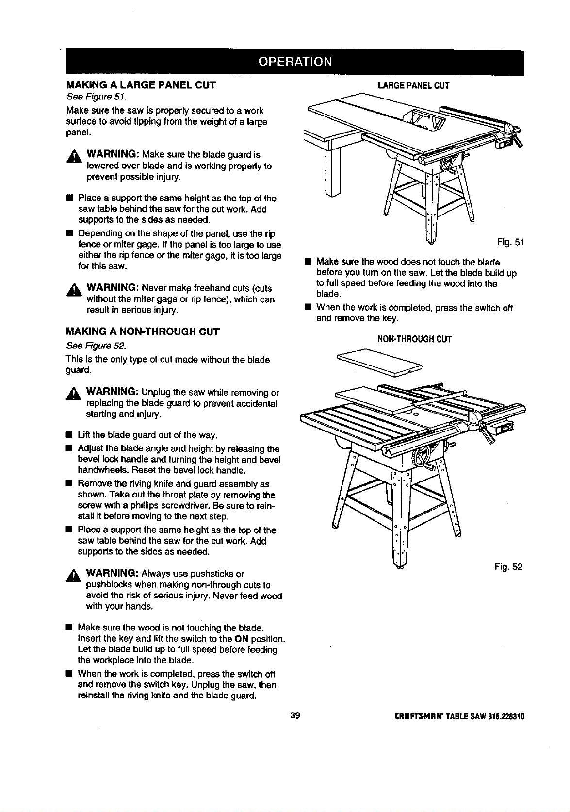
MAKING A LARGE PANEL CUT
See Figure51.
Make sure the saw isproperlysecuredto a work
surfaceto avoidtippingfrom the weightofa large
panel.
_k WARNING: Make sure the blade guard is
lowered over blade and is working properly to
prevent possibleinjury.
• Placea supportthe same heightas the top ofthe
saw table behindthesaw for the cutwork.Add
supportstothe sides as needed.
• Dependingon the shape ofthe panel, usethe rip
fence or miter gage. Ifthe panel istoo largeto use
eitherthe ripfence or the mitergage, it istoo large
for thissaw.
_l, WARNING: Never makpfreehand cuts(cuts
withoutthe miter gage or ripfence), whichcan
resultin seriousinjury.
MAKING A NON-THROUGH CUT
See Figure 52.
This isthe onlytype ofcut made withoutthe blade
guard.
,_, WARNING: Unplugthe saw while removingor
replacingthe blade guardto preventaccidental
startingand injury.
• Liftthe bladeguard out ofthe way.
• Adjustthe blade angle and heightby releasingthe
bevel lockhandle and turningthe heightand bevel
handwheels. Resetthe bevel lockhandle.
• Remove the rivingknife and guard assemblyas
shown.Take outthe throatplate by removingthe
screwwitha phillipsscrewdriver.Be sure torein-
stall itbeforemovingtothe next step.
• Place a supportthe same heightas thetop ofthe
saw table behindthe saw for the cutwork. Add
supportsto the sidesas needed.
,_ WARNING: Always use pushsticksor
pushblockswhen making non-throughcutsto
avoid the riskof seriousinjury.Never feed wood
with yourhands.
LARGEPANELCUT
Fig. 51
• Make surethe wooddoes nottouchtheblade
before you turnon thesaw. Lettheblade buildup
tofull speed beforefeeding the woodintothe
blade.
• When the work iscompleted,presstheswitchoff
and remove the key.
NON_HROUGHCUT
Fig. 52
• Make sure the woodis nottouchingthe blade.
Insertthe key and liftthe switchto the ON position.
Letthe blade buildupto full speed beforefeeding
the workpiece intothe blade.
• When the workis completed,pressthe switchoff
and removethe switchkey. Unplugthe saw, then
reinstallthe rivingknifeand the blade guard.
39 CRIIFTSMRN" TABLE SAW 315,228310
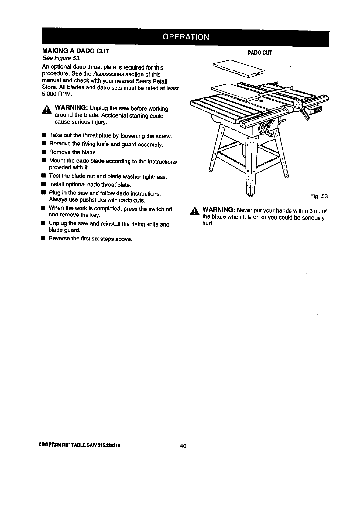
MAKING A DADO CUT
See Figure 53.
An optionaldado throatplate is requiredfor this
procedure.See the Accessoriessectionof this
manual and check withyournearest Sears Retail
Store. Allblades and dado sets mustbe ratedat least
5,000 RPM,
_L WARNING: Unplugthe saw beforeworking
around the blade. Accidentalstartingcould
cause serious injury.
• Take outthe throatplate bylooseningthe screw.
• Remove the rivingknife and guardassembly,
• Remove the blade.
• Mount the dadoblade accordingto the instructions
providedwith it.
• Test the blade nutand blade washertightness.
• Installoptionaldadothmat'plate.
• Plugin thesaw and follow dado instructions.
Always use pushstickswith dadocuts.
• When the workiscompleted,presstheswitchoff
and remove the key.
• Unplugthe saw and reinstallthe dvingknifeand
bladeguard.
• Reverse the firstsixstepsabove.
DADOCUT
Fig, 53
WARNING: Never putyour handswithin3 in.of
the bladewhen it ison or you could be seriously
hurt.
CRIIFTSMAN" TABLE SAW 315.228310 40
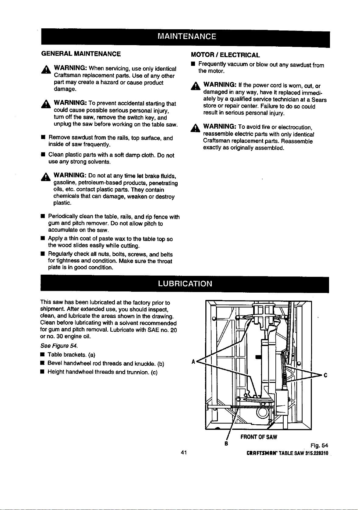
GENERAL MAINTENANCE
_k WARNING: When servicing,use onlyidentical
Craftsman replacement pads. Use ofany other
part may create a h_o.ardor cause product
damage.
WARNING: To preventaccidental startingthat
couldcause possibleserious personalinjury,
turn offthesaw, remove the switch key, and
unplugthe saw beforeworkingon the table saw.
• Remove sawdustfrom the rails, top surface, and
inside ofsaw frequently.
• Clean plasticpartswith a softdamp cloth. Do not
useany strongsolvents.
_, WARNING: Do not at any time let brake fluids,
gasoline, petroleum-basedproducts,penetrating
oils, etc. contactplasticpads. They contain
chemicalsthatcan damage, weaken or destroy
plastic.
• Pedodicallyclean the table, rails, and dp fence with
gum and pitchremover. Do not allow pitchto
accumulate onthe saw.
• Apply a thincoat of pastewax to the table top so
the woodslideseasily while cutting.
• Regularlycheck all nuts,bolts, screws, and belts
for tightnessand condition.Make sure the throat
plate is in goodcondition.
MOTOR / ELECTRICAL
• Frequently vacuum or blowout any sawdustfrom
the motor.
_l, WARNING: If the power cordis worn, cut, or
damaged in any way, have itreplaced immedi-
ately bya qualifiedservice technicianat a Sears
store or repair center. Failureto do socould
resultin serious personalinjury.
WARNING: To avoid fireor electrocution,
reassemble electricpartswith onlyidentical
Craftsman replacement pads. Reassemble
exactly as originallyassembled.
This saw has been lubricatedat thefactory priorto
shipment.After extended use, you shouldinspect,
clean, and lubricatethe areas shown inthe drawing.
Clean before lubricatingwith a solventrecommended
for gumand pitchremoval. Lubricatewith SAE no. 20
or no. 30 engine oil.
See Figure54.
• Table brackets.(a)
• Bevel handwheelrodthreadsand knuckle.(b)
• Height handwheelthreadsand trunnion.(c)
41
B
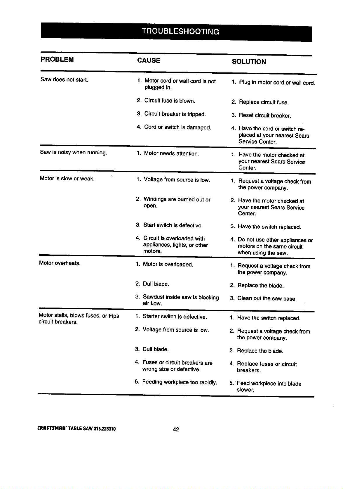
PROBLEM CAUSE SOLUTION
Sawdoesnotstart. 1. Motorcordorwallcordisnot 1. Pluginmotorcordorwallcord.
pluggedin.
2. Circuitfuseisblown.
3. Cimuitbreakeristripped.
4. Cordorswitchisdamaged.
Sawisnoisywhenrunning.
Motorissloworweak.
Motoroverheats.
Motorstalls,blowsfuses,ortrips
circuitbreakers.
1. Motor needs attention.
1. Voltage from sourceislow.
2. Windingsare burnedout or
open.
3. Start switchis defective.
4. Circuit is overloaded with
appliances, lights, or other
motorS.
1. Motor isoverloaded.
2. Du$$blade.
3. Sawdust insidesaw is blocking
air flow.
1. Starter switchisdefective.
2. Voltage from sourceis low.
3. Dull blade.
4. Fuses or circuitbreakersare
wrong size or defective.
5, Feeding workplacetoo rapidly,
2. Replace circuitfuse.
3. Reset circuitbreaker.
4. Have the cordor switchre-
placed at your nearest Sears
Service Center.
1. Have the motorcheckedat
your nearest Sears Service
Center.
1. Requesta voltagecheckfrom
the powercompany.
2, Have the motorcheckedat
yournearest Sears Service
Center.
3, Have the switch replaced.
4. Do not use otherappliances or
motorson thesame circuit
when usingthe saw.
1. Request a voltagecheckfrom
the power company.
2. Replace the blade.
3. Clean out thesaw base.
1. Have the switch replaced.
2. Request a voltage checkfrom
the powercompany.
3. Replace the blade.
4. Replace fuses or circuit
breakers.
5. Feed work,piece intoblade
slower.
CRIIFTSNRN"TABLESAW315.228310 42
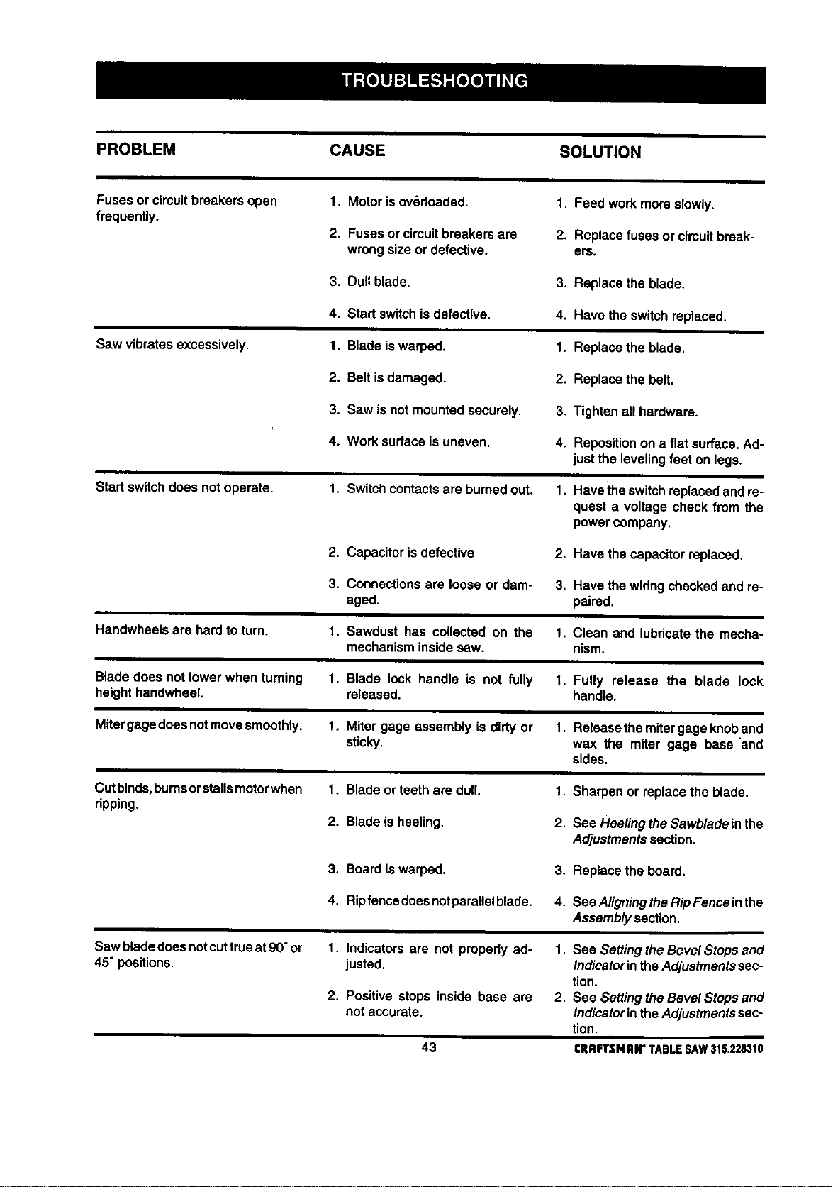
PROBLEM CAUSE SOLUTION
Fuses or circuitbreakersopen
frequently.
1. Motor isoverloaded.
2. Fuses or circuitbreakersare
wrongsize or defective.
1. Feed work more slowly.
2. Replace fuses or circuit break-
ers,
3. Dull blade. 3. Replace theblade.
Saw vibratesexcessively.
4. Startswitchis defective.
1. Blade iswarped.
4. Have the switchreplaced.
1. Replacethe blade.
2. Belt isdamaged,
2. Replacethe belt.
3. Saw isnot mountedsecurely. 3, Tightenall hardware.
4. Work surface isuneven.
4. Repositionon a flat surface.Ad-
justthe leveling feet on legs.
Start switchdoes not operate.
1. Switch contactsare burned out. 1. Havetheswitchreplaced andre-
quest a voltage check from the
powercompany.
2. Capacitoris defective
2. Havethe capacitor replaced.
3. Connectionsare looseor dam- 3. Havethe widngchecked and re-
aged. paired.
Handwheelsare hardto turn.
1. Sawdust has collected on the 1. Clean and lubricatethe mecha-
mechanisminsidesaw. nism.
Bladedoes not lowerwhen turning
heighthandwheel.
1. Blade lock handle is not fully 1. Fully release the blade lock
released, handle.
Mitergagedoesnotmovesmoothly.
1. Miter gage assembly is dirtyor 1. Release themitergage knoband
sticky, wax the miter gage base _and
sides.
Cutbinds,bumsorstallsmotorwhen
ripping.
1. Blade orteeth are dull,
2. Blade isheeling.
1. Sharpen or replacethe blade.
2. See Hee/ingtheSawbladeinthe
Adjustmentssection.
3. Board iswarped. 3. Replace the board.
4. Ripfencedoesnotparallelblade. 4. SeeAligningtheRipFenceinthe
Assemblysection.
Saw bladedoes notcuttrueat90"or 1.
45" positions.
2.
Indicators are not properly ad-
justed.
Positive stops inside base are
notaccurate.
1. See SettingtheBevel Stops and
IndicatorintheAdjustmentssec-
tion.
2. See SettingtheBevel Stops and
IndicatorintheAdjustmentssec-
tion.
43 CRAFTSMRN"TABLESAW315.228310
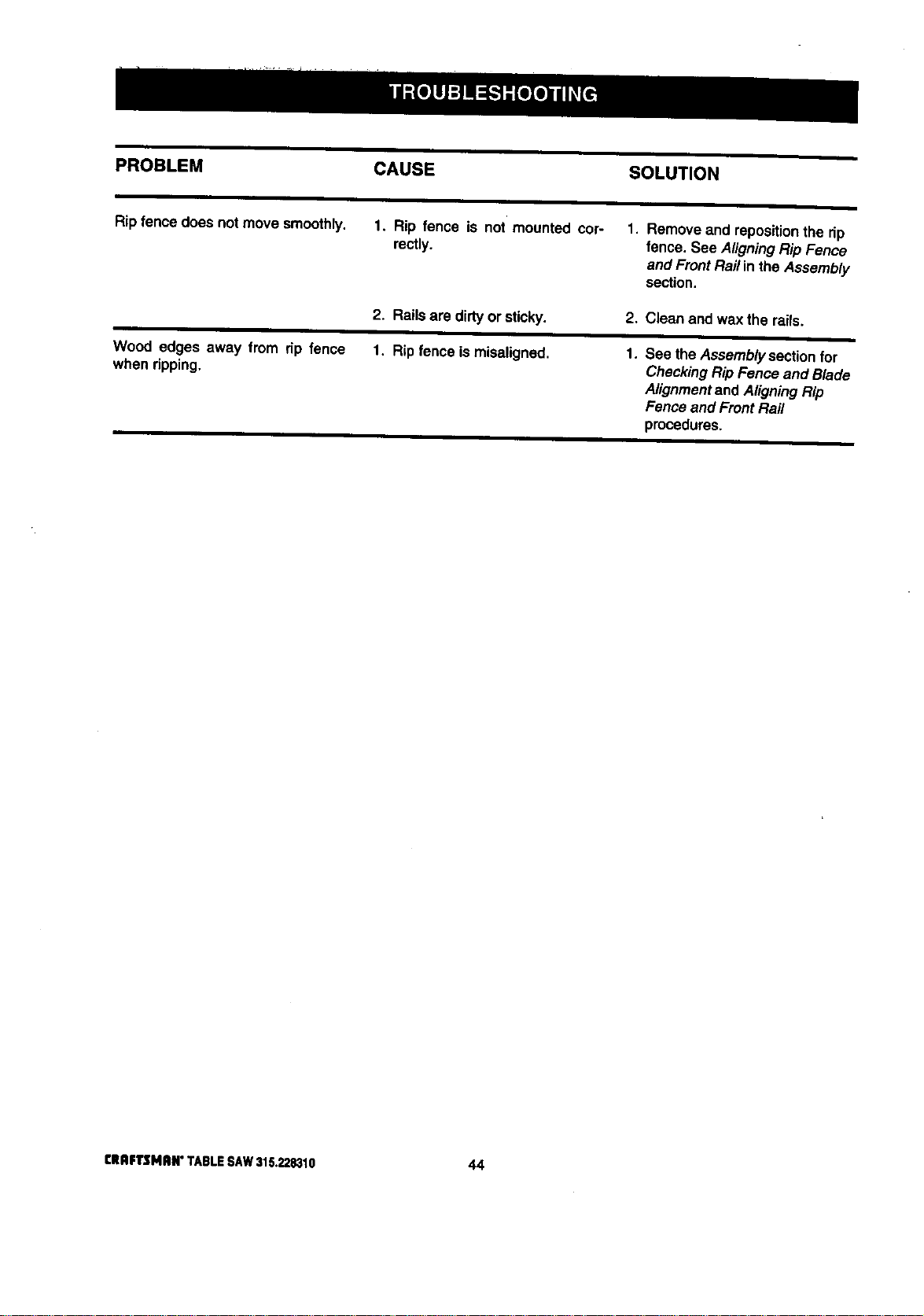
PROBLEM CAUSE SOLUTION
Ripfence does not move smoothly. 1. Rip fence is not mounted cor-
rectly.
1. Remove and repositionthe rip
fence. See AligningRip Fence
and Front Railin the Assembly
section.
2. Railsare dirtyor sticky.
2. Clean and wax the mils.
Wood edges away from rip fence
when ripping.
1. Ripfence is misaligned.
1. See the Assemblysectionfor
CheckingRip Fence and Blade
Alignmentand AligningRip
Fence and Front Rail
procedures.
CRIIFTSMlU4"TABLESAW3_G.22834,0 44

45 CRRFTSMAN" TABLE SAW 315.228310
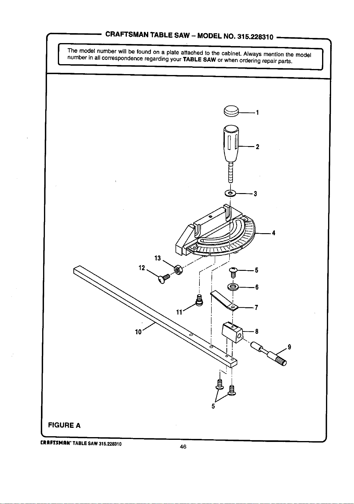
CRAFTSMAN TABLE SAW - MODEL NO. 315.228310
I The model number will be found on a plate attached to the cabinet. Always mention the model !
numberin all correspondenceregardingyourTABLE SAW or when orderingrepairpads.
I
12
FIGURE A
CRIIFTSMRN" TABLE SAW 315.228310
46
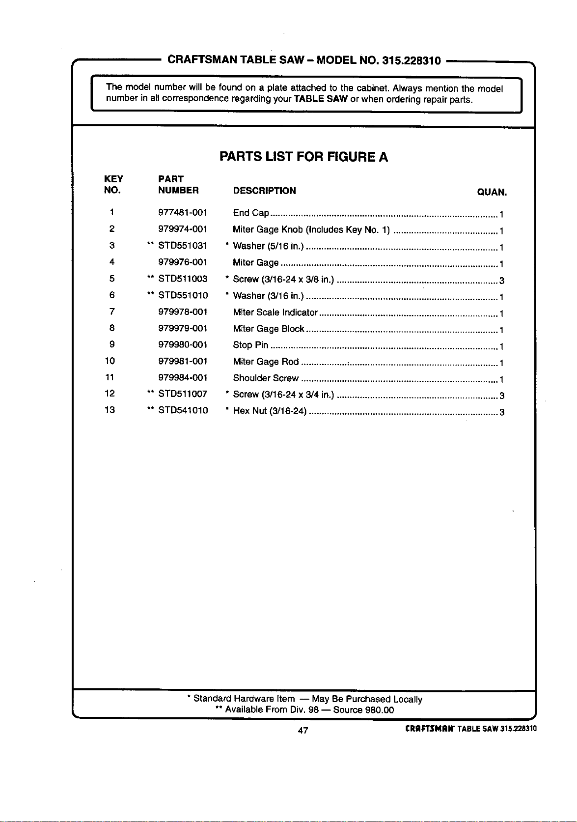
CRAFTSMAN TABLE SAW - MODEL NO. 315.228310
I The model number will be found on a plate attached to the cabinet. Always mention the model I
number in all correspondenceregardingyourTABLE SAW or when orderingrepair parts.
I
PARTS LIST FOR FIGURE A
KEY PART
NO. NUMBER DESCRIPTION QUAN.
1 977481-001
2 979974-001
3 ** STD551031
4 979976-001
5 ** STD511O03
6 ** STD55t010
7 979978-001
8 979979-001
9 979980-001
10 979981-001
11 979984-001
12 ** STD511007
13 ** STD541010
End Cap......................................................................................... 1
Miter Gage Knob (Includes Key No. 1) ......................................... 1
* Washer (5/16 in.) ........................................................................... 1
Miter Gage ..................................................................................... 1
* Screw (3/16-24 x 3/8 in.) ............................................................... 3
* Washer (3/16 in.) ........................................................................... 1
Miter Scale Indicator...................................................................... 1
Miter Gage Block........................................................................... 1
Stop Pin ......................................................................................... 1
Miter Gage Rod ...................,.......................................................... 1
Shoulder Screw ............................................................................. 1
* Screw (3/16-24 x 3/4 in.) ............................................................... 3
* Hex Nut (3/16-24) .......................................................................... 3
• Standard Hardware Item -- May Be Purchased Locally
** Available From Div. 98 -- Source 980.00
47 CRAFTSMAN"TABLESAW315.228310
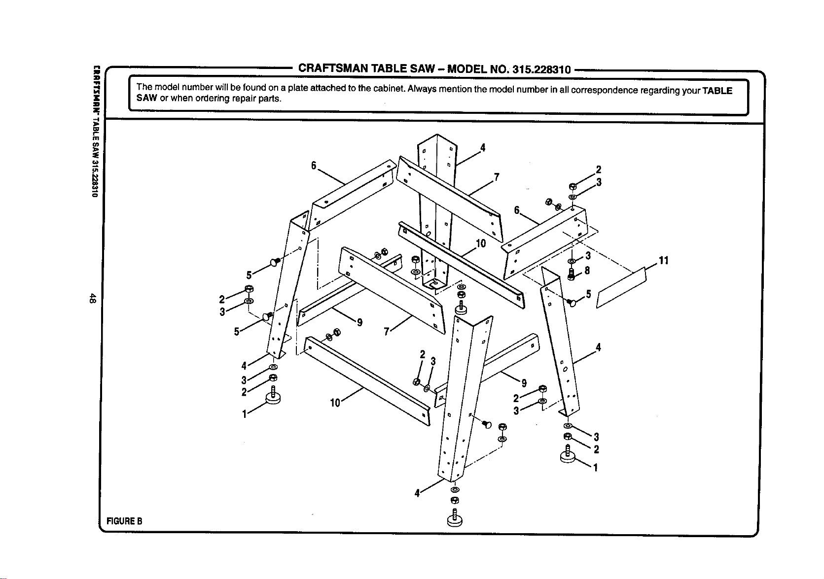
i
.-I
:D.
l:U
m
(n
o
FIGUREB
k
CRAFTSMAN TABLE SAW - MODEL NO. 315.228310
The modelnumberwillbefoundona plate attachedtothe cabinet.Alwaysmentionthe modelnumberinall correspondenceregardingyourTABLE i
SAW orwhen orderingrepair parts.
J
3
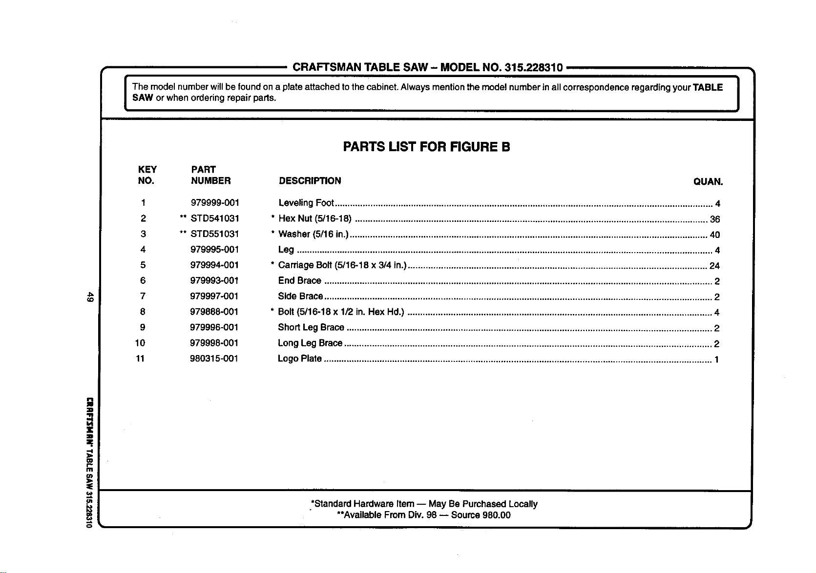
CRAFTSMANTABLESAW- MODELNO.315.228310
I he modelnumberwillbefoundona plate attached to thecabinet.Alwaysmentionthemodelnumberinall correspondenceregardingyourTABLE J
SAW or when orderingrepair parts.
I
(o
m
r
f11
=E
,e.
PARTS LIST FOR FIGURE B
KEY PART
NO. NUMBER DESCRIPTION QUAN.
1 979999-001
2 ** STD541031
3 ** STD551031
4 979995-001
5 979994-001
6 979993-001
7 979997-001
8 979888-001
9 979996-001
10 979998-001
11 980315-001
LevelingFoot..................................................................................................................................................... 4
* Hex Nut (5/16-18) ........................................................................................................................................... 36
* Washer (5/16 in.)............................................................................................................................................. 40
Leg .................................................................................................................................................................... 4
* Carriage Bolt(5/16-18 x 3/4 in.)...................................................................................................................... 24
End Brace ......................................................................................................................................................... 2
Side Brace......................................................................................................................................................... 2
* Bolt(5/16-18 x 1/2 in. Hex Hd.) ........................................................................................................................ 4
Short Leg Brace ................................................................................................................................................ 2
Long Leg Brace................................................................................................................................................. 2
Logo Plate......................................................................................................................................................... 1
*StandardHardware Item-- May Be Purchased Locally
**AvailableFromDiv. 98 -- Source 980.00
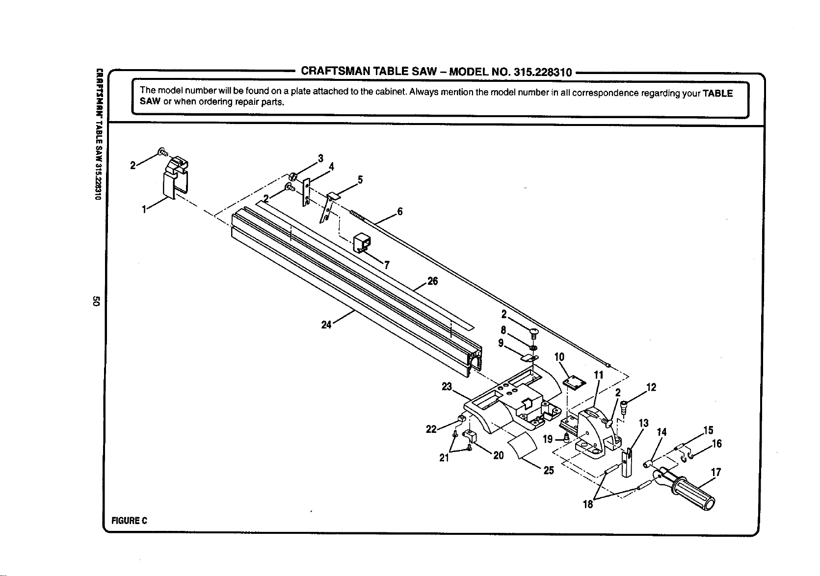
i
¢,m
o
O1
O
CRAFTSMAN TABLE SAW - MODEL NO. 315.228310
I he modelnumberwillbe foundon a plateattached tothecabinet.Always mentionthe modelnumberin all correspondenceregardingyourTABLE !
SAW or when orderingrepair parts.
I
24'
21
10
11
25
13
14
17
FIGUREC
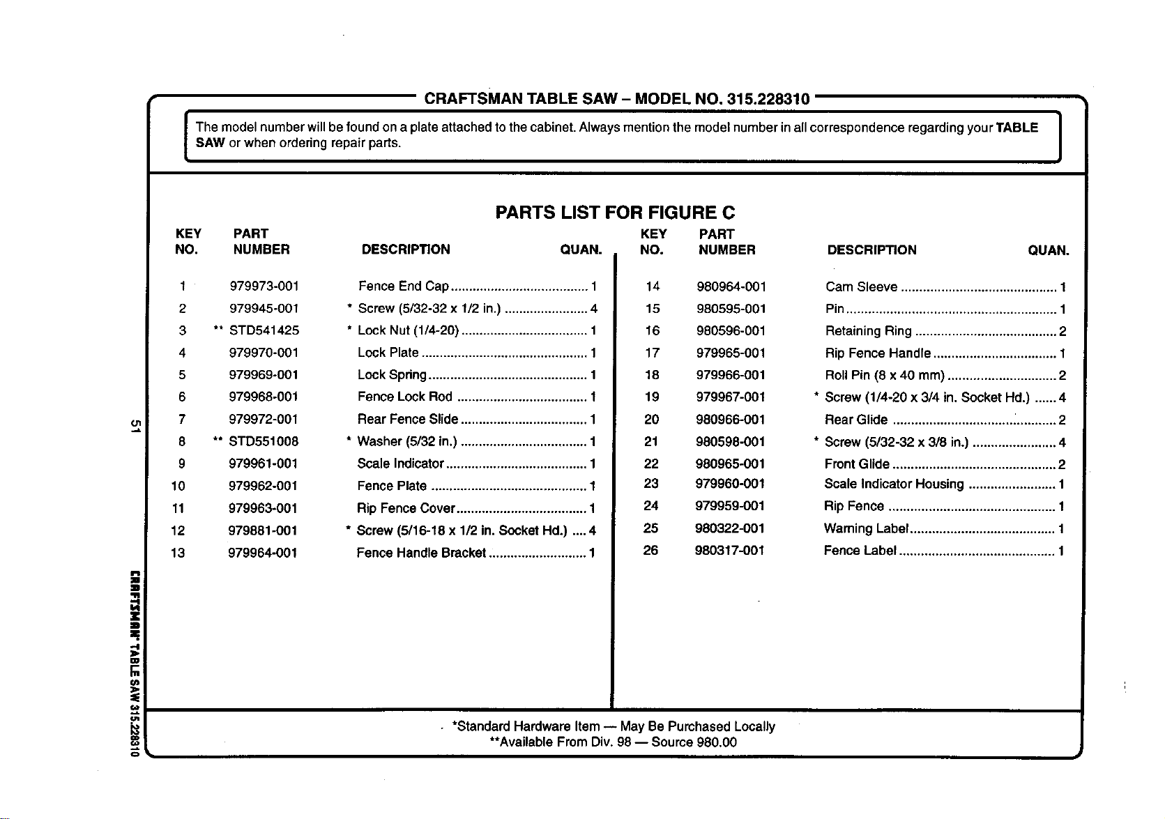
i
al
CRAFTSMAN TABLE SAW- MODEL NO, 315.228310
I The model numberwillbe foundon a plate attached to the cabinet. Always mention the model number in all correspondence regarding yourTABLE |
I
SAW or when ordering repair parts.
I
PARTS LIST FOR FIGURE C
KEY PART KEY PART
NO. NUMBER DESCRIPTION QUAN. NO. NUMBER DESCRIPTION QUAN.
1 979973-001
2 979945-001
3 ** STD541425
4 979970-001
5 979969-001
6 979968-001
7 979972-001
8 ** STD551008
9 979961-001
10 979962-001
11 979963-001
12 979881-001
13 979964-001
Fence End Cap...................................... 1
* Screw (5/32-32 x 1/2 in.) ....................... 4
* Lock Nut (1/4-20) ................................... 1
Lock Plate .............................................. 1
Lock Spdng ............................................ 1
Fence Lock Rod .................................... 1
Rear Fence Slide................................... 1
* Washer (5/32 in.) ................................... 1
Scale Indicator ....................................... 1
Fence Plate ........................................... 1
Rip Fence Cover .................................... 1
* Screw (5/16-18 x 1/2 in.Socket Hd.) .... 4
Fence Handle Bracket ........................... 1
14 980964-001
15 980596-001
16 980596-001
17 979965-001
18 979966-001
19 979967-001
20 980966-001
21 980598-001
22 980965-001
23 979960-001
24 979959-001
25 980322-001
26 980317-001
Cam Sleeve ........................................... 1
Pin .......................................................... 1
Retaining Ring ....................................... 2
Rip Fence Handle .................................. 1
Roll Pin (8 x 40 mm) .............................. 2
Screw (1/4-20 x 3/4 in. Socket Hal.) ...... 4
Rear Glide ............................................. 2
Screw (5/32-32 x 3/8 in.) ....................... 4
Front Glide ............................................. 2
Scale Indicator Housing ........................ 1
Rip Fence .............................................. 1
Waming Label ........................................ 1
Fence Label ........................................... 1
• *Standard Hardware Item-- May Be Purchased Locally
**AvailableFrom Div.98 -- Source 980.00
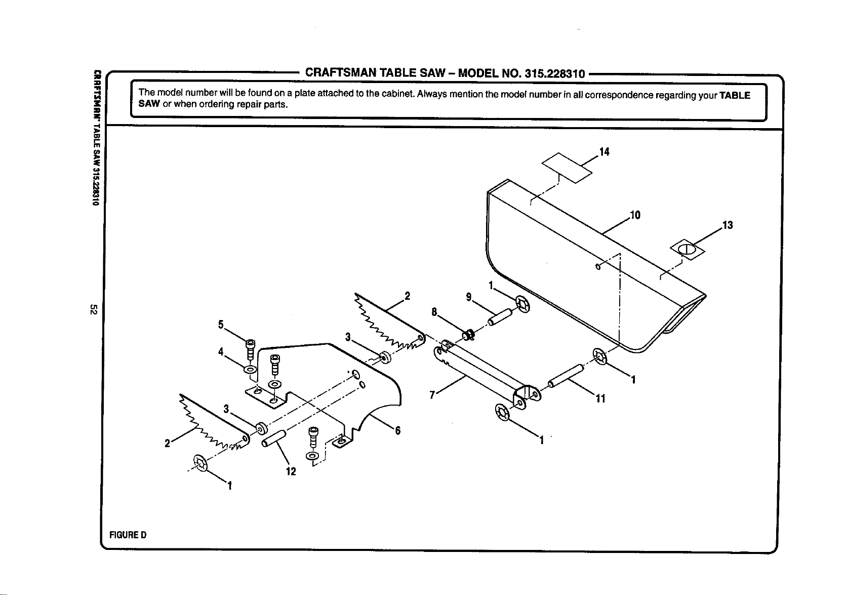
i
O1
I%1
CRAFTSMAN TABLE SAW - MODEL NO. 315.228310
I The modelnumberwillbefound ona plateattachedtothecabinet.Always mentionthe modelnumberin allcorrespondenceregardingyourTABLE I
SAW or when orderingrepair parts.
!
FIGURED
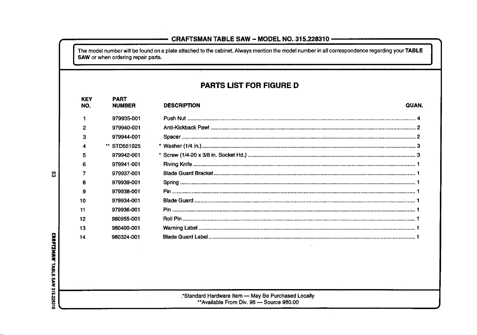
CRAFTSMAN TABLE SAW- MODEL NO. 315.228310
The modelnumberwillbe foundona plateattached tothe cabinet.Always mentionthe modelnumberin allcorrespondenceregardingyourTABLE J
SAW or when orderingrepair parts.
I
ol
€.o
=W
W
111
o
PARTS LIST FOR FIGURE D
KEY PART
NO. NUMBER DESCRIPTION QUAN.
1 979935-001
2 979940-001
3 979944-001
4 ** STD551025
5 979942-001
6 979941-001
7 979937-001
8 979939-001
9 979938-001
10 979934-001
11 979936-001
12 980955-001
13 980400-001
14 980324-001
Push Nut .......................................................................................................................................................... 4
Anti-KickbackPawl .......................................................................................................................................... 2
Spacer .............................................................................................................................................................. 2
Washer (1/4 in.)................................................................................................................................................ 3
Screw (1/4-20 x 3/8 in. SocketHd.) ................................................................................................................. 3
RivingKnife...................................................................................................................................................... 1
BladeGuard Bracket........................................................................................................................................ 1
Spring............................................................................................................................................................... 1
Pin .................................................................................................................................................................... 1
BladeGuard.................................................. :.................................................................................................. 1
Pin .................................................................................................................................................................... 1
RollPin ............................................................................................................................................................. 1
Warning Label.................................................................................................................................................. 1
Blade Guard Label........................................................................................................................................... 1
.*StandardHardware Item-- May Be PumhasedLocally
**Available FromDiv. 98 -- Source980.00
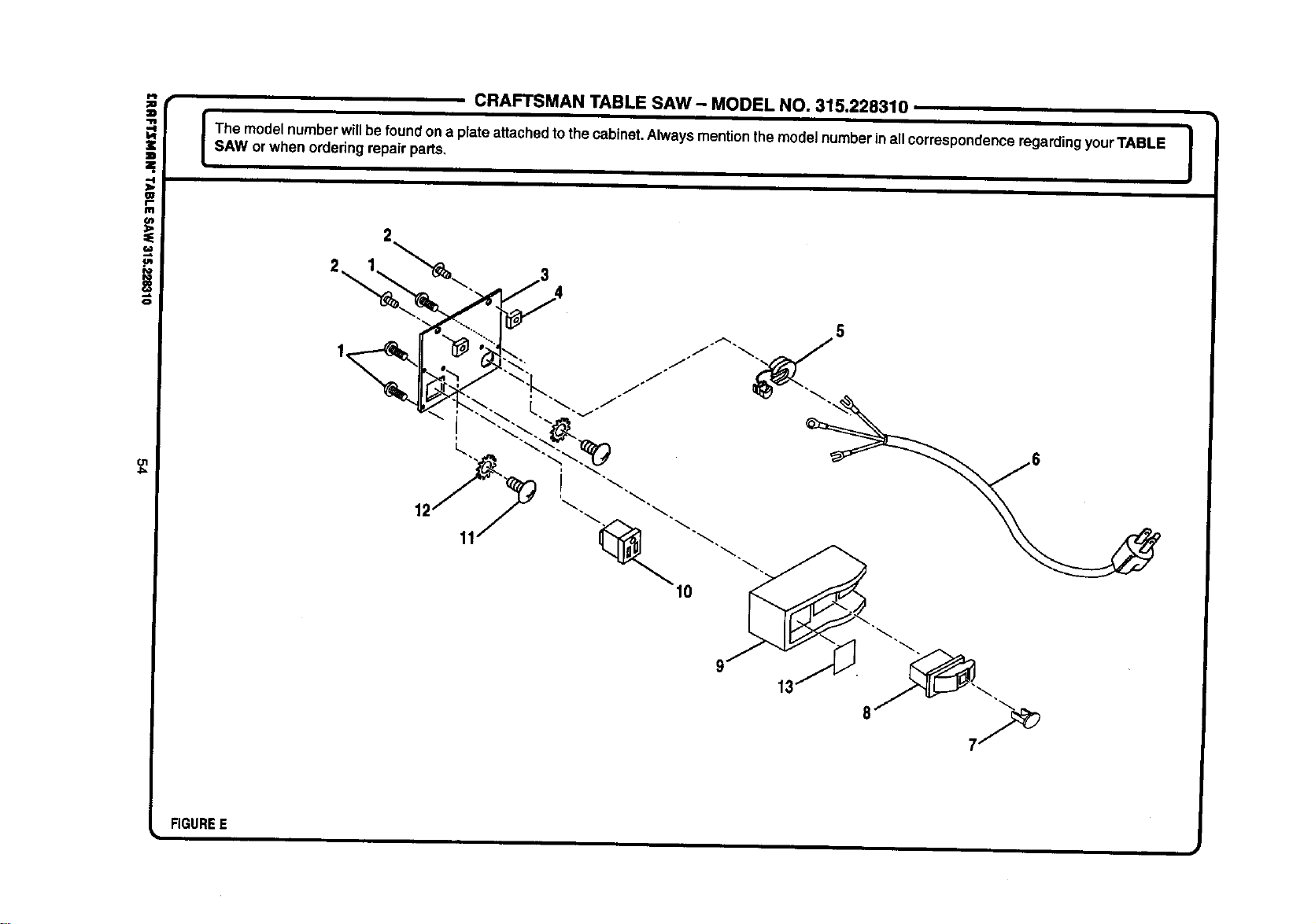
ol
4==
CRAFTSMAN TABLE SAW - MODEL NO. 315.228310
The modelnumberwillbefoundona plate attachedtothe cabinet.Always mentionthe modelnumberin allcorrespondenceregardingyourTABLE I
SAW orwhen orderingrepair parts.
I
11
FIGUREE
i I
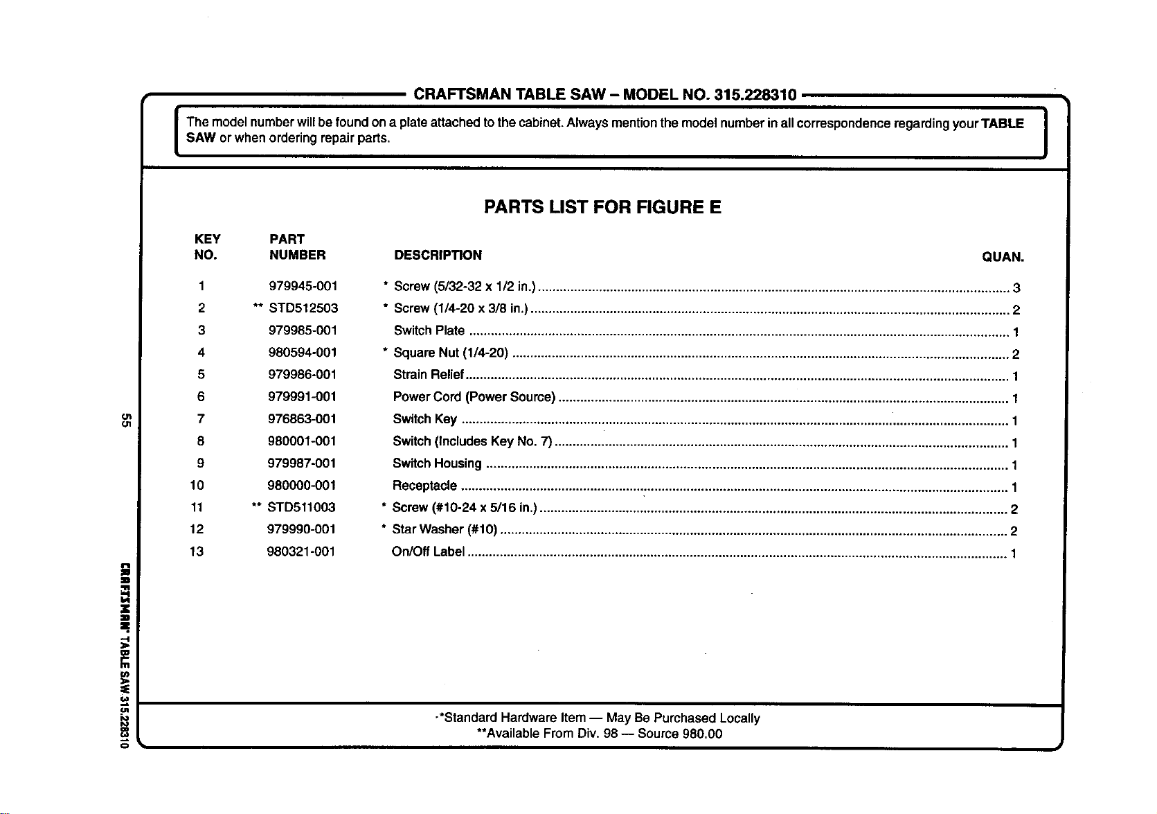
CRAFTSMAN TABLE SAW - MODEL NO. 315.228310
I The modelnumber willbe foundon a plate attachedtothe cabinet.Always mentionthe modelnumberinall correspondenceregardingyourTABLE I
I
SAW or when orderingrepair parts.
I
ot
O1
=.
tJt
o
PARTS LIST FOR FIGURE E
KEY PART
NO. NUMBER DESCRIPTION QUAN.
1 979945-001
2 ** STD512503
3 979985-001
4 980594-001
5 979986-001
6 979991-001
7 976863-001
8 980001-001
9 979987-001
10 980000-001
11 ** STD511003
12 979990-001
13 980321-001
* Screw (5/32-32 x 1/2 in.)................................................................................................................................... 3
* Screw (1/4-20 x 3/8 in.)..................................................................................................................................... 2
Switch Plate ...................................................................................................................................................... 1
* Square Nut (1/4-20) .......................................................................................................................................... 2
StrainRelief....................................................................................................................................................... 1
PowerCord (Power Source)............................................................................................................................. 1
SwitchKey ........................................................................................................................................................ 1
Switch(IncludesKey No. 7) .............................................................................................................................. 1
SwitchHousing ................................................................................................................................................. 1
Receptacle ........................................................................................................................................................ 1
* Screw (#10-24 x 5/16 in.).................................................................................................................................. 2
* StarWasher (#10) ............................................................................................................................................. 2
On/Off Label...................................................................................................................................................... 1
-*Standard Hardware Item-- May Be Purchased Locally
**AvailableFrom Div.98 -- Source 980.00
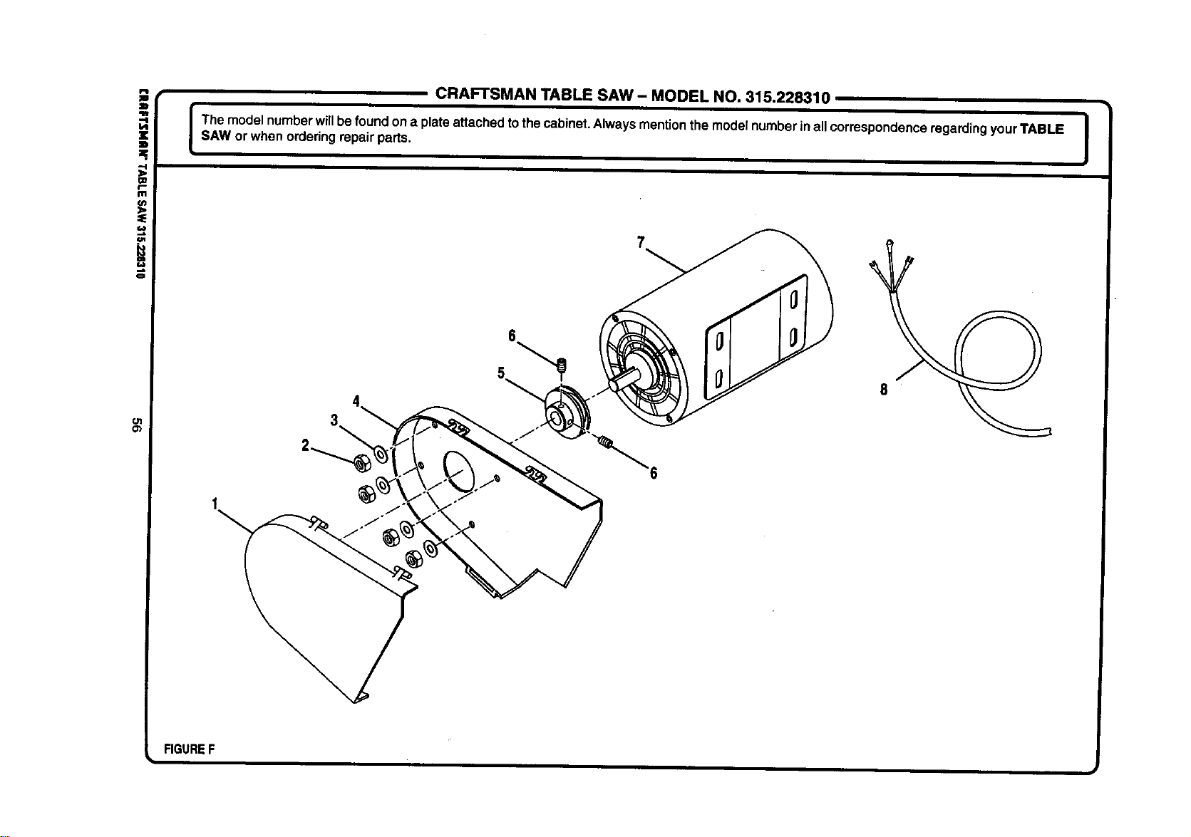
Ol
Cb
CRAFTSMAN TABLE SAW - MODEL NO. 315.228310
I The model numberwillbe foundon a plateattachedto thecabinet.Always mention the modelnumberin allcorrespondenceregarding yourTABLE |
I
SAW or when orderingrepair parts.
I
6
FIGUREF
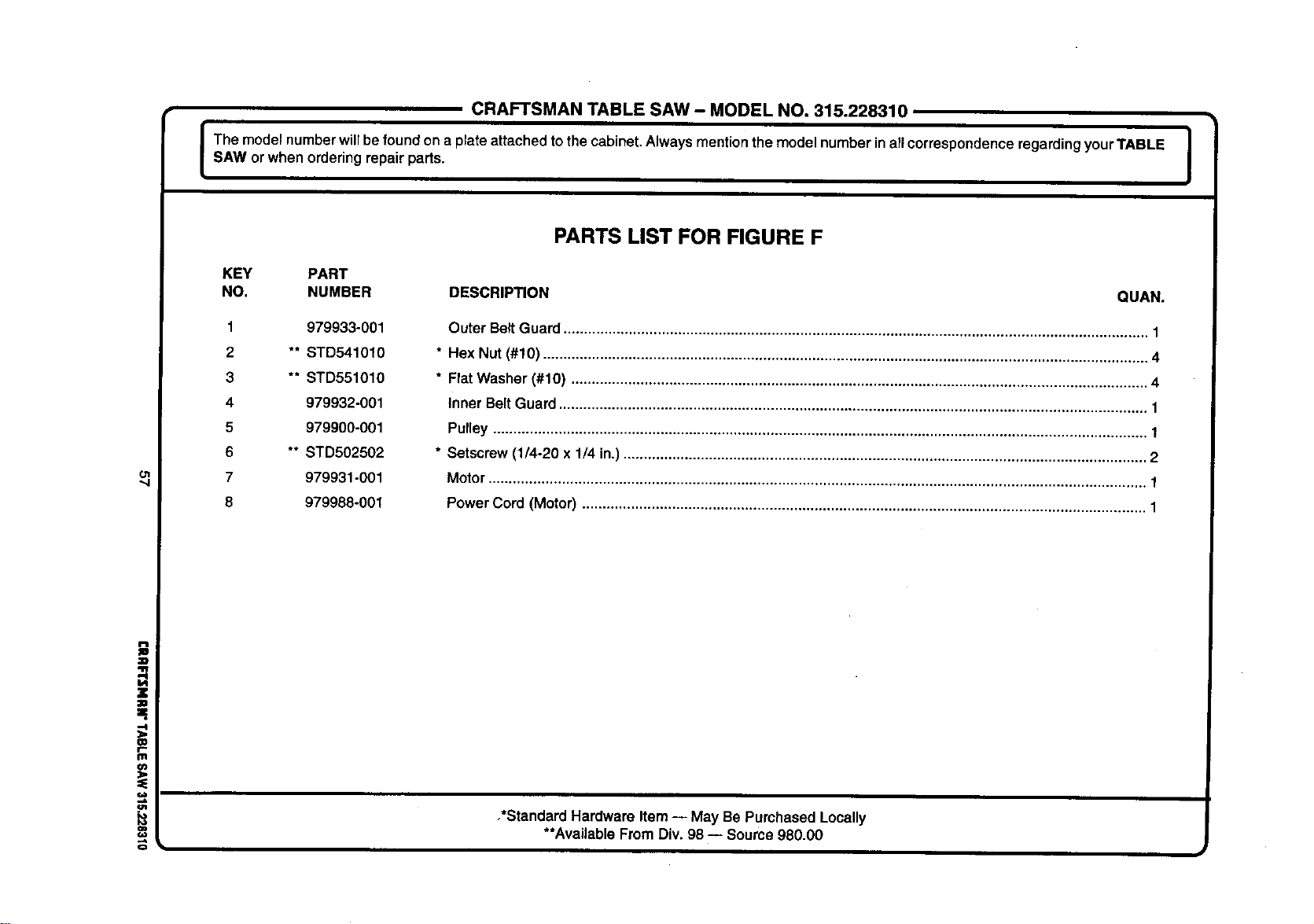
CRAFTSMAN TABLE SAW- MODEL NO. 315.228310
em°0ew °'° ° e °0enum °°c°0°0 0Is,worw ono°e00
ol
W
f,.
m
P_
KEY PART
NO. NUMBER DESCRIPTION
1
2
3
4
5
6
7
8
979933-001
** STD541010
** STD551010
979932-001
979900-001
** STD502502
979931-001
979988-001
PARTS LIST FOR FIGURE F
QUAN.
Outer Belt Guard............................................................................................................................................... 1
* Hex Nut (#10) .................................................................................................................................................... 4
* Flat Washer (#10) ............................................................................................................................................. 4
Inner Belt Guard ................................................................................................................................................ 1
Pulley ................................................................................................................................................................ 1
* Setscrew (1/4-20 x 1/4 in.) ................................................................................................................................ 2
Motor
................................................................................................................................................................. 1
Power Cord (Motor) .......................................................................................................................................... 1
,*Standard Hardware Item-- May Be Purchased Locally
**Available FromDiv. 98 -- Source980.00
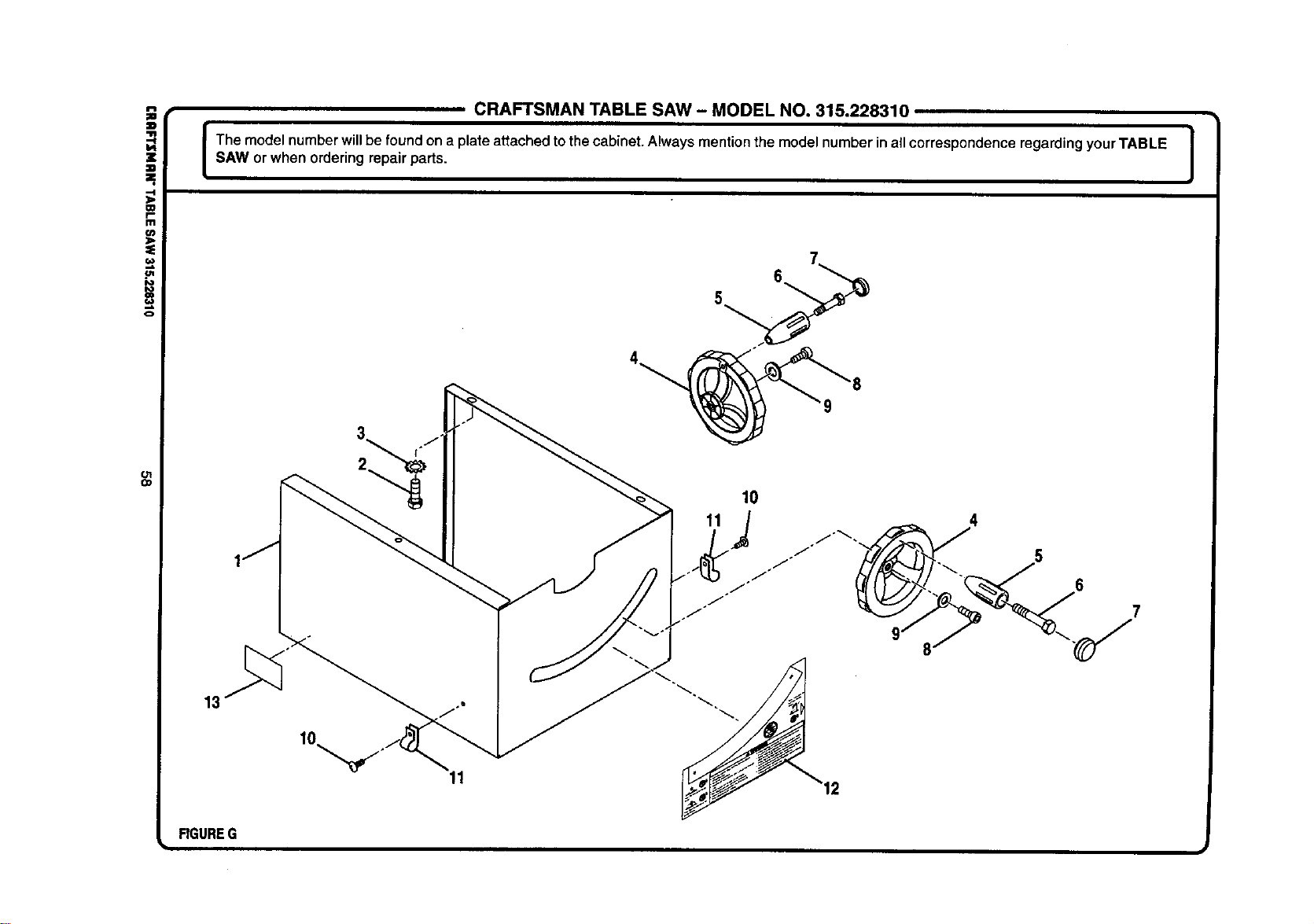
i
o
Ol
O1
CRAFTSMAN TABLE SAW - MODEL NO. 315.228310
The model number willbe found on a plate attached tothe cabinet. Always mention the model number inall correspondence regarding your TABLE |
SAW or when ordering repair parts.
I
17
FIGUREG
11
6
5
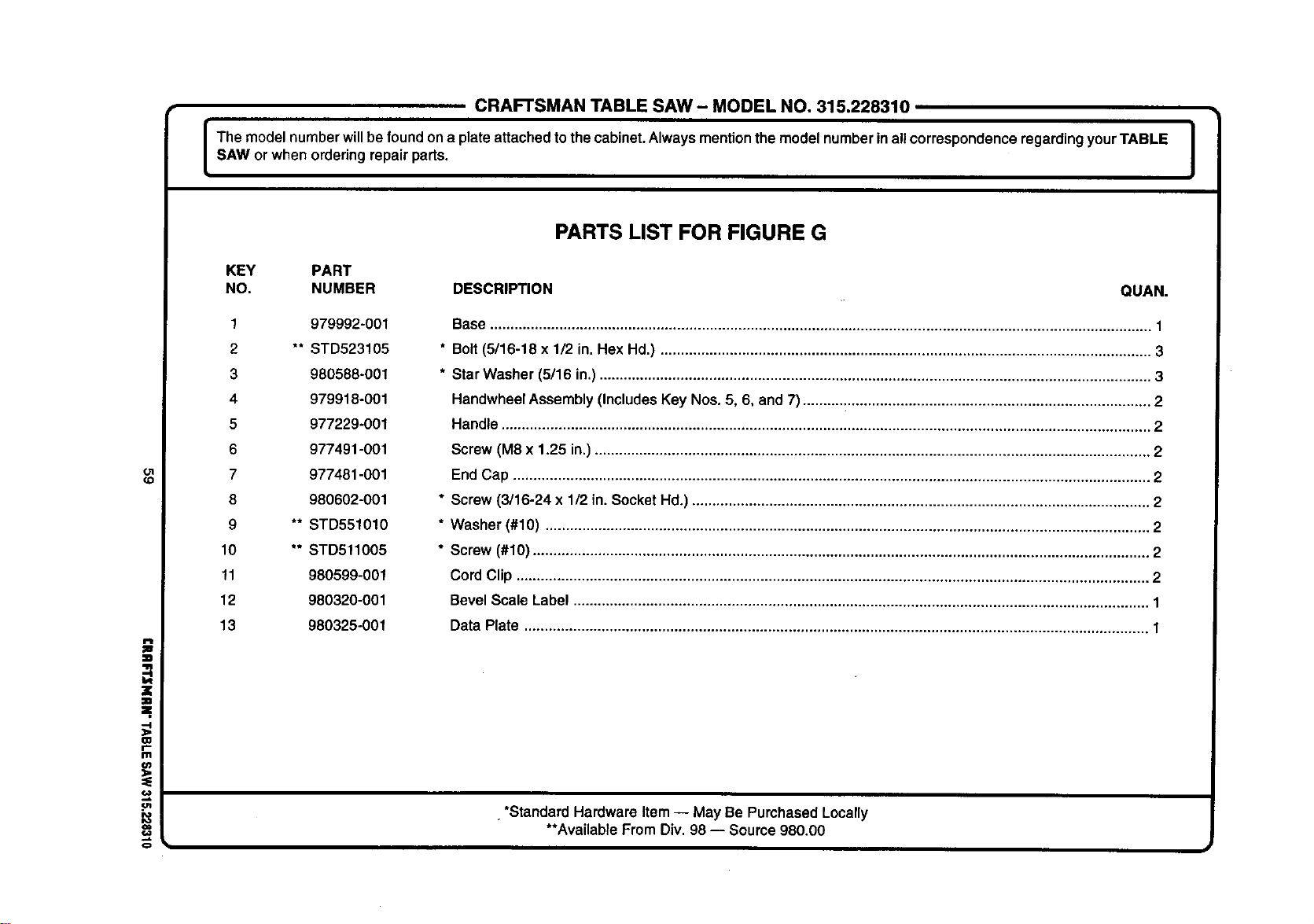
CRAFTSMANTABLESAW- MODELNO.315.228310
The model number willbe foundon a plate attached tothe cabinet.Always mentionthe model numberin allcorrespondenceregardingyourTABLE |
SAW or when orderingrepair parts.
I
Ol
(D
i
=.
CD
r"
Ill
PARTS LIST FOR FIGURE G
KEY PART
NO. NUMBER DESCRIPTION QUAN.
1 979992-001
2 ** STD523105
3 980588-001
4 979918-001
5 977229-001
6 977491-001
7 977481-001
8 980602-001
9 ** STD551010
10 ** STD511005
11 980599-001
12 980320-001
13 980325-001
Base.................................................................................................................................................................. 1
* Bolt (5/16-18 x 1/2 in. Hex Hd.) ........................................................................................................................ 3
* Star Washer (5/16 in.) ....................................................................................................................................... 3
Handwheel Assembly (Includes Key Nos. 5, 6, and 7) ..................................................................................... 2
Handle ............................................................................................................................................................... 2
Screw (M8 x 1.25 in.) ........................................................................................................................................ 2
End Cap ............................................................................................................................................................ 2
* Screw (3/16-24 x 1/2 in.Socket Hd.) ................................................................................................................ 2
* Washer (#10) .................................................................................................................................................... 2
* Screw (#10) ....................................................................................................................................................... 2
Cord Clip ........................................................................................................................................................... 2
Bevel Scale Label ............................................................................................................................................. 1
Data Plate ......................................................................................................................................................... 1
•*Standard Hardware Item-- May Be Purchased Locally
**AvailableFrom Div.98 -- Source 980.00
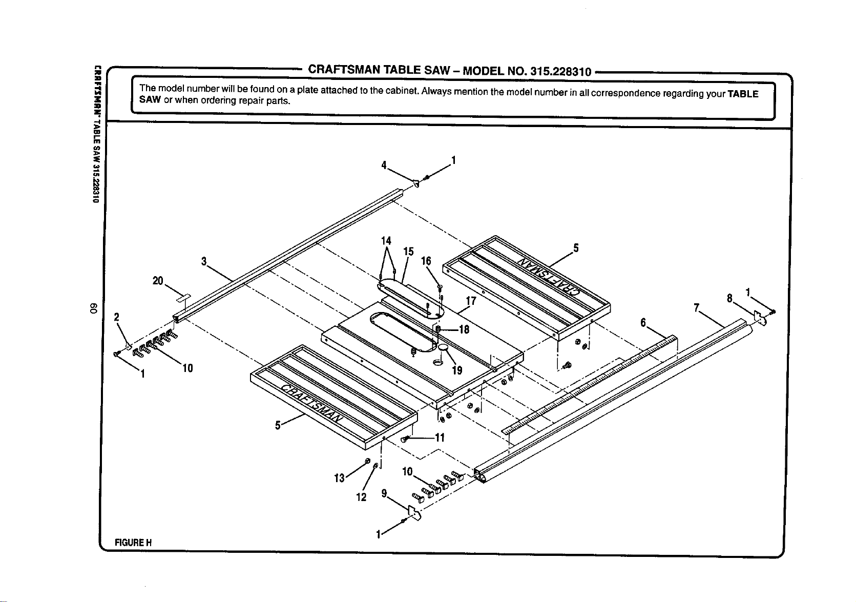
!
¢3
o_
o
CRAFTSMAN TABLE SAW- MODEL NO. 315.228310
I Them_de_numberwi'_bef_und_nap_ateattachedt_thecabinet_A_waysmenti_nthem_de_numberina__c_rresp_ndencer_gardingy_urTABLE_sAwor when orderingrepair parts.
2
FIGUREH
i
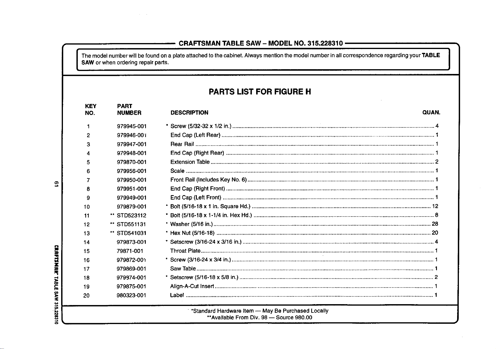
CRAFTSMAN TABLE SAW- MODEL NO. 315.228310
The modelnumberwillbefound on a plateattachedtothecabinet.Always mentionthe modelnumberin allcorrespondenceregardingyourTABLE i
SAW or when orderingrepair parts.
I
i
"4
O_
=E
f.w
io
o
PARTS LIST FOR FIGURE H
KEY PART
NO. NUMBER DESCRIPTION QUAN.
1 979945-001
2 979946-001
3 979947-001
4 979948-001
5 979870-001
6 979956-001
7 979950-001
8 979951-001
9 979949-001
10 979879-001
11 ** STD523112
12 ** STD551131
13 ** STD541031
14 979873-001
15 79871-001
16 979872-00_
17 979869-001
18 979974-001
19 979875-001
20 980323-001
* Screw (5/32-32 x 1/2 in.)................................................................................................................................... 4
End Cap (Left Rear) .......................................................................................................................................... 1
Real Rail ........................................................................................................................................................... 1
End Cap (Right Rear) ....................................................................................................................................... 1
Extension Table ................................................................................................................................................. 2
Scale ................................................................................................................................................................. 1
Front Rail (Includes Key No. 6) ......................................................................................................................... 1
End Cap (Right Front) ....................................................................................................................................... 1
End Cap (Left Front) ......................................................................................................................................... 1
* Bolt (5/16-18 x 1 in. Square Hd.) .................................................................................................................... 12
* Bolt (5/16-18 x 1-1/4 in. Hex Hd.) ..................................................................................................................... 8
* Washer (5/16 in.) ............................................................................................................................................. 28
* Hex Nut (5/16-18) ........................................................................................................................................... 20
* Setscrew (3/16-24 x 3/16 in.)............................................................................................................................ 4
Throat Plate....................................................................................................................................................... 1
* Screw (3/16-24 x 3/4 in.)........................................................... i....................................................................... 1
Saw Table.......................................................................................................................................................... 1
* Setscrew (5/16-18 x 5/8 in.) .............................................................................................................................. 2
Align-A-Cut Insert .............................................................................................................................................. 1
Label ................................................................................................................................................................. 1
• *Standard Hardware Item-- May Be Purchased Locally
**Available From Div. 98 -- Source 980.00
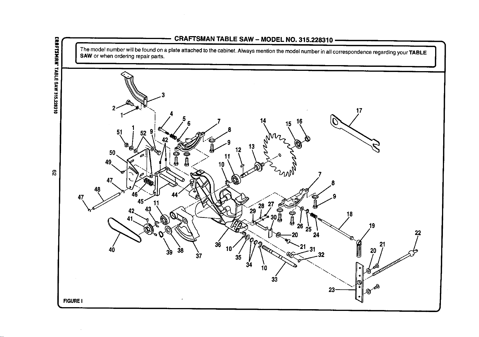
i
(J1
,e.
o
o')
Po
CRAFTSMAN TABLE SAW - MODEL NO. 315.228310
I he model numberwillbefoundon a plate attachedtothecabinet.Alwaysmentionthe modelnumberinall correspondenceregardingyourTABLE I
SAW or when orderingrepairparts.
I
50
1
51
49,
47
48
47
12
1t 15 16
7
17
40
36
38
37
35
34 10
33
IB
19
22
FIGURE I

CRAFTSMAN TABLE SAW - MODEL NO. 315.228310
I The modelnumberwillbe foundon a plate attachedtothecabinet.Alwaysmentionthe modelnumber inall correspondenceregarding yourTABLE I
I
SAW or when ordedngrepair pads.
I
o)
z
II
z
-4
OI
r-
I11
u)
Io
€o
o
KEY PART
NO. NUMBER DESCRIPTION QUAN.
1 ** STD551131
2 ** STD523105
3 979880-001
4 979883-001
5 979884-001
6 980600-001
7 979886-001
8 980588-001
9 980601-001
10 979896-001
11 979895-001
12 979894-001
13 979893-001
14 ***
15 979891-001
16 979890-001
17 979889-001
18 979906-001
19 979907-001
20 979912-001
21 979910-001
22 979917-001
23 979915-001
24 979905-001
25 979904-001
26 979885-001
PARTS LIST FOR FIGURE I
KEY PART
* Lock Washer (5/16 in.) ......................... 6
* Bolt (5/16-18 x 1/2 in. Hex Hd.) ............ 2
Blade Guard Bracket ............................ 1
* Bolt (1/4-20) .......................................... 1
Spdng ................................................... 1
Washer ................................................. 1
Table Bracket ........................................ 2
Star Washer .......................................... 6
* Bolt (5/16-18 x 1 in. Hex Hd.) ............. 10
Retaining Ring ...................................... 3
BallBeadng (8202Z) ............................ 2
Key........................................................ 1
Arbor Shaft ........................................... 1
10 in Blade (Item No. 9 32126) ............ 1
Outer Blade Washer ............................. 1
Blade Nut .............................................. 1
Blade Wrench ....................................... 1
Shaft ..................................................... 1
Bevel Lock Handle ................................ 1
* Washer (5/32 in.) .................................. 5
* Screw (5/32-32 x 3/8 in.) ...................... 5
Threaded Rod ....................................... 1
Bracket .................................................. 1
Spring ................................................... 1
Retaining Ring ...................................... 1
Washer ................................................. 1
NO. NUMBER DESCRIPTION QUAN.
27 ** STD511003
28 980946-001
29 979908-001
30 979911-001
31 979914-001
32 980589-001
33 979924-001
34 979923-001
35 979922-001
36 979897-001
37 979898-001
38 979902-001
39 979903-001
40 979901-001
41 979900-001
42 ** STDS02502
43 980593-001
44 980592-001
45 979925-001
46 979926-001
47 980607-001
48 979927-001
49 979928-001
50 979929-001
51 ** STD541031
62 ** STD441031
972000-524
* Screw(3/16-24 x 3/8 in.) ..................... 2
* Washer (3/16 in.) ................................. 2
Bracket ................................................. 1
Bevel Scale Indicator ........................... 1
Knuckle ................................................ 1
Retaining Ring ..................................... 1
Height Adjustment Rod ........................ 1
Washer ................................................. 2
Washer ................................................. 1
Cradle (Trunnion)................................. 1
Arbor Housing ...................................... 1
Washer ................................................. 1
Retaining Ring ..................................... 1
V-Belt (17-420) ..................................... 1
Pulley ................................................... 1
* Setscrew (1/4-20 x 1/4 in.)................... 4
Retaining Ring ..................................... 1
* Bolt (5/16-18 x 5/8 in. Hex Hd.) ........... 2
Motor Support Base ............................. 1
Spring ................................................... 1
Retaining Ring ..................................... 2
Pivot Shaft ........................................... 1
Screw ................................................... 1
Motor Mounting Plate .......................... 1
* Hex Nut (5/16-18) ................................ 4
* Washer (5/16 in.)................................. 8
Owner's Manual
* Standard Hardware Item -- May Be PurchasedLocally ** Available FromDiv. 98 -- Source980.00
*** Complete AssortmentAvailableAt Your Nearest Sears RetailStore

For in-home major brand repair service:
Call 24 hours a day, 7 days a week
1-800-4-MY-Home s" (1-800-469-4663)
Para pedir servicio de reparaci6n a domicilio - 1-800-676-5811
In Canada for all your service and parts needs call _ 1-800-665-4455
Au Canada pour tout le service ou les pi_ces
For the repair or replacement parts you need:
Call 7 am - 7 pro, 7 days a week
1-800-366-PART (1-800-366-7278)
Para ordenar piezas con entrega a domicilio - 1-800-659-7084
For the location of a Sears Parts and Repair Center in your area:
Call 24 hours a day, 7 days a week
1-800-488-1222
For information on purchasing a Sears Maintenance Agreement
or to inquire about an existing Agreement:
Call 9 am - 5 pro, Monday - Saturday
1-800-827-6655
I
The Service Side of Sears"

