Loading ...
Loading ...
Loading ...
TLW1988N_SVG
HOT
COLD
8
7
6
5
4
3
2
1
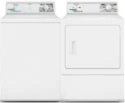
1. Filter Screen (Screen must be facing outward)
2. Fill Hose
3. Rubber Washer (Plain)
4. Cold Water Connection
5. Hot Water Connection
6. Install this end of hose to valve connections at rear of
washer.
7. Install this end of hose to water supply faucet.
8. Faucet
Figure 4
IMPORTANT:
Hoses and other natural rubber parts deteriorate after extended
use. Hoses may develop cracks, blisters or material wear from the
temperature and constant high pressure they are subjected to.
All hoses should be checked on a monthly basis for any visible
signs of deterioration. Any hose showing the signs of deteriora-
tion listed above should be replaced immediately. All hoses
should be replaced every five years.
Connect Drain Hose to Drain Recepta-
cle
1. Remove the drain hose from its shipping position on the rear
of the washer by unhooking the hose from the retainer clamp.
2. Install the drain hose into the drain receptacle (standpipe, wall
or laundry tub) following the instructions below.
NOTE: Drain receptacle must be capable of handling
a minimum of 1-1/4 inch [32 cm] outside diameter
drain hose.
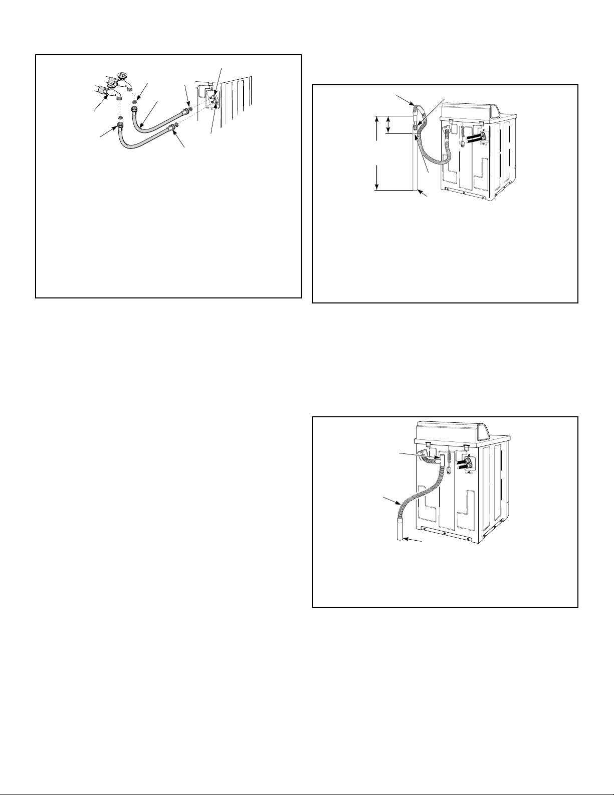
Standpipe Installation
1. Check standpipe height. The recommended height for the
standpipe is 36 inches [914 mm]. Standpipes higher than 4
feet [1220 mm] are not recommended.
2. Place the adapter into the standpipe.
IMPORTANT: To prevent siphoning, do not place
any ribbed portion of the drain hose into the stand-
pipe.
3. Remove the beaded strap from accessories bag and place
around standpipe and drain hose, approximately 12 inches
[300 mm] down from the top of pipe. Refer to Figure 5 .
4. Tighten strap to hold hose to standpipe. This will prevent the
drain hose from dislodging from drain receptacle during use.
TLW1981N_SVG
5
6
4
3
2
1
1. Ribbed Portion of Drain Hose
2. Standpipe Adapter
3. Beaded Strap
4. Standpipe - 2 in. [51mm] or 1-1/2 in. [40 mm] Diameter
5. 36 in. [914 mm] Recommended Height
6. 12 in. [305 mm]
Figure 5
Low Standpipe Installation
If standpipe is lower than 36 inches [914 mm], you must install
No. 562P3 Siphon Break Kit. Refer to Figure 6 . This kit is avail-
able (as optional equipment at extra cost) through an authorized
dealer or parts distributor. Installation instructions are supplied
with the kit.
W512I_SVG
2
1
3
1. 562P3 Siphon Break Kit
2. Standpipe
3. Drain Hose
Figure 6
Wall Installation
For installations of this type, the drain hose MUST be secured to
one of the fill hoses using the beaded strap from accessories bag.
Refer to Figure 7 .
NOTE: End of drain hose must not be below height of
cabinet top.
Installation
Part No. 203174
©
Copyright, Alliance Laundry Systems LLC - DO NOT COPY or TRANSMIT 7
Loading ...
Loading ...
Loading ...