Indoor Unit Operation & Installation Manual
MVAW007MV2AA
MVAW009MV2AA
MVAW012MV2AA
MVAW018MV2AA
MVAW024MV2AA
MVAW030MV2AA
No. 0150522200
• Please read this manual carefully before using.
• Keep this operation manual for future reference.
Original instructions
CONTENTS
Parts and Functions...........................................................................................................................................................1
Safety ................................................................................................................................................................................2
Emergency Running & Test operation ............................................................................................................................... 5
Maintenance ...................................................................................................................................................................... 6
Fault Checkup ...................................................................................................................................................................7
Installation Procedures ...................................................................................................................................................... 8
Electrical Wiring ...............................................................................................................................................................13
Test Run & Failure Code .................................................................................................................................................17
Your air conditioner may be subject to any change owing to the improvement of Haier products.
MRV series multi zone air conditioning systems can operate multiple indoor units in heating or cooling. When in cooling,
only units set to cool will run. Same logic applies for heating.
Turn power on for 12 hours prior to start-up to allow the crankcase heater adequate time to protect the compressor. All
indoor units on the same refrigeration system should use the unied power switch to ensure that all indoor units are all
powered on during system operation.
Product Features
1.Hanging-style installation to save space;
2.Automatic display of faults;
3.Function of central control, wired control,wireless control (optional from our company).
4.The air conditioner is provided with the function of compensation for power supply. During operation, when the power
supply fails emergently and resumes again, the air conditioner returns to the working condition before power failure, if
provided with compensation function.
5.The operating methods and functions are same although the shapes of indoor units are different. Therefore, the outline
drawing of MVAW007MV2AA indoor unit is taken as an example for illustration.
User Manual
Operation condition:
To use the air conditioner normally, please perform as to the below conditions.
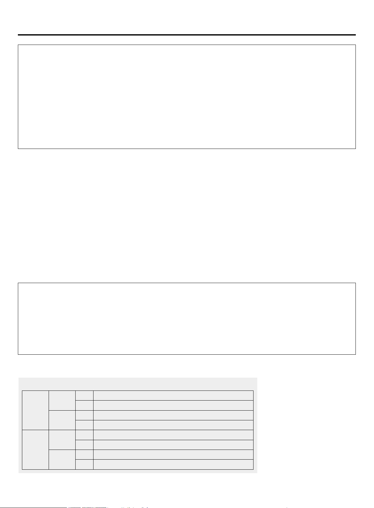
Operating Range of Air Conditioner
Cooling
dry
Indoor
Max. DB: 90°F(32°C) WB: 74°F(23°C)
Min. DB: 64°F(18°C) WB: 57°F(14°C)
Outdoor
Max. DB: 115°F(46°C) WB: 79°F(26°C)
Min. DB: 23°F(-5°C)
Heating
Indoor
Max. DB: 80°F(27°C)
Min. DB: 59°F(15°C)
Outdoor
Max. DB: 75°F(24°C) WB: 59°F(15°C)
Min. DB: -4°F(-20°C)
Warning
•
I
f the supply cord is damaged, it must be replaced by the manufacturer, its service agent or similarly qualied persons
in order to avoid a hazard.
•
T
his equipment should not be used or serviced by personnel who have not been properly trained in its operation and
maintenance.
•
C
hildren should be supervised to ensure that they do not play with the appliance.
•
T
he appliances are not intended to be operated by means of an external timer or separate remote-control system.
•
K
eep the appliance and its cord out of reach of children less than 8 years.
1
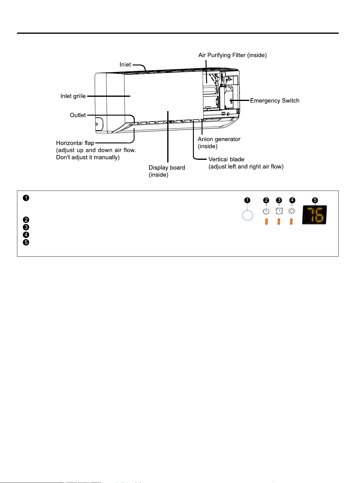
Parts and Functions
Indoor Unit
Remote signal receiver
(A beeping sound is generated when a signal from
remote controller isreceived.)
Power indicator (Lights up when unit starts.)
Timer mode indicator (Lights up whenTimer operation is selected.)
Operation mode indicator (lights up when the compressor is on.)
Ambient temp display
When receiving the remote control signal, display the set temperature.
2
• This manual should be saved and stored close to this air conditioning equipment.
• There are two types if indications. Both are related to safety and should be strictly followed. "
Warning" highlights
issues that pose a risk of major injury or death. "
Caution" highlights issues that pose a risk of equipment or bodily
injury.
• After installation and start-up commissioning, please give the manual to the user. The manual should be kept in safe
place and close to the unit.
• Installation and maintenance should be performed by an authorized agency. The wrong operation of this air condition
equipment may cause water damage, electric shock or re.
• Please install the unit on the top of a solid foundation or structure which is strong enough to support the unit.
• The installation of this condition equipment should follow local building codes.
• Use the right cable size, secure the terminal rmly, organize the cables well and make sure no tension is added on
cables. Cable insulation should not be damaged. Improper wire installation may lead to re.
• This unit is only compatible with R-410A refrigerant. If any other gas enters the system, it may lead to abnormal high
pressure which may cause damage or injury.
• Only use branches supplied by Haier. Use of any other branches will void warranty.
• Keep the condensate drain pipe away from toxic gas vents to prevent possible pollution of indoor environment.
• Care should be taken to ensure that there are no refrigerant leaks. R-410A is a heavy gas and will displace oxygen.
Ventilate the area if a leak if found.
• The unit is not explosion-proof. Please keep it away from ammable gases.
• The drain pipe should be installed per this manual to ensure proper drainage. The pipe should be well insulated to avoid
condensation. Wrong installation may lead to water damage.
• Both liquid pipe and the vapor pipe should be also well insulated. Not enough insulation may lead to system
performance deterioration or condensate formation.
• This equipment should not be used or serviced by personnel who have not been properly trained in its operation and
maintenance.
• Children should be supervised to ensure that they do not play on or near the equipment.
• Keep the appliance and its cord out of reach of children.
• The appliances are not intended to be operated by means of an external timer or separate remote-control system.
Safety
WARNING
• Grounding wire should be connected to the grounding bar. The grounding wire cannot be connected to the gas pipe,
water pipe, lightening rod or the telephone grounding wire. Improper grounding may cause electric shock.
• A circuit breaker should be installed. If not, it may cause electric shocks or accidents.
• After installation, the air condition equipment should be powered on and passed the electric leakage current lest.
• If the ambient humidity is more than 80%, if the water discharge hole is blocked or the lter becomes dirty or the airow
speed changes, this may lead to condensate water leaks. There may also be some drops of water spraying out.
CAUTION
3
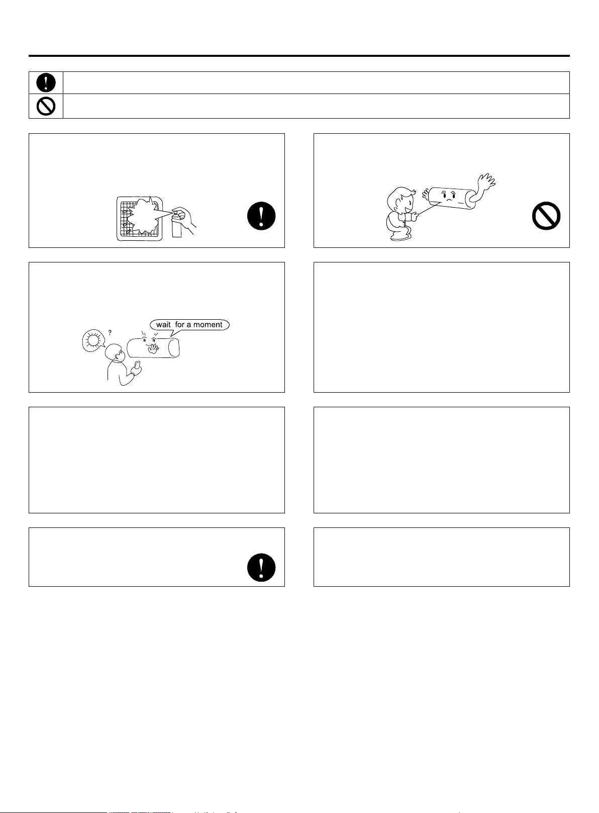
Safety
Items with this warning sign concerning the product’s safety and the personal security must be performed strictly.
Items with this forbidding sign refer to absolutely forbidden behaviors. If not, they may cause machine damage or
endanger operator’s personal safety.
Regulating Wind Direction:
It is recommended not to make the wind deector
downwards for a long time to avoid condensation at
air outlet port during refrigerating or dehumidifying.
Water dropping might appear at the air outlet port in
refrigerating or dehumidifying mode.
Defrosting:
During heating running, the air conditioner would
defrost automatically if there is frost on heat
exchanger of outdoor units.
Do not rotate fans of both indoor units and outdoor
units during defrosting.
After nishing defrosting, the air conditioner will
resume running automatically.
The machine operation must be controlled by the
control.
Hints:
As air conditioners absorb heat from the environment
and release it to the room, heating effects will be
inuenced by the temperature in and out of the room.
Clean the lter regularly.
Cooling or heating performance will be degraded if the
lter is blocked, resulting in large power consumption,
failure, and water dripping at freezing.
Don’t touch the outlet while the ap is moving. Don’t
put anything in the grid in case danger may occur.
Avoid cold wind from blowing out.
During heating running, the fan of indoor units will
not rotate immediately as to prevent cold wind from
blowing out.
Changing Wind Speeds:
In the state of refrigerating, with automatic blowing
mode, the wind speed automatically decreases when
the room temperature approaches the setting.
In the state of heating, when the room temperature
reaches the setting temperature the compressor stops
working and the fan turns to low wind or stops. Wind
speed changes automatically in the dehumidifying
mode.
4
Safety
Attention
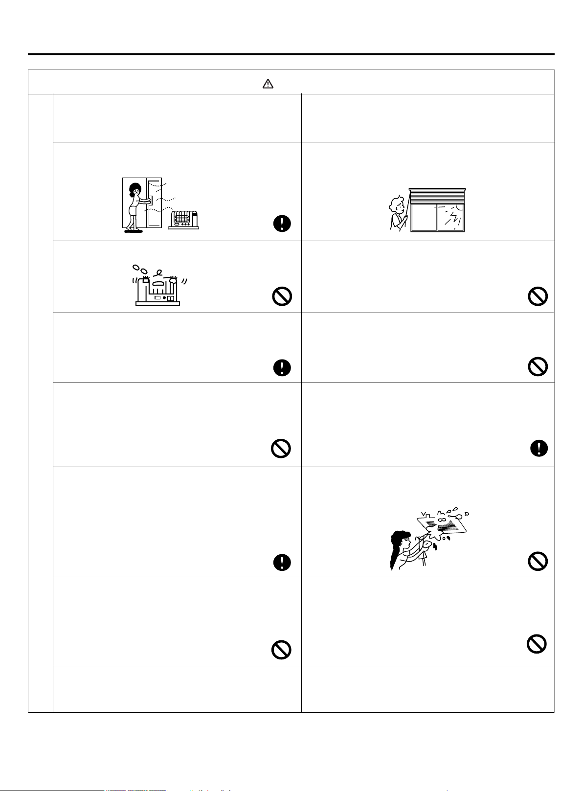
• Do not put any heating apparatus under the
indoor units. The heat may cause distortion of the
units.
• Pay attention to the ventilation to avoid anoxic injury.
• Do not place an open ame in the path of blowing air.
• Do not install in a corrosive environment. If the base
collapses, the unit may fall and cause damage,
product failure, personal injury or death.
• Do not use the unit for special purposes such
as preserving foods, works of art etc. It is an air
conditioner for comfort cooling / heating, not a
precision refrigeration system.
• Use the correctly rated breaker or fuse. Improper
breaker or fuse may lead to re, electric shock,
explosion, personal injury or death.
• Turn off the power to save energy if the unit will
be not used for a long period. If the unit is not
powered off, it will consume power.
• Do not permit water or steam to enter the unit and
the wired controller. There is risk of unit failure, re,
electric shock, personal injury or death.
• 3-minutes protection
To protect the unit, there is a 3-minute time-out after
the unit stops or after power is applied.
• Close the window to avoid outdoor air getting in.
Curtains or window shutters can be put down to avoid
the sunshine.
• Do not touch the power switch with the wet hand to
avoid power shock.
• Turn off the system and remove power when servicing
the unit.
• Don't remove power while system is running.
• Do not clean the unit with water spray. There is risk
of unit failure, re, electric shock, personal injury or
death.
• Keep ammable gas or combustibles away from the
unit. There is risk of product failure, re, personal
injury or death.
• Please keep children away from this air condition
equipment.
Notices during Operation
5
Emergency Running & Test operation
Emergency Running & Test operation:
• Emergency running will help air conditioner operate automatically if your remote control is missing or out of work.
• Test operation is recommended when room temperature is below 60.8*(16*) but not in normal condition.
Emergency Running
It is recommended to use only when the remote control is missing or damaged.
Temperature setting values and wind speed cannot be changed in the mode of emergency running.
Meanwhile, dehumidication and timing operation cannot be operated simultaneously.
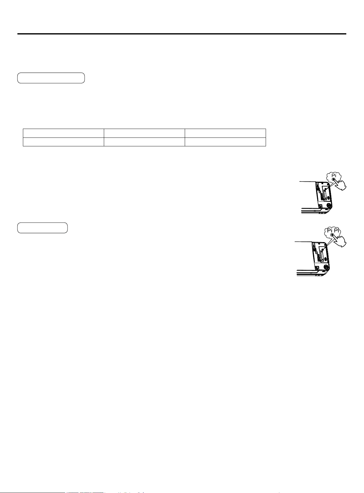
Startup
A warning tone could be heard after turning on the Emergency Running switch,which means that the emergency running
gets started.
• Air conditioner operates automatically according to the working modes blow:
Set Temp Wind Speed Working Mode
75.2°F(24°C) auto auto
Shutdown (canceling the emergency running)
All the indicator lamps on the conditioner extinguish after pressing the emergency running switch and
hearing the warning tone.
Canceling the emergency running with the remote controller
A warning tone is heard after pressing the ON/OFF button on remote controller. The air conditioner
works according to the indication of operating state on the remote controller.
Test Operation
It is recommended when the room temperature is below 60.8°F (16°C) but not in normal condition.
Startup
Press it for over 5 seconds till 2 warning tones are heard and then release your nger to start the
test operation. The air conditioner is operating at high wind speed. The test operation lasts for 30
minutes before the air conditioner stops automatically.
Shutdown (canceling the test operation)
The warning tones are followed after pressing the test operation switch.
Canceling the test operation with the remote controller
The warning tone could be heard after pressing the switch on remote controller.
The air conditioner works according to the indication of operating state on the remote controller.
6
Cleaning the air lter & air inlet grid.
• Don't remove the air lter except for cleaning, or faults may occur.
• When the air conditioner operates in the environment with too much dust, clean the air lter on a more regular basis
(generally once every two weeks).
Maintenance
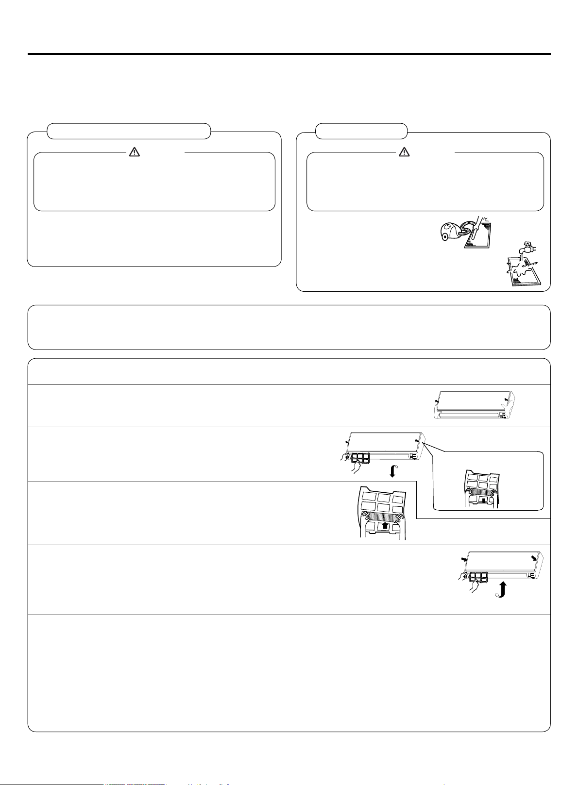
Cleaning the Air Inlet/Outlet Grilles:
• Do not use gasoline, benzene, diluents, polishing
powder or liquid insecticide to clean them.
• Do not clean them with hot water of over
122°F(50°C) to avoid fading or distorting.
Attention
• Wipe them with a soft dry cloth.
• Water or neutral dry cleaner is recommended if the
dust cannot be removed.
(A) Brush off dirt and vacuum.
(B) Wash with soft cloth and mild detergent.
(C) Shake water off and allow the lter to
fully air dry before reinstalling.
Cleaning Air Filter:
• Don't rinse the air lter with hot water of above
122
ºF(
50°C) to avoid fading and distorting.
• Don't put the air cleaner near re to dry to avoid
catching re.
Attention
Clean the machine (Cleaning ways are approximately same, taking MVAW007MV2AA indoor machine as example).
Turn off the air conditioner before cleaning. Do not touch the machine if the hands are wet. Neither hot water nor
solvent should be used in cleaning.
Replacement of Air Purifying Filter
1.Open the lnlet Grille
Prop up the inlet grille by using a small device named grille-support which
located in the right side of the indoor unit.
2.Detach the standard air lter
Slide the knob slightly upward to release the lter, then withdraw it.
Detach old Air Purifying Filter
3.Attach Air Purifying Filter
Put air purifying lter appliances into the right and left lter frames.
5.Close the Inlet Grille
Close the Grille surely
4.Attach the standard air lter (Necessary installation)
ATTENTION:
The white side of the photocatalyst air purifying lter face outside,and the black side face the
unit The green side of the bacteria-killing medium air purifying lter face outside,and the white side face the unit.
NOTE:
• The photocatalyst air purifying lter will be solarized in xed time. In normal family, it will be solarized every 6 months.
• The bacteria-killing medium air purifying lter will be used for a long time,no need for replacement. But in the period
of using them ,you should remove the dust frequently by using vacuum cleaner or aping them lightly, otherwise, its
performance will be affected.
• Please keep the bacteria-killing medium air purifying lter in the cool and dry conditions avoid long time directly
sunshine when you stop using it,or its ability of sterilization will be reduced.
7
Fault Checkup
Please check the following when consigning repair service:
All these are not problems
Symptoms Reasons
Water ow sound
Water ow sound can be heard when starting operation, during operation or
immediately after stopping operation. When it starts to work for 2-3 minutes,
the sound may become louder, which is the owing sound of refrigerant or
the draining sound of condensed water.
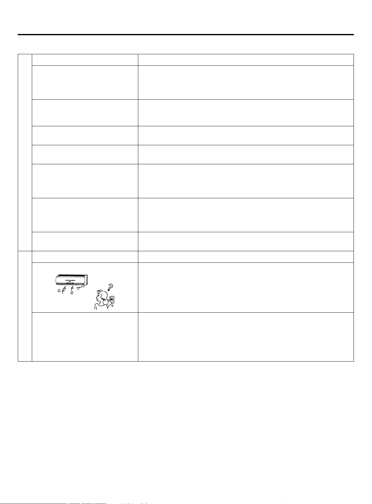
Cracking sound
During operation, the air conditioner may make the cracking sound, which
is caused from the temperature changes or the slight dilation of heat
exchanger.
Terrible smell in outlet air
The terrible smell, caused from walls, carpet, furniture, clothing, cigarette
and cosmetics, attaches on the conditioner.
Flashing operating indicator
When switching it on again after power failure, turn on the manual power
switch and the operating indicator ashes.
Awaiting indication
It displays the awaiting indication as it fails to perform refrigerating operation
while other indoor units are in heating operation. When the operator set it
to the refrigerating or heating mode and the operation is opposite to the
setting, it displays the awaiting indication.
Idle indoor unit still has sound of
refrigerant owing and radiating
temperatures.
To prevent oil and refrigerant from blocking the valve of idle units (off or
satised) while other indoor units are operating, some refrigerant ow is
allowed to pass through. This may result in some radiating temperature and
ow noise.
Clicking sound when unit comes on.
When the conditioner is powered on, the sound is made due to the resetting
of the expansion valve.
Please make another check.
Start or stop working automatically Check if it is in the state of Timer-ON and Timer-OFF.
Failure to work
Check if there is a power failure.
Check if the supply fuse and breaker are disconnected.
Check if the unit is displaying any faults.
Check if wait symbol is displayed. This is due to other indoor units
connected to the same outdoor unit are running in the opposite mode.
System cannot heat and cool simultaneously.
• Bad cooling & heating effects
Check if air intake port and air outlet port of outdoor units are blocked.
Check if the door and windows are open.
Check if the ltering screen of air cleaner is blocked with sludge or dust.
Check if the setting of wind quantity is at low wind.
Check if the setting of operation is at the Fan Operation state.
Check if the temperature setting is proper.
Under the following circumstances, immediately stop the operation, disconnect the manual supply switch and contact the
after-service personnel.
• When buttons are inexible actuated;
• When fuse and breaker have been burnt over and over;
• When there are foreign objects and water in the refrigerator;
• When it cannot still be operated after removing the operation of protective unit;
• When other abnormal conditions occur.

8
This manual cannot completely illustrate all the properties of the products you bought. Please contact the local Haier
distribution center if you have any question or request.
Please use the standard tool according to the installation requirements.
The standard attached accessories of the units of this series refer to the packing; prepare other accessories according to
the requirements of the local installation point of our company.
1. Choose the suitable installation location. Indoor units should be installed in places with the environment of
even circulation of cool and warm blows. The following places should be avoided.
Places with high salinity (beach), high sulfureted gas(such as the thermal spring regions where copper tubes and soft
soldering are easy to be eroded), much oil(including mechanical oil) and steam; places where organic substance solvent
is frequently used; places where machines generate the high frequency electromagnetic wave (abnormal condition will
appear in the control system); places where there is high humidity exists near the door or windows (dew is easily formed);
and places where the special sprayer is frequently used.
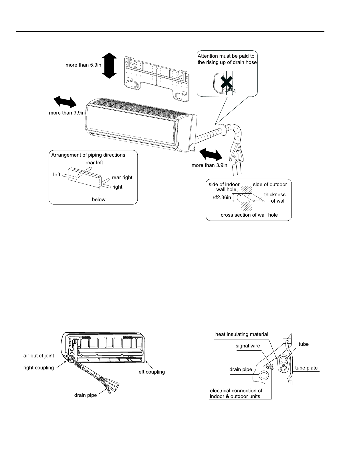
Installation Procedures
1. The distance between wind outlet port and the ground should not
be more than 8.86ft. The distance to streets should not be less
than 8.2ft.
2. Select appropriate places for installation where the outlet air
can be spread to places all over the house and arrange proper
locations for connecting pipes and lines as well as the drainpipe
to the outdoor.
3. Ceiling construction must be hard enough to hold the weight of
the unit.
4. Make sure that the connecting pipe, drainpipe and connecting
guide line can be put into walls to connect the outdoor units.
5. It is recommended to make the connecting pipe between the
outdoor and indoor units and the drainpipe are as short as
possible.
6. Please read the attached installation instruction of outdoor units
for regulation of lling amount of refrigerant if necessary.
7. Select a place close to the supply socket of air conditioner and
enough space should be kept near the machine.
8. Those electrical appliances such as television, instruments,
devices, artwork, piano, wireless equipment and other valuables
should not be placed under the indoor unit and over 1m away
from the daylight lamp as to prevent condensate from dropping
into them and causing damage.
Indoor Units
Required Tools for Installation
• Brazing torch
• 15% silver phosphorous copper brazing alloy
• Wire stripper
• Soap-and-water solution or gas leakage
detector
• Torque wrench
• 17mm, 22mm, 26mm
• Tubing cutter
• Reaming tool
• Flaring tool
• Razor knife
• Measuring tape
• Level
• Vacuum pump
• Micron gauge
• Nitrogen
• Mini-Split AD-87 Adapter (1/4” to 5/16”)
• Non-adhesive Tape
• Adhesive Tape
• Electrical wiring
2. The following steps can be taken after selecting the installation place:
Cut a hole on the wall and put the connecting pipe and connecting thread into the PVC, which is purchased at the local
shop. With a slight downwards tilt towards the exterior, the gradient should be kept at least 1/100. before cutting the hole,
check if there are pipes or reinforcing steel bars at the rear of the hole. Making the hole in the place with wires or pipes
should be avoided.
9
Installation Procedures
3.Installation Drawing of Indoor Units:
(1) Positioning Wall Pad & Locating Wall Holes
Fix the pad according to the installation location and the pipe layout of indoor unit (please refer to the installation drawing).
Installation should be done under the crossbeam or on the at wall near the pillar. First x the pad with a steel nail on the
wall.
Drop a thread with a bolt through the pad center or use a level meter to nd the level.
Then x it with a concrete steel nail, and measure the position of the wall hole A.
(2) Drilling Hole & Mounting Guard Ring
Drill a hole of 2.36in bore with a slight tilt downwards to the outside, mount the guard ring, and seal it with gesso or putty
after nishing the installation.
(3) Arranging Wiring of Indoor Unit
Arrange the layout of connection pipe, drain pipe, connecting line, signal line and air refreshing pipe according to the
locations of your indoor unit, outdoor unit and wall holes, with drainage hose lower, connecting line upper. Intercrossing
winding is not allowed between the mains line and the connecting line, and the drain pipe(especially in the indoor unit and
the inside of machine) should be winded with heat insulating materials for heat preservation.
(4) Lead the connection tubing(liquid pipe and gas pipe) through the hole into the wall, or connect piping and wiring of
indoor unit(check the number of wiring terminals of indoor and outdoor units and connect terminals with the same number
and color), and then put the connection tubing and the connecting line through from the inside wall for the connection with
outdoor unit.
10
Installation Procedures
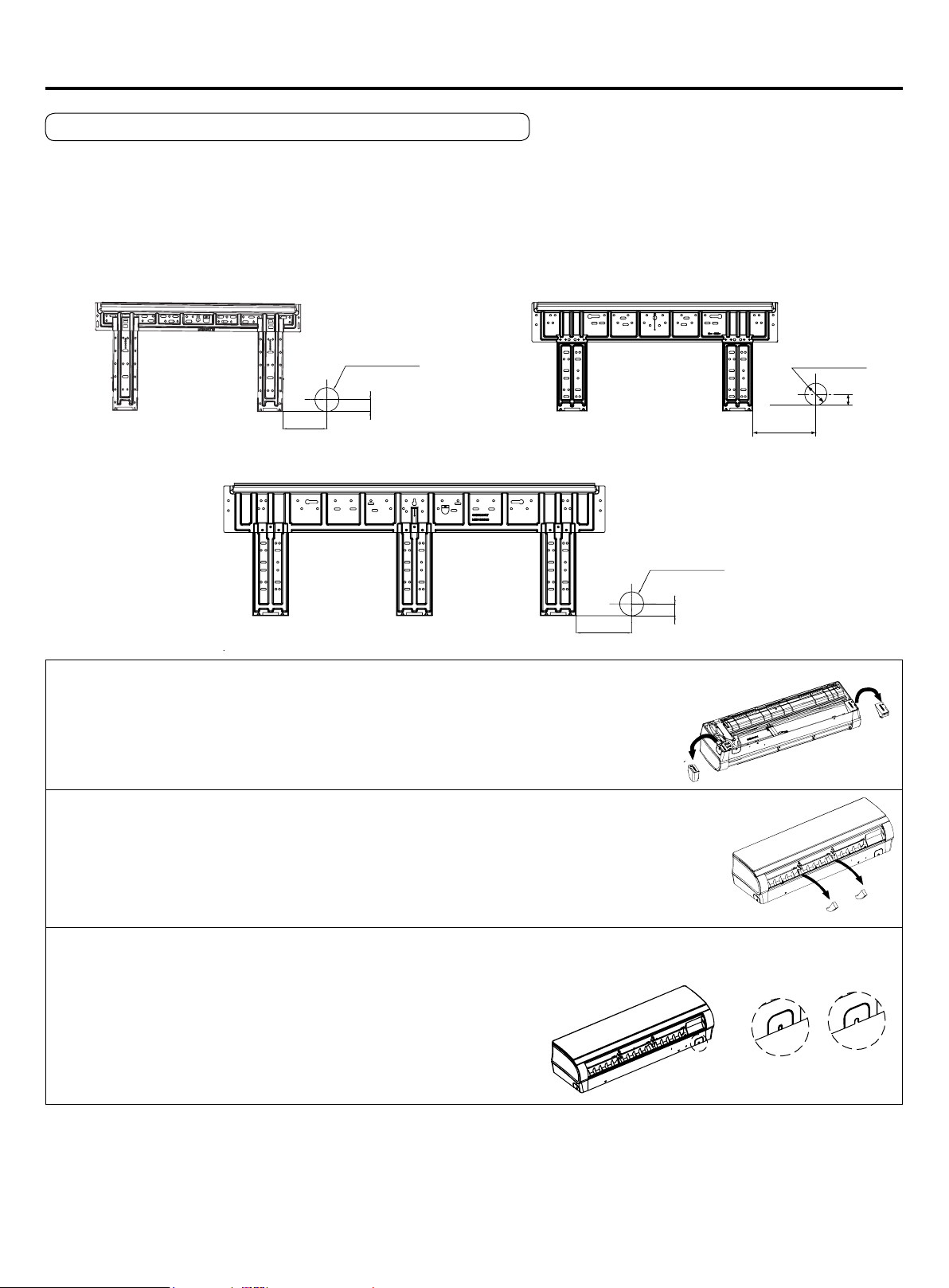
Fitting of the Mounting Plate and Positioning of the wall Hole
When the mounting plate is rst xed
1. Carry out, based on the neighboring pillars or lintels, a proper leveling for the plate to be xed against the wall, then
temporarily fasten the plate with one steel nail.
2. Make sure once more the proper level of the plate, by hanging a thread with a weight from the central top of the plate,
then fasten securely the plate with the attachment steel nail.
3. Find the wall hole location A using a measuring tape.
MVAW018~024MV2AA
A=4.92in
B=Ø2.36in
1.18in
MVAW007~012MV2AA
A=2.99in
B=Ø2.36in
1.18in
A=5.5in
B=Ø2.36in
1.18in
MVAW030MV2AA
Pay attention to the following points before installation of machine:
1. Take out cushion blocks on the left and right angle beads as shown in the following Figure.
2. Remove 2 gaskets under the cross-ow fan (MVAW018/24MV2AA).
3. Clean the burr on the surface of fracture to avoid the power wire from being scratched after removing the virtual
opening of the outgoing line slot on the case by hands in indoor power-on process.
When the mounting plate is xed side bar and lintel
• Fix to side bar and lintel a mounting bar, Which is separately sold, and then fasten the plate to the xed mounting bar.
• Refer to the previous article, "When the mounting plate is rst xed" for the position of wall hole.
11
Installation Procedures
Pipe Length & Height Difference
Please refer to the attached manual of outdoor units.
Model MVAW007~018 MVAW024~030
Tubing Size
in(mm)
Gas pipe Ø1/2"(Ø12.7) Ø5/8"(Ø15.88)
Liquid pipe Ø1/4"(Ø6.35) Ø3/8"(Ø9.52)
Tubing Material Seamless copper pipe rated for R410A refrigerant
Tubing Materials & Specications
Add the refrigerant according to the installation instruction of outdoor unit. The addition of R410A refrigerant must be
performed with a digital scale to ensure the proper charge. Compressor failure can be caused by over or under charging
the system.
Refrigerant Recharge Amount
Proceed the are tube connecting operation to connect all the refrigerant tubes.
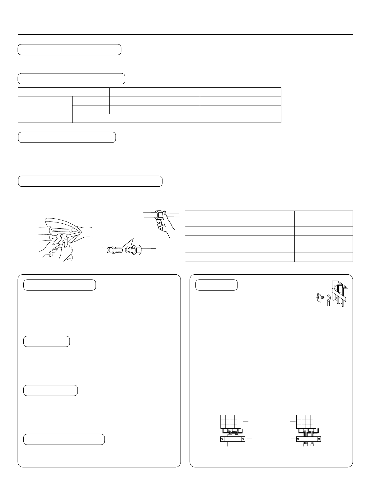
Connecting Procedures of Refrigerant Tubing
• Dual wrenches must be used in the connection of indoor unit tubing.
• Mounting torque refers to the right table
Outer Diameter of
Tubing in (mm)
Mounting Torque
lb-in (N-m)
Flare Torque Spec
ft-lb (N-m)
Ø1/4"(Ø6.35) 104.4 (11.8) 13 (18)
Ø3/8"(Ø9.52) 216.8 (24.5) 30 (40)
Ø1/2"(Ø12.7) 443.7 (49.0) 43 (59)
Ø5/8"(Ø15.88) 693.9 (78.4) 76 (103)
refrigerant oil
joint nut
wrench wrench
Cutting or enlarging pipes should be proceeded by
installation personnel according to the operating
criterion if the tube is too long or are opening is
broken.
Cutting and Enlarging
1. Connecting circular terminals:
The connecting method of
circular terminal is shown in the Fig. Take off the screw,
connect it to the terminal tier after heading it through
the ring at the end of the lead and then tighten it.
Connecting
Vacuumize from the stop valve of outdoor units with
vacuum pump. Refrigerant sealed in indoor machine is
not allowed to use for vacuumization.
Vacuumizing
Open all the valves of outdoor units. [NB: oil balancing
stop valve must be shut up completely when connected
one main unit.]
Open All Valves
Check if there is any leakage at the connecting part
and bonnet with hydrophone or soapsuds.
Checkup for Air Leakage
Connecting
circular
terminals:
correct
pressing
wrong
pressing
terminal tier
pressing clip
2.Connecting straight terminals:
The connection methods for the circular terminals are
shown as follows: loosen the screw before putting the
line terminal into the terminal tier, tighten the screw and
conrm it has been clamped by pulling the line gently.
3.Pressing connecting line
After connecting line is completed, press the connecting
line with clips which should press on the protective
sleeve of the connecting line.

12
Installation Procedures
Installing and Dismantling Indoor Unit
1. Installation
During the installation of this series machines, fasten the wall pad on the wall rst, hang the machine on the pothook,
push it towards the wall pad until the sound of "pa" "pa" is heard. At this time, the agraffes of the indoor unit have hitched
on the pad, as shown in the Fig.1 with dotted line.
2. Dismantling
During dismantling this series machines, push agraffes at the bottom of indoor unit upwards to release them, as shown
in Fig.2, and pull up the bottom of indoor unit outwards gently and then raise the unit upwards in the bevel direction to
release the pothook at the upper part of the wall pad, as shown in Fig.2.
Wall pad
Fig. 1
Wall pad
Fig. 2
13
Electrical Wiring
WARNING
Attention
• Follow local codes when selecting wire gauge and connecting to house power.
• Use the cable strain relief clips and locking conduit clamps to prevent wires from being pulled off terminal posts.
• Unit must be properly grounded. Do not use water or gas piping, phone ground or lightning rod.
• Only copper wire can be used. A properly sized breaker should be provided, or electric shock may occur.
• Unit requires 208/230VAC - 2 voltage wires and a ground. No neutral.
• All indoor units should be wired to the same breaker to prevent some of the units from being powered off while others
are energized.
• Controller wiring and refrigerant tubing can be arranged and ran together.
• Disconnect power from both outdoor and indoor units prior to servicing any component in the system.
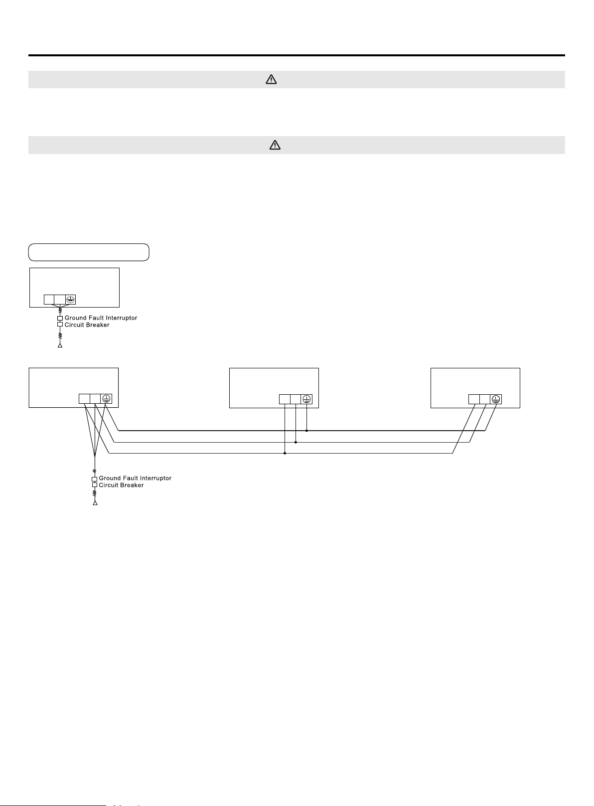
Supply Wiring Drawing
• Indoor units and outdoor units should be connected to separate power breakers.
• Indoor units must share one single electrical breaker. Circuit breaker specications should be calculated. It is
recommended to have both indoor & outdoor units connected to GFCI and surge devices.
power source: 208/230V~, 60Hz
outdoor
L1(L) L2(N)
power source: 208/230V~, 60Hz
Indoor 1
Indoor 2 Indoor 9
L1(L) L2(N)
L1(L) L2(N)
L1(L) L2(N)
......
14
Electrical Wiring
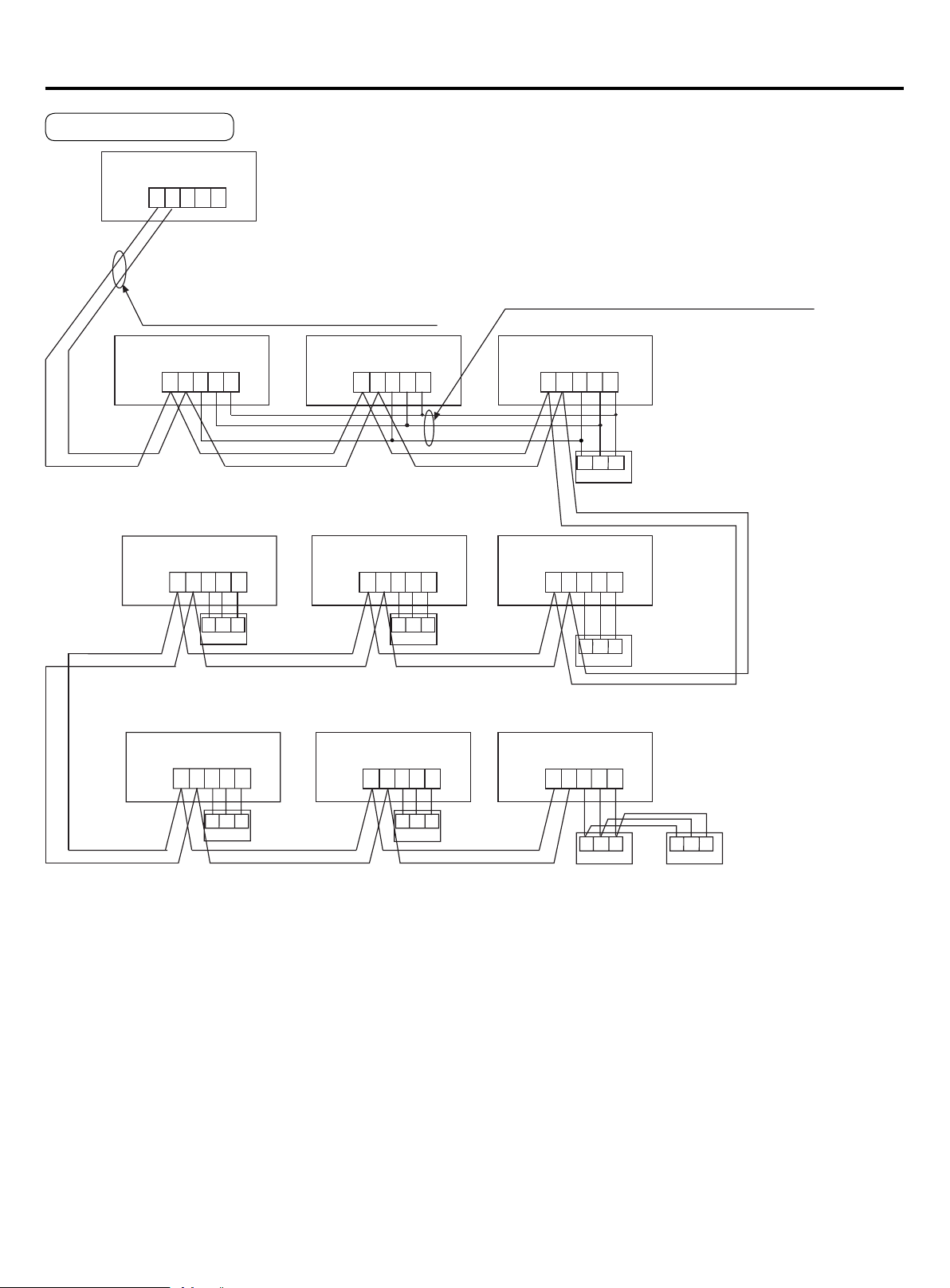
Signal Wiring Drawing
Outdoor units are of parallel connection via three lines with polarity. The main unit, central control and all indoor units
are of parallel connection via two lines without polarity.
There are three ways of connecting the line control and indoor units:
A. One wired control to control multiple units, i.e. 2-9 indoor units, as shown in the above gure, (1-3 indoor units). The
indoor unit 3 is the wire controlled main unit and others are the wired controlled sub units. The remote control and the
main unit (directly connected to the indoor unit of wired control) are connected via three wires with polarity. Other
indoor units and the main unit are connected via three lines with polarity. SW01 on the main unit of wired control is set
to 0 while SW01 on other sub units of wired control are set to 1, 2 and so on in turn. (Please refer to the code setting A
at page 15)
B. One wired control controls one indoor unit, as shown in the above gure (indoor unit 4-8). The indoor units and the
wired control are connected via three lines with polarity.
C. Two wired controls control one indoor unit, as shown in the gure (indoor unit 9). Either of the wired controls can be
set to be the master wired control while the other is set to be the auxiliary wired control. The master wired control and
indoor units, and the master and auxiliary line controls are connected via three lines with polarity.
Note: For DC motor/low ESP duct type, the PCB comes with the terminal blocks. Please be sure to pay attention to do
the wiring according to the labels. The power lines and signal lines go through the metal wire hole separately with the
protective sleeve of the connecting line.
P Q A B C
P Q A B C P Q A B C P Q A B C
A B C
Outdoor
Indoor 1
Indoor 4
Indoor 7
Indoor 2
Indoor 5
Indoor 8
Indoor 3
Indoor 6
Indoor 9
P Q A B C P Q A B C P Q A B C
P Q A B C P Q A B C P Q A B C
A B C A B C
A B C
A B CA B C
A B CA B C
Control wire for wired controller with polarity
Wired controller
Wired controller
Wired controller
Wired controller
Wired controller
Wired controller Wired controller
Wired controller
Communication wire between indoor & outdoor
without polarity
15
Wire gauge size and breaker size for total indoor amp draw. Current NEC guidelines and local codes will trump this chart.
Items
Total
Current of
Indoor Units(A)
Cross
Section
AWG
(mm
2
)
Length
in.(m)
Rated
Current of
Overow
Breaker(A)
Rated current of residual
Circuit Breaker(A)
Ground Fault Interrupter(mA)
Response time(S)
Cross Sectional
Area of Signal Line
<7 14(2.5) 65.6(20) 10 10 A,30 mA,0.1S or below
16 AWG (1.25mm
2
)
≥7 and <11 12(4) 65.6(20) 15 15 A,30 mA,0.1S or below
≥11and <16 10(6) 82(25) 20 20 A,30 mA,0.1S or below
≥16 and <22 8(8) 98.4(30) 30 30 A,30 mA,0.1S or below
≥22 and <27 6(10) 131(40) 30 30 A,30 mA,0.1S or below
• The electrical power line and signal lines must be tightened.
• Every indoor unit must have a ground connection.
• The power wire should be size up if it exceeds the permissible length.
• Shielding of the wire of all the indoor and outdoor units should be connected together and grounded at one point.
• Signal lines should not exceed 3280ft(1000m).
Electrical Wiring
• The shielding lay of the controller wire must be grounded at one end.
• The total length of the controller wire shall not be more than 820ft(250m).
Wired Controller ABC Chart
Length of Controller Wire ft (m) Wiring Dimensions AWG (mm
2
)
≤820(250) 18(0.75) x 3 core shielding line
Indoor Units PCB
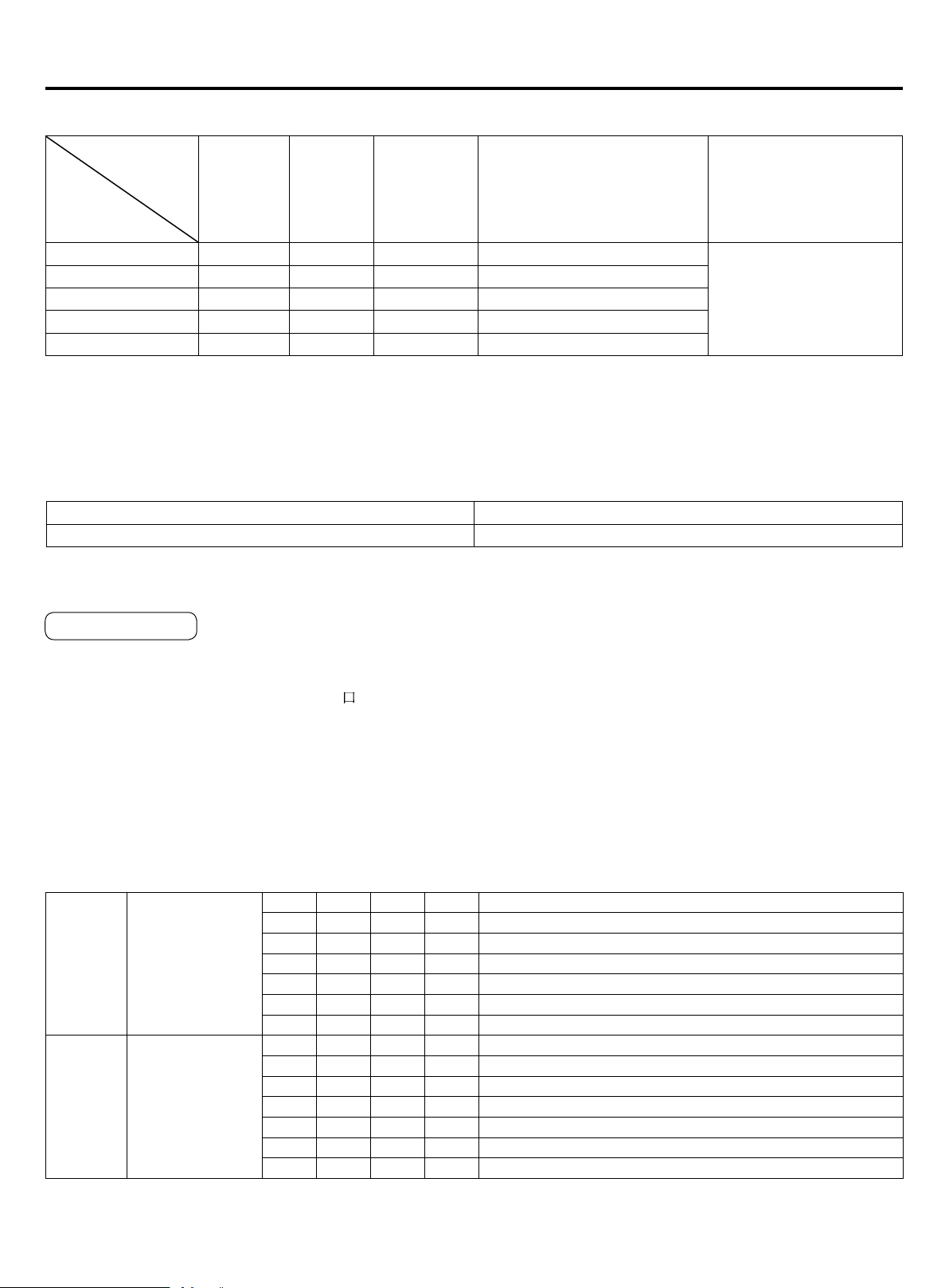
In the following table, 1 represents On and 0 represents Off.
Denition principles of code switches:
SW01 is used to set wire controlled address of and set capabilities of master;SW03 is used to set indoor unit address
(combine original communication address and address of centralized controller)
Note : A wired controller can connected to at most sixteen ultrathin air-duct indoor units.
•The dipswitch is dialed to "On" position with the overline at the state of strapping if the code or overline status is “1” The
dipswitch is dialed to "Off"position with the overline at the state of disconnection if the code or overline status is "0"
• In the table below, the choice in the box "
" refers to the setting of the socket/overline before delivery.
SW01_1
SW01_2
SW01_3
SW01_4
Address of wire
controlled indoor
unit (group
address)
[1] [2] [3] [4] Address of wire controlled indoor unit (group address)
0 0 0 0 0# (wire controlled master unit) (default)
0 0 0 1 1# (wire controlled slave unit)
0 0 1 1 2# (wire controlled slave unit)
0 0 1 1 3# (wire controlled slave unit)
… … … … ……
1 1 1 1 15# (wire controlled slave unit)
SW01_5
SW01_6
SW01_7
SW01_8
Capability of
indoor unit
[5] [6] [7] [8] Capability of indoor unit
0 0 0 1 7000
0 0 1 0 9000
0 0 1 1 12000
0 1 1 0 18000
0 1 1 1 24000
1 0 0 1 30000
(A) Denition and description of SW01
SW01_1-4 is used to set indoor address when grouping multiple indoor units connected to single wired controller YR-
E16B or YR-E17.
SW01_5-8 set capacity of the indoor unit (factory set). Must only set when replacing board.
Dipswitch Setting
16
Electrical Wiring
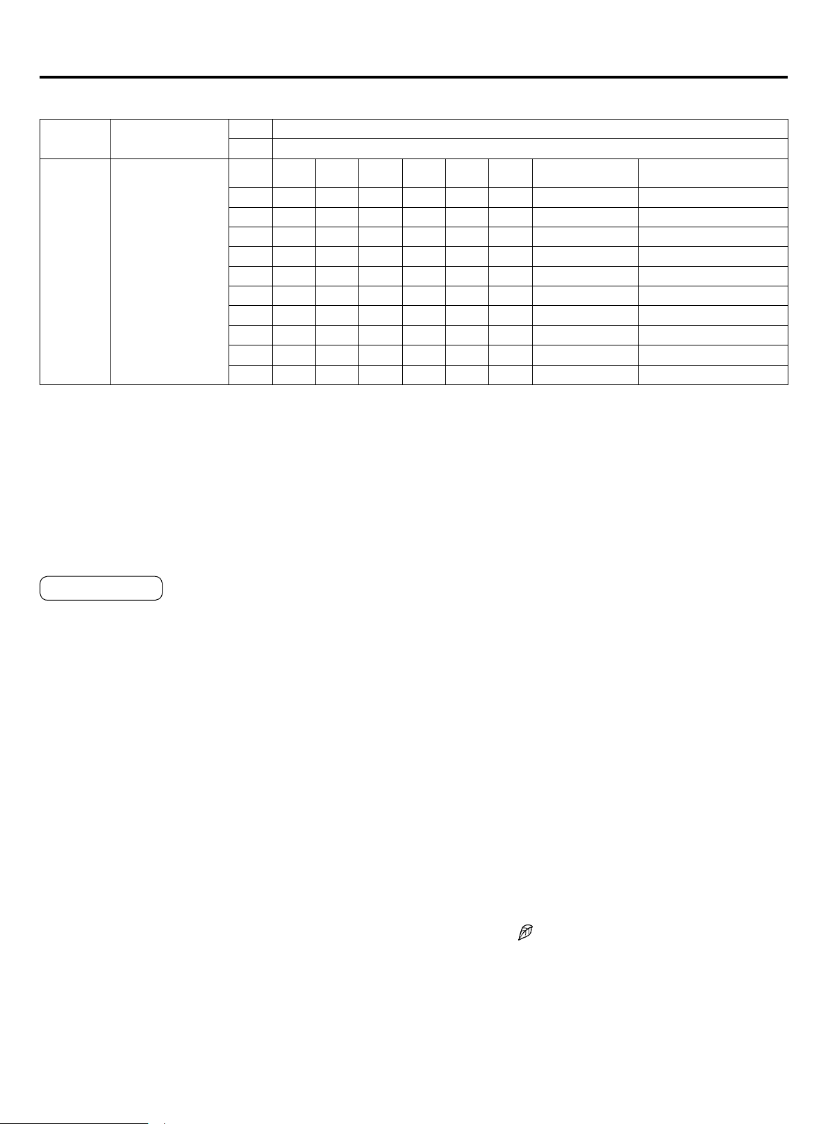
(B) Denition and description of SW03
SW03_1
Address setting
mode
0
Automatic address setting or wired controller address setting (default)
1 Code-set address
SW03_2
~
SW03_8
Code-set indoor
unit address
and centralized
controller address
(Note 2)
2 3 4 5 6 7 8
Address of
indoor unit
Address of centralized
controller
0 0 0 0 0 0 0 0# (Default) 0# (Default)
0 0 0 0 0 0 1 1# 1#
0 0 0 0 0 1 0 2# 2#
… … … … … … … … …
0 1 1 1 1 1 1 63# 63#
1 0 0 0 0 0 0 0# 64#
1 0 0 0 0 0 1 1# 65#
1 0 0 0 0 1 0 2# 66#
… … … … … … … … …
1 1 1 1 1 1 1 63# 127#
Note:
•Set the address by code when connecting the centralized controller or gateway or charge system.
•Address of centralized controller =communication address + 0 or +64.
SW03_ 2=OFF, address of centralized controller =communication address+0=communication address
SW03_ 2=ON, address of centralized controller=communication address+64 (applies when
centralized controller is used and there are more than 64 indoor units)
•To use with 0010451181A in use, it is required to use code for address setting. Set SW03_1=0N
and SW03_ 2=OFF; SW03_3, SW03_ 4, SW03_5, SW03_6, SW03_7 and SW03_ 8 are address codes which are set
according to actual address.
•When connecting central controller, gateway or counting system, set address by dip switch.
Special function
1. Emergency switch:
Press the emergency switch in stop condition, indoor unit
operate with AUTO, AUTO SPEED, 24 Setting modes,
pressure the emergency switch in start condition, indoor
unit will stop operation.
2. Temp. consumption:
The heating mode, the temp. compensation range is
6.8°F(-14°C)~32°F(0°C) .
Set the temp. consumption in Heating mode with remote
controller, heating mode ,set 86°F(30°C) as the reference
point, press the sleep butter 7 times, the buzzer ring 2
times, the unit enter temp. consumption condition. Temp.
consumption data=current temp.-22°F(-30°C)
In the cooling mode, the temp.compensation range is
19.4°F(-7°C)~44.6°F(+7°C).
Set the temp. consumption in Cooling mode with remote
controller, cooling mode ,set 73.4°F(23°C) as the reference
point, press the sleep butter 7 times in 5 seconds, the
buzzer ring 2 times, the unit enter temp. consumption
condition. Temp. consumption data=current temp.-9.4°F(-
23°C).
3. Energy saving setting:
In on condition, press the health button 8 times within 5
seconds, buzzer short ring 4 times that the energy saving
setting is valid, if the buzzer rings 2 times that the energy
saving setting is invalid.
4. Compulsive Defrost:
In heating mode, setting high speed ,set temp. is
86°F(30°C), press sleep button for 6 times, buzzer short
ring 3 times, unit enter manual defrost mode.
5. Auto start function:
In on condition, press the sleep button 10 times within 5
seconds, buzzer short ring 4 times stands for enter auto
restart function; press the sleep button 10 times within 5
seconds, buzzer short ring 2 times stands for exit auto
restart function .
The memory information: on/off condition, mode, fan
speed, setting temp., swing position.
6. Room card Function:
Room card function can realize by remote controller.
Press the light button 12 times with remote controller,if
the buzzer rings 4 times that the room card is valid, if the
buzzer rings 2 times that the room card is invalid.
7. Health anion function:
In on condition, press the "HEALTH" button, when
displaying icon
on LCD display, Air conditioner starts
health anion function operation, press the "HEALTH" button
again n to cancel anion function.
17
• Before switching it on, test the supply terminal tier (L, N terminals) and grounding points with 500V megaohm meter and
check if the resistance is above 1MΩ. It can't be operated if it is below 1MΩ.
• Connect it to the power supply of outdoor units to energize the heating belt of the compressor. To protect the
compressor at startup, power it on 12 hours prior to the operation.
Check if the arrangements of the drainpipe and connection line are correct.
The drainpipe shall be placed at the lower part while the connection line placed at the upper part. Heat preservation
measures should be taken such as winding the drainpipe esp. in the indoor units with heating insulating materials.
The drain pipe should be made a slope type to avoid protruding at the upper part and concaving at the lower part on the
way.
Checkup of Installation
Check if the mains voltage is matching
Check if there is air leakage at the piping joints
Check if the connections of mains power and indoor & outdoor units are correct
Check if the serial numbers of terminals are matching
Check if the installation place meets the requirement
Check if there is too much noise
Check if the connecting line is fastened
Check if the connectors for tubing are heat insulated
Check if the water is drained to the outside
Check if the indoor units are positioned
Test Run & Failure Code
Before Test Run
Do ask the installation personnel to make a test run. Take the testing procedures according to the manual and check if the
temperature regulator works properly.
When the machine fails to start due to the room temperature, the following procedures can be taken to do the compulsive
running. The function is not provided for the type with remote control.
• Set the wired controller to refrigerating/heating mode, press "ON/OFF" button for 5 seconds to enter into the compulsive
refrigerating/heating mode. Repress "ON/OFF" button to quit the compulsive running and stop the operation of the air
conditioner.
Ways of Test Run
Fault Remedies
When any fault appears, refer to “Inquiry of fault records of indoor units" at the previous page, consult the fault code of
line control or the ashing times for LED5 of computer panel of indoor units/health lamp of receiving window of remote
control and nd out the faults as shown in the following table to remove all faults.
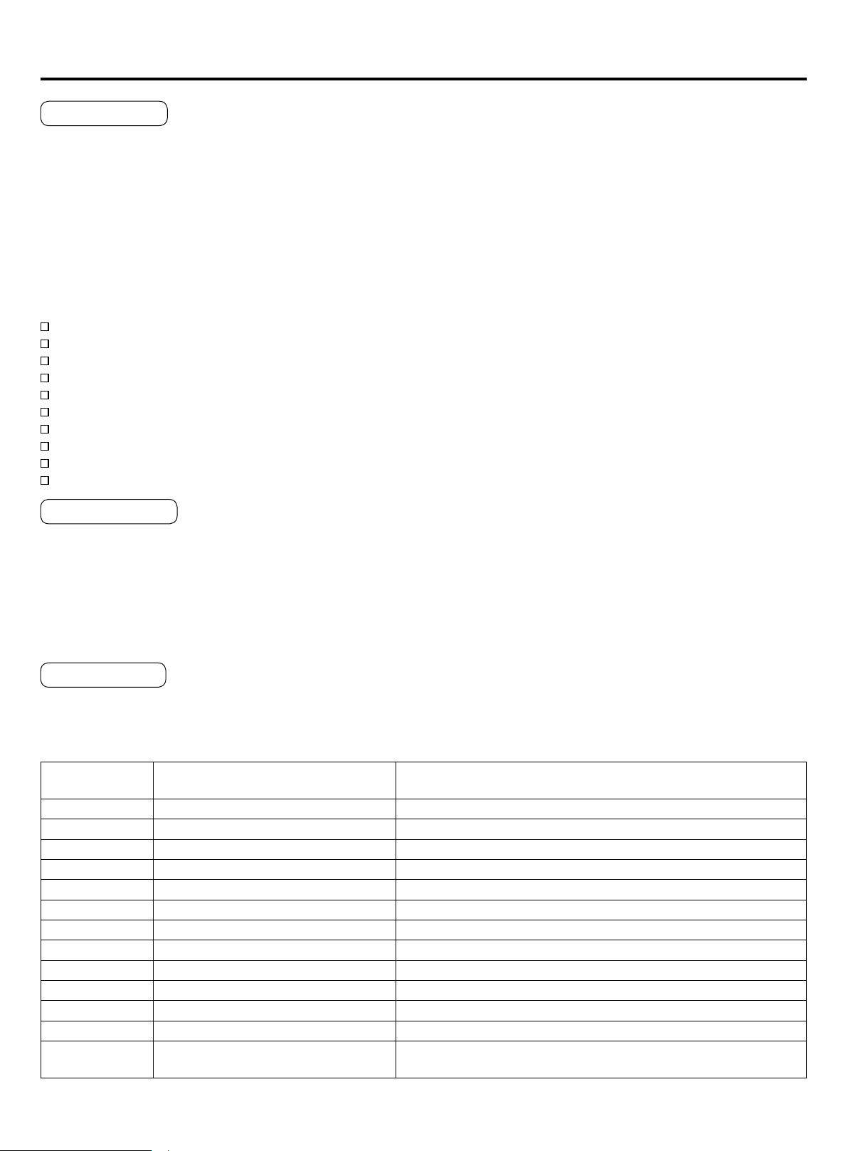
Indoor Unit Faults
Failure code at
wired controller
PCB LED5(Indoor Units) / Receiver
Timer Lamp(Remote Controller)
Fault Descriptions
01 1 Fault of indoor unit ambient temp. transducer TA
02 2 Fault of indoor unit pipe temp. transducer TC1
03 3 Fault of indoor unit pipe temp. transducer TC2
04 4 Fault of indoor unit dual heat source temp. transducer
05 5 Fault of indoor unit EEPROM
06 6 Fault of communication between indoor & outdoor units
07 7 Fault of communication between indoor unit and wired control
08 8 Fault of indoor unit water drainage
09 9 Fault of duplicate indoor unit address
0A 10 Fault of duplicate central control address
0C 12 Fault of zero crossing
0E 14 Fault of DC fan
Outdoor Unit
Code
20 Corresponding faults of outdoor units

Qingdao Haier Air Conditioner Electric Co.,Ltd.
Haier Industrial Park,Qianwangang Road,Eco-Tech Development Zone,Qingdao 266555,
Shandong,P.R.C.