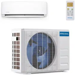

Please read this manual carefully before installation and keep it for future reference.
Please read this manual carefully before installation and keep it for future reference.
V06.09.2020
Owner & Installation
Manual
DIY
®
Multi-Zone

Contents
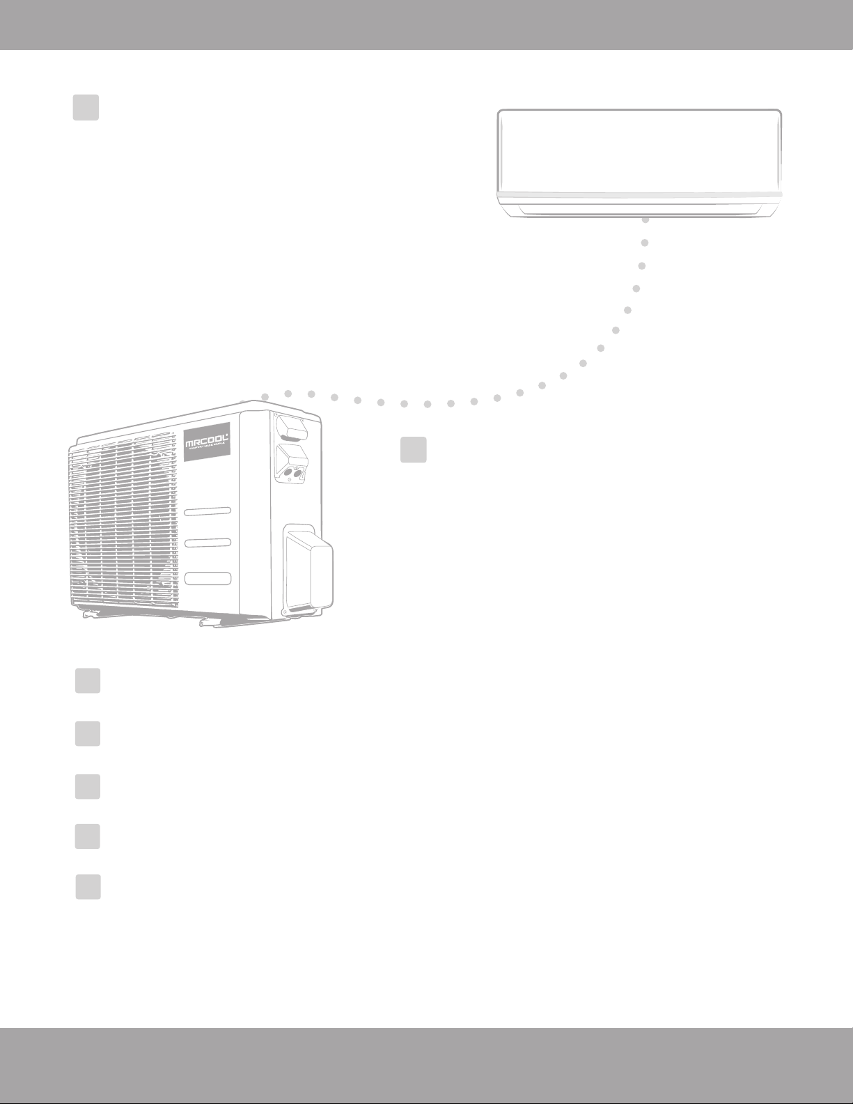
Page 1 mrcool.com
Safety Precautions
Warnings ................................................................................................................................. 3
Cautions .................................................................................................................................. 4
Parts Overview
Parts Diagram ........................................................................................................................ 5
Display Window ..................................................................................................................... 7
Accessories ............................................................................................................................. 8
Operating Instructions
Operating Temperature ......................................................................................................... 10
Manual Operation .................................................................................................................. 10
Airflow Directional Control .................................................................................................... 11
How the A/C & Heat Pump Work .......................................................................................... 12
Special Functions .................................................................................................................... 13
Care and Maintenance
Before Maintenance .............................................................................................................. 14
Cleaning the Unit ................................................................................................................... 14
Cleaning the Air Filter(s) ........................................................................................................ 14
Preparation for Extended Non-Operation .......................................................................... 15
Pre-Season Inspection ........................................................................................................... 15
Installation Diagram...................................................................................................... 16
!
1
2
3
4
DISCLAIMER: You are assuming the risk by handling materials containing refrigerants under pressure that
if not handled properly, refrigerant can cause bodily injury. If you do not feel comfortable conducting this
installation process yourself, we recommend you retain the services of a qualified HVAC professional.
Electrical work must be completed by a qualified electrical technician.
Contents
Indoor Unit Installation ...........17
1. Installation location................................17
2. Attach mounting plate to wall...............18
3. Drill wall hole for connective piping.....18
4. Prepare refrigerant piping ....................20
5. Connect refrigerant piping ....................21
6. Connect drain hose.................................23
7. Wrap piping and cables..........................24
8. Mount indoor unit..................................24
Outdoor Unit Installation ......
25
1. Installation location ............................25
2. Install drain joint .................................26
3. Anchor outdoor unit .......................... 27
6
Refrigerant Piping Connections......................29
Electrical Connections .....................................33
Electrical and Gas Leak Checks.......................36
Test Run.............................................................37
Troubleshooting................................................39
7
8
9
10
11
5
Page 2
mrcool.com
Page 3
Safety Precautions
mrcool.com
Read Before Using
Incorrect usage may cause serious damage or injury.
The seriousness of potential damage or injuries is classified as either a WARNING or CAUTION.
WARNING
CAUTION
WARNING
DO NOT share the electrical circuit with other appliances. Improper or insufficient power supply
can cause fire or electrical shock.
When connecting refrigerant piping,
DO NOT let substances or gases other than the refrigerant
enter the unit. The presence of other gases or substances will lower the unit’s capacity, and may
cause abnormally high pressure in the operation cycle. This may cause explosion and injury.
DO NOT allow children to play with the air conditioner. Children should be supervised around the
unit at all times.
1. Installation must be performed according to installation instructions. Improper installation may
cause water leakage, electrical shock, fire, or may void the warranty.
2. In North America, service or repair must be performed in accordance with the requirement of
NEC and CEC (by authorized personnel or authority having jurisdiction only.) Contact an
authorized service technician for repair or maintenance of the unit.
3. Only use the included accessories and specified parts for installation. Using non-standard parts
can cause water leakage, electrical shock, or fire and may cause the unit to fail.
4. Install the unit in a firm location that can support the unit’s weight. If the installation location
cannot support the weight, or the installation is performed improperly, the unit may fall and
cause serious injury and/or damage.
5. For all electrical work, follow all appropriate wiring standards, regulations, and the Installation
Manual.
6. You must use an independent circuit to supply power. Do not connect other appliances to the
same circuit. Insufficient electrical capacity or defects in electrical work can cause electrical
shock or fire.
This symbol indicates ignoring instructions may cause death or serious injury.
This symbol indicates that ignoring instructions may cause moderate injury
to your person, damage to your unit, or other property.
This symbol indicates that you should NEVER perform the indicated action.
!
Safety Precautions
DISCLAIMER: You are assuming the risk by handling materials containing refrigerants under pressure that if not
handled properly, refrigerant can cause bodily injury. If you do not feel comfortable conducting this installation
process yourself, we recommend you retain the services of a qualified HVAC professional.
Electrical work must be completed by a qualified electrical technician.
Page 4
Safety Precautions
mrcool.com
Note about Flourinated Gasses:
7. For all electrical work, fuse the specified cables. Connect cables tightly, and clamp them securely to prevent external
forces from damaging the terminal. Improper electrical connections may overheat, causing fire and/or electrical
shock.
8. If connecting power to fixed wiring, the following is required: 1. An all-pole disconnection device (which
has at least 3mm clearances in all poles and has a leakage current that may exceed 10mA), 2. A residual
current device (which has a rated residual operating current not exceeding 30mA) and 3. A disconnection
box, must be incorporated in the fixed wiring that is in accordance with the wiring rules as shown in the
Electrical Connections section of this manual.
9. In certain functional environments, such as kitchens, server rooms, etc., the use of specially designed
air-conditioning units is highly recommended. If the supply cord is damaged, it must be replaced by
the manufacturer, its service agent or similarly qualified persons in order to avoid a hazard.
10. This appliance is not intended for use by persons (including children) with reduced physical, sensory
or mental capabilities, or lack of experience and knowledge unless they have been given supervision
or instruction concerning use of the appliance by a person responsible for their safety. Children
should be supervised to ensure that they do not play with the appliance.
DO NOT install the unit in a location that may be exposed to combustible gases. If combustible gas
accumulates around the unit, it may cause fire.
DO NOT operate your air conditioner in a wet room such as a bathroom or laundry room. Too
much exposure to water may cause electrical components to short circuit.
DO NOT operate the air conditioner with wet hands. This may cause electrical shock.
DO NOT climb onto or place objects on top of the outdoor unit.
1. The product must be properly grounded during installation, or electrical shock may occur.
2. Install drainage piping according to the instructions in this manual. Improper drainage may cause
water damage to your home and property.
1. This air-conditioning unit contains flourinated gases.
2. For specific information on the type of gas and the amount, please refer to the relevant label on
the unit itself.
3. Service, maintenance, and repair of this unit must be performed by a certified technician.
4. Product uninstallation and recycling must be performed by a certified technician.
5. If the system has a leak-detection system installed, it should be checked for leaks at least every
12 months.
6. Keep a record of all leak checks for the lifetime of the unit.
Page 5
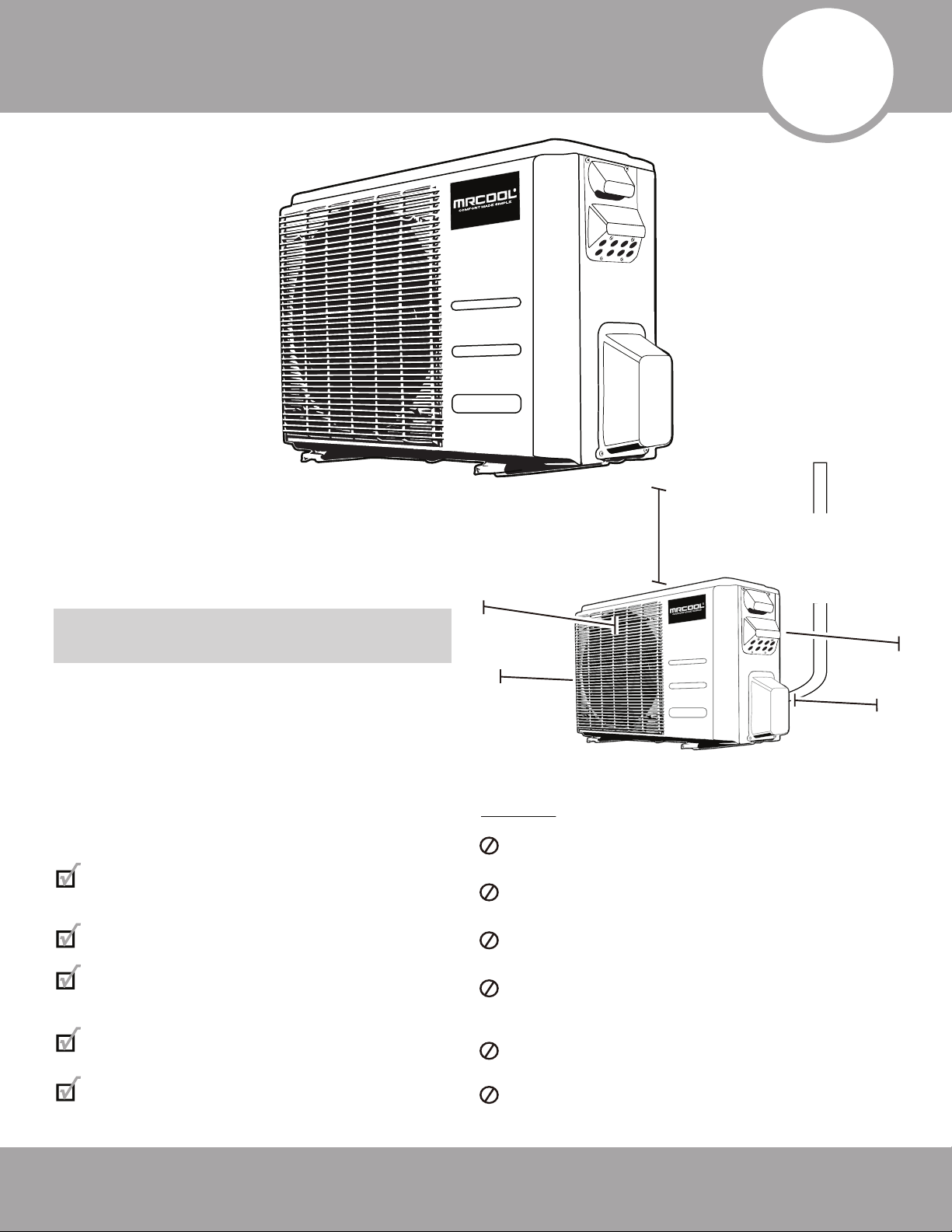
Safety Precautions
mrcool.com
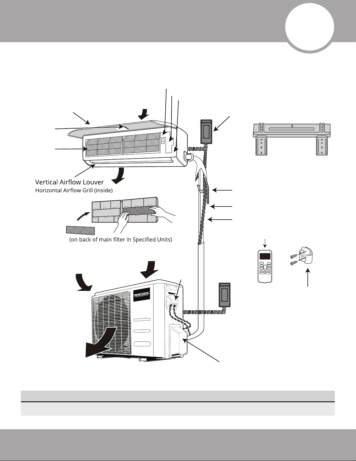
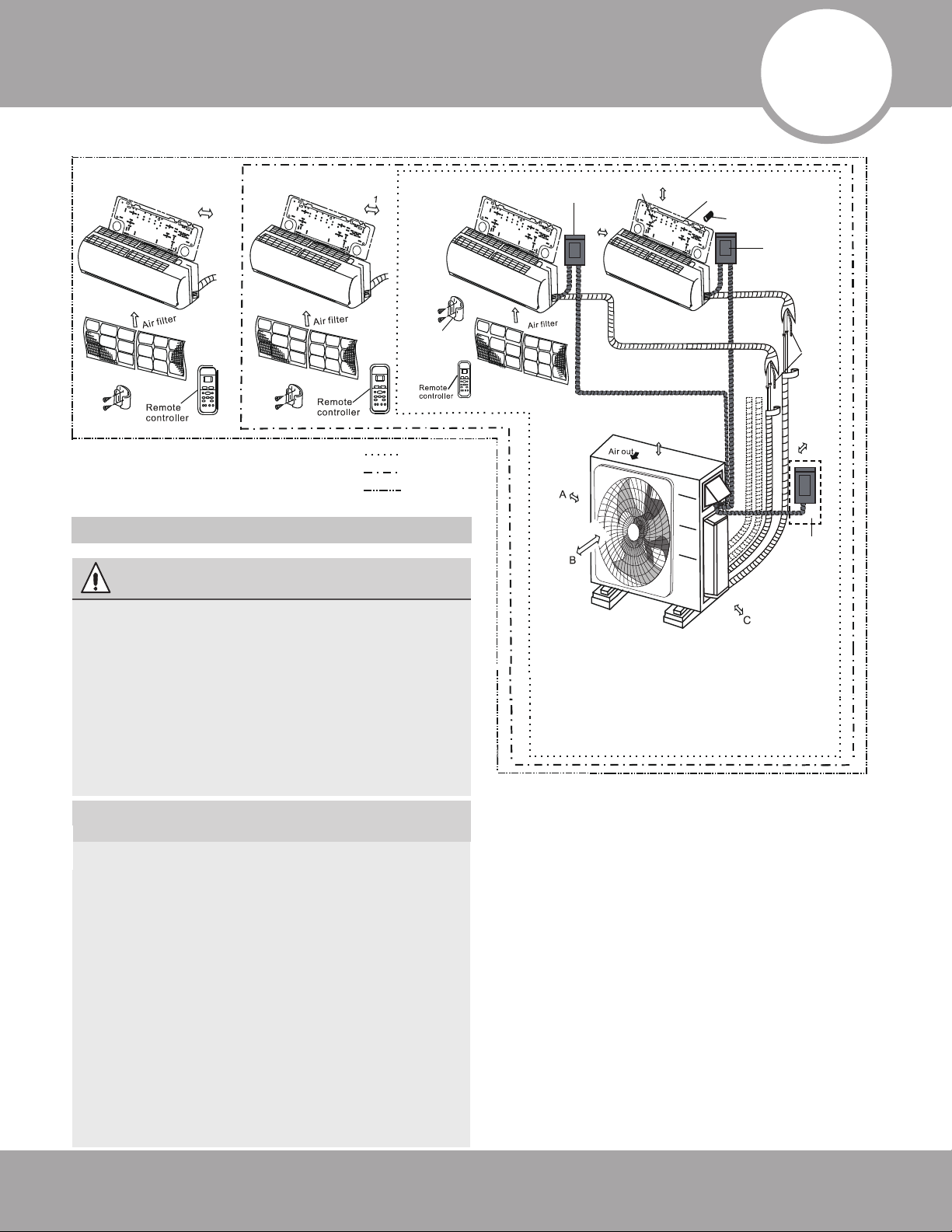
Fig. 1.1
Remote Control
Remote Holder
Refrigerant Piping
Signal Cable(inside conduit)
Electrical
Access
Drainage Pipe
Front Panel
(with display)
Wall Mounting Plate
Outdoor Unit
Power Cable
(inside conduit)
Fresh Air Filter
Air inlet (rear)
Air inlet (side)
Air outlet
Air outlet (bottom)
Indoor Unit
(Interior / Air Handler)
Outdoor Unit
(Exterior / Condenser)
Refrigerant Pipe Connection
and Stop Valve (under cover)
Signal Cable
(inside conduit)
Air inlet (rear)
Smart Controller
Module USB Port
Indoor temperature sensor
Electrical Access
Air Filter
Forced cooling button
Air-break switch
NOTE: The installation must be performed in accordance with the requirement of local and
national standards. Both power cable and signal cable should be protected by the conduit.
1
Parts Overview
NOTE ON ILLUSTRATIONS
Illustrations in this manual are for explanatory purposes. The actual shape of your unit may vary.
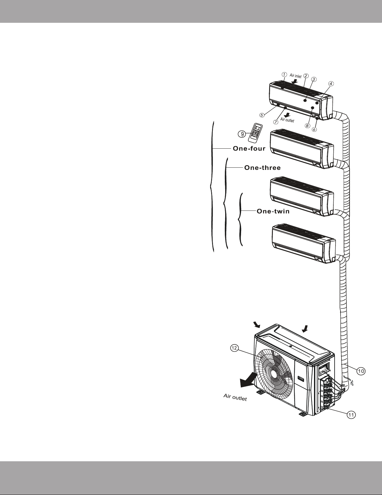
Indoor unit
1. Panel frame
2. Rear air intake grill
3. Front panel
4. Air purifying filter & Air filter (behind)
5. Horizontal louver
6. LCD display window
7. Vertical louver
8. Manual control button (behind)
9. Remote controller holder
Outdoor unit
10. Drain hose, refrigerant connecting pipe
11. Stop valve
12. Fan hood
Page 6
Overview - Diagram
mrcool.com
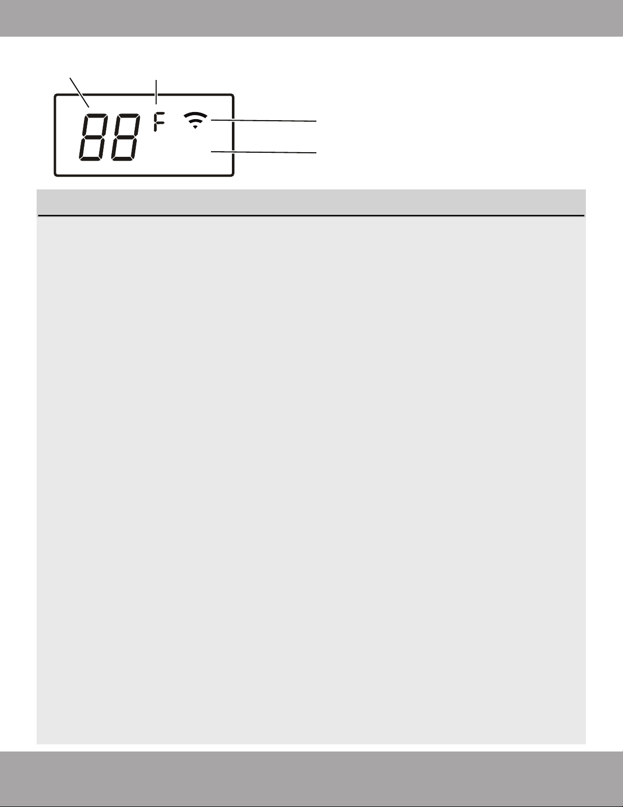
Page 7
Overview - Display
mrcool.com
1. Digital Display:
Displays the Temperature Setting when the air conditioner is operational.
Displays the Room Temperature when in FAN mode.
Displays the self-diagnostic codes.
Displays “ON” for three seconds when the Timer is ON and/or Fresh, Swing, Turbo or Silence
feature is activated.
Displays “OF” for three seconds when the Timer is switched OFF.
Displays “OF” for three seconds when the Fresh, Swing, Turbo or Silence feature is canceled.
Displays “dF” when Defrosting operation is active.
Displays “cF” when Anti-Cold Air feature is active in HEAT mode (when air temp is low).
Displays “SC” during Self Clean operation (if feature is available).
Displays “FP” when Freeze Protection is active, operating under 46.4 °F (8 °C) (if feature is
available).
2. Units of Measurement:
Displays “°C” for Celsius or “°F” for Fahrenheit. Default units are “°F” (Fahrenheit) and can be
switched by simultaneously pressing and holding both the up and down buttons on the remote
control.
According to the operation mode (heat / cool, etc.), the Units of Measurement will display in
different colors;
· Under Cool or Dry mode, it always displays as cool colors.
· Under Heat mode, it always displays as a warm color.
3. Wireless Mode:
Displays when the wireless control feature is activated.
NOTE: A guide for using the infrared remote - “Remote Manual” - is included in this literature
package.
°
ECO
1
3
4
2
Fig. 1.2
Display (on front panel of indoor unit) see fig. 1.2
Page 8
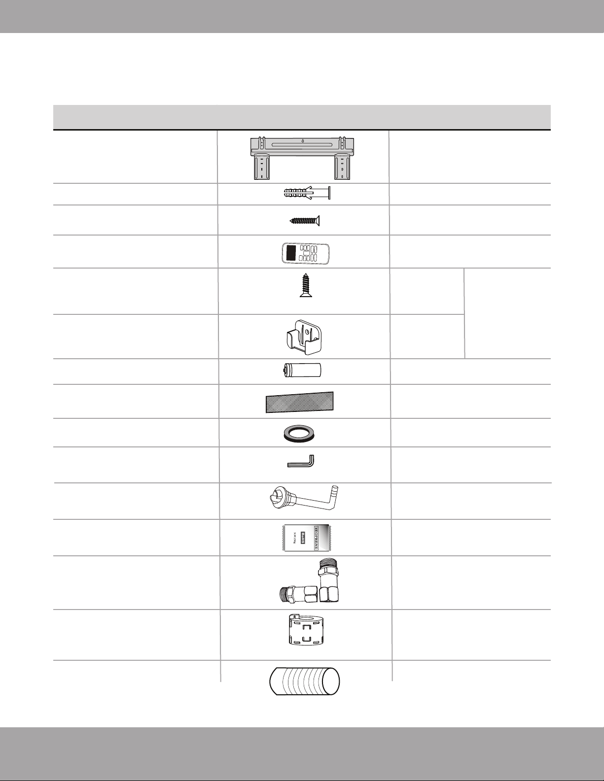
Overview - Accessories
mrcool.com
1liquid side adapter and 1
suction side adapter used for
installing indoor units rated
24K BTU or greater.
1(Attach to connective cable
between indoor and outdoor
unit to reduce static)
1 (Sealant for Wall Sleeve)
1 (Only for use when elevated)
1
1
1
1
1
1
Neoprene
Line-Set Adapter Set
(Included with 4-zone
only)
Magnetic Ring
Plastic Wall Sleeve
Anchor
Mounting plate
fixing screw
Remote control
Fixing screw for remote
controller holder
ST2.9 x 10
Remote control holder
Dry battery AAA.LR03
Air freshening filter
Seal
Allen wrench
Drain joint
Mounting plate
5
5
2
1
Optional
Parts
2
PART LOOKS LIKE... QUANTITY
The air conditioning system includes the following accessories. Use all of the
installation parts and accessories to install the air conditioner. Improper installation may
result in water leakage, electrical shock, fire, or equipment failure.
Note: Illustrations are for explanatory purposes only - The actual shape may vary.
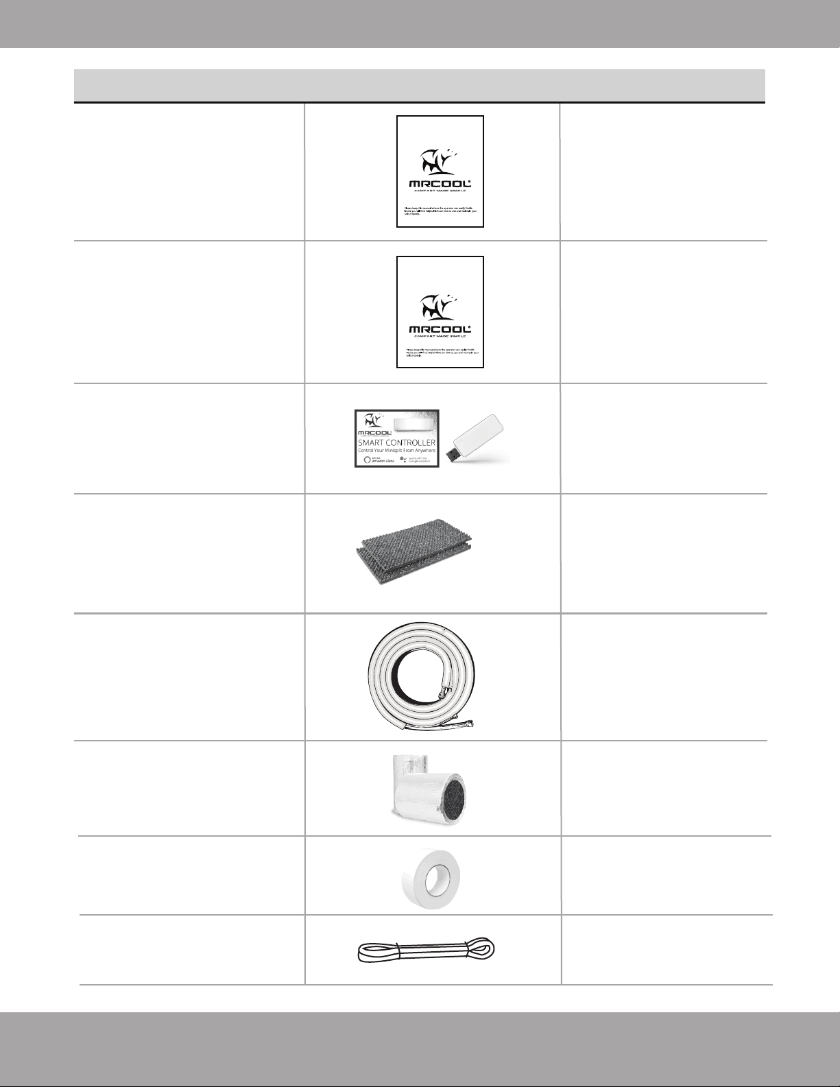
Page 9 mrcool.com
1
1
Depends on Purchase
2
4
16 ft (5m)
(Apply to the quick
connectors of the pipe)
1
Overview - Accessories
2
(w/ Manual in
Controller Box)
Owner & Installation
Manual
Remote Control
Manual
Smart Controller Kit
Sound deadening
pads
Quick Connect®
line set (refrigerant
pipe)
Line set sizes include:
16ft, 25ft
Insulation material
Tape
Drain Pipe
PART LOOKS LIKE... QUANTITY
Please read this manual carefully before installation and keep it for future reference.
Owner’s Manual
DIY
®
Multi-Zone
For more details visit www.MrCool.com
For more details visit www.MrCool.com
Please read this manual carefully before installation and keep it for future reference.
Remote Control
User Manual
Page 10
Safety Precautions
mrcool.com
CAUTION
Manual Operation
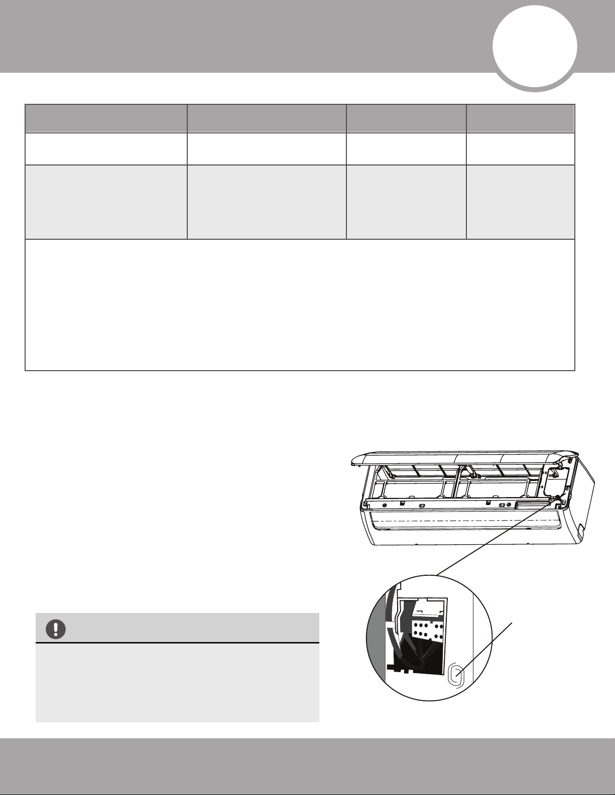
Units are equipped with a switch to run emergency operation mode. It can be accessed by opening the
front panel. This switch is used for manual operation in case the remote fails to work or maintenance
is necessary.
Manual
Control
Button
(Forced cooling)
NOTE:
The unit must be turned off before operating the manual
control button. If the unit is operational, continue pressing the
manual control button until the unit is off.
1.
Open and lift the front panel up to an angle until it remains
fixed with a clicking sound.
2.
One press of the manual control switch will lead to the forced
AUTO operation. If the switch is pressed twice within five
seconds, the unit will operate under forced COOL operation.
3.
Close the panel firmly to its original position.
• This switch is used for testing purposes only.
Please do not use it unless necessary.
•To restore the remote control operation,
use the remote control directly.
Fig 2 .1
2
Operating Instructions
Room Temperature
Cooling Operation Heating Operation Drying Operation
63°F~90°F
(17°C~32°C)
32°F~86°F
(0°C~30°C)
50°F~90°F
(10°C~32°C)
-13°F~122°F / -25°C~50°C
-13°F~86°F
(-25°C~30°C)
32°F~122°F
(0°C~50°C)
Outdoor
Temperature
NOTE:
1. Optimum performance will be achieved within these operating temperatures. If the unit is used outside
of the above conditions, certain safety protection features might come into operation and cause the unit
to function abnormally.
2. If the air conditioner runs for a long time in cooling mode and the humidity is high (over 80%),
condensed water may drip out of the unit. In this case, set the vertical air flow louver to its maximum
angle (vertical toward the floor), and set it to HIGH fan mode.
Page 11
Operating Instructions
mrcool.com
Range
fig 2.4
fig 2.3
Deflector Rod
Horizontal Louver
(Horizontal Airflow
Grill inside)
Range
fig 2.2
Vertical
Louver
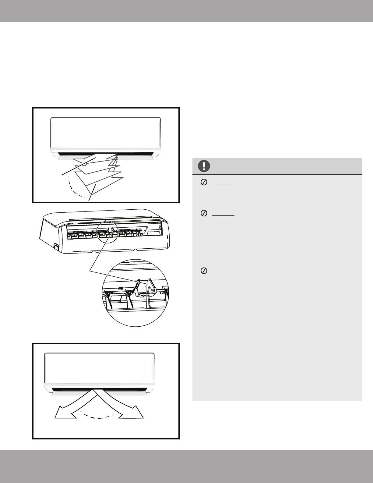
CAUTION
DO NOT put your fingers into the panel of the
blower and suction side. The high speed fan
inside may cause injury.
DO NOT operate the unit for long periods of time
with the airflow direction set downward in
cooling or dehumidifying mode. Otherwise,
condensation might occur on the surface of the
vertical louver causing moisture to drop on to
the floor or furnishings.
DO NOT move the vertical louver manually.
Otherwise, the vertical louver will be out of sync.
If this happens, cease operation. Turn off the
power to the unit, remove the wireless module
from the front cover, turn off the power to the
circuit (at the breaker), wait a few seconds, and
turn the power back on at the breaker. Reinstall
the wireless module and power the unit back on.
After a quick restart, the vertical louver may
remain static for approximately 10 seconds.
The open angle of the vertical louver should not
be set too small, as it will restrict airflow and
reduce COOLING and HEATING performance.
1.
2.
Adjust Vertical (Up / Down) Air Flow using Vertical
Louver (fig2.2):
Perform this function while the unit is in operation. Use
the remote control to adjust the Vertical Louver /
Vertical Air Flow direction. The vertical louver can move
in small increments for each press, or continuously
swing up and down automatically. Please refer to the
“REMOTE CONTROL USER MANUAL” for details.
Adjust Horizontal (Left/ Right) Airflow using
Horizontal Louver (fig 2.3, fig 2.4):
Move the Deflector Rod manually to adjust the air flow
side to side (left / right) as desired.
Airflow Directional Control
·
Adjust the airflow direction properly.
Otherwise, it may cause discomfort or
uneven room temperatures.
· Adjust the vertical louver using the remote.
· Adjust the horizontal louver manually.
Page 12
Operating Instructions
mrcool.com
Basic Operation Modes:
AUTO / COOL / DRY / HEAT (Model dependent).
Auto Operation:
When you set the air conditioner in AUTO mode, it will
automatically select cooling, heating or fan-only operation
depending on set temperature and room temperature.
The unit will control the room temperature automatically,
according to the temperature point you set.
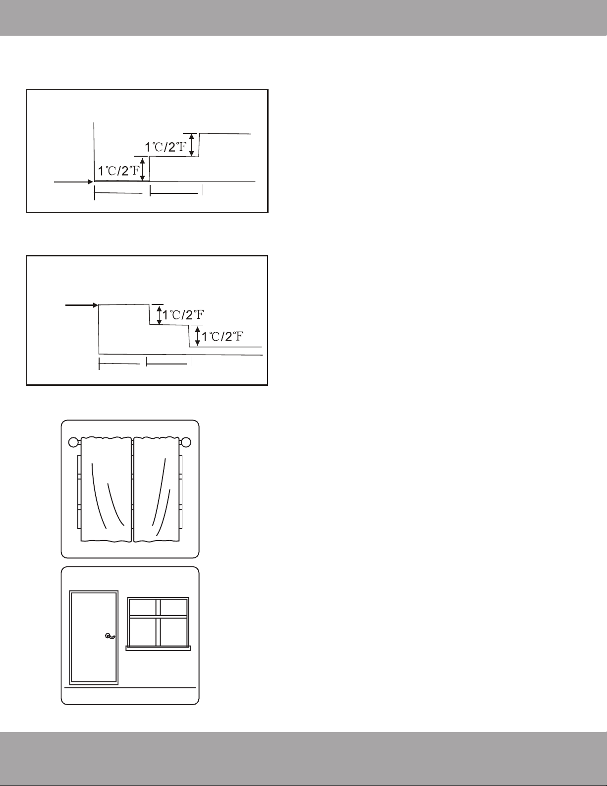
SLEEP Operation:
When selected, the temperature will increase while cooling
or decrease while heating by 1°C / 2°F per hour for the first
2 hours. Thereafter it keeps this new temperature for 6
hours before SLEEP mode switches off.
DRYING Operation:
The temperature is regulated while dehumidifying by
intermittently switching the cooling or fan-only operation on
and off. The fan speed is set to LOW.
HEATING Operation:
This unit is a heat pump by design. By reversing the air
conditioning process, it absorbs heat from outdoors and
transfers it to the indoor unit. As a result, the operating
performance and efficiency is reduced as the outdoor air
temperature drops. If you feel that the heating
performance is insufficient, it is recommended that you
supplement heating with other appliances.
Optimal Operation:
To achieve optimal performance, please note the following:
· Adjust the airflow direction correctly, so that it is not
towards people or at an extreme angle.
· Adjust the temperature to achieve moderate comfort
levels. An excessively low or high temperature setting
wastes energy.
· Keep windows and doors closed to improve
performance.
· Limit energy usage (run time) by using the TIMER
function.
· Do not put any objects near the air inlets / outlets. Doing
so would impair performance and possibly shut down
the unit.
· Inspect the air filters periodically and clean them as
needed.
1 hour
1 hour
Set
Temperature
Cooling
SLEEP operation
8 hours
timer OFF
Set
Temperature
Heating
1 hour
1 hour
SLEEP operation
8 hours
timer OFF
How the air conditioner works
Closing the
curtains while
heating also
helps keep the
heat in
Doors and
windows should
be kept closed

Page 13
Operating Instructions
mrcool.com
Special Functions
Refrigerant Leakage Detection (optional):
When refrigerant leakage is detected, the indoor unit will display “EC” or “ELOC” code or flash LEDs,
depending on the model.
Louver Angle Memory Function (optional):
Within the scope of the safe operation angle, the horizontal louver angle is memorized and returns to
the position last selected by the user. If it exceeds the safe operation angle, it will default within the
safe operation range. However, it will not return to safe operation angle when Turbo mode is set or
the unit is in manual control or after a power interruption. Subsequently, it is strongly recommended
that the horizontal louver angle not be set too small, to avoid possible condensation leakage.
Anti-Mildew Function (optional):
When the unit is turned off, in COOL, DRY, AUTO (cool) modes, it will continue to run for about 10
minutes with a low fan airflow. This aids in drying up any condensation inside the unit to prevent
mildew growth. Do not restart the air conditioner until the unit is completely off.
Optimal Operation:
In the event of a power interruption such as a blackout, the air conditioner will stop. It will then
restart automatically and resume the previous operation when the power supply returns.
Wireless Smart Control Function:
Connect the wireless control module via the USB port in the back of the front cover of the indoor unit
for the unit to be controlled by remote control and/or smartphone app.
Clean Air Filter Reminder (optional):
After 240 hours of operation, the indoor display window will display and flash “CL” as a reminder to
CLEAN the air filter for more efficient operation. After 15 seconds, the system will revert back to the
previous display again. When the “CL” indicator appears and flashes, please press the LED button on
the remote control 4 times or press the manual control button 3 times to reset the hours. If you don’t
reset the reminder, the “CL” indicator will flash again when you restart the unit.
Replace Air Filter Reminder (optional):
After 2880 hours of operation, the indoor display window will display and flash “nF” as a reminder to
REPLACE the air filter for more efficient operation. After 15 seconds, the system will revert back to
the previous display again. When the “CL” indicator appears and flashes, please press the LED button
on the remote control 4 times or press the manual control button 3 times to reset the hours. If you
don’t reset the reminder, the “nF” indicator will flash again when you restart the unit.
Mute Function (optional):
Press the LED button on the remote to turn off the LED display and silence the buzzer of the indoor
unit to create a quiet and comfortable environment.
Operation Mode Selection
While two or more indoor units are simultaneously operating, make sure the modes do not conflict with
each other. The heat mode claims precedence over all other modes. If the unit intially started to operate
in HEAT mode, the other units can operate in HEAT mode only. For example: If the unit intially started
operating under COOL (or FAN) mode, the other units can operate under any mode except HEAT. If one
of the unit selects HEAT mode, the other operating units will stop operation and display ”--” (for units with
display window only) or the auto and operation indication light will flash rapidly, the defrost indication light
will turn off, and the timer indication light will remain on (for units without a display window).
Page 14
Operating Instructions
mrcool.com
FilterTab
CAUTION
Power supply must be disconnected before attempting
to clean or service. Failure to do so can cause electrical
shock.
DO NOT use benzene, thinner, polishing powder, or
similar solvents for cleaning. These may cause the
plastic to crack and/or deform.
DO NOT clean the unit with excessive amounts of water.
DO NOT touch the metal parts of the unit when
removing the filter. Injuries can occur when
handling the sharp metal edges.
DO NOT use water to clean inside the air
conditioner. Exposure to water can destroy the
insulation and possibly lead to electric shock.
DO NOT use a chemically treated cloth or duster to
clean the unit.
DO NOT touch air freshening (Plasma) filter for at least
10 minutes after turning off the unit.
DO NOT clean the unit with combustible cleaning
agents. These could cause fire or defomation.
DO NOT wash air filter with water hotter than 40°C /
104°F.
DO NOT expose the filter directly to the sun, it may
shrink. Dry it in the shade.
Before performing maintenance, power off the unit.
Then, disconnect the power circuit at the breaker.
Cleaning the Unit:
Wipe the unit with a soft dry cloth. If the unit is very dirty, wipe it
with a cloth soaked in warm water. DO NOT use bleach or abrasives.
Cleaning the Air Filter and Air Freshener:
A clogged air filter can greatly reduce the heating and cooling
efficiency of this unit. It is recommended to clean the unit every 2
weeks. It is recommended to clean the filter every 30 days or
bi-weekly if you have indoor pets.
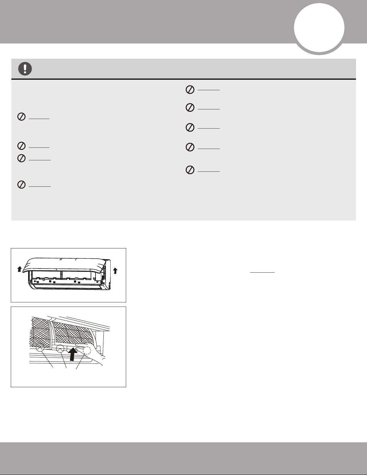
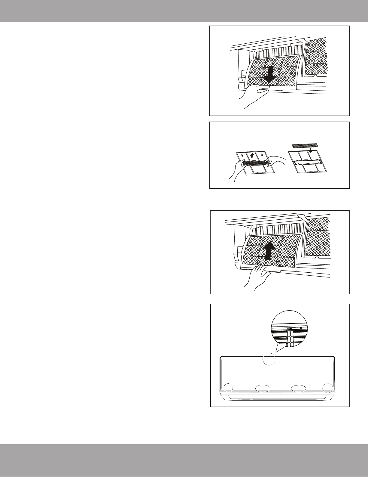
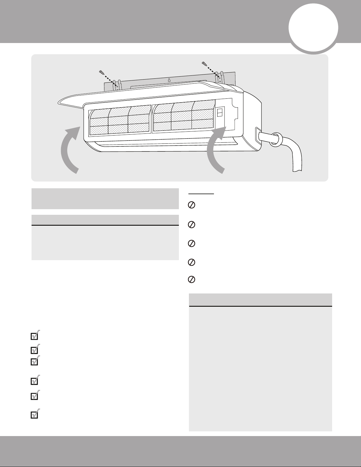
1. Open the front panel by carefully lifting both ends at the same
time. At a certain angle, there will be an audible click and the lid
becomes self-supporting. For some models, suspension bars are
provided and required to prop up the lid.
2. Use the filter tabs to lift the filter slightly upward and then toward
you.
1
2
3
Care and Maintenance
Page 15
Care and Maintenance
mrcool.com
Panel buckles
3. Then, extract the filter by gently drawing it
downward. Replace as necessary.
4. Unclip the small air freshening filter from the larger
air filter. Replace as necessary. Otherwise, clean it
with a vacuum and clip it back into place after
cleaning the larger air filter as outlined in Step 5.
5. Clean the large air filter with warm, soapy water. Be
sure to use a mild detergent. Rinse with fresh water.
Shake off excess water and dry in a cool area.
6. Re-clip air freshening filter into large air filter.
7. Re-fit air filter back into the unit by reversing Steps 2
and 3 - gently pushing the top up into the unit and
then lowering the bottom into place.
8. Close the front panel. Make sure the buckles fully fit
and the panel is completely closed.
Preparation for Extended non-Operation:
If you plan not to run the unit for a long period of time
(e.g. from the end of summer to the beginning of the
following summer), perform the following:
1. Clean the indoor unit and filters as previously
outlined.
2. Operate the unit in FAN only mode for at least 8
hours to dry out the inside of the unit.
3. Turn off the unit. Turn off the power circuit at the
breaker. The unit should be the only appliance on
the circuit.
4. Remove the batteries from the remote control.
5. The outdoor unit requires periodic maintenance as
well. However, do not attempt this on your own. It
is highly recommended that you contact a qualified
service professional.
Pre-Season Inspection:
After prolonged non-operation, perform the following:
1. Check for Damaged or Disconnected Wires.
2. Clean the Indoor Unit and Filters
3. Check for Water and Oil Leaks
4. Check for Blockages in Airflow Inlet and Outlet
5. Replace Batteries
Air Freshening Filter
4
3
Page 16mrcool.com
Installation Summary - Indoor Unit
•
•
CAUTION
•
To prevent wall damage, use a stud finder to
locate studs.
A minimum pipe run of 9.8 ft (3 m) is required
to minimise vibration & excessive noise.
Two of the A, B, and C air circulation pathways
must be free from obstructions at all times.
This illustration is for demonstration
purposes only.
The actual shape of your air condtioner may
vary from the illustration.
•
•
Safety Precautions
1
2
3
4
1
Installation plate
Mounting screw
ST3.9
×25-C-H
Clip anchor
(1)
Remote
controller
holder
4 3
2
Air-break Switch
Drainage
Pipe
Air-break
Switch
Outdoor Unit
Power Cable
4
Installation Diagram
NOTE:
27K BTU 3 Zone DIY Multi-Zone Condenser
The combined linear length of all line-sets shall not
exceed 197 ft. The linear length of any single line-set
shall not exceed 75 ft. The laterial length between the
outdoor unit and any indoor unit shall not exceed 49 ft.
The laterial length between the lowest indoor unit and
the highest indoor unit shall not exceed 33 ft.
36K BTU 4 Zone DIY Multi-Zone Condenser
The combined linear length of all line-sets shall not
exceed 262 ft. The linear length of any single line-set
shall not exceed 75 ft. The lateral length between the
outdoor unit and any indoor unit shall not exceed 49 ft.
The lateral length between the lowest indoor unit and
the highest indoor unit shall not exceed 33 ft.
One-Two
One-Three
One-Four
More than
24in (60cm)
More than
24in (60cm)
More than
12 in (30cm)
More than
79in (200cm)
More than
12 in (30cm)
More than
4.7 in (12 cm)
More than 6 in
(15 cm)
More than
4.7 in (12 cm)
More than
4.7 in (12 cm)
Page 17 mrcool.com
Installation Summary - Indoor Unit
Installation Instructions
– Indoor Unit
PRIOR TO INSTALLATION:
Before starting installation, verify the
product series labels on the product boxes
match the indoor unit and outdoor unit. All
products must belong to the same series.
Step 1: Select installation location
Before installing the indoor unit, you must
choose an appropriate location. The following
standards will help you choose an appropriate
location for the unit.
Proper installation locations meet the
following standards:
Good air circulation
Convenient drainage
Noise from the unit will not disturb
other people
Firm and solid—the location will not vibrate
Strong enough to support the weight of
the unit
A location at least 3 ft (1m) from all other
electrical devices (e.g., TV, radio, computer)
DO NOT install unit in the following locations:
Near any source of heat, steam, or
combustible gas
Near flammable items such as curtains
or clothing
Near any obstacle that might block air
circulation
Near a doorway or where outside air may blow
directly on indoor unit
In a location subject to direct sunlight
NOTE ABOUT WALL HOLE:
If there is no fixed refrigerant piping:
While choosing a location, be aware that
you should leave ample room for a wall
hole (see Drill wall hole for connective
piping step) for the signal cable and
refrigerant piping that connect the indoor
and outdoor units. The recommended
position for all piping is the right side of
the indoor unit (while facing the unit).
After piping and signal wiring are
installed, use provided neoprene to pack
the space making it airtight.
5
Indoor Unit Installation
Page 18mrcool.com
Indoor Unit Installation
Refer to the following diagram to ensure proper distance from walls and ceiling:
Step 2: Attach mounting plate to wall
The mounting plate is the device on which you will
mount the indoor unit.
1. Remove the screw that attaches the mounting
plate to the back of the indoor unit.
2. Place the mounting plate against the wall in a
location that meets the standards in the
Select Installation Location step. See
Mounting Plate Dimensions for detailed
information on mounting plate sizes.
3. Drill holes for mounting screws in places that:
• have studs and can support the weight of
the unit
• correspond to screw holes in the mounting
plate
4. Secure the mounting plate to the wall with the
screws provided.
5. Make sure that the mounting plate is flat against
the wall.
NOTE FOR CONCRETE OR BRICK WALLS:
If the wall is made of brick, concrete, or similar
material, drill 0.2in-diameter (5mm-diameter)
holes in the wall and insert the sleeve anchors
provided. Secure the mounting plate to the
wall by tightening the screws directly into the
clip anchors.
Step 3: Drill wall hole for connective piping
You must drill a hole in the wall for refrigerant piping,
the drainage pipe, and the signal cable that will
connect the indoor and outdoor units.
1. Determine the location of the wall hole based on
the position of the mounting plate. Refer to
Mounting Plate Dimensions on the next page
to help you determine the optimal position. Refer
to Fig. 5.3 wall hole diameter and install at a slight
angle to facilitate drainage.
2. Using a core drill [3.54in (76.2mm)], drill a hole in the
wall. Make sure that the hole is drilled at a slight
downward angle, so that the outdoor end of the
hole is lower than the indoor end by about 0.2 to
0.275in (5mm-7mm). This will ensure proper
water drainage. (See Fig. 5.2)
3. Place the protective wall cuff in the hole. This
protects the edges of the hole and will help seal
it when you finish the installation process.
Fig. 5.1
CAUTION
When drilling the wall hole, be sure to avoid
wires, plumbing, nails, screws, and other
sensitive components.
Minimum Ceiling
Clearance is
15cm (5.9in)
>12cm
(4.75in)
>12cm
(4.75in)
For Ceilings GREATER
Than 9 Foot, Suggested
Floor Clearance is
230cm(90.55in)
For Ceilings LESS
Than 9 Foot, Suggested
Floor Clearance is
200cm(78.55in)
Page 19 mrcool.com
Indoor Unit Installation
Wall
Indoor Outdoor
Fig.5.2
0.2 - 0.3in
(5 - 7 mm)
0.2 - 0.3in
(5 - 7 mm)
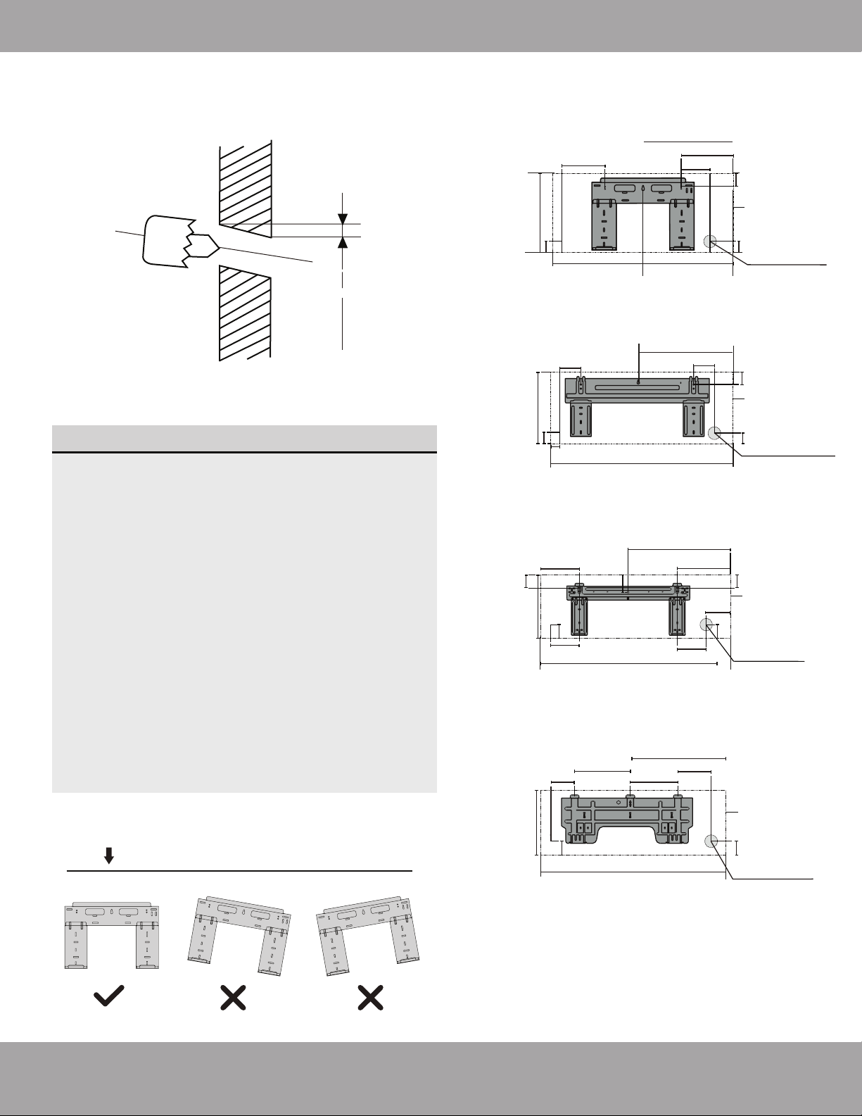
MOUNTING PLATE DIMENSIONS
Different models have different mounting plates.
In order to ensure that you have ample room to
mount the indoor unit, the diagrams to the right
show different types of mounting plates along
with the following dimensions:
• Width of mounting plate
• Height of mounting plate
• Width of indoor unit relative to plate
• Height of indoor unit relative to plate
• Recommended position of wall hole (both to
the left and right of mounting plate)
• Relative distances between screw holes
Fig. 5.3
Series 12K Models
192mm (7.55in)
232mm (9.15in)
128mm (5.05in)
43mm (1.7in)
297mm (11.7in)
Right rear wall
hole 90mm (3.5in)
Indoor unit outline
Series 18K Models
802mm (31.6in)
965mm (38in)
1080mm (42.5in)
1259mm (49.55in)
43mm (1.7in)
43mm (1.7in)
144mm (5.65in)
58mm (2.3in)
319mm (12.55in)
57mm (2.25in)
40mm (1.55in)
Right rear wall
hole 90mm (3.5in)
Series 24K Models
138mm (5.45in)
34mm
(1.35in)
Indoor unit outline
219mm (8.6in)
553mm (21.77in)
643.6mm (25.3in)
300mm (11.8in)
335mm (13.2in)
Right rear wall
hole 90mm (3.5in)
Series 36K Models
53.5mm
(2.1in)
47mm (1.85in)
76mm(3in)
53.5mm (2.1in)
47mm (1.85in)
148.7mm
(5.85in)
151mm (5.95in)
174.3mm (6.85in)
Indoor unit outline
172mm (6.8in)
362mm (14.25in)
Right rear wall
hole 90mm (3.5in)
389mm (15.3in)
52mm (2.05in)
332mm (13.05in)
257mm (10.1in)
52mm (2.05in)
Indoor unit outline
426mm(16.8in)
517.4mm(20.37in)
Correct orientation of Mounting Plate
Page 20mrcool.com
Indoor Unit Installation
Move to left or right
Fig. 5.10
1.2-1.95in
(30-50mm)
1.2-1.95in
(30-50mm)
Indoor Unit
Installation
CAUTION
Dents in the piping will affect performance. If you dent or damage the piping, cease
manipulation immediately and contact MRCOOL technical support at (270) 366-0457.
Be extremely careful not to dent or damage the piping while bending them away from the unit.
Fig. 5.4
Keep in mind that the hooks on the mounting
plate are smaller than the holes on the back
of the unit. If you find that you don’t have
ample room to connect embedded pipes to
the indoor unit, the unit can be adjusted left
or right by about 30-50mm (1.25-1.95in),
depending on the model.
UNIT IS ADJUSTABLE
Step 4: Prepare refrigerant piping
The refrigerant piping is inside an insulating sleeve
attached to the back of the unit. You must prepare
the piping before passing it through the hole in the
wall. Refer to the Refrigerant Piping Connection
section of this manual for detailed instructions on
torque requirements, technique, etc.
1. The piping will exit the unit from the right size of
the air handler.
2. Connect the indoor refrigerant piping to the
connective piping that will join the indoor and
outdoor units.
3. Based on the position of the wall hole relative to
the mounting plate, determine the necessary angle
of your piping.
4. Grip the refrigerant piping at the base of the bend.
5. Slowly, with even pressure, bend the piping
towards the hole. DO NOT dent or damage the
piping during the process.
NOTE ON PIPING ANGLE
Refrigerant piping should exit the indoor
unit from the right-hand side:
Refer to Fig. 5.4 for details.
Page 21 mrcool.com
Indoor Unit Installation
5.1 Tools Needed
You will require the following tools to carry out this
installation work correctly:
•1x crescent wrench, 19 mm
•1x crescent wrench, 22 mm/24mm
•1x crescent wrench, 24 mm/27mm
•1x Allen key, 5 mm
•1x Philips screwdriver
•1x leak detection spray or alternatively soap suds
(water/detergent mix)
5.2 Important Information
•Follow the detailed instructions for connecting the
refrigerant pipes to the indoor unit and outdoor unit.
We can only provide a warranty if the lines are
installed correctly as described in the instructions.
•If you are using a 24K Air Handler with a 4-zone
condenser, you will need to use the lineset adapter kit
that is included with the 4-zone condenser for that
lineset connection.
Step 5: Connect Refrigerant Piping to Indoor Unit Refrigerant Pipe Connectors (both ends):
If the screw connections are tightened with too little
torque, they will leak. If they are tightened with too
much torque, the screw connections may suffer
damage. Please refer to the torque requirements
section for more information. If you are not confident
about connecting the refrigerant line connectors
yourself, it is imperative that you contact the MRCOOL
®
customer service team or a professional for assistance.
IMPORTANT:
The EQ valves are only designed for one-time
installation. Their seal can not be guaranteed if they are
installed on more than one occasion. This will also void
the warranty.
5.3 Connecting the refrigerant pipes to the
indoor unit
1.
Do not remove the plastic seals from the indoor
equipment and the appropriate refrigerant pipe
until immediately before you connect them.
2. Align the refrigerant pipes correctly, make sure
the dimensions of the connecting refrigerant pipe
are the same. Place the screw connector on the
refrigerant pipes just on to the thread on the
indoor equipment and tighten the first few
threads by hand.
IMPORTANT:
Before you continue, it is essential that you read
the following instructions carefully.
•DO NOT remove the sealing caps and stoppers until
immediately before you install the lines.
•To prevent leaks, ensure that the quick-release screw
connections are absolutely free of dirt. Moisture or
foreign bodies will adversely affect the function of the
quick-release connectors, leading to a risk of
refrigerant loss (not covered by the warranty).
•Only install refrigerant lines outdoors in dry weather.
•The refrigerant lines must not be plastered over after
installation.
•Please make sure that refrigerant is never allowed to
enter the environment. Improper handling of
refrigerant may be harmful to health. Always wear
work gloves and goggles when handling refrigerant.
•Do not smoke during installation work. The equipment
must never be operated without refrigerant lines
connected; otherwise, the equipment will be damaged
immediately.
•The screw connections may only be tightened using
appropriate open ended (i.e. crescent or adjustable)
wrenches.
•Remove the plastic side panel to
access the lineset connectors.
•Remove the connector at the
bottom by unthreading by hand
and then replace with the
adapter. This will allow the fitting
to work with the 24K air handler.
Line Set Adapter Kit
Page 22mrcool.com
Indoor Unit Installation
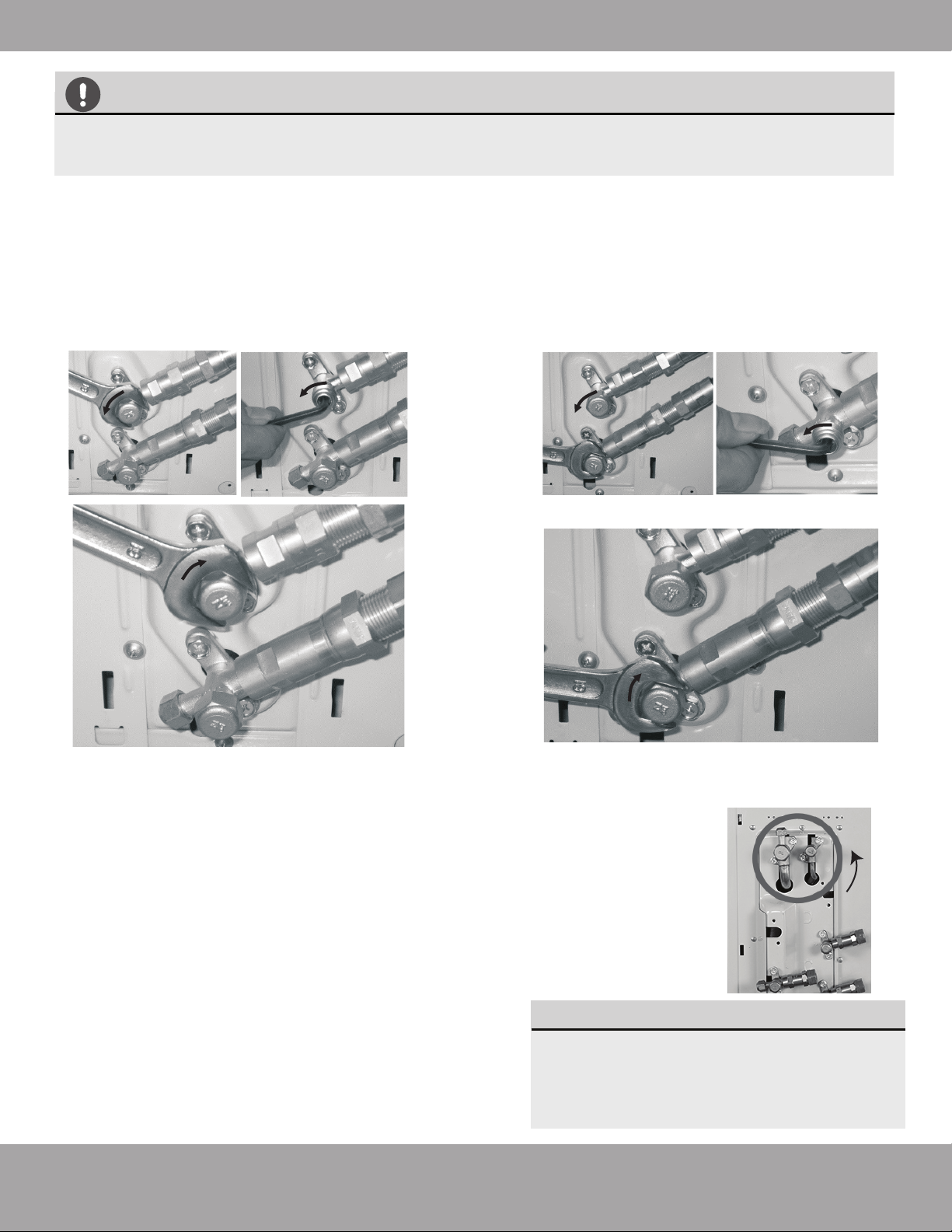
3. Using open ended wrenches (i.e. crescent or adjustable),
hold the points marked “1” and turn the nuts only at the
points marked “2” (select the appropriate wrench according
to the dimensions of the connector).
Outer Diameter
of Pipe (in/mm)
Stamp
Tightening Torque
(lb·ft / N·m)
Add. Tightening Torque
(lb·ft / N·m )
Ø0.25” (Ø 6.35mm)
1/4”
3/8”
1/2”
5/8”
11 lb•ft (14.91 N·m)
11.8lb•ft (16 N·m)
Ø0.375” (Ø 9.52mm)
18.4 lb•ft (24.95 N·m)
19.18lb•ft (26 N·m)
Ø0.5” (Ø12.7mm)
25.8 lb•ft (34.98 N·m)
26.55lb•ft (36 N·m)
Ø0.63” (Ø16mm) 33.19 lb•ft (45 N·m) 34.67lb•ft (47.01N·m)
TORQUE REQUIREMENTS
1. Excessive force can break the nut or damage the refrigerant piping. You must not exceed torque
requirements shown in the table below.
2. You can find the Outer Pipe Diameter stamped (in inches) on the valve set of the condenser.
Refer to this when finding and applying the torque values in the table below.
3. Note that there may be differences in Torque Wrenches (i.e. automotive torque wrench versus a
HVAC torque wrench) and that a socket style wrench cannot be used here.
4. Ensure that the screw connectors do not skew as you
tighten them and work quickly.
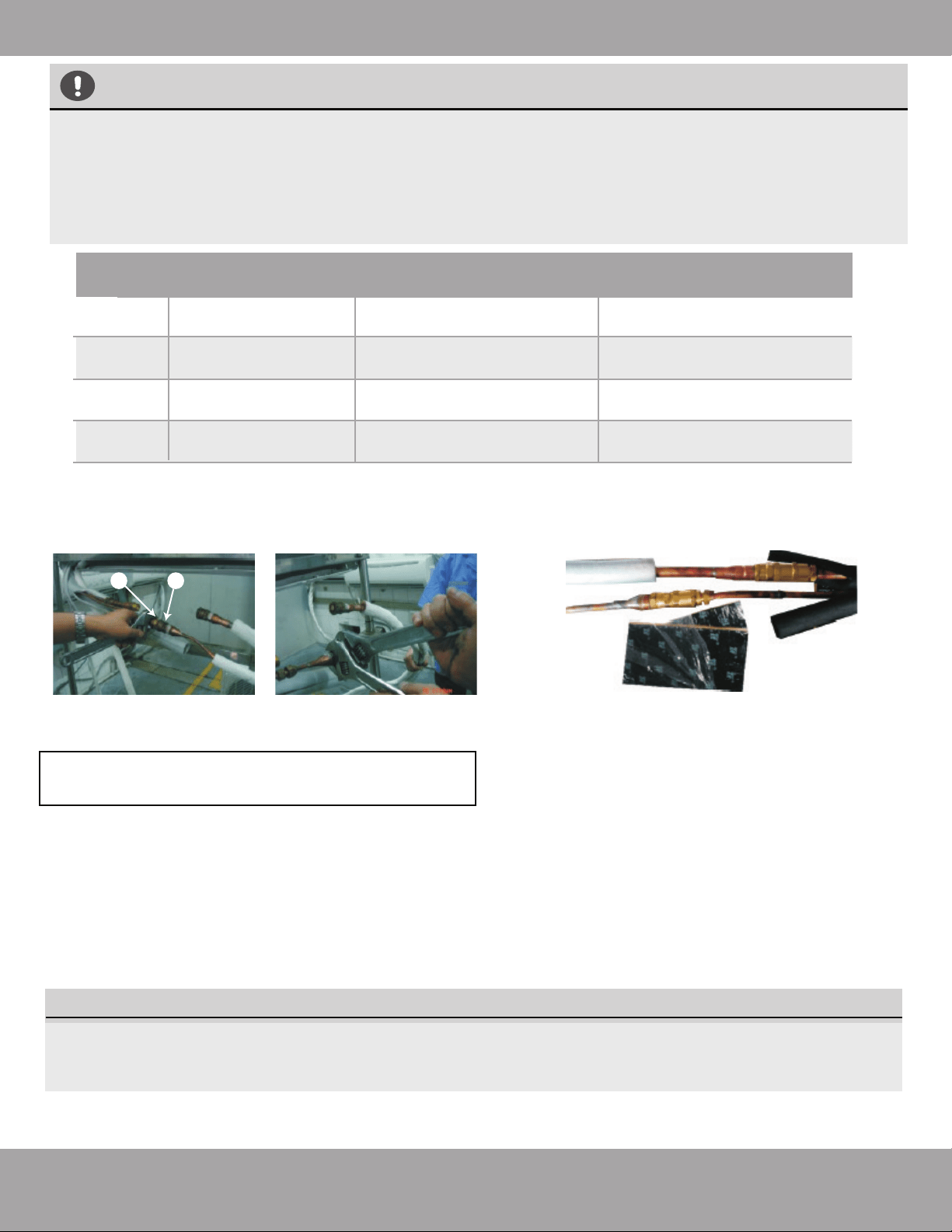
5. After finishing the connection, use the tape to wrap the
refrigerant pipe and connecting cable together.
6. After you finish connecting the quick connectors, pass the
drain hose and refrigerant pipes through the wall hole as
shown here.
7 In order to prevent Quick Connect® parts from
being exposed to air, sound deadening pads
should be used during the installation.
8.Wrap the Quick Connect
®
with the sound
deadening pads, pack down the pads tightly as
shown here.
9. Wrap up the Quick Connect
®
with the black insulation
material. For the top exposed part, use the white
insulation material (supplied in Accessories box) to wrap
completely as shown here.
10. Lastly, use tape to wrap the refrigerant pipe and
connecting cable together.
IMPORTANT: Before you continue, it is essential
that you read the following instructions carefully.
The Quick Connect
®
must be placed outside of the room. Using the wall hole sleeve, cap and neoprene to seal the
wall hole. Both power cable and signal cable should be protected by conduit.
NOTE:
1 2
Page 23
mrcool.com
Indoor Unit Installation
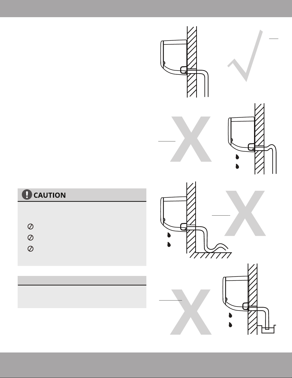
Step 6: Connect drain hose
By default, the drain hose is attached to the left-hand
side of unit (when you’re facing the back of the unit).
However, it can also be attached to the right-hand side.
NOTE ON DRAIN HOSE PLACEMENT
Make sure to arrange the drain hose according
to Fig. 5.5a.
DO NOT kink the drain hose.
DO NOT create a water trap.
DO NOT put the end of drain hose in water
or a container that will collect water.
ENSURE UNUSED DRAIN HOLE IS PLUGGED
To ensure proper drainage, the drain hose must exit
the unit on the same side as the refrigerant piping.
1.
Wrap the connection point firmly with included tape
to ensure a good seal and to prevent leaks.
2.
For the portion of the drain hose that will remain
indoors, wrap it with included insulation material to
prevent condensation.
3.
Remove the air filter and pour a small amount of
water into the drain pan to make sure that water
flows from the unit smoothly.
4.
To prevent unwanted leaks, be sure that the
factory installed rubber plug is in the unused
drain hole.
Fig. 5.5a
Fig. 5.5b
Fig. 5.5c
Fig. 5.5d
Make sure there are NO
kinks or dents in the
hose to ensure proper
drainage.
NOT CORRECT
Dents in the drain hose
will create water traps.
NOT CORRECT
Kinks in the drain hose
will create water traps.
NOT CORRECT
DO NOT place the end
of the drain hose in
water or in containers
that collect water.
This will prevent
proper drainage.
Page 24mrcool.com
Indoor Unit Installation
SIGNAL CABLE PROTECTION
The signal cable must be protected by conduit
before being pushed through the wall hole.
2. Using vinyl tape, attach the drain hose
to the underside of the refrigerant pipes.
3. Using insulation tape, wrap the refrigerant pipes
and drain hose tightly together. See Fig. 5.7 for
example. Double-check that all items are bundled in
accordance with Fig. 5.6.
DO NOT WRAP ENDS OF PIPING
When wrapping the bundle, keep the ends of
the piping unwrapped. You need to access them
to test for leaks at the end of the installation
process (refer to Electrical Checks and Leak
Checks section of this manual).
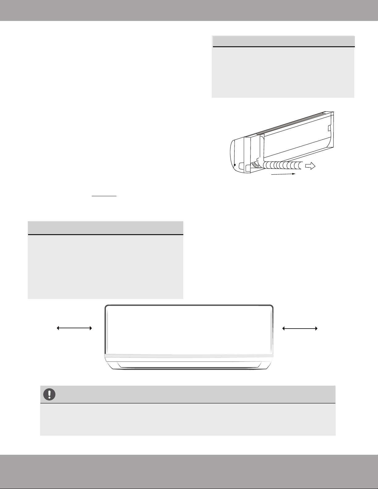
Step 8: Mount indoor unit
Step 7: Wrap piping and cables
Before passing the piping, drain hose, and signal cable
through the wall hole, you must bundle the piping and drain
hose together and tightly wrap them together with the
provided tape. The signal wire needs to be protected by
conduit.
1. Bundle the drain hose and refrigerant pipes
according to Fig. 5.6.
DRAIN HOSE MUST BE ON BOTTOM
Make sure that the drain hose is at the bottom
of the bundle. Putting the drain hose at the
top of the bundle can cause the drain pan to
overflow, which may lead to fire or water
damage.
Indoor Unit
Space behind unit
Refrigerant piping
Drain hose
Insulation tape
Fig. 5.6
Fig. 5.7
If you installed new connective piping to the
outdoor unit, do the following:
If you have already passed the refrigerant piping
through the hole in the wall, proceed to Step 4.
Otherwise, double-check that the ends of the
refrigerant pipes are sealed to prevent dirt or
foreign material from entering the pipes.
Slowly pass the wrapped bundle of refrigerant
pipes and drain hose as well as the signal wire
(protected by conduit) through the hole in the wall.
Hook the top of the indoor unit on the upper
hook of the mounting plate.
Check that unit is hooked firmly on mounting
plate by applying slight pressure to the left and
right-hand sides of the unit. The unit should not
jiggle or shift.
Using even pressure, push down on the bottom
half of the unit. Keep pushing down until the unit
snaps onto the hooks along the bottom of the
mounting plate.
Again, check that the unit is firmly mounted by
applying slight pressure to the left and the
right-hand sides of the unit.
1.
2.
3.
4.
5.
6.
7.
Page 25 mrcool.com
Indoor Unit Installation
Installation Instructions –
Outdoor Unit
Step 1: Select installation location
Before installing the outdoor unit, you must
choose an appropriate location. The following
standards will help you choose an
appropriate location.
Proper installation locations meet the
following standards:
Meets all spatial requirements shown in
Installation Space Requirements (Fig. 6.1)
Good air circulation and ventilation
Firm and solid location that can support
the unit and will not cause vibration
Noise from the unit will not disturb others
Protected from prolonged periods of direct
sunlight or rain
DO NOT install unit in the following locations:
Near an obstacle that will block air inlets and
outlets
Near a public street, crowded areas, or
where noise from the unit will disturb others
Near animals or plants that will be harmed
by hot air discharge
Near any source of combustible gas in a
location that is exposed to large amounts of
dust
In a location exposed to a excessive
amounts of salty air
In a location that exposes the unit to large
amounts of forced water
Fig. 6.1
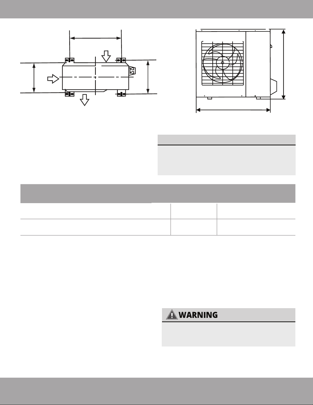
Ground Installed:
12 in (30 cm)
Bracket Installed:
6 in (15 cm)
clearance between
back and wall
79in (200cm)
in front
12in (30cm)
on left
24in (60cm)
above
24in (60cm)
on right
79in (200cm)
in front
12in (30cm)
on left
24in (60cm)
above
24in (60cm)
on right
6
Outdoor Unit Installation
Page 26mrcool.com
Outdoor Unit Installation
SPECIAL CONSIDERATIONS FOR
EXTREME WEATHER
If the unit is exposed to heavy wind:
Install unit so that air outlet fan is at a 90°
angle to the direction of the wind. If
needed, build a barrier in front of the unit
to protect it from extremely heavy winds.
Ensure the wind barrier does not block
necessary air flow. See Fig. 6.2 and
Fig. 6.3 below.
If the unit is frequently exposed to
heavy rain or snow:
Build a shelter above the unit to protect
it from the rain or snow. Be careful not to
obstruct air flow around the unit.
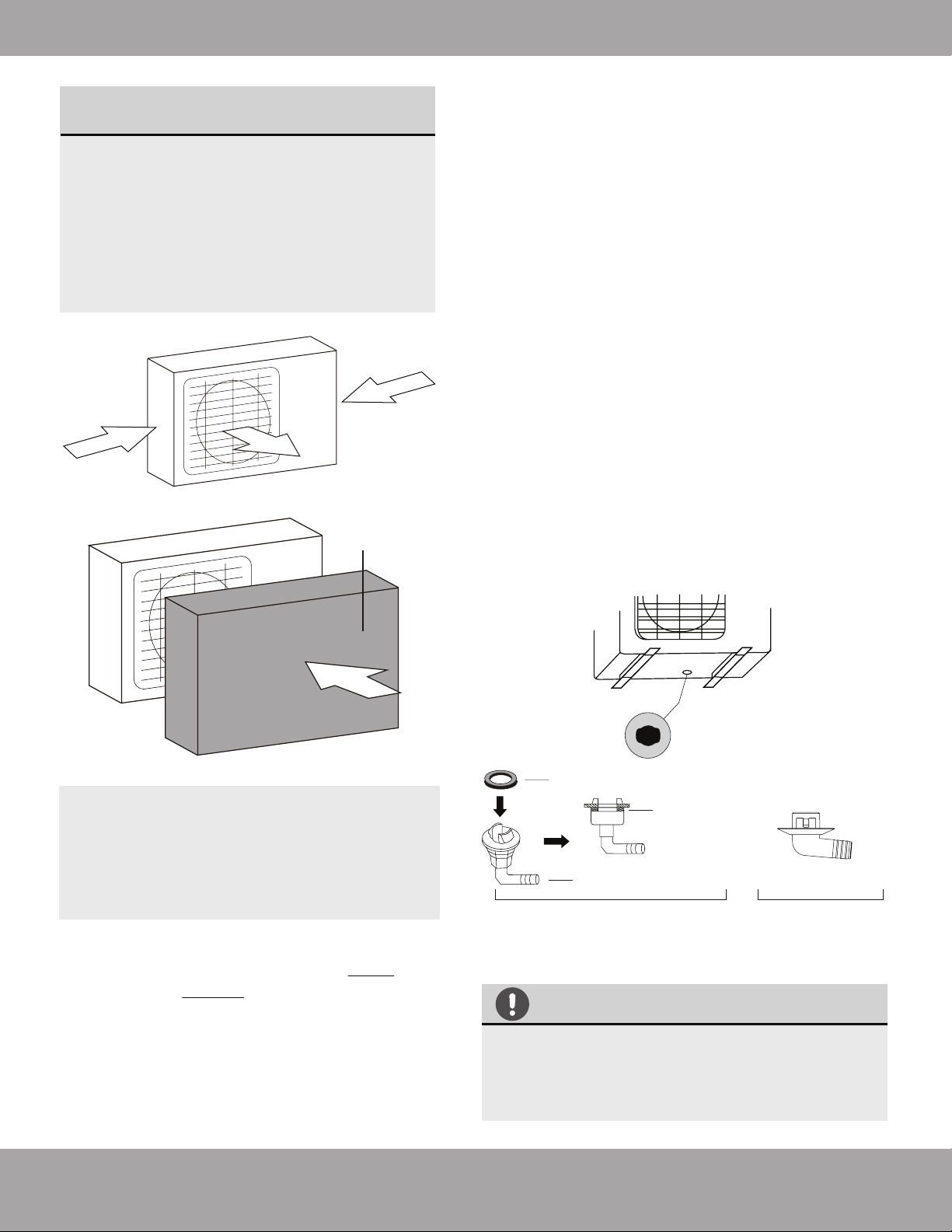
Step 2: Install drain joint
Heat pump units require a drain joint ONLY if the
unit is elevated. DO NOT install if the unit is sitting
on the ground or concrete pad.
Before bolting the outdoor unit in place, you must
install the drain joint at the bottom of the unit.
Note that there are two different types of drain
joints depending on the type of outdoor unit.
Strong wind
Strong wind
Fig. 6.2
Fig. 6.3
Strong wind
Wind Baffle
IN COLD CLIMATES
In cold climates, make sure that the drain
hose is as vertical as possible to ensure swift
water drainage. If water drains too slowly, it
can freeze.
Seal
Drain joint (only use if elevated)
(A) (B)
Base pan hole of
outdoor unit
Seal
Fig. 6.4
If the drain joint comes with a rubber seal
(see Fig. 6.4 - A), do the following:
1. Fit the rubber seal on the end of the drain joint that
will connect to the outdoor unit.
2. Insert the drain joint into the hole in the base pan of
the unit.
3. Rotate the drain joint 90° until it clicks in place
facing the front of the unit.
4. Connect a drain hose extension (not included) to
the drain joint to redirect water from the unit during
heating mode.
If the drain joint doesn’t come with a rubber seal
(see Fig. 6.4 - B), do the following:
1. Insert the drain joint into the hole in the base pan
of the unit. The drain joint will click in place.
2. Connect a drain hose extension (not included) to
the drain joint to redirect water from the unit during
heating mode.
Page 27
mrcool.com
Outdoor Unit Installation
Outdoor Unit Dimensions (inches)
Width (W) x Height (H) x Depth (D)
Mounting Dimensions (inches)
Width (A) Depth (B)
37.24 x 31.89 x 16.54 (inches)
946 x 810 x 420 mm
26.5 in.
673 mm
15.87 in.
403 mm
37.24 x 31.89 x 16.54 (inches)
946 x 810 x 420 mm
26.5 in.
673 mm
15.87 in.
403 mm
DIY-MULTI3-27HP230
DIY-MULTI4-36HP230
WHEN DRILLING INTO CONCRETE,
EYE PROTECTION IS RECOMMENDED
AT ALL TIMES.
W
H
D
Air Inlet
A
B
Air Outlet
Air Inlet
Fig. 6.5
If you install the unit on the ground or on a
concrete mounting platform, do the following:
1. Mark the positions for four expansion bolts based
on dimensions in the Unit Mounting Dimensions
chart.
2. Pre-drill holes for expansion bolts.
3. Clean concrete dust away from holes.
4. Place a nut on the end of each expansion bolt.
5. Hammer expansion bolts into the pre-drilled
holes.
Step 3: Anchor outdoor unit
The outdoor unit can be anchored to the ground
or to a wall-mounted bracket.
UNIT MOUNTING DIMENSIONS
See below for the multi-zone condenser
sizes and the distance between their
mounting feet. Prepare the installation base
of the unit according to the dimensions below.
6. Remove the nuts from expansion bolts, and
place outdoor unit on bolts.
7. Put washer on each expansion bolt, then
replace the nuts.
8. Using a wrench, tighten each nut until snug.
Page 28
mrcool.com
Outdoor Unit Installation
If you install the unit on a wall-mounted bracket, do the following:
TO REDUCE VIBRATION OF WALL-
MOUNTED UNIT
Before installing a wall-mounted unit, make sure that the wall is made of solid brick,
concrete, or of similarly strong material. The wall must be able to support at least four
times the weight of the unit.
1. Mark the position of bracket holes based on
dimensions in the Unit Mounting Dimensions chart.
2. Pre-drill the holes for the expansion bolts.
3. Clean dust and debris away from holes.
4. Place a washer and nut on the end of each
expansion bolt.
5. Thread expansion bolts through holes in mounting
brackets, put mounting brackets in position, and
hammer expansion bolts into the wall.
6. Check that the mounting brackets are level.
7. Carefully lift unit and place its mounting feet on
brackets.
8. Bolt the unit firmly to the brackets.
If allowed, you can install the wall-mounted
unit with rubber gaskets to reduce
vibration and noise.
Indoor Air Handler Compatability with Multi-Zone Condensers
Connective Pipe Size for Indoor Air Handlers
OUTDOOR CONDENSER | DIY-MULTI3-27HP230
OUTDOOR CONDENSER | DIY-MULTI4-36HP230
DIY-09-HP-WMAH-230B
DIY-09-HP-WMAH-230B
DIY-12-HP-WMAH-230B
DIY-12-HP-WMAH-230B
DIY-18-HP-WMAH-230B
DIY-18-HP-WMAH-230B
DIY-24-HP-WMAH-230B
(Only 1 per Condenser)
LIQUID
INDOOR UNIT CAPACITY (Btu/h)
GAS
9K/12K/18K
24K/36K
1/4
3/8
1/2
5/8
Page 29
mrcool.com
Outdoor Unit Installation
Refrigerant Piping Connection
6
Connecting the refrigerant pipe to outdoor unit
CAUTION
For your safety, always wear goggles and work gloves when connecting the pipes.
7
Refrigerant Piping Connection
NOTE
To distinguish the connectors to be connected to the indoor unit and outdoor unit, the
connectors of the refrigerant pipe have been labelled “A”,“B”,“C”and “D”. Ensure the marks on
the connector are the same to the indoor’s and outdoor’s respectively during connection.
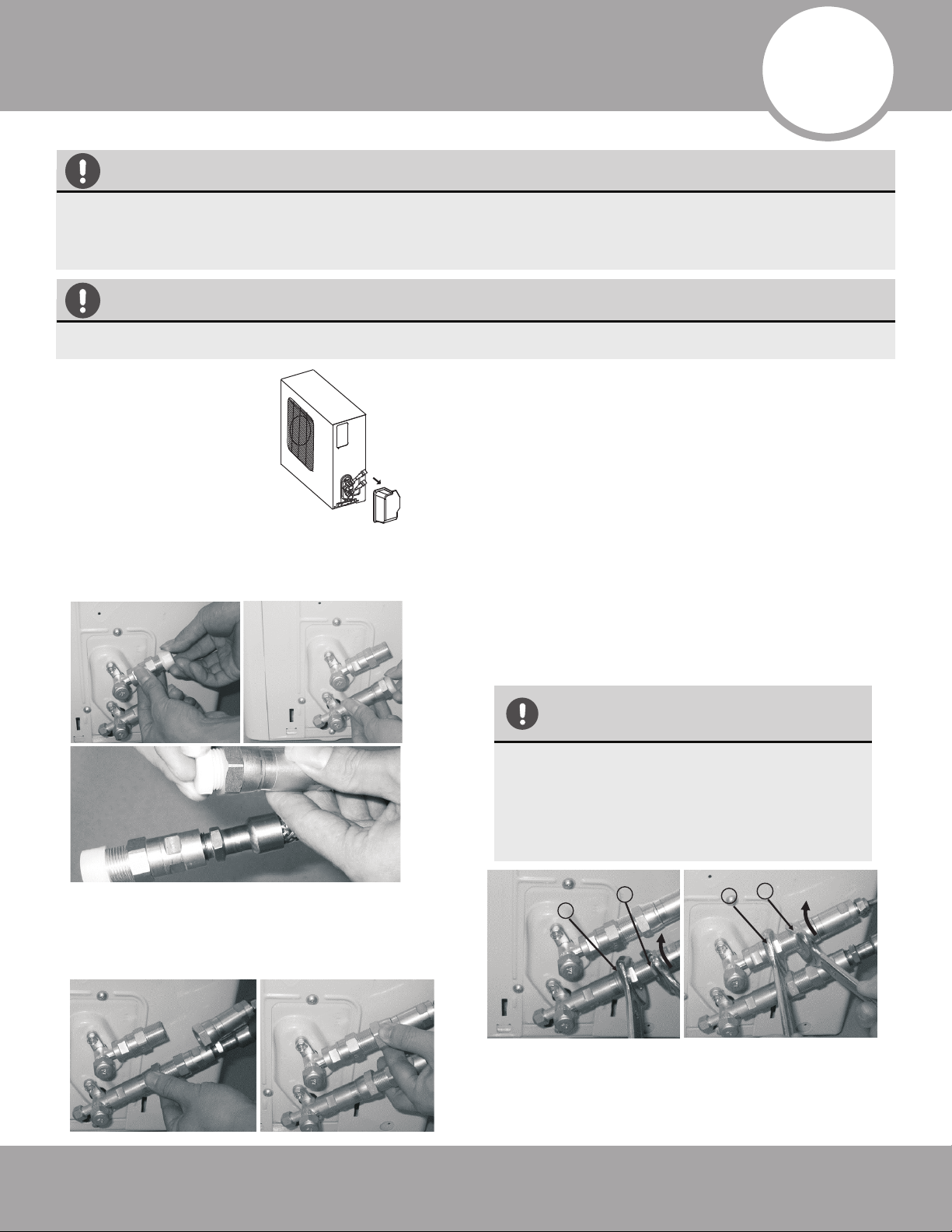
1. First remove the
water tray on the
outdoor unit as
shown.
2. Do not remove the plastic seals from the
outdoor unit and the appropriate
refrigerant pipes until immediately before
you connect them.
NOTE: The refrigerant pipes must be connected to the
valves on the outdoor unit with as little stress as
possible.
IMPORTANT: Before you continue, it is essential that
you read the following instructions carefully.
3. Align the refrigerant pipes correctly so that they line
up with the valves and are not stressed. Place the
screw connector on the refrigerant line just on to the
thread on the outdoor unit and tighten the first few
threads by hand.
4. Now tighten the bottom screw connector first and
then the top screw connector using the open ended
wrench (i.e. crescent or adjustable). Using the wrench,
hold the points marked “1” and turn the nuts only at
the points marked “2” (Select the appropriate wrench
according to the dimensions of the connector).
Ensure that the screw connectors do not skew as you
tighten them and work quickly. See below for the
proper torque requirements.
After completing steps 1- 4, check that all the
connections are sealed correctly using leak detection
spray or soap suds. If any bubbles form, the system
has a leak and the screw connectors must be
retightened using a crescent or adjustable wrench.
IMPORTANT
Since the coupling works with tapping
rings, it may leak if you undo and
reconnect the pipes. This will also
void the warranty.
1
1
2
2
Page 30
mrcool.com
Refrigerant Piping Connection
Fig. 7.1
≥4in (10cm)
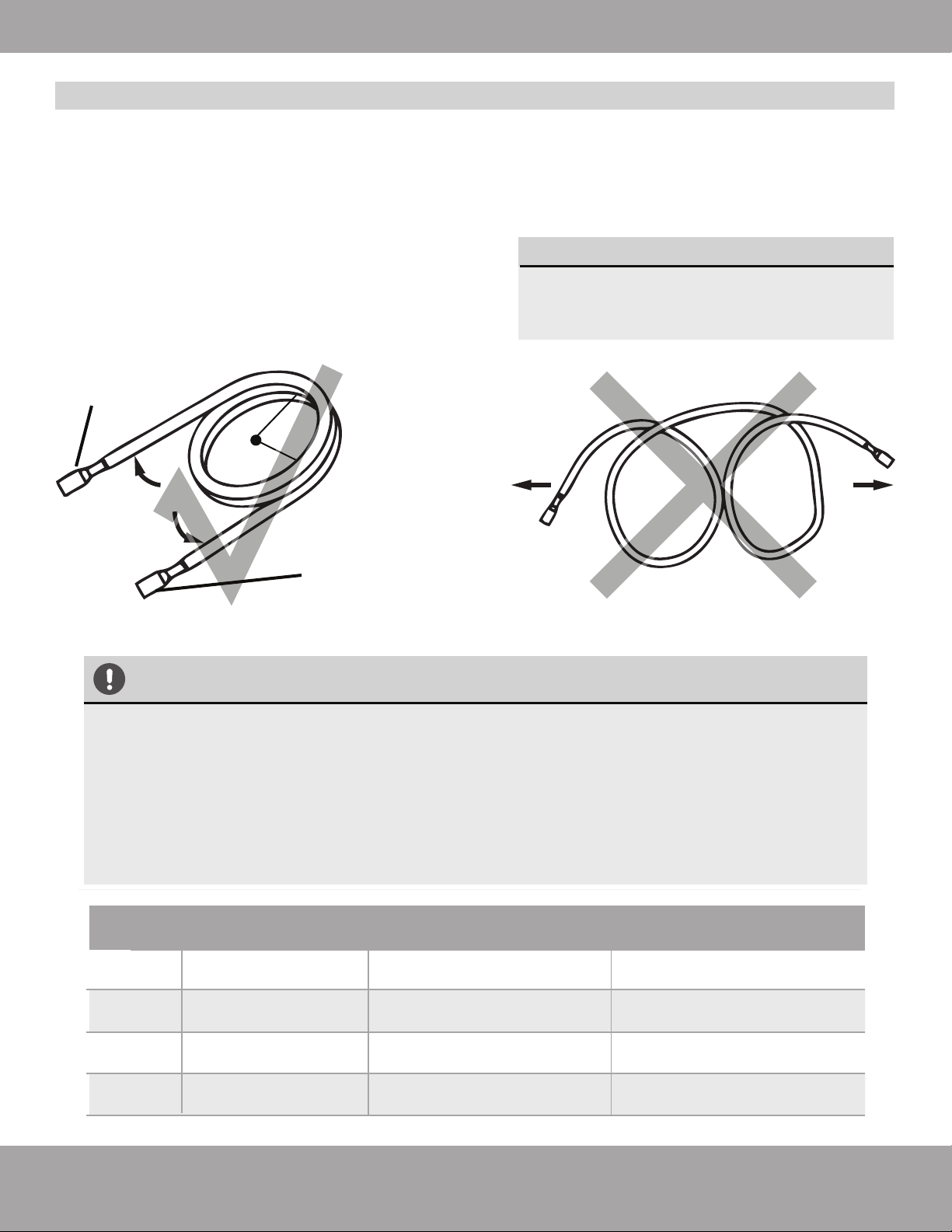
Carefully unroll to indoor
handler connection
Connect directly to
exterior condensor
Keep excess coiled
Radius
1. Use your hands to slowly unwind the copper piping (Quick Connect
®
line set). Only unwind as much as
necessary for use.
2. If the pipe is repeatedly bent or extended, it will become hard and difficult to manipulate. Avoid bending
or extending the pipe for more than 3 times.
3. Do not bend the pipe excessively, otherwise it will break.
Refer to
Fig. 7.1
MINIMUM BEND RADIUS
When bending connective refrigerant
piping, the minimum bending radius is
a 10cm. Refer to Fig. 7.1
Extend the pipe by unwinding it
TORQUE REQUIREMENTS
1. Excessive force can break the nut or damage the refrigerant piping. You must not exceed
torque requirements shown in the table below.
2. You can find the Outer Pipe Diameter stamped (in inches) on the valve set of the con-
denser. Refer to this when finding and applying the torque values in the table below.
3. Note that there may be differences in Torque Wrenches (i.e. automotive torque wrench
versus a HVAC torque wrench) and that a socket style wrench cannot be used here.
Outer Diameter
of Pipe (in/mm)
Stamp
Tightening Torque
(lb·ft / N·m)
Add. Tightening Torque
(lb·ft / N·m )
Ø0.25” (Ø 6.35mm)
1/4”
3/8”
1/2”
5/8”
11 lb•ft (14.91 N·m)
11.8lb•ft (16 N·m)
Ø0.375” (Ø 9.52mm)
18.4 lb•ft (24.95 N·m)
19.18lb•ft (26 N·m)
Ø0.5” (Ø12.7mm)
25.8 lb•ft (34.98 N·m)
26.55lb•ft (36 N·m)
Ø0.63” (Ø16mm) 33.19 lb•ft (45 N·m) 34.67lb•ft (47.01N·m)
5. Now remove the cover on the top refrigerant connection
valve using a 19 mm open ended wrench (i.e. crescent or
adjustable). Open the valve by turning it counter-clockwise as
far as it will go using a 5 mm Allen key. The valve is now open.
If the valve is not opened fully, the system may malfunction
and suffer damage. Screw the cover back on to the top valve
and tighten it well to ensure that it is properly sealed.
CAUTION
Page 31
mrcool.com
Refrigerant Piping Connection
6. Now remove the cover on the bottom valve using a 19
mm crescent (or adjustable) wrench. Open the valve by
turning it counter-clockwise as far as it will go using a 5
mm Allen key. The valve is now open. If the valve is not
opened fully, the system may malfunction and suffer
damage. Screw the cover back on to the bottom valve
and tighten it well to ensure that it is properly sealed.
7. After completing steps 1- 6, repeat steps 2-6 for each lineset. Check that all of the connections are sealed correctly
using leak detection spray or soap suds. If any bubbles form, the system has a leak and the screw connectors must be
retightened using a crescent or adjustable wrench.
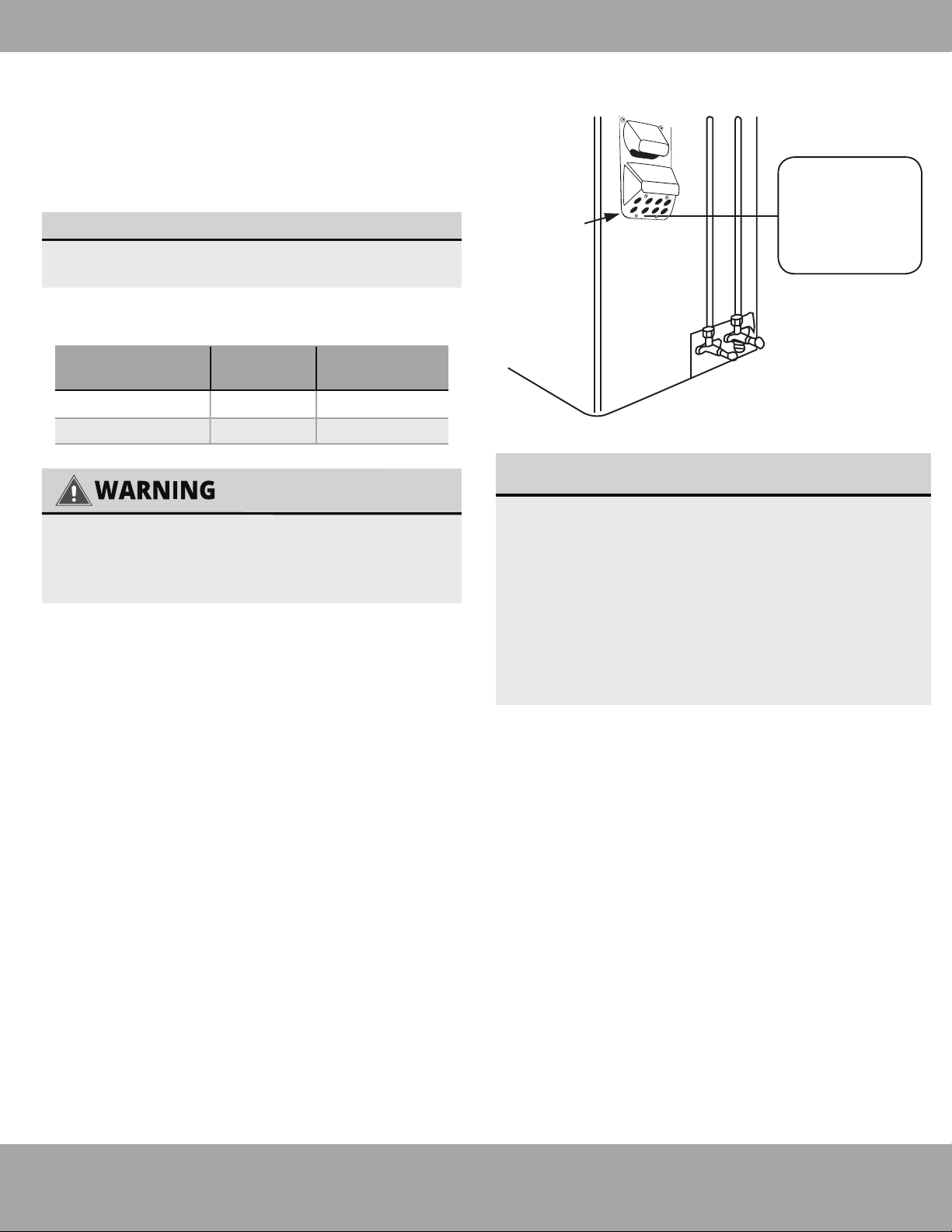
8. After opening all of the lineset connection valves, you must also open the two main valves
(King Valve) as indicated after installation is complete. To do this, remove the plastic caps,
and turn counter clockwise with a 5mm allen wrench.
9. Start the equipment so that the operating pressures build
up inside the system. Check all the connectors again for
signs of leaks
a) during cooling mode
b) in heating mode.
NOTE
If any bubbles form, the system has a
leak and the screw connectors must be
retightened.
All of these steps must be completed BEFORE powering on the unit. Failing to do so
could damage the unit.
Refrigerant Piping
Signal Cable
(inside conduit)
Drainage Pipe
Outdoor Unit (Exterior / Condenser)
Quick Connect
®
connections
Page 32
mrcool.com
Refrigerant Piping Connection
8
Electrical Connections
Page 33 mrcool.com
BEFORE PERFORMING ANY ELECTRICAL WORK, TURN OFF ALL POWER TO THE SYSTEM.
Note that wire colors of this series / model may differ from previous models, other series and general
conventions.
All wiring must be performed in accordance with the wiring diagrams shown in Fig. 7.1 and
demonstrated in the images
below.
DO NOT MIX UP LIVE AND NULL WIRES
This is dangerous and can cause the air conditioning unit to malfunction. Make sure you clearly distinguish the
Live (”L”) Wires from the other wires.
All wiring must be performed in accordance with the wiring diagrams shown in Fig. 7.1 and demonstrated in the
images shown here.
BEFORE PERFORMING ELECTRICAL WORK, READ THESE REGULATIONS
1.
All wiring must comply with local and national electrical codes.
2. All electrical connections must be made according to the Electrical Connection Diagram located on the
panels of the indoor and outdoor units.
3. If there is a serious safety issue with the power supply, stop work immediately. Explain your reasoning
to the client, and refuse to install the unit until the safety issue is properly resolved.
4. Power voltage should be within 90-100% of rated voltage. Insufficient power supply can cause
malfunction, electrical shock, or fire.
5. Circuit, including any switches, should have a capacity 1.5 times the maximum unit current (amps).
6. A qualified electrician must use an approved circuit breaker or switch that disconnects all poles and has
a contact separation of at least 1/8in (3mm).
7. Do not connect another appliance to the same circuit.
8. Make sure to properly ground the air conditioner.
9. Every wire must be firmly connected. Loose wiring can cause the terminal to overheat, resulting in
malfunction and possible fire. Double check that the screws are tightly fastened.
10. Do not let wires touch or rest against refrigerant tubing, the compressor, or any moving parts within the
unit.
11. If the unit has an auxiliary electric heater, it must be installed at least 40in (1 meter) away from
combustible materials.
12. To avoid getting an electric shock, never touch the electrical components soon after the power supply
has been turned off. After turning off the power, always wait 10 minutes or more before you touch the
electrical components.
13. Make sure that you do not cross your electrical wiring with your signal wiring. This may cause distortion
and interference.
14. The unit must be connected to the main outlet. Normally, the power supply must have an impedance of
32 ohms.
15. Connect the outdoor wires before connecting the indoor wires.
Cover
Outdoor Unit
Wiring Diagram
is located on
the inside of the
wire cover on
the outdoor unit.
Fig. 8.2
Page 34
mrcool.com
Electrical Connections
Appliance
Amps(A)
AWG
35
45
8
6
27K
36K
Model Series
Minimum Wire Gauge
for Power Cables
USE THE RIGHT CABLE
• See table below for gauge requirements
ALL WIRING MUST BE PERFORMED STRICTLY
IN ACCORDANCE WITH THE WIRING
DIAGRAM LOCATED AS SHOWN IN FIG 8.2.
1.
Unscrew the electrical wiring cover and remove it.
2.
Unscrew the cable clamp below the terminal block
and place it to the side.
3.
Match the wire colors / labels with the labels on
the terminal block, and firmly screw the u-lug of each
wire to its corresponding terminal.
4.
After checking to make sure every connection is
secure, loop the wires around to prevent rain water
from flowing into the terminal.
5.
Using the cable clamp, fasten the cable to the
unit. Screw the cable clamp down tightly.
6.
Insulate unused wires with PVC electrical tape.
Arrange them so that they do not touch any electrical
or metal parts.
7.
Replace the wire cover on the side of the unit, and
screw it in place.
The air conditioner’s circuit board (PCB) is
designed with a fuse to provide overcurrent
protection. The specifications of the fuse are
printed on the circuit board.
EXAMPLE Indoor unit: T3.15AL/250VAC,
T5AL/250VAC, T3.15A/250VAC, T5A/250VAC, etc.
EXAMPLE Outdoor unit:
T20A/250VAC(<=18000Btu/h units),
T30A/250VAC(>18000Btu/h units), etc.
NOTE ABOUT FUSE SPECIFICATIONS
Connect signal and power cables
The outside unit’s terminal block is protected by an
electrical wiring cover on the side of the unit. A com-
prehensive wiring diagram is printed on the inside of
the wiring cover.
Page 35
mrcool.com
Electrical Connections
CAUTION
Electrical work must be completed by a qualified electrical technician.
Connect the connective cables to the terminals, as identified below, with their matching
numbers on the terminal block of the indoor and outdoor units. For example, in the US models
shown in the following diagram, Terminal L1(A) of the outdoor unit must connect with terminal
1 on the indoor unit. Continue to match zone to zone for any additional connections.
See wiring diagram below and take note of the following precautions.
• Check the specifications for the power source before proceeding.
• Confirm that the electrical capacity is sufficient.
• Confirm that the cable thickness is as specified in the power source specifications.
• Always install an earth leakage circuit breaker in wet or moist areas.
• The following can be caused by a drop in voltage; vibration of a magnetic switch, damaging
the contact point, broken fuses, and disturbance of normal functioning.
• Disconnection from a power supply must be incorporated into the fixed wiring. It must have
an air gap contact separation of at least 3mm in each active (phase) conductors.
• Before accessing terminals, all supply circuits must be disconnected.
• If using magnetic rings (optional - not supplied), you must use the correct magnetic rings on
your equipment to satisfy the EMC compulsory regulations required by the international
standard CISPR 14-1:2005/A2:2011.
NOTE
This product is designed to run on 60Hz frequency which is the North American standard.
Run the main power cord through the lower line-outlet of the cord clamp. Use a magnetic ring (not
supplied, optional part) to hitch the connective cable of indoor and outdoor units after installation.
One optional magnetic ring is used for one cable.
---- This symbol indicates field wiring.
Up to Three Zones
OPTIONAL
OPTIONAL
OPTIONAL
OPTIONAL
Up to Four Zones
L2
L1
LPPUS REWOP Y
L1(A)
L2(A)
S(A)
L1(B)
L2(B)
S(B)
1(C) 2(C) 3(C) 1(D) 2(D) 3(D)
TO A
TO B
TO D
TO C
OPTIONAL
OPTIONAL
OPTIONAL
OPTIONAL
OPTIONAL
This symbol indicates optional magnetic ring.
Page 36
mrcool.com
Refrigerant Piping Connection
AFTER PERFORMING GAS LEAK CHECKS
After confirming that all the pipe connection
points DO NOT leak, replace the valve cover
on the outside unit.
Electrical and Gas Leak Checks
8
Gas Leak Checks
WARNING – RISK OF
ELECTRIC SHOCK
ALL WIRING MUST COMPLY WITH LOCAL,
STATE, AND NATIONAL ELECTRICAL CODES,
AND MUST BE INSTALLED BY A LICENSED
ELECTRICIAN.
Electrical Safety Checks
BEFORE TEST RUN
DURING TEST RUN
After installation, confirm that all electrical wiring is
installed in accordance with local and national
regulations, and according to the Installation
Manual.
Check Grounding Work
Measure grounding resistance by visual detection
and with grounding resistance tester. Grounding
resistance must be less than 4.
Note: This may not be required for some locations
in the US.
Check for Electrical Leakage
During the Test Run, use an electroprobe and
multimeter to perform a comprehensive electrical
leakage test.
If electrical leakage is detected, turn off the unit
immediately and allow an electrician to find and
resolve the cause of the leakage.
Note: This may not be required for some locations
in the US.
There are two different methods to check for
gaseous leaks.
Soap and Water Method
Using a soft brush, apply soapy water or liquid
detergent to all pipe connection points on the
indoor unit and outdoor unit. The presence of
bubbles indicates a leak.
Leak Detector Method
If using leak detector, refer to the device’s opera-
tion manual for proper usage instructions.
9
Electrical and Gas Leak Checks
Page 37 mrcool.com
Refrigerant Piping Connection
Before Test Run
Test Run Instructions
List of Checks to Perform PASS/FAIL
Outdoor (2):
Indoor (2):
No electrical leakage
Unit is properly grounded
All electrical terminals
properly covered
Indoor and outdoor units
are solidly installed
Wall Penetration Sleeve is
packed airtight
All pipe connection points
do not leak
Water drains properly
from drain hose
All piping is properly
insulated
Unit performs COOL
function properly
Unit performs HEAT
function properly
Indoor unit louvers rotate
properly
Indoor unit responds to
remote control
You should perform the Test Run for at least
30 minutes.
1. Connect power to the unit.
2. Press the ON/OFF button on the remote
controller to turn it on.
3. Press the MODE button to scroll through the
following functions, one at a time:
• COOL – Select lowest possible temperature
• HEAT – Select highest possible temperature
4. Let each function run for 5 minutes, and perform
the following checks:
Only perform test run after you have
completed the following steps:
• Electrical Safety Checks – Confirm that
the electrical system is safe and operating
properly
• Gas Leak Checks – Check all flare nut
connections and confirm that the system is
not leaking
• Confirm that gas and liquid (high and low
pressure) valves are fully open
10
Test Run
Page 38mrcool.com
Test Run
DOUBLE-CHECK PIPE CONNECTIONS
IF AMBIENT TEMPERATURE IS BELOW
63°F (17°C)
THANK YOU
5. After the Test Run is successfully complete, and
you confirm all check points in List of Checks to
Perform have PASSED, do the following:
a. Using remote control, return unit to normal
operating temperature.
b. Using insulation tape, wrap the indoor refrigerant
pipe connections that you left uncovered during the
indoor unit installation process.
Fig. 10.1
Manual control button
During operation, the pressure of the
refrigerant circuit will increase. This may
reveal leaks that were not present during your
initial leak check. Take time during the Test
Run to double-check that all refrigerant pipe
connection points do not have leaks. Refer to
Gas Leak Check section for instructions.
You can’t use the remote controller to turn
on the COOL function when the ambient
temperature is below 63°F. In this
instance, you can use the MANUAL
CONTROL button to test the COOL
function.
1.Lift the front panel of the indoor unit,
and raise it until it clicks in place.
2.The MANUAL CONTROL button is
located on the right-hand side of the
unit. Press it 2 times to select the COOL
function. See Fig.10.1
3.Perform Test Run as normal.
Thank you for purchasing a MRCOOL
ductless mini-split heating and air
conditioning product.
MRCOOL is a young, family-owned
company, so we are truly thankful you
trusted us with your business. Should you
need any technical support or just have
questions about your MRCOOL product,
please don’t hesitate to call us at
270-366-0457.
And if you can spare a few minutes today,
a review of your new MRCOOL
®
product on
the partner site where you purchased it
would really help us out. Real reviews
from actual customers like you are
invaluable to a growing company like ours.
Again, thanks for being a valued customer!
Page 39
Troubleshooting
mrcool.com
11
NOTE: If the problem is not resolved, please contact a qualified service professional. Be sure to inform
them of the detailed malfunctions and unit model number.
NOTE: If the problem is not resolved, please contact a qualified service professional. Be sure to inform
them of the detailed malfunctions and unit model number.
The following events may occur during normal operation, and may not indicate malfunction.
Operation is
delayed after restart
Fan speed changes
- off, very slow and
then normal
Heating operation
stops suddenly and
defrost-light blinks
Mist coming out of
the indoor unit
Low volume sounds
are emitted by the
air conditioner
Dust discharges
from the unit
Emits a peculiar
odor
Changes to fan only
while cooling or
heating mode
Voltage Fluctuations
Operation is erratic,
unpredictable or
unresponsive
To prevent blowout of the fuse, the compressor will not operate while
the protection circuit is working for about 3 minutes after sudden OFF--ON
operation of the power supply.
In HEAT mode, the indoor unit temporarily stops for maximum of 10
minutes to perform the automatic defrosting operation.
May occur when air conditioner is used for the first time or has not been
used for a long time.
Various smells generated from interior textile, furniture, or cigarette smoke
absorbed into the air conditioner may be emitted. If not the case, contact a
local dealer or your installation contractor.
Room temperature reaches the temperature setting of the remote control.
If not the case, contact a local dealer or your installation contractor.
The voltage can fluctuate within 10% above or below rated voltage. During
start up, the voltage can drop within 15% of rated voltage. The voltage can
be interval unbalanced within 3% above or below rated voltage.
Interference from cell phone towers and remote boosters may cause the
unit to malfunction.
Turn power off on unit and circuit at breaker, wait 10 seconds and power on.
Press the ON/OFF button on the remote controller to restart operation.
Automatically happens in heating mode :
--prevents cold air blowing onto occupants when heating operation starts
--perform automatic defrosting operation
--perform low temperature heating operation
In COOL mode, a mist generated by condensation formed with sudden
cooling process may be emitted.
Hissing sound -- during operation or immediately after stopping the air
conditioner, refrigerant flowing sound may be heard.
Squeaking sound -- normal expansion and contraction of plastic and
metal parts caused by temperature change during the operation.
Rushing air -- when louver resets its position.
Mist may generate due to moisture from defrosting process when the air
conditioner restarts in HEAT mode operation after defrosting.
Symptom Cause
Page 40
Troubleshooting
mrcool.com
Unit will not operate
Poor cooling or
heating performance
Indicator lamps
continue flashing
Error code appears
in the indoor unit,
such as: E0,E1,E2....
P1,P2,P3.....
or F1, F2,F3.....
-- Is there a power failure?
-- Has a switch been turned off, a circuit breaker tripped or a fuse blown?
-- Is the timer operating?
-- Are the batteries used in the remote controller exhausted?
-- Are the batteries used in the remote controller loaded properly?
-- Are the air filters dirty?
-- Is air flow unrestricted in & out of indoor & outdoor units?
-- Are the temperature and mode settings correct?
-- Are the windows or doors left opened?
-- Is fan speed on high and louvers allowing maximum flow?
-- Is direct or strong sunlight shining into the room in cooling operation?
-- Is the SILENCE function activated? Under SILENCE operation,
noise reduction is prioritized and the air-conditioning performance may
become lower.
--
-- Are there other heating apparatus or computers operating, or too many
people in the room in cooling operation?
Symptom Diagnostic
The unit may stop operation or continue to run in a safety condition
(depending on models). Waiting for about 10 minutes, the fault may be
recovered automatically, if not, disconnect the power and then connect
it again. If the problem still exists, disconnect the power and contact
the nearest customer service center.
Note that the wire colors of this series / model may differ from previous models,
other series and general conventions.
All wiring must be performed in
accordance with the wiring diagrams shown in Section 8 and associated images
.
Wires and terminals are numbered to match accordingly.
WARNING
In the case of ANY of the following, turn off the unit immediately!
· Signal / power cable is damaged or abnormally warm
· Burning odor
· Loud or abnormal sounds
· A power fuse or circuit breaker trips frequently
· Water or other objects fall into or out of the unit
DO NOT ATTEMPT TO CORRECT
THESE ITEMS YOURSELF!
CONTACT A SERVICE
PROFESSIONAL IMMEDIATELY
NOTE: If the problem is not resolved, please contact a qualified service professional.
Be sure to inform them of the detailed malfunctions and unit model number.
Before you call to request service assistance, troubleshoot a problem by performing the following checks:
Page 41
Troubleshooting
mrcool.com
O
peration LED
T
imer LED
D
isplay
L
ED STATUS
X E
0
2
times
X E
1
X E
2
X E
3/E88
X E
4
X E
5
E
vaporator coil temperature sensor T2 open circuit or
short circuit
X E
C
O F
1
O F
2
O F
3
O F
4
O F
5
P
0
P
1
P
2
P
4
1 time
Condenser coil temperature sensor T3 open circuit or
short circuit
Indoor unit EEPROM parameter error
Indoor / outdoor units communication error **
Zero-crossing signal detection error
Indoor fan speed has been out of control
Indoor room temperature sensor T1 open circuit or
short circuit
Refrigerant leakage detection
Outdoor ambient temperature sensor T4 open circuit
or short circuit
Compressor discharge temperature sensor T5 open
circuit or short circuit
Outdoor unit EEPROM parameter error
Outdoor fan speed has been out of control
IPM malfunction or IGBT over-strong current protection
Over voltage or over low voltage protection
High temperature protection of compressor top diag-
nosis and solution (only for 9k,12k models)
Inverter compressor drive error
3 times
4 times
5 times
6 times
7 times
2 times
3 times
4 times
5 times
6 times
1 time
2 times
3 times
5 times
P
6
P
7
Discharge temp sensor
USB Smart Controller module not installed
O(light) X(off) (flash)
Indoor Unit Error Display
**
Note that the wire colors of this series / model may differ from previous models, other series and
general conventions.
All wiring must be performed in accordance with the wiring diagrams shown in
Section 8 and associated images
. Wires and terminals are numbered to match accordingly.
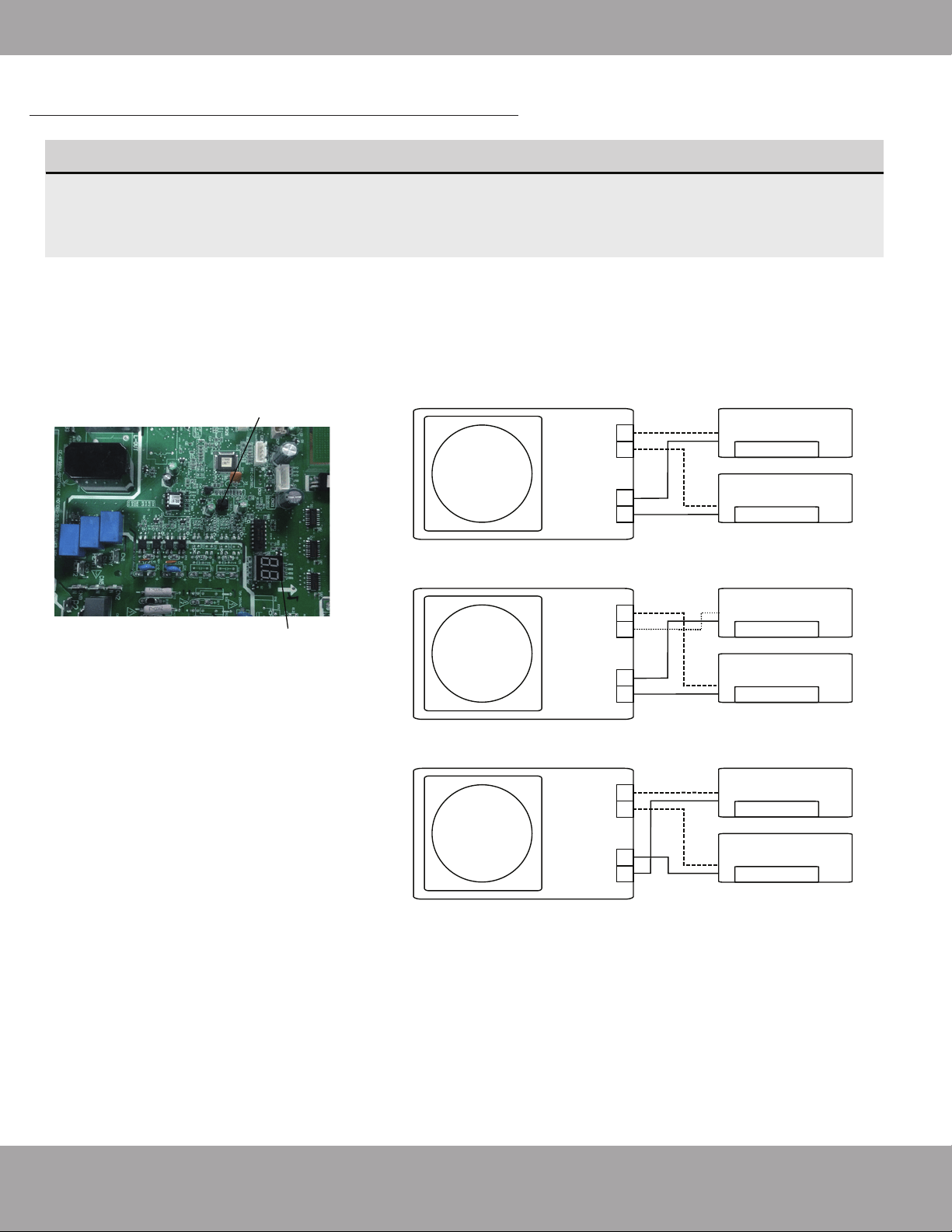
Page 42
Troubleshooting
mrcool.com
More recent models now feature automatic correction of wiring/piping errors. Press the "check
switch" on the outdoor unit PCB board for 5 seconds until the LED displays "CE”, indicatomg that
this function is working, Approximately 5-10 minutes after the switch is pressed, the "CE" disappears,
meaning that the wiring/piping error is corrected and all wiring/piping is properly connected.
How To Activate This Function
1.
Check that outside temperature is
above 5℃. (This function does not work
when outside temperature is not above 5
℃)
2. Check that the stop valves of the liquid
pipe and gas pipe are open.
3. Turn on the breaker and wait at least 2
minutes.
4. Press the check switch on the outdoor
PCB board unit LED display "C E".
Correct
Terminal
block
Liquid/
Gas pipe
Outdoor unit
Indoor unit B
Indoor unit A
B
A
B
A
Incorrect wiring
Terminal
block
Liquid/
Gas pipe
Outdoor unit
Indoor unit B
Indoor unit A
B
A
B
A
Incorrect wiring
Terminal
block
Liquid/
Gas pipe
Outdoor unit
Indoor unit B
Indoor unit A
B
A
B
A
Check switch
LED display
Automatic Wiring/Piping Correction Function
NOTE
The function for the automatic wiring/piping correction illustrated below is intended for use by
a licensed electrical technician only.
Page 43
mrcool.com
Refrigerant Piping Connection
Special notice
This appliance contains refrigerant and other potentially hazardous materials. When disposing of this appli-
ance, the law requires special collection and treatment. DO NOT dispose of this product as household waste
or unsorted municipal waste.
When disposing of this appliance, you have the following options:
• Dispose of the appliance at a designated municipal electronic waste collection facility.
• When buying a new appliance, the retailer will receive the old appliance free of charge.
• The manufacturer will receive the old appliance free of charge.
• Sell the appliance to certified scrap metal dealers.
Disposing of this appliance in the forest or other natural surroundings endangers your health
and is bad for the environment. Hazardous substances may leak into the ground water and
enter the food chain.
12
EU Disposal Guidelines

DIY
®
Multi-Zone
The design and specifications of this product and/or manual are subject to change without prior notice.
Consult with the sales agency or manufacturer for details.