
Split Air Conditioner
Thank you for choosing our product.
For proper operation, please read and keep this manual carefully.
If you have lost the Owner’s Manual, please contact the local agent or visit
www.impecca.com for an electronic version.
Models:
ISMI-W092
ISMI-W122
v. 1.1

R410A(R32/125: 50/50): 1975
Operation Notices
Precautions............................................................................................................1
Parts name ............................................................................................................6
Screen Operation Guide
Buttons on remote controller .................................................................................7
Introduction for icons on display screen ................................................................7
Introduction for buttons on remote controller .........................................................8
Function introduction for combination buttons.....................................................12
Operation guide...................................................................................................13
Replacement of batteries in remote controller.....................................................13
Emergency operation .......................................................................................... 14
Maintenance
Clean and maintenance....................................................................................... 14
Malfunction
Malfunction analysis ............................................................................................17
Installation Notice
Installation dimension diagram............................................................................21
Tools for installation .............................................................................................22
Selection of installation location ..........................................................................22
Requirements for electric connection ..................................................................23
Installation
Installation of indoor unit......................................................................................24
.29
Check after installation
...........................
.
............................................................
29
Test and operation
Test operation
......................................... ............................................................
Attachment
.........................................................................30
Pipe expanding method
Configuration of connection pipe
.......................................................................................32
Content
Wired Controller...................................................................................................
33
This appliance is not intended for use by persons (including children) with reduced physical, sensory
or mental capabilities, or lack of experience and knowledge, unless they have been given supervision
or instruction concerning use of the appliance by a person responsible for their safety.
Children should be supervised to ensure that they do not play with the appliance.
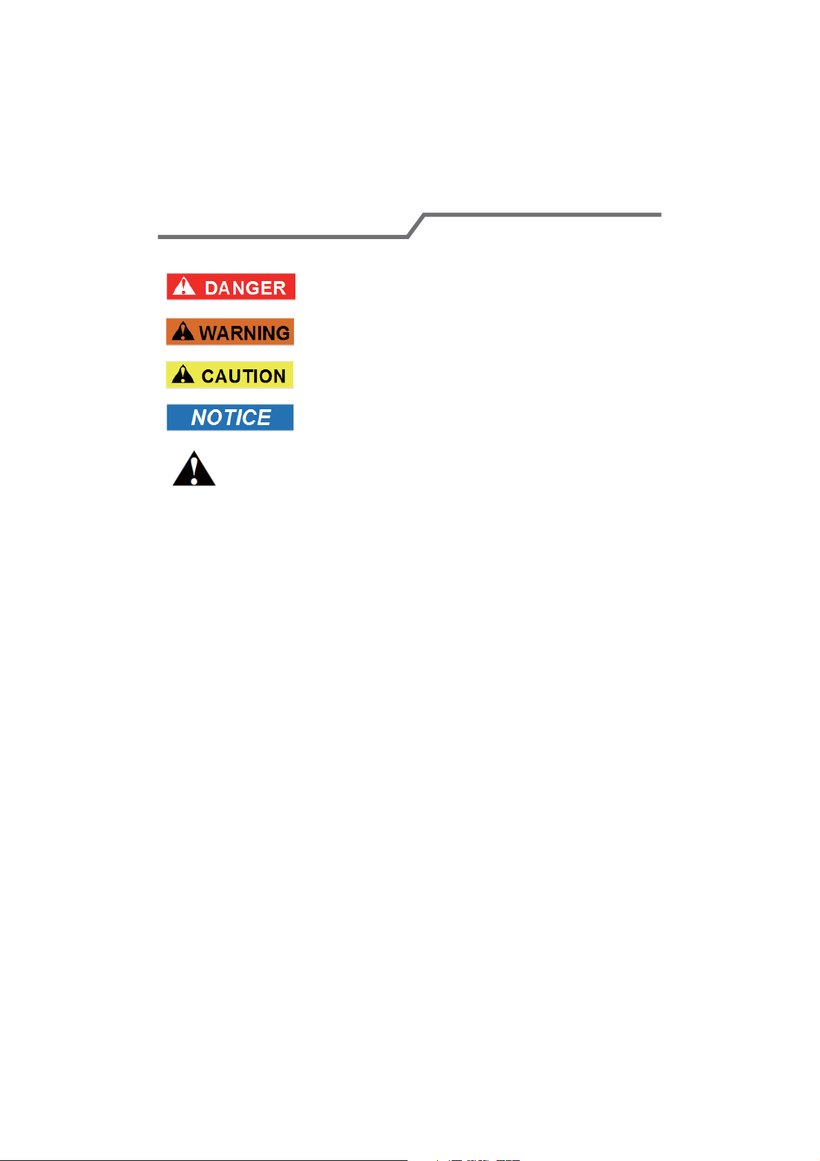
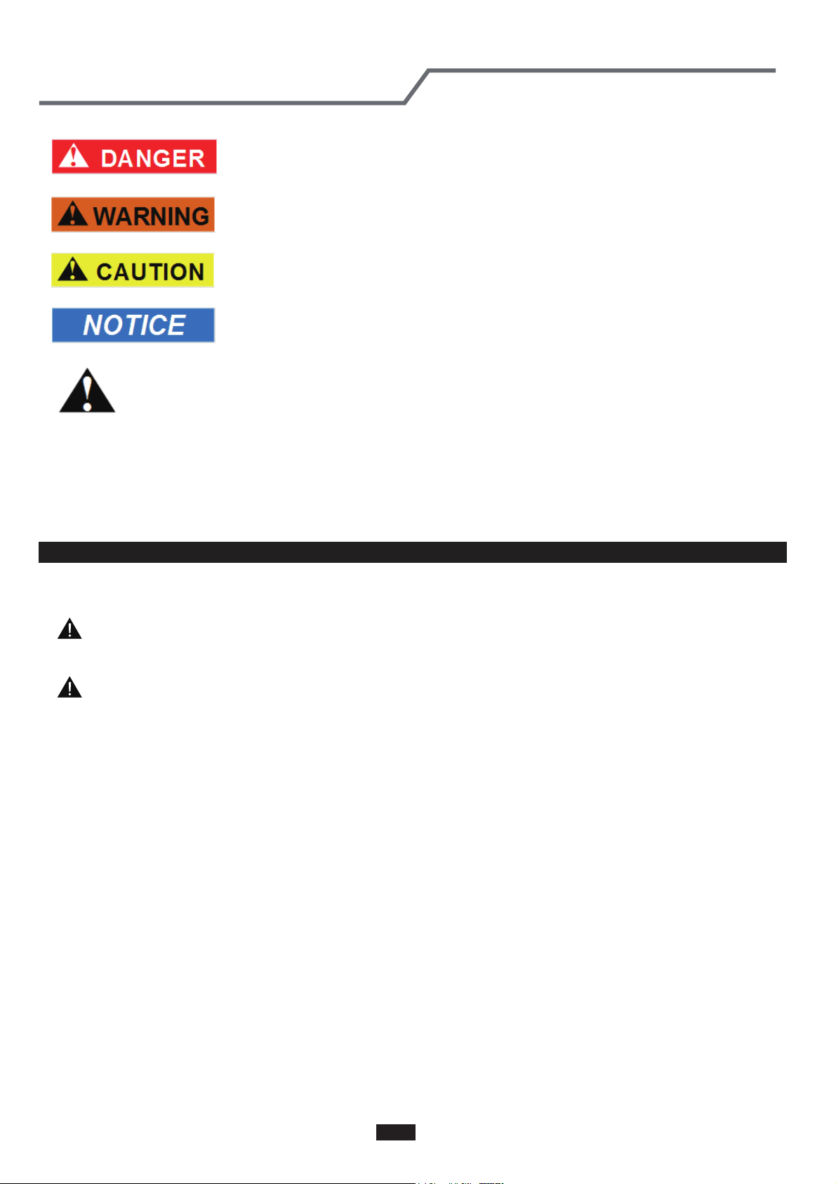
Explanation of Symbols
Indicates a hazardous situation that, if not avoided, will
result in death or serious injury.
Indicates a hazardous situation that, if not avoided, could
result in death or serious injury.
Indicates a hazardous situation that, if not avoided, may
result in minor or moderate injury.
Indicates important but not hazard-related information,
used to indicate risk of property damage.
Indicates a hazard that would be assigned a signal word
WARNING or CAUTION.
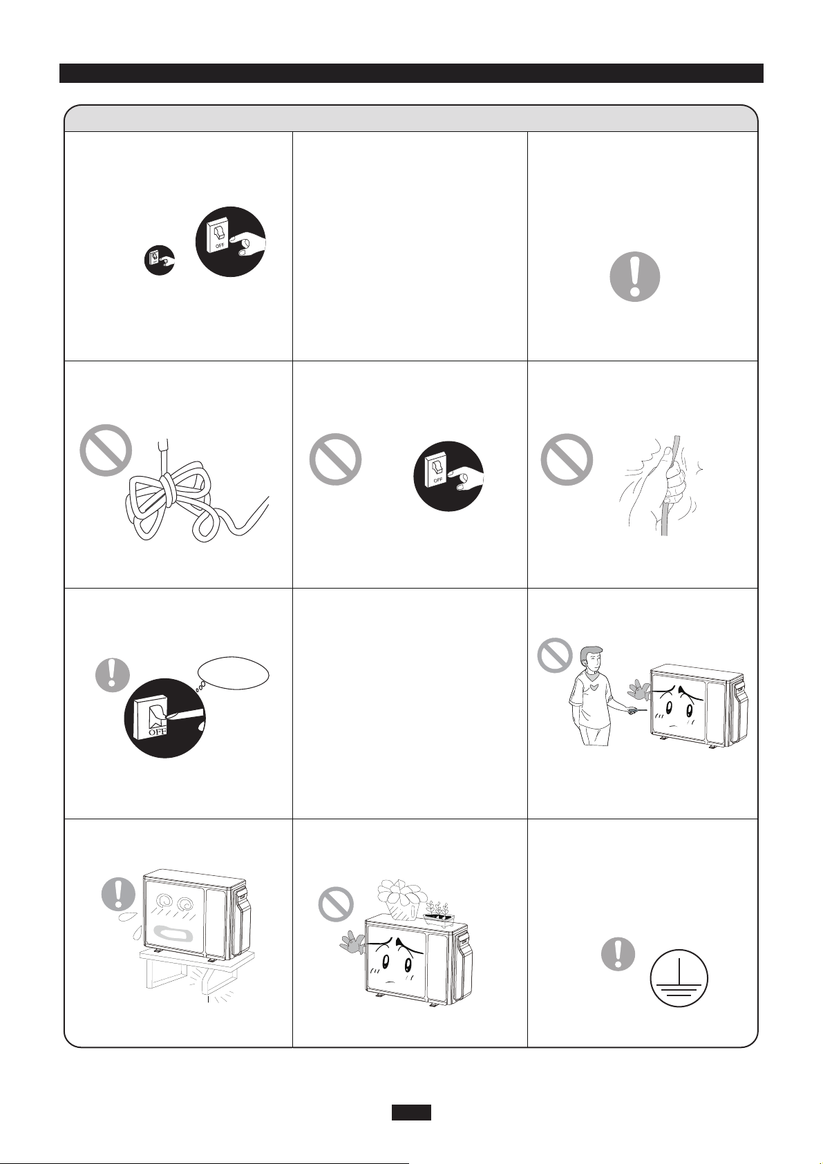
Precautions
WARNING
Do not connect air conditioner to multi-purpose socket.
This appliance can be used by children aged from 8
Operation and Maintenance
If the supply cord is damaged, it must be replaced by
the manufacturer, its service agent or similarly qualified
persons in order to avoid a hazard.
Do not spray water on indoor unit. It may cause electric
shock or malfunction.
Otherwise, it may cause fire hazard.
Children shall not play with the appliance.
Cleaning and user maintenance shall not be made by
children without supervision.
years and above and persons with reduced physical,
sensory or mental capabilities or lack of experience
and knowledge if they have been given supervision or
instruction concerning use of the appliance in a safe
way and understand the hazards involved.
Do not wash the air conditioner with water to avoid
electric shock.
After removing the filter, do not touch fins to avoid injury.
Do not use fire or hair dryer to dry the filter to avoid
deformation or fire hazard.
Do disconnect power supply when cleaning air
conditioner. Otherwise, it may cause electric shock.
.
1
Do not block air outlet or air inlet. It may cause
malfunction.
remote controller may be broken.
Ɣ Power cord is overheating or damaged.
Ɣ There’s abnormal sound during operation.
Ɣ Circuit break trips off frequently.
Ɣ Air conditioner gives off burning smell.
Ɣ Indoor unit is leaking.
contact the dealer or qualified professionals for service.
When turning on or turning off the unit by emergency
operation switch, please press this switch with an insulating
object other than metal.
outlet. It may cause personal injury or damage.
Precautions
WARNING
conditioner and disconnect power immediately, and then
If the air conditioner operates under abnormal conditions,
it may cause malfunction, electric shock or fire hazard.
Do not spill water on the remote controller, otherwise the
electric shock or damage. Please contact dealer when
you need to repair air conditioner.
Do not repair air conditioner by yourself. It may cause
objects. It may cause damage or personal injury.
Do not step on top panel of outdoor unit, or put heavy
When below phenomenon occurs, please turn off air
Do not extend fingers or objects into air inlet or air
Maintenance must be performed by qualified
professionals. Otherwise, it may cause personal injury
or damage.
2
Do install the circuit break. If not, it may cause malfunction.
of at least 3mm in all poles should be connected in fixed
wiring.
magnet buckle
and heating buckle function, it can protect
the circuit-short and
overload.
power supply circuit and circuit break.
Precautions
WARNING
note
the following table.Air switch should be included
Make sure the power supply matches with the
requirement of air conditioner.Unstable power supply or
incorrect wiring or malfunction. Please install proper power
supply cables before using the air conditioner.
An all-pole disconnection switch having a contact separation
Must follow the electric safety regulations when installing
the unit.
grounding wire of power socket.
Properly connect the live wire, neutral wire and
any work related to electricity and safety.
Be sure to cut off the power supply before proceeding
Including an circuit break with suitable capacity, please
Air Conditioner should be properly grounded. Incorrect
Don't use unqualified power cord.
grounding may cause electric shock.
According to the local safety regulations, use qualified
Installation must be performed by qualified professionals.
Otherwise, it may cause personal injury or damage.
Attachment
3
Installation must be performed in accordance with the
persons in order to avoid a hazard.
must be properly grounding with specialized grounding
device by a professional. Please make sure it is always
grounded effectively, otherwise it may cause electric shock.
The appliance must be positioned so that the plug is
accessible.
If the length of power connection wire is insufficient, please
contact the supplier for a new one. Avoid extending the
wire by yourself.
All wires of indoor unit and outdoor unit should be
connected by a professional.
national wiring regulations.
requirement of NEC and CEC by authorized personnel
only.
Precautions
WARNING
wire, which can't be used for other purposes.
The grounding resistance should comply with national
electric safety regulations.
The air conditioner is the first class electric appliance. It
keep the interconnection cable away from the copper
tube.
The temperature of refrigerant circuit will be high, please
the manufacturer, its service agent or similarly qualified
If the supply cord is damaged, it must be replaced by
The yellow-green wire in air conditioner is grounding
The appliance shall be installed in accordance with
Do not put through the power before finishing installation.
4
The indoor unit should be installed close to the wall.
reachable after finishing installation.
far away from animals or plants.If it is unavoidable,
please add the fence for safety purpose.
Precautions
WARNING
place, only the qualified person can perform the work.
Otherwise, it may cause personal injury or damage.
If you need to relocate the air conditioner to another
must be installed in the line.
For the air conditioner without plug, an circuit break
Select a location which is out of reach for children and
For the air conditioner with plug, the plug should be
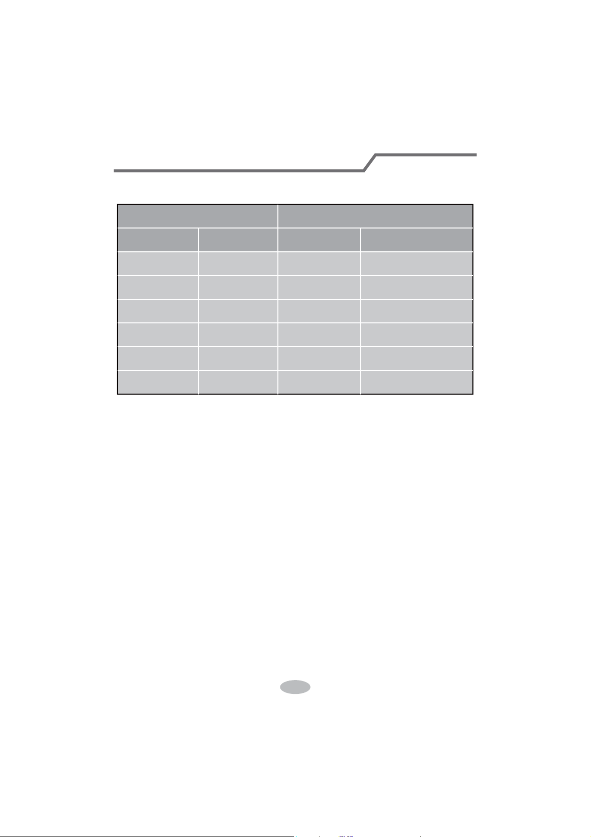
Working temperature range
NOTICE:
5
Indoor side DB/WB(
ć
) Outdoor side DB/WB(
ć
)
Maximum cooling 26.7/19.4 46.1/23.9
Maximum heating 26.7/- 23.9/18.3
Ɣ The temperature range for operating the unit with electric heating: -20℃~46.1℃;
the temperature range for operating the unit without electric heating: -18℃~46.1℃
6
(Display content or position may be different from above
graphics, please refer to actual products)
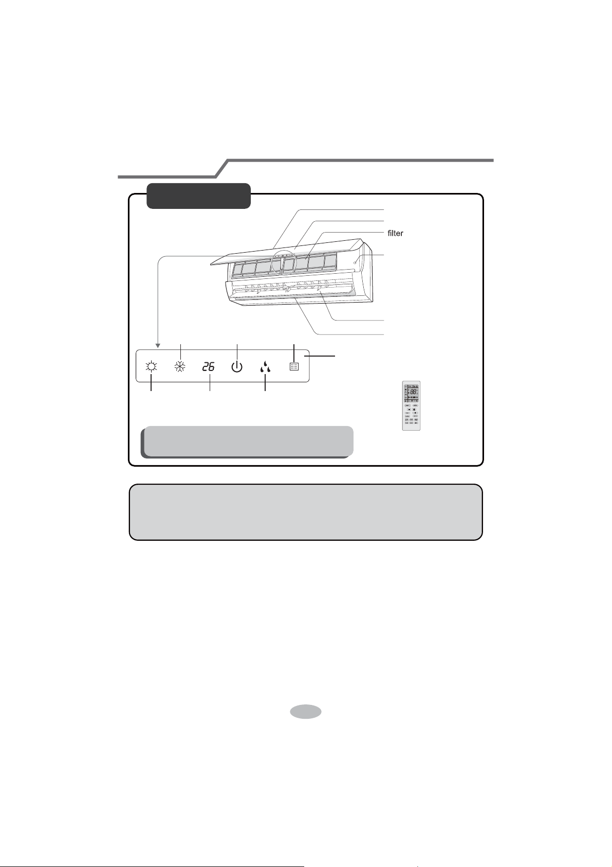
Parts Name
Indoor Unit
air inlet
panel
aux.button
horizontal louver
air outlet
heating
indicator
temp.
indicator
cooling
indicator
power
indicator
receiver
window
drying
indicator
display
remote controller
NOTICE:
Actual product may be different from above graphics, please refer to actual
products.
7
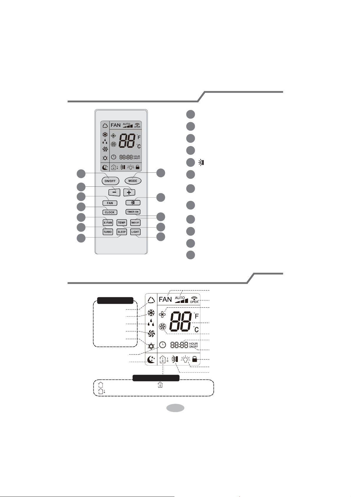
Buttons on remote controller
Introduction for icons on display screen
1
2
5
7
9
11
10
12
8
6
4
3
1
2
3
4
5
6
7
8
9
10
11
12
ON/OFF button
MODE button
+/- button
F
AN button
button
X-FAN button
Note: X-FAN is the same with BLOW
TEMP button
TURBO button
LIGHT button
SLEEP button
TIMER ON/TIMER OFF
button
CLOCK button
Send signal
Turbo mode
Set temperature
Set time
TIMER ON / TIMER OFF
Child lock
Up & down swing
Set fan speed
X-fan mode
Light
Temp. display type
:Set temp.
:Outdoor ambient temp.
:Indoor ambient temp.
Sleep
mode
Clock
Heat mode
Fan mode
Dry mode
Cool mode
Auto mode
Operation mode
8
Ɣ:KHQVHOHFWLQJDXWRPRGHDLUFRQGLWLRQHUZLOOVWDUWDXWRRSHUDWLRQDFFRUGLQJWR
LQGRRUDPELHQWWHPSHUDWXUH6HWWHPSHUDWXUHFDQ¶WEHDGMXVWHGDQGZLOOQRW
EHGLVSOD\HGDVZHOO3UHVV F$1EXWWRQFDQDGMXVWIDQVSHHG
3UHVVEXWWRQFDQDGMXVWIDQEORZLQJDQJOH
Ɣ$IWHUVHOHFWLQJFRROPRGHDLUFRQGLWLRQHUZLOORSHUDWHXQGHUFRROPRGH&RRO
LQGLFDWRU RQLQGRRUXQLWLV213UHVVRUEXWWRQWRDGMXVWVHWWHPSH
UDWXUH3UHVVF$1EXWWRQWRDGMXVWIDQVSHHG3UHVVEXWWRQWRDGMXVWIDQ
EORZLQJDQJOH
Ɣ:KHQVHOHFWLQJGU\PRGHWKHDLUFRQGLWLRQHURSHUDWHVDWORZVSHHGXQGHUGU\
PRGH'U\LQGLFDWRURQLQGRRUXQLWLV218QGHUGU\PRGHIDQVSHHGFDQ¶W
EHDGMXVWHG3UHVVEXWWRQWRDGMXVWIDQEORZLQJDQJOH
Ɣ:KHQVHOHFWLQJIDQPRGHWKHDLUFRQGLWLRQHUZLOORQO\EORZIDQQRFRROLQJDQG
QRKHDWLQJ$OOLQGLFDWRUVDUH2)F3UHVVF$1EXWWRQWRDGMXVWIDQVSHHG3UHVV
EXWWRQWRDGMXVWIDQEORZLQJDQJOH
Ɣ:KHQVHOHFWLQJKHDWLQJPRGHWKHDLUFRQGLWLRQHURSHUDWHVXQGHUKHDWPRGH
+HDWLQGLFDWRURQLQGRRUXQLWLV213UHVVRUEXWWRQWRDGMXVWVHW
WHPSHUDWXUH3UHVVFANEXWWRQWRDGMXVWIDQVSHHG3UHVVEXWWRQWRDGMXVW
IDQEORZLQJDQJOH&RROLQJRQO\XQLWZRQ¶WUHFHLYHKHDWLQJPRGHVLJQDO,IVHWWLQJ
KHDWPRGHZLWKUHPRWHFRQWUROOHUSUHVV212))EXWWRQFDQ¶WVWDUWXSWKHXQLW
Note:
Ɣ)RUSUHYHQWLQJFROGDLUDIWHUVWDUWLQJXSKHDWLQJPRGHLQGRRUXQLWZLOOGHOD\a
PLQXWHVWREORZDLUDFWXDOGHOD\WLPHLVGHSHQGRQLQGRRUDPELHQWWHPSHUDWXUH
Ɣ6HWWHPSHUDWXUHUDQJHIURPUHPRWHFRQWUROOHUa
ć
)DQVSHHGDXWRORZ
VSHHGPHGLXPVSHHGKLJKVSHHG
Introduction for buttons on remote controller
Note:
Ɣ$IWHUSXWWLQJWKURXJKWKHSRZHUWKHDLUFRQGLWLRQHUZLOOJLYHRXWDVRXQG
2SHUDWLRQLQGLFWRULV21UHGLQGLFDWRU$IWHUWKDW\RXFDQRSHUDWHWKHDLU
FRQGLWLRQHUE\XVLQJUHPRWHFRQWUROOHU
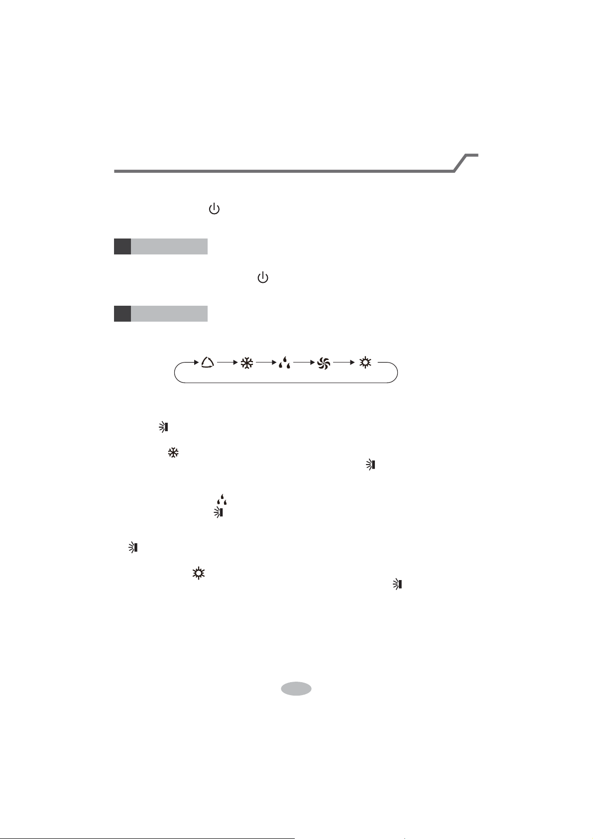
212))EXWWRQ
02'(EXWWRQ
1
2
3UHVVWKLVEXWWRQFDQWXUQRQRUWXUQRIIWKHDLUFRQGLWLRQHU$IWHUWXUQLQJRQWKHDLU
FRQGLWLRQHURSHUDWLRQLQGLFDWRU RQLQGRRUXQLW¶VGLVSOD\LV21JUHHQLQGLFDWRU
7KHFRORXULVGLIIHUHQWIRUGLIIHUHQWPRGHOVDQGLQGRRUXQLWZLOOJLYHRXWDVRXQG
3UHVVWKLVEXWWRQWRVHOHFW\RXUUHTXLUHGRSHUDWLRQPRGH
$8T2 &22/ FAN'RY +(AT
9
Introduction for buttons on remote controller
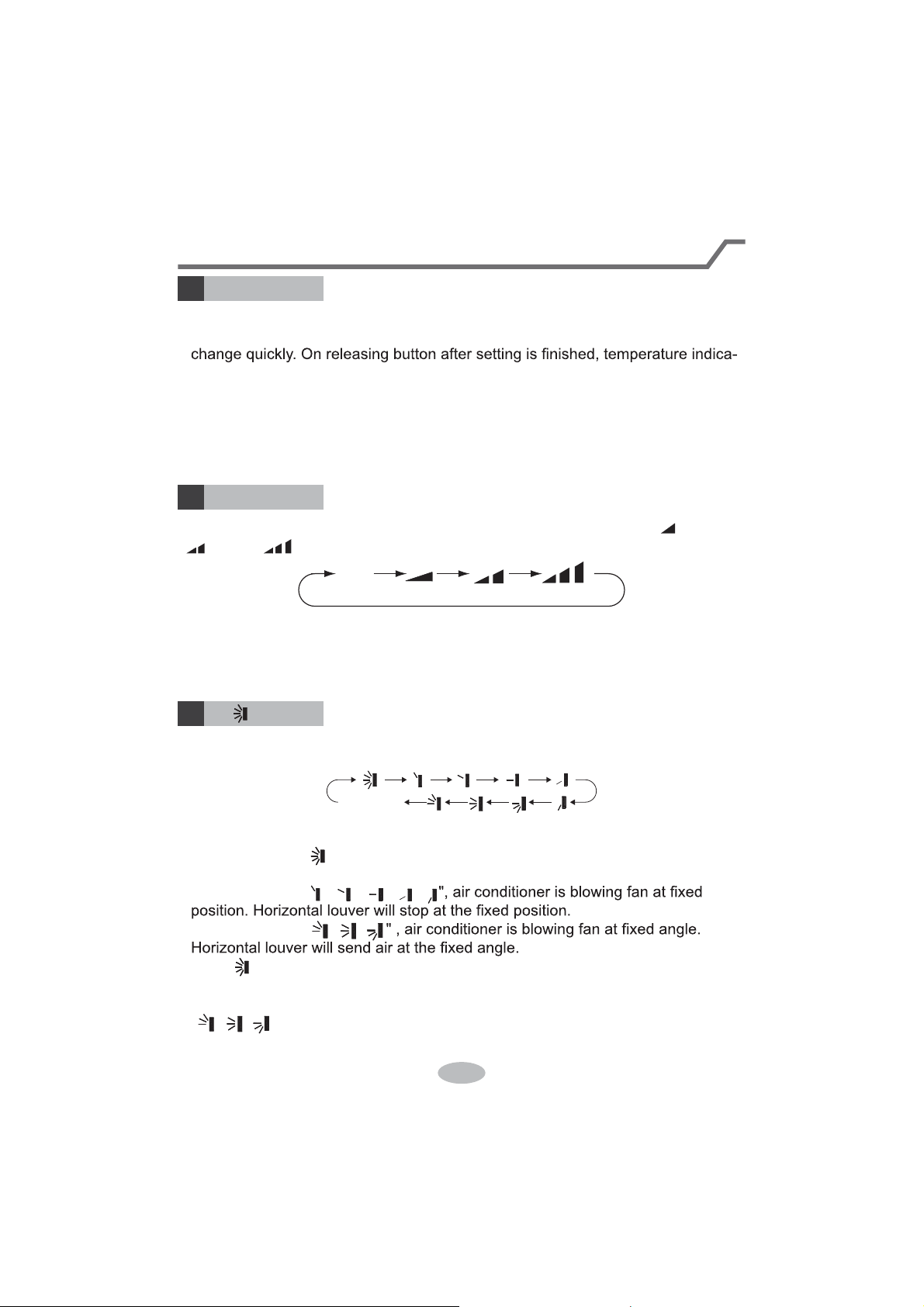
FAN button
4
Pressing this button can set fan speed circularly as: auto (AUTO), low( ), medium
( ), high( ).
Auto
Note:
Ɣ8QGHU AUTO speed,
Ɣ)DQVSHHGXQGHUGU\PRGHLVORZVSHHG
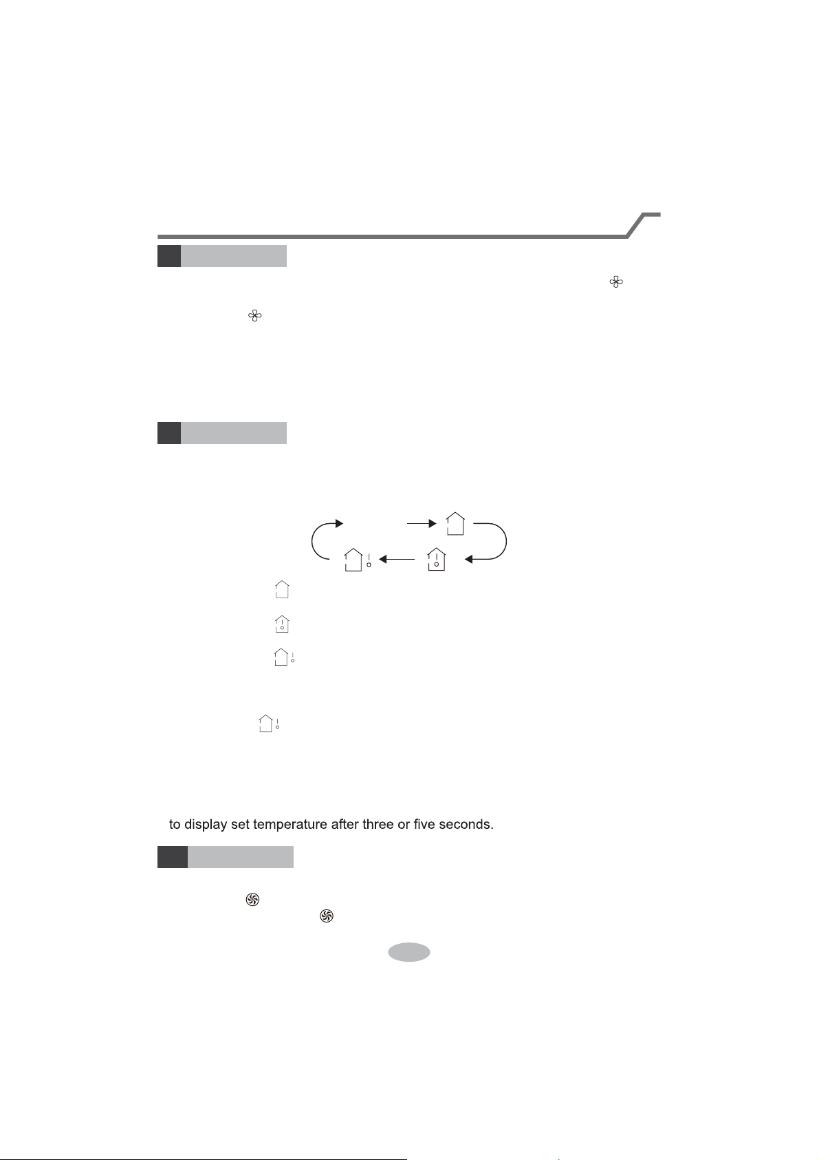
5
Press this button can select up&down swing angle. Fan blow angle can be selected
circularly as below:
Ɣ:KHQVHOHFWLQJDLUFRQGLWLRQHULVEORZLQJIDQDXWRPDWLFDOO\. Horizontal
louver will automatically swing up & down at maximum angle.
Ɣ:KHQVHOHFWLQJ
ǃǃǃǃ
Ɣ:KHQVHOHFWLQJ
ǃǃ
Ɣ+ROG EXWWRQDERYHVWRVHW\RXUUHTXLUHGVZLQJDQJOH:KHQUHDFKLQJ\RXU
required angle, release the button.
Note:
Ɣ
ǃǃ
PD\QRWEHDYDLODEOH:KHQDLUFRQGLWLRQHUUHFHLYHVWKLVsignal, the
air conditioner will blow fan automatically.
button
no display
(horizontal louvers stops
at current position)
+/- button
3
Ɣ3UHVVRUEXWWRQRQFHLQFUHDVHRUGHFUHDVHVHWWHPSHUDWXUH
ć
.
+ROGLQJRUEXWWRQVODWHr, set temperature on remote controller will
tor on indoor unit will change accordingly. (Temperature can’t be adjusted under
auto mode)
Ɣ:KHQVHWWLQJ TIMER ON, TIMER OFF oU&/2&.SUHVVRUEXWWRQWR
adjust time. (Refer to CLOCK, TIMER ON, 7,0(52))EXWWRQV:KHQVHWWLQJ
TIMER ON, TIMER OFF or CLOCK, preVVRUEXWWRQWRDGMXVWWLPH5HIHU
to CLOCK, TIMER ON, TIMER OFF buttons)
the IDU fan motor will adjust the fan speed (high, medium or
low speed) according to ambient temperature.
10
Press this button to set clock time. " " icon on remote controller will blink. Press
"+" or "-" button within 5s to set clock time. Each pressing of "+" or "-" button, clock
time will increase or decrease 1 minute. If hold "+" or "-" button, 2s later, time will
change quickly. Release this button when reaching your required time. Press
Note:
Ɣ&ORFNWLPHDGRSWVKRXUPRGH
Ɣ The interval between two operation can’t exceeds 5s. Otherwise, remote contro-
ller will quit setting status. Operation for TIMER ON/TIMER OFF is the same.
&/O&K button
6
Introduction for buttons on remote controller
TIMER ON / TIMER OFF button
7
Ɣ TIMER ON button
"TIMER ON" button can set the time for timer on. After pressing this button, " "
icon disappears and the word "ON" on remote controller blinks. Press "+" or "-"
button to adjust TIMER ON setting. After each pressing "+" or "-" button, TIMER
ON setting will increase or decrease 1min. Hold "+" or "-" button, 2s later, the
time will change quickly until reaching your required time.
UHVXPHVGLVSOD\LQJ&DQFHO TIMER ON: Under the condition that TIMER ON is
started up, press "TIMER ON" button to cancel it.
Ɣ TIMER OFF button
"TIMER OFF" button can set the time for timer off. After pressing this button," "
icon disappears and the word "OFF" on remote controller blinks. Press "+" or "-"
button to adjust TIMER OFF setting. After each pressing "+" or "-" button, TIMER
OFF setting will increase or decrease 1min. Hold "+" or "-" button, 2s later, the
time will change quickly until reaching your required time.
Press "TIMER OFF" word "OFF" will stop blinking. " " icon resumes displaying.
&DQFHO TIMER OFF. Under the condition that TIMER OFF is started up, press
"TIMER OFF" button to cancel it.
Note:
Ɣ8QGHURQDQGRff status, you can set TIMER OFF or TIMER ON simultaneously.
Ɣ%HIRUHVHWWLQJ TIMER ON or TIMER OFF, please adjust the clock time.
Ɣ After starting up TIMER ON or TIMER OFF, set the constant circulating valid.
After that, air conditioner will be turned on or turned off according to setting time.
ON/OFF button has no effect on setting. If you don’t need this function, please
use remote controller to cancel it.
11
TEMP button
9
Introduction for buttons on remote controller
By pressing this button, you can see indoor set temperature, indoor ambient temp-
erature or outdoor ambient temperature on indoor unit’s display. The setting on
remote controlleris selected circularly as below:
no display
Ɣ:KHQVHOHFWLQJRUQRGLVSOD\ZLWKUHPRWHFRQWUROOHr, temperature indicator
on indoor unit displays set temperature.
Ɣ:KHQVHOHFWLQJZLWKUHPRWHFRQWUROOHr, temperature indicator on indoor unit
displays indoor ambient temperature.
Ɣ:KHQVHOHFWLQJZLWKUHPRWHFRQWUROOHr, temperature indicator on indoor unit
displays outdoor ambient temperature.
Note:
Ɣ
Outdoor temperature display is not available for some models. At that time, indoor
XQLWUHFHLYHV signal, while it displays indoor set temperature.
Ɣ,W’s defaulted to display set temperature when turning on the unit.There is no
display in the remote controller.
Ɣ2QO\IRUWKHPRGHOVZKRVHLQGRRUXQLWKDVGXDOGLVSODy.
Ɣ:KHQVHOHFWLQJGLVSOD\LQJRILQGRRURURXWGRRUDPELHQWWHPSHUDWXUHLQGRRU
temperature indicator displays corresponding temperature and automatically turn
X-FAN button
8
3UHVVWKLVEXWWRQXQGHUFRRODQGGU\PRGHWRVWDUWXS[IDQIXQFWLRQDQGLFRQ
on remote controller will be displayed. Press this button again to cancel x-fan
IXQFWLRQDQG LFRQZLOOGLVDSSHDr.
Note:
Ɣ:KHQ[IDQIXQFWLRQLVRQLIWKHDLUFRQGLWLRQHULVWXUQHGRIf, indoor fan will still
operate at low speed for a while to blow the residual water inside the air duct.
Ɣ'XULQJ[IDQRSHUDWLRQSUHVV;FAN button to turn ofI[IDQIXQFWLRQ,QGRRUIDQ
will stop operation immediately.
TURBO button
10
Under COOL or HEAT mode, press this button to turn to quick COOL or quick
HEATPRGHLFRQLVGLVSOD\HGRQUHPRWHFRQWUROOHr. Press this button again
WRH[LWWXUERIXQFWLRQDQGLFRQZLOOGLVDSSHDr.
12
Function introduction for combination buttons
Child lock function
Press "+" and "-" simultaneously to turn on or turn off child lock function. When
child lock function is on, " " icon is displayed on remote controller. If you operate
the remote controller, the " " icon will blink three times without sending signal to
the unit.
Temperature display switchover function
Under OFF status, press "-" and "MODE" buttons simultaneously to switch temp-
erature display between
ć
and
.
Introduction for buttons on remote controller
Press this button to turn off display light on indoor unit. " " icon on remote
controller disappears. Press this button again to turn on display light. " " icon is
displayed.
Under COOL, HEAT or DRY mode, press this button to start up sleep function.
" " icon is displayed on remote controller. Press this button again to cancel sleep
function and " " icon will disappear.
SLEEP button
LIGHT button
11
12
13
1.
After putting through the power, press "ON/OFF" button on remote controller to
turn on the air conditioner.
2.
Press "MODE" button to select your required mode: AUTO, COOL, DRY, FAN,
HEAT.
3.
Press "+" or "-" button to set your required temperature. (Temperature can’t be
adjusted under auto mode).
4.
Press "FAN" button to set your required fan speed: auto, low, medium and high
speed.
5.
Press " " button to select fan blowing angle.
Operation guide
Replacement of batteries in remote controller
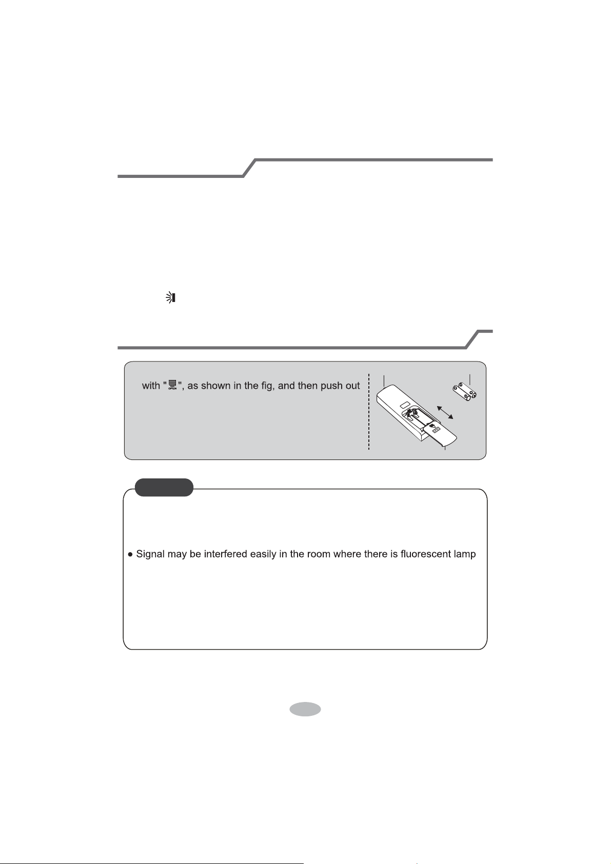
1. Press the back side of remote controller marked
the cover of battery box along the arrow direction.
2. Replace two 7# (AAA 1.5V) dry batteries, and
make sure the position of "+" polar and "-" polar
are correct.
3. Reinstall the cover of battery box.
signal sender battery
Cover of battery box
remove
reinstall
NOTICE
Ɣ'XULQJRSHUDWLRQSRLQWWKHUHPRWHFRntrol signal sender at the receiving
window on indoor unit.
Ɣ The distance between signal sender and receiving window should be no
more than 8m, and there should be no obstacles between them.
or wireless telephone; remote controller should be close to indoor unit during
operation.
Ɣ5HSODFHQHZEDWWHULHVRIWKHVDPHPRGHOZKHQUHSODFHPHQWLVUHTXLUHG
Ɣ:KHQ\RXGRQ¶WXVHUHPRWHFRQWUROOHUIRUDORQJWLPHSOHDVHWDNHRXWWKH
batteries.
Ɣ,IWKHGLVSOD\RQUHPRWHFRQWUROOHULVIX]]\RUWKHUH’s no display, please
replace batteries.
14
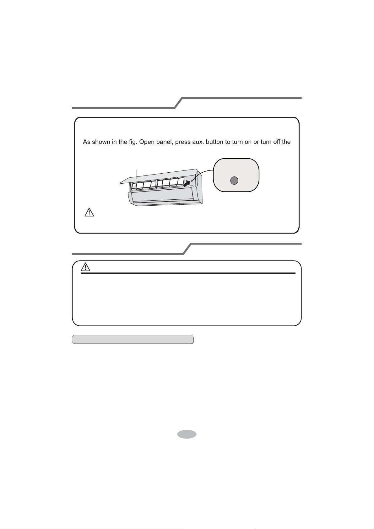
Emergency operation
Clean and maintenance
air conditioner. When the air conditioner is turned on, it will operate under
auto mode.
aux. button
panel
WARNING:
Use insulated object to press the auto button
If remote controller is lost or damaged, please use auxiliary button to turn
on or turn of
f the air conditioner. The operation in details are as below:
WARNING
NOTICE:
Ŷ Turn off the air conditioner and disconnect the power before cleaning the air
conditioner to avoid electric shock.
Ŷ'RQRWZDVKWKHDLUFRQGLWLRQHUZLWKZDWHUWRDYRLGHOHFWULFVKRFN
Ŷ'RQRWXVHYRODWLOHOLTXLGWRFOHDQWKHDLUFRQGLWLRQHr.
Clean surface of indoor unit
When the surface of indoor unit is dirty, it is recommended to use a soft dry cloth
or wet cloth to wipe it.
Ɣ'RQRWUHPRYHWKHSDQHOZKHQFOHDQLQJLW
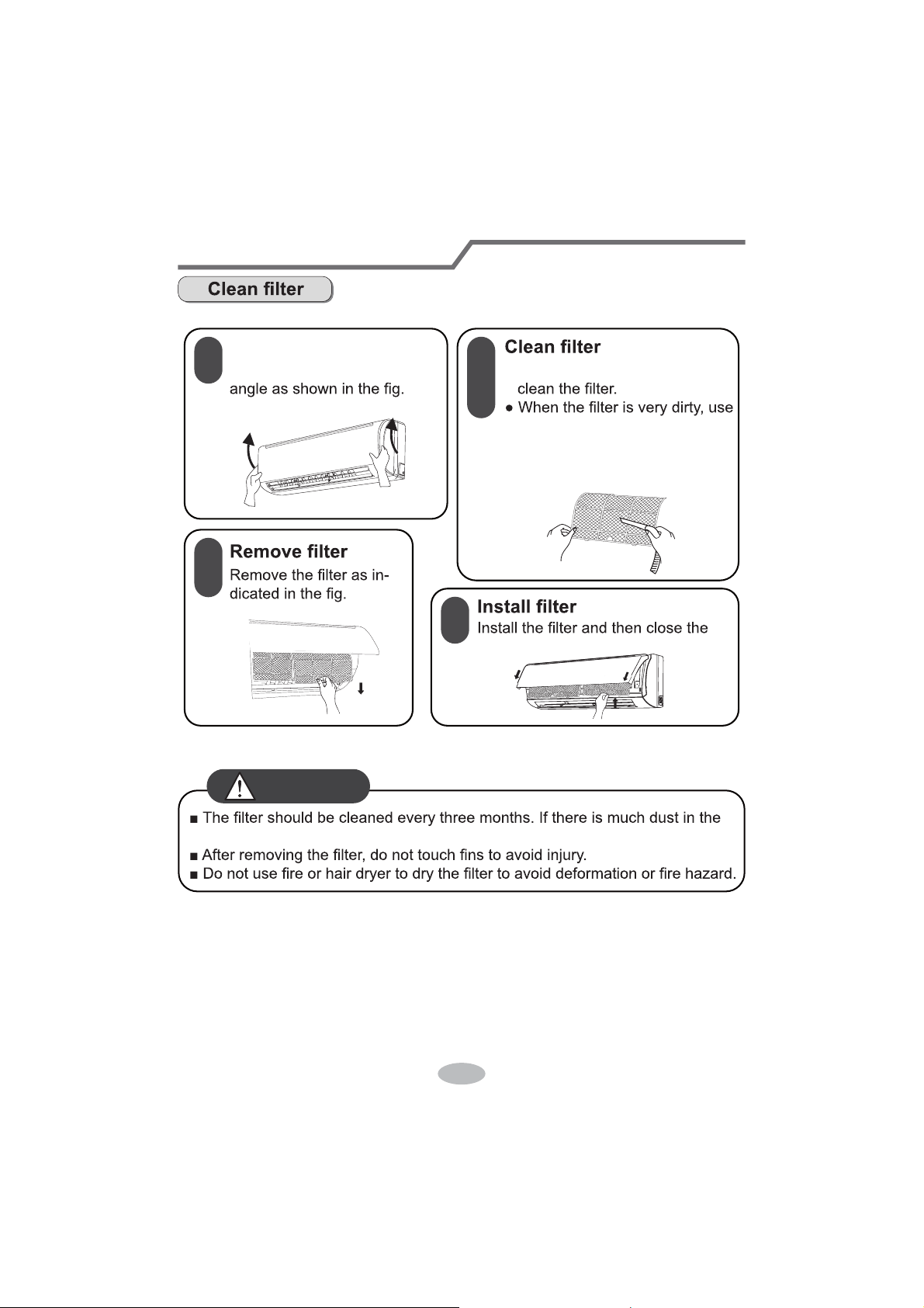
Clean and maintenance
1
2
3
4
Open panel
Pull out the panel to a certain Ɣ8VHGXVWFDWFKHURUZDWHUWR
WKHZDWHUEHORZ
ć
) to clean
LWDQGWKHQSXWLWLQDVKDG\
DQGFRROSODFHWRGU\.
panel cover tightl\.
RSHUDWLRQHQYLURQPHQWFOHDQIUHTXHQF\FDQEHLQFUHDVHG
WARNING
Clean and maintenance
Notice for recovery
1. Many packing materials are recyclable materials.
Please dispose them in appropriate recycling unit.
2. If you want to dispose the air conditioner, please contact local dealer or
consultant service center for the correct disposal method.
16
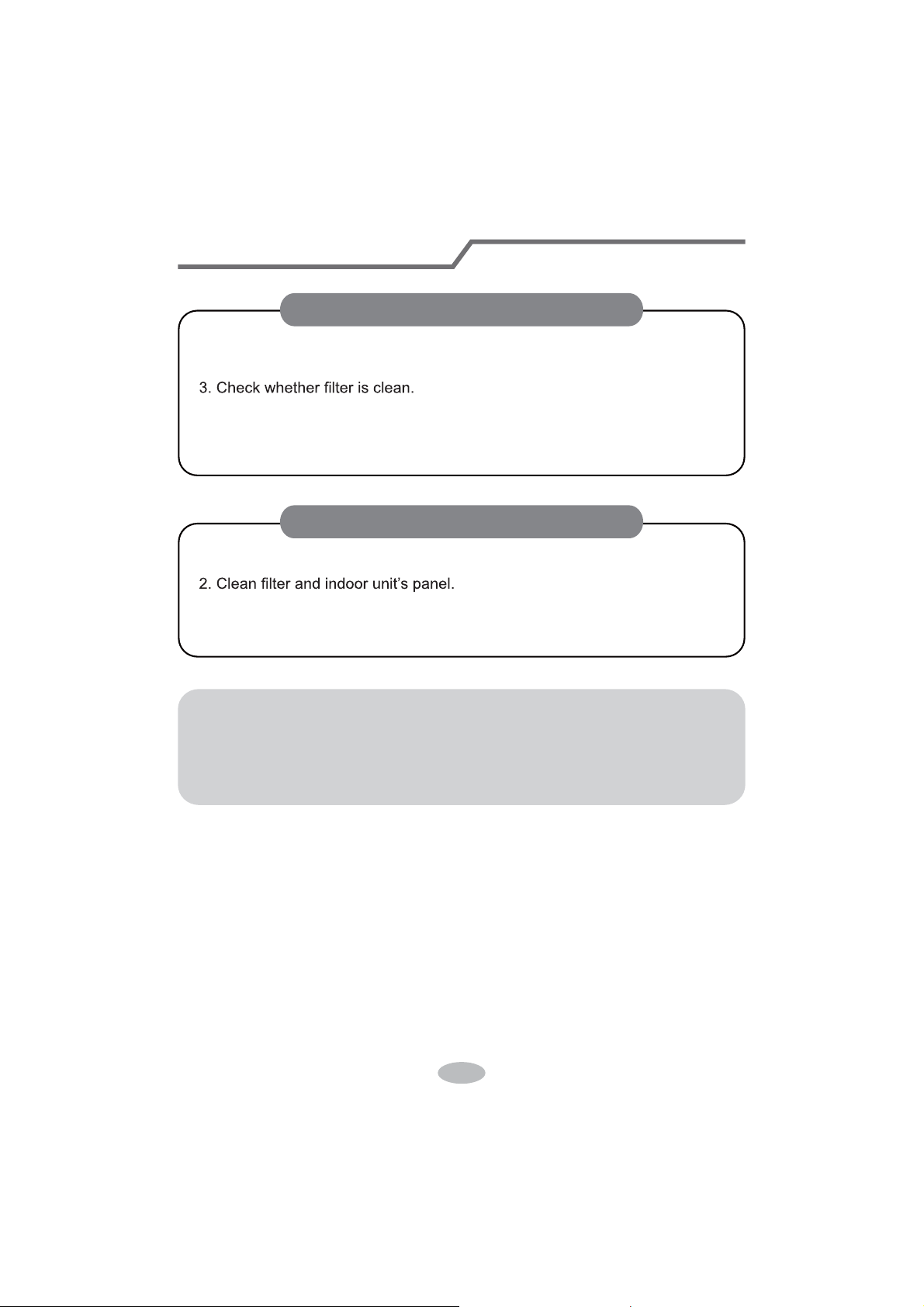
1. Check whether air inlets and air outlets are blocked.
2. Check whether air switch, plug and socket are in good condition.
4. Check whether mounting bracket for outdoor unit is damaged or corroded.
If yes, please contact dealer.
5. Check whether drainage pipe is damaged.
1. Disconnect power supply.
3. Check whether mounting bracket for outdoor unit is damaged or corroded.
If yes, please contact dealer.
NOTICE: Checking before use-season
NOTICE: Checking after use-season
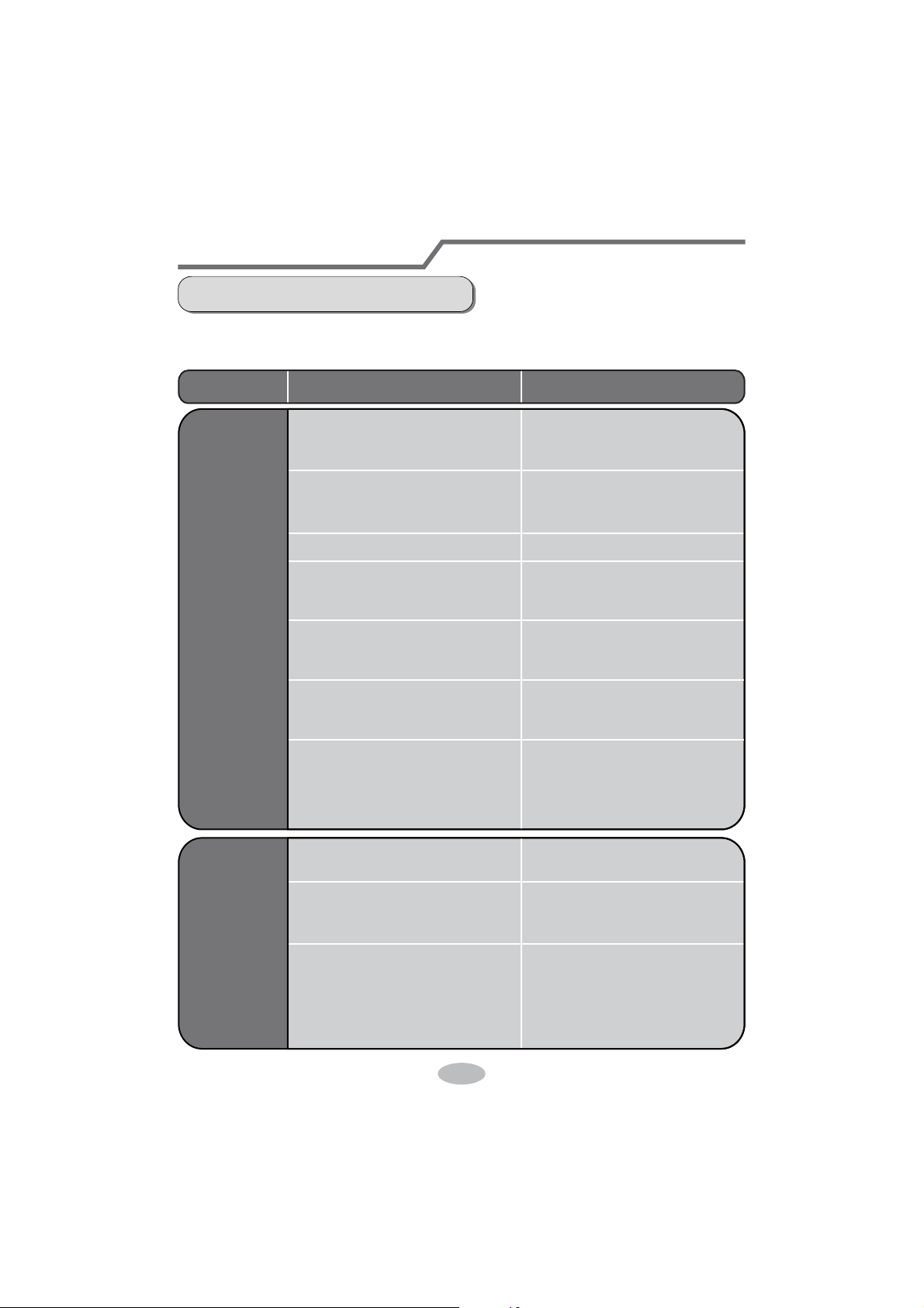
Malfunction analysis
General phenomenon analysis
Please check below items before asking for maintenance. If the malfunction still
FDQ¶WEHHOLPLQDWHGSOHDVHFRQWDFWORFDOGHDOHURUTXDOL¿HGSURIHVVLRQDOV
Phenomenon Check items Solution
Indoor unit
FDQ¶WUHFHLYH
remote
FRQWUROOHU¶V
signal or
remote
controller
has no
action.
Ɣ:KHWKHULWVLQWHUIHUHGVHYHUHO\
(such as static electricity
,stable
voltage)?
Ɣ:KHWKHUUHPRWHFRQWUROOHULV
within the signal receiving
range?
Ɣ:KHWKHUWKHUHDUHREVWDFOHV"
Ɣ:KHWKHUUHPRWHFRQWUROOHULV
pointing at the receiving
window?
Ɣ,VVHQVLWLYLW\RIUHPRWHFRQWUR
OOHUORZIX]]\GLVSOD\DQGQR
display?
Ɣ1RGLVSOD\ZKHQRSHUDWLQJ
remote controller?
Ɣ)OXRUHVFHQWODPSLQURRP"
Ɣ3XOORXWWKHSOXJ5HLQVHUW
the plug after about 3min, and
then turn on the unit again.
Ɣ6LJQDOUHFHLYLQJUDQJHLVP
Ɣ5HPRYHREVWDFOHV
Ɣ
Select proper angle and point
the remote controller at the re-
ceiving window on indoor unit.
Ɣ&KHFNWKHEDWWHULHV,IWKH
power of batteries is too low,
please replace them.
Ɣ7DNHWKHUHPRWHFRQWUROOHU
close to indoor unit.
Ɣ7XUQRIIWKHÀXRUHVHQWODPS
and then try it again.
Ɣ&KHFNZKHWKHUUHPRWHFRQW
roller appears to be damaged.
If yes, replace it.
No air
emitted
from
indoor
unit
Ɣ$LULQOHWRUDLURXWOHWRILQGRRU
unit is blocked?
Ɣ(OLPLQDWHREVWDFOHV
Ɣ8QGHUKHDWLQJPRGHLQGRRU
temperature is reached to set
temperature?
Ɣ
$IWHUUHDFKLQJWRVHWWHPSHU
ature, indoor unit will stop bl-
owing out air.
Ɣ+HDWLQJPRGHLVWXUQHGRQMXVW
now?
Ɣ,QRUGHUWRSUHYHQWEORZLQJ
out cold air, indoor unit will be
started after delaying for sev-
eral minutes, which is a nor-
mal phenomenon.
17

Malfunction analysis
Ɣ3RZHUIDLOXUH"
Ɣ,VSOXJORRVH"
Ɣ&LUFXLWEUHDNWULSVRIIRU
fuse is burnt out?
Ɣ:LULQJKDVPDOIXQFWLRQ"
Ɣ8QLWKDVUHVWDUWHGLPPHGLDWHO\
after stopping operation?
Ɣ:KHWKHUWKHIXQFWLRQVHWWLQJ
for remote controller is
correct?
Ɣ5HVHWWKHIXQFWLRQ
Ɣ:DLWIRUPLQDQGWKHQWXUQ
on the unit again.
Ɣ$VNSURIHVVLRQDOWRUHSODFHLW
Ɣ$VNSURIHVVLRQDOWRUHSODFH
circuit break or fuse.
Ɣ5HLQVHUWWKHSOXJ
Ɣ:DLWXQWLOSRZHUUHFRYHU\
Air condit-
LRQHUFDQ¶W
operate
Mist is em-
itted from
LQGRRUXQLW¶V
air outlet
Ɣ,QGRRUWHPSHUDWXUHDQGKXP
idity is high?
Ɣ%HFDXVHLQGRRUDLULVFRROHG
rapidly. After a while, indoor
temperature and humidity will
be decrease and mist will
disappear.
Phenomenon Check items Solution
Set temper-
DWXUHFDQ¶W
be adjusted
Ɣ8QLWLVRSHUDWLQJXQGHUDXWR
mode?
Ɣ
7HPSHUDWXUHFDQ¶WEHDGMX
sted under auto mode.
Please switch the operation
mode if you need to adjust
temperature.
Ɣ<RXUUHTXLUHGWHPSHUDWXUH
exceeds the set temperature
range?
Ɣ6HWWHPSHUDWXUHUDQJH
16
ć
~30
ć
.
Cooling
(heating)
effect is
not good.
Ɣ9ROWDJHLVWRRORZ"
Ɣ:DLWXQWLOWKHYROWDJH
resumes normal.
Ɣ)LOWHULVGLUW\" Ɣ&OHDQWKH¿OWHU
Ɣ6HWWHPSHUDWXUHLVLQSURSHU
range?
Ɣ$GMXVWWHPSHUDWXUHWRSURSHU
range.
Ɣ'RRUDQGZLQGRZDUHRSHQ" Ɣ&ORVHGRRUDQGZLQGRZ
18
Phenomenon Check items Solution
Odours are
emitted
Ɣ:KHWKHUWKHUH¶VRGRXUVRXUFH
such as furniture and cigarette,
etc.
Ɣ(OLPLQDWHWKHRGRXUVRXUFH
Ɣ&OHDQWKH¿OWHU
Air conditio-
ner operates
abnormally
Ɣ:KHWKHUWKHUH¶VLQWHUIHUHQFH
such as thunder, wireless
devices, etc.
Ɣ'LVFRQQHFWSRZHUSXWEDFN
power, and then turn on the
unit again.
Outdoor
unit has
vapor
Ɣ+HDWLQJPRGHLVWXUQHGRQ"
Ɣ'XULQJGHIURVWLQJXQGHUKH
ating mode, it may generate
vapor
, which is a normal
phenomenon.
“Water
ÀRZLQJ´
noise
Ɣ$LUFRQGLWLRQHULVWXUQHGRQRU
turned of
f just now?
Ɣ7KHQRLVHLVWKHVRXQGRI
UHIULJHUDQWÀRZLQJLQVLGH
the unit, which is a normal
phenomenon.
Cracking
noise
Ɣ$LUFRQGLWLRQHULVWXUQHGRQRU
turned of
f just now?
Ɣ7KLVLVWKHVRXQGRIIULFWLRQ
caused by expansion and/or
contraction of panel or other
parts due to the change of
temperature.
Malfunction analysis
19
20
Malfunction analysis
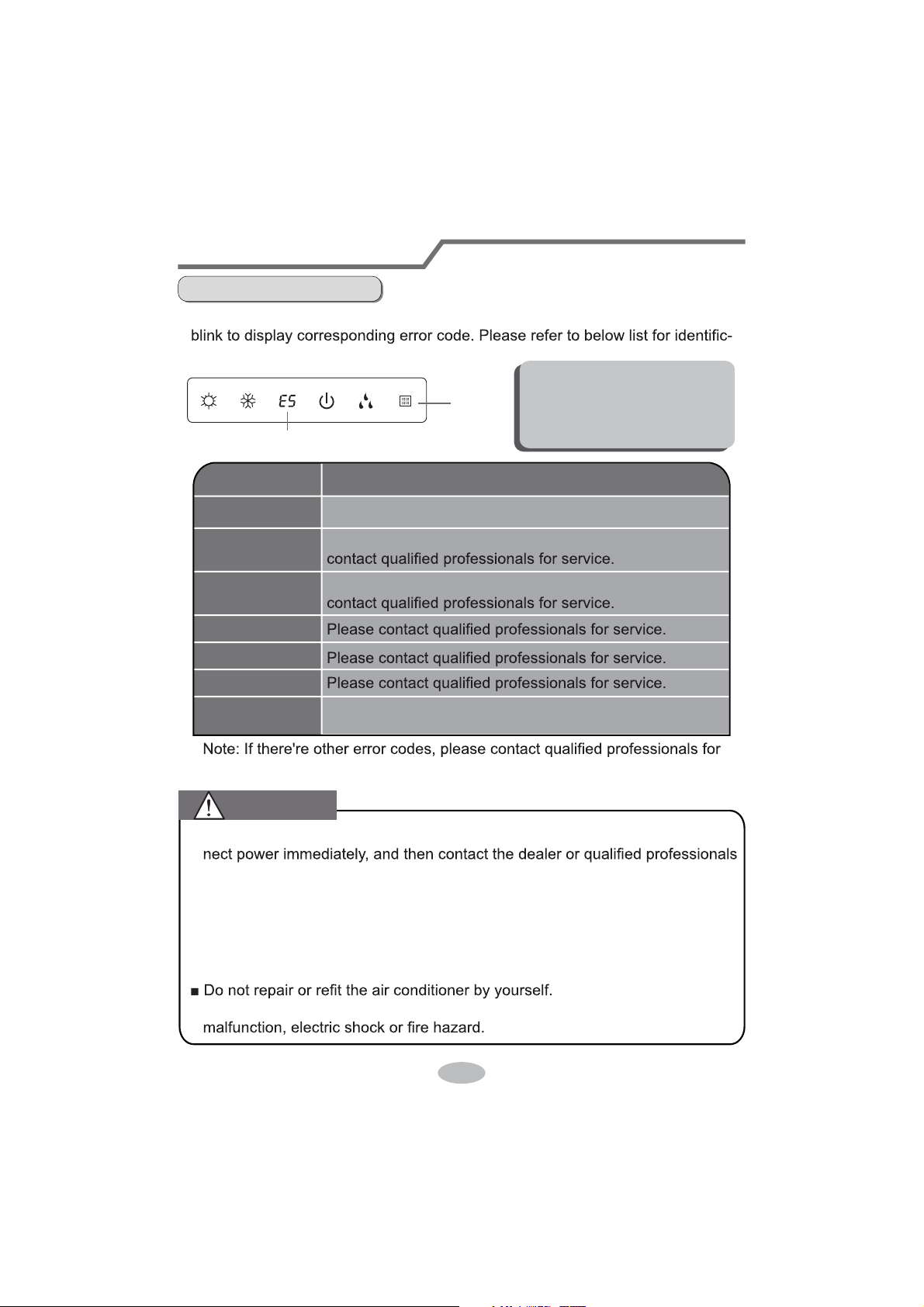
Error Code
Ɣ When air conditioner status is abnormal, temperature indicator on indoor unit will
ation of error code.
Indoor
display
Error code
Above indicator diagram is only
for reference. Please refer to
actual product for the actual
indicator and position.
service.
Error code
E5
H6
C5
F1
F2
E6
Troubleshooting
t
It can be eliminated af er restarting the unit. If not, please
It can be eliminated after restarting the unit. If not, please
Means defrosting status. It’s the normal phenomenon.
Heating indicator
ON 10s OFF 0.5s
It can be eliminated after restarting the unit. If not, please
contact qualified professionals for service.
Ŷ:KHQEHORZSKHQRPHQRQRFFXUVSOease turn off air conditioner and discon-
for service.
Ɣ3RZHUFRUGLVRYHUKHDWLQJRUGDPDJHG
Ɣ There’s abnormal sound during operation.
Ɣ Air switch trips off frequently.
Ɣ Air conditioner gives off burning smell.
Ɣ,QGRRUXQLWLVOHDNLQJ
Ŷ,IWKHDLUFRQGLWLRQHURSHUDWHVXQGHUDbnormal conditions, it may cause
WARNING
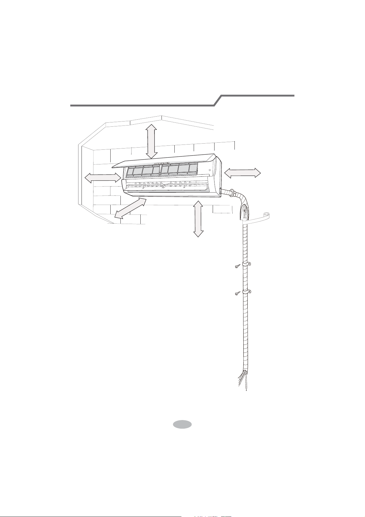
21
Installation dimension diagram
At least 250cm
At least 15cm
At least 300cm
6SDFHWRWKHÀRRU
Space to the ceiling
Space to the obstruction
At least 15cm
At least 15cm
Space to the wall
Space to the wall
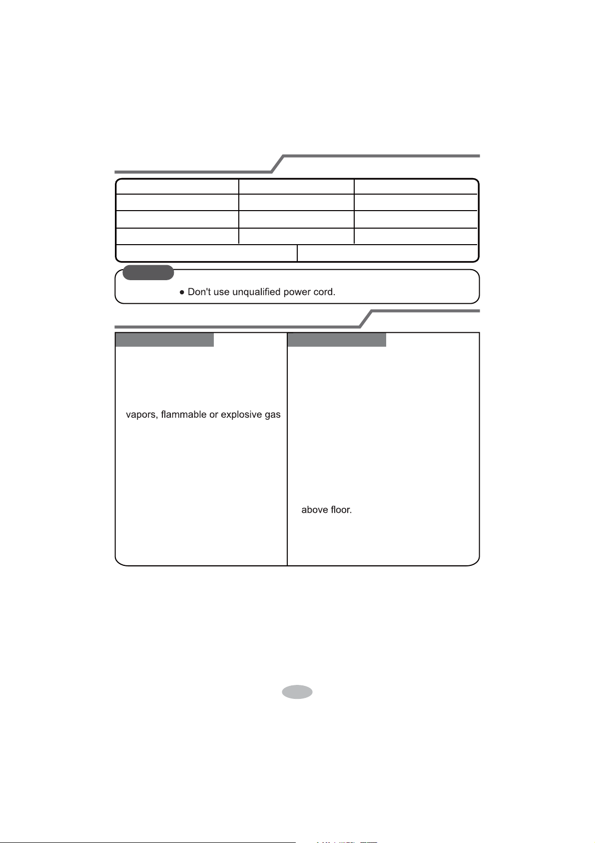
22
Selection of installation location
Basic requirement
Installing the unit in the following pla-
ces maycause malfunction. If it is un-
avoidable, please consult the local
dealer:
1. There should be no obstruction near air
inlet and air outlet.
2. Select a location where the condensat-
ion water can be dispersed easily and
won't affect other people.
3. Select a location which is convenient to
connect the outdoor unit and near the
power socket.
4. Select a location which is out of reach
for children.
5.
The location should be able to withstand
the weight of indoor unit and won't incr-
ease noise and vibration.
6.
The appliance must be installed 2.5m
7. Don't install the indoor unit right above
the electric appliance.
Indoor unit
1.The place with strong heat sources,
,
8. Please try your best to keep way from
fluorescent lamp.
or volatile objects spread in the air.
2.The place with high-frequency
devices (such as welding machine,
medical equipment).
3.The place near coast area.
4.
The place with oil or fumes in the air.
5.The place with sulfureted gas.
6.Other places with special circums-
tances.
7.The appliance shall not be install-
ed in the laundry
Tools for installation
1 Level meter 2 Screw driver 3 Impact drill
4 Drill head 5 Pipe expander 6 Torque wrench
7 Open-end wrench 8 Pipe cutter 9 Leakage detector
10 Vacuum pump 11 Pressure meter 12 Universal meter
13 Inner hexagon spanner 14 Measuring tape
Note:
Ɣ3OHDVHFRQWDFWWKHORFDODJHQWIRULQVWDOODWLRQ
23
Requirements for electric connection
Safety precaution
Grounding requirement
1. Must follow the electric safety regulations when installing the unit.
circuit break.
3. Make sure the power supply matches with the requirement of air conditioner.
Unstable power supply or incorrect wiring or malfunction. Please install proper
power supply cables before using the air conditioner.
4. Properly connect the live wire, neutral wire and grounding wire of power socket.
5. Be sure to cut off the power supply before proceeding any work related to
electricity and safety.
7. If the supply cord is damaged, it must be replaced by the manufacturer, its
8. The temperature of refrigerant circuit will be high, please keep the interconnec-
tion cable away from the copper tube.
grounding with specialized grounding device by a professional. Please make
sure it is always grounded effectively, otherwise it may cause electric shock.
2. The yellow-green wire in air conditioner is grounding wire, which can't be used
for other purposes.
3. The grounding resistance should comply with national electric safety regulations.
4. The appliance must be positioned so that the plug is accessible.
5. An all-pole disconnection switch having a contact separation of at least 3mm in
6. Including an circuit break with suitable capacity, please note the following table.
Circuit break should be included magnet buckle and heating buckle function, it
can protect the circuit-short and overload. (Caution: please do not use the fuse
only for protect the circuit)
9. The appliance shall be installed in accordance with national wiring regulations.
10. Installation must be performed in accordance with the requirement of NEC
and CEC by authorized personnel only.
24
Installation of indoor unit
Step one: choosing installation location
Step two: install wall-mounting frame
rm it with the client.
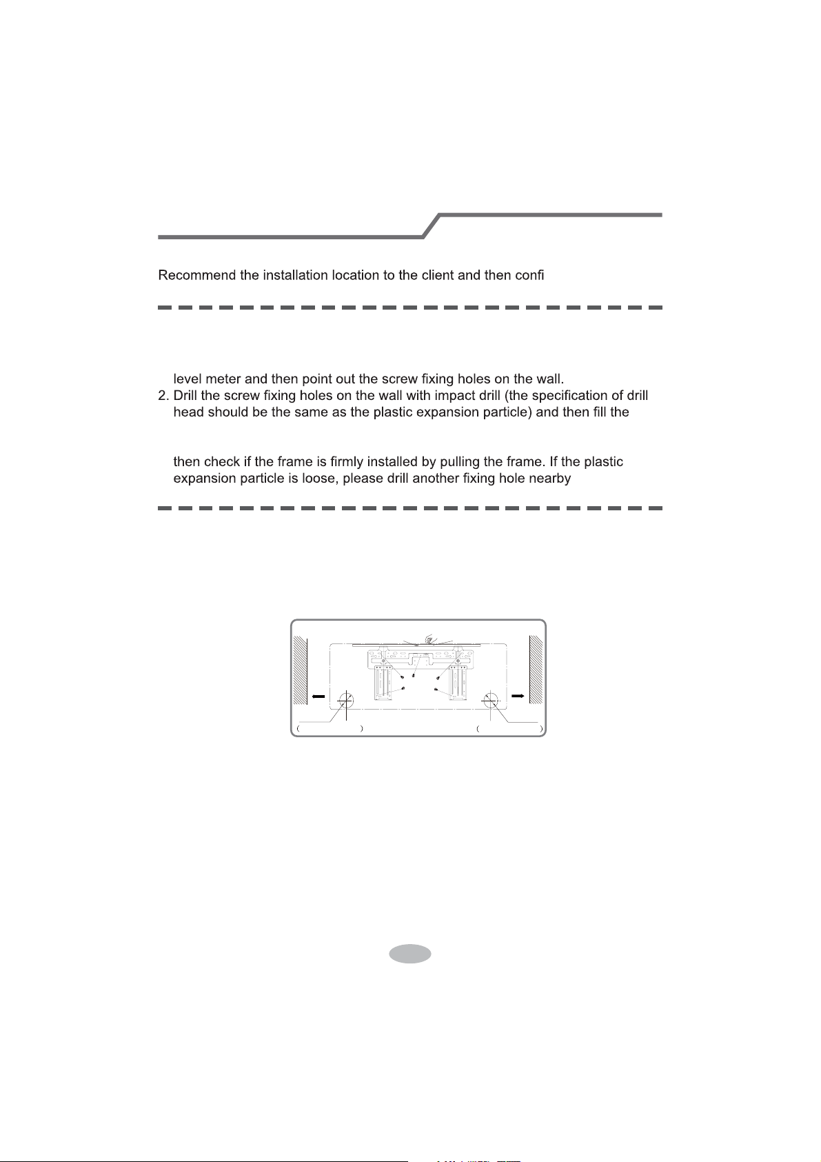
1. Hang the wall-mounting frame on the wall; adjust it in horizontal position with the
plastic expansion particles in the holes.
3. Fix the wall-mounting frame on the wall with tapping screws (ST4.2X25TA) and
.
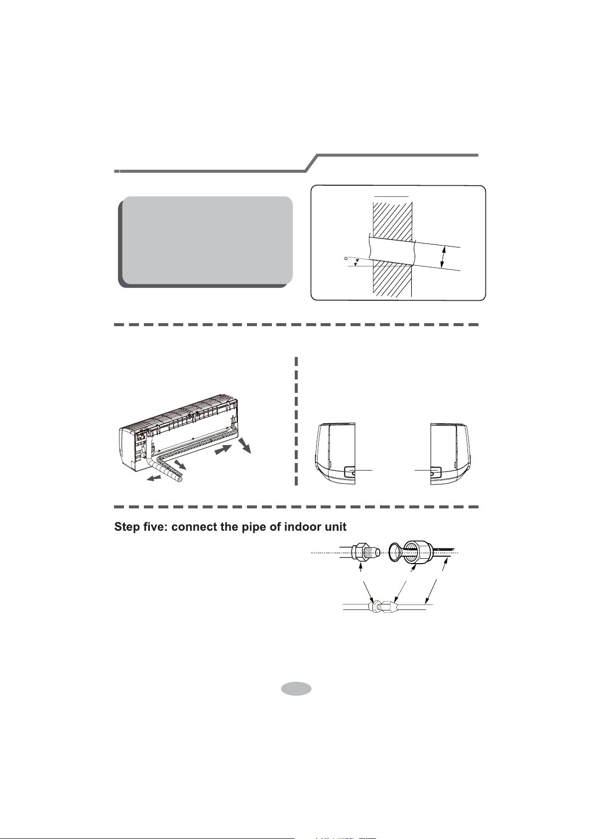
1. Choose the position of piping hole according to the direction of outlet pipe. The
position of piping hole should be a little lower than the wall-mounted frame,
shown as below.
Step three: open piping hole
2. Open a piping hole with the diameter ofĭRQWKHVHOHFWHGRXWOHWSLSH
position. In order to drain smoothly, slant the piping hole on the wall slightly
GRZQZDUGWRWKHRXWGRRUVLGHZLWKWKHJUDGLHQWRI
Left
Wall
ĭPP
Right
Mark in the middle of it
Level meter
Rear piping hole
Wall
Space
to the
wall
above
PP
Space
to the
wall
above
PP
ĭPP
Rear piping hole
25
1. Aim the pipe joint at the corresponding
bellmouth.
2. Pretightening the union nut with hand.
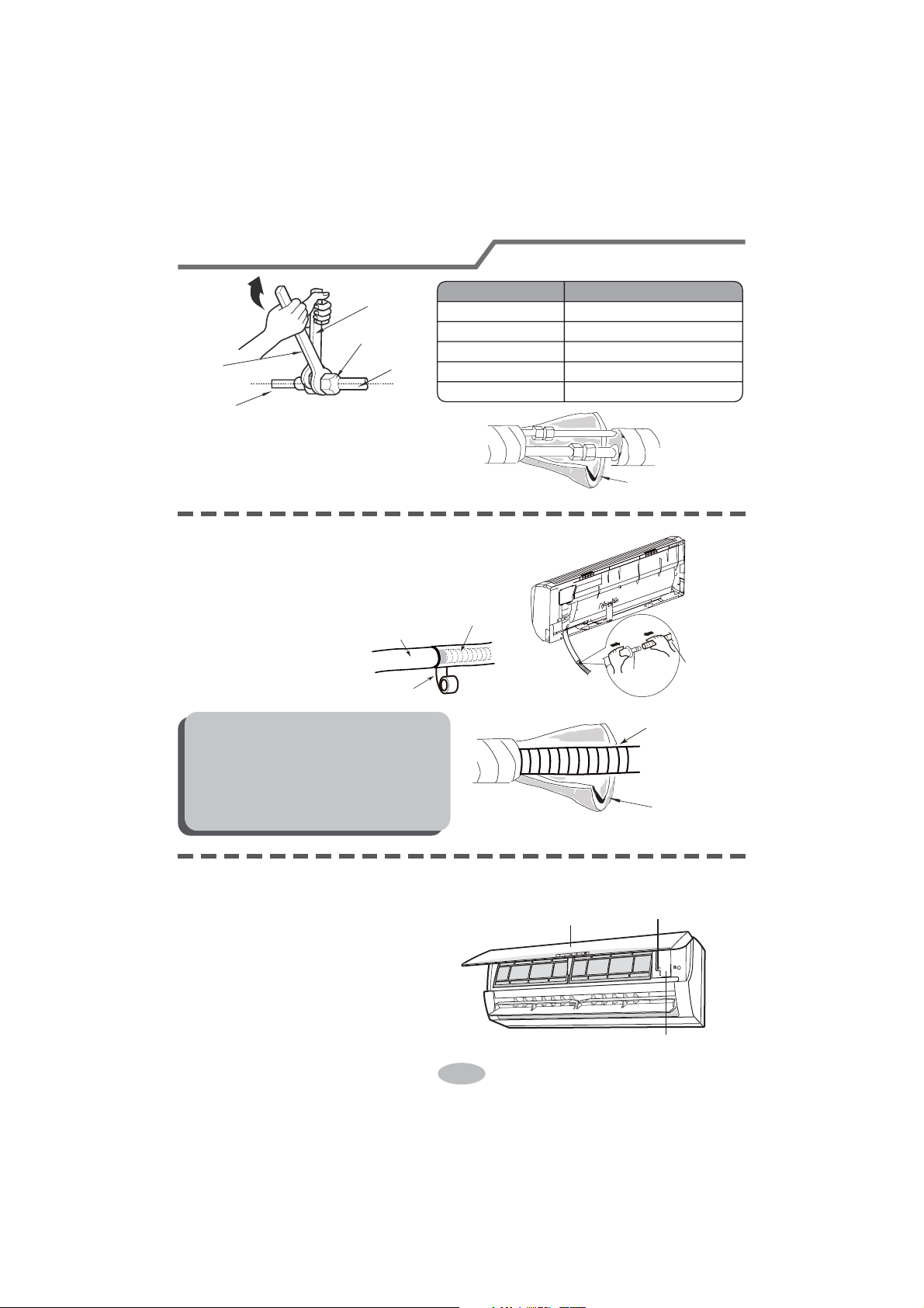
3. Adjust the torque force by referring to the following sheet. Place the open-end
wrench on the pipe joint and place the torque wrench on the union nut. Tighten
the union nut with torque wrench.
2. When select leading out the pipe
from left or right, please cut off the
corresponding hole on the bottom
case.
cut off
the hole
left right
1. The pipe can be led out in the
direction of right, rear right, left or
rear left.
left
rear left
right
rear right
Step four: outlet pipe
Installation of indoor unit
union nutpipe joint
pipe
Note:
Ɣ3D\DWWHQWLRQWRGXVWSUHYHQWLRQDQG
WDNHUHOHYDQWVDIHW\PHDVXUHVZKHQ
opening the hole.
Ɣ The plastic expansion particles are
QRWSURYLGHGDQGVKRXOGEHERXJKW
locally.
Indoor
5-10
outdoor
ĭ
26
nection pipe with insulating pipe, and
insulating pipe
1. Connect the drain hose to the outlet pipe of
outlet
pipe
drain hose
drain hose
tape
outlet pipe
drain hose
insulating pipe
Ɣ Add insulating pipe in the indoor
Ɣ The plastic expansion particles are
1. Open the panel, remove the screw
on the wiring cover and then take
wiring cover
screw
panel
Step seven: connect wire of indoor unit
4. Wrap the indoor pipe and joint of con-
then wrap it with tape.
Step six: install drain hose
Installation of indoor unit
torque wrench
open-end
wrench
indoor pipe
pipe
union nut
Hex nut diameter Tightening torque (N
.
m)
ĭ
ĭ
ĭ
ĭ
ĭ
30~40
45~55
60~65
70~75
15~20
indoor unit.
2. Bind the joint with tape.
Note:
drain hose in order to prevent
condensation.
not provided.
down the cover.
27
4. Put wiring cover back and then tighten the screw.
5. Close the panel.
Installation of indoor unit
Note:
Ɣ All wires of indoor unit and outdoor unit should be connected by a professional.
for a new one. Avoid extending the cord by yourself.
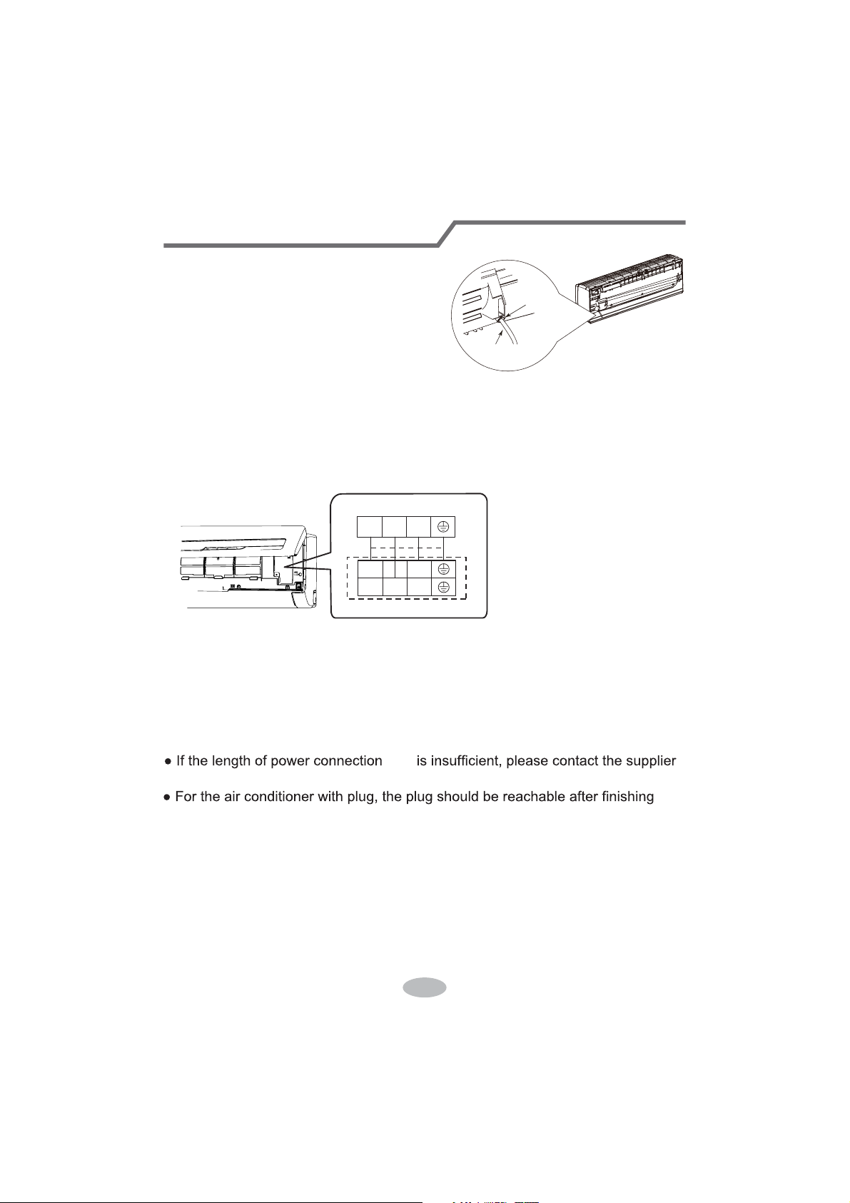
3. Remove the wire clip; connect the power connection cord to the wiring terminal
with wire clip.
power connection
cord
cable-cross
hole
2. Make the power connection cord go
through the cable-cross hole at the back
of indoor unit and then pull it out from
the front side.
23N(1)
Outdoor unit connection
L2L1
23N(1)
cord
according to the color ;tighten the screws and then fix the power connection cord
fixed by the wire clip inside of the electric box first before connecting the power
connection cord.
If there is no wired controller in the product you bought ,you should put the wire
installation.
Ɣ)RUWKHDLUFRQGLWLRQHUZLWKRXWSOXJDQ circuit break must be installed in the line.
The air switch should be all-pole parting and the contact parting distance should
be more than 3mm.
28
Installation of indoor unit
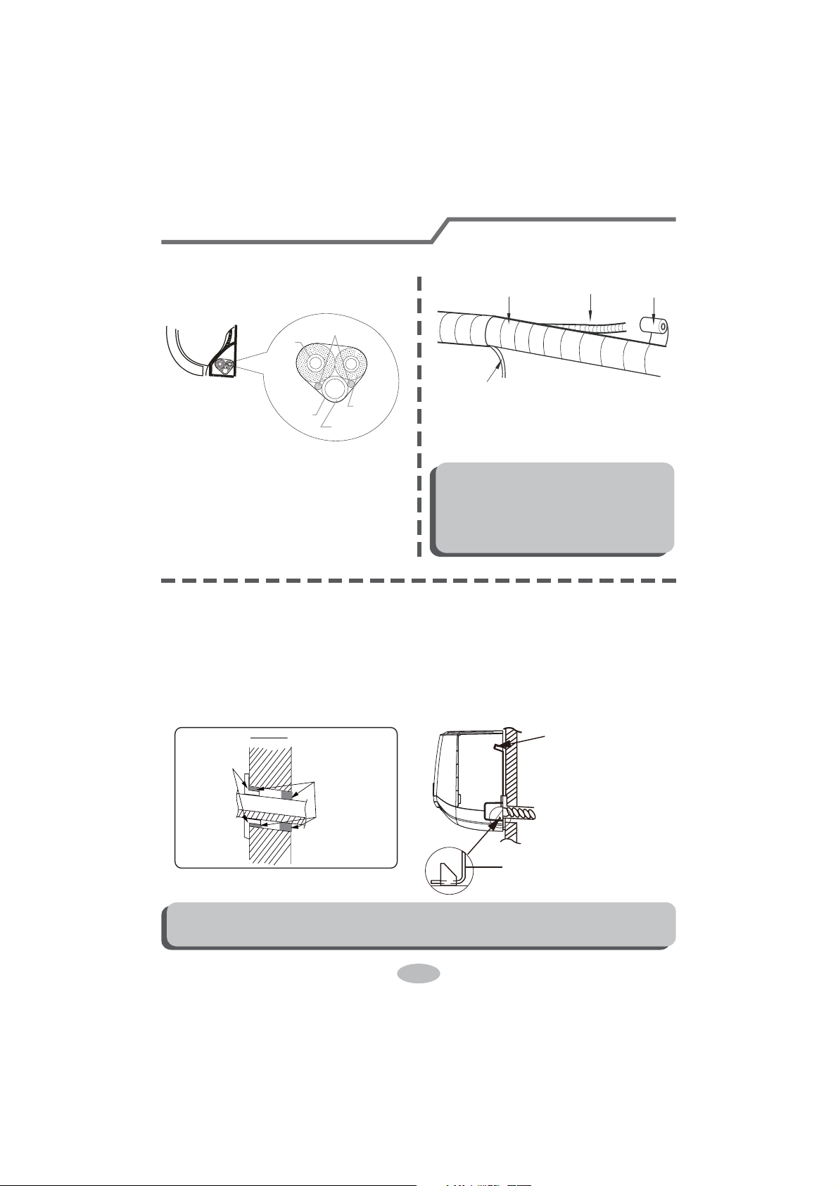
Step eight: bind up pipe
1. Bind up the connection pipe, power
cord and drain hose with the band.
indoor unit
gas
pipe
indoor and
outdoor power cord
liquid pipe
drain hose
band
2. Reserve a certain length of drain
hose and power cord for installation
when binding them. When binding to
a certain degree, separate the indoor
power and then separate the drain
hose.
3. Bind them evenly.
4. The liquid pipe and gas pipe should
be bound separately at the end.
Note:
Ɣ7KHSRZHUFRUGDQGFRQWUROZLUH
FDQWEHFURVVHGRUZLQGLQJ
Ɣ7KHGUDLQKRVHVKRXOGEHERXQG
at the bottom.
drain hose
band
connection pipe
indoor power cord
Step nine: hang the indoor unit
1. Put the bound pipes in the wall pipe and then make them pass through the wall
hole.
2. Hang the indoor unit on the wall-mounting frame.
3. Stuff the gap between pipes and wall hole with sealing gum.
4. Fix the wall pipe.
5. Check if the indoor unit is installed firmly and closed to the wall.
Note:
Ɣ'RQRWEHQGWKHGUDLQKRVHWRRH[FHVVLYHO\LQRUGHUWRSUHYHQWEORFNLQJ
indoor
outdoor
wall pipe
sealing gum
upper hook
lower hook of
wall-mounting frame
29
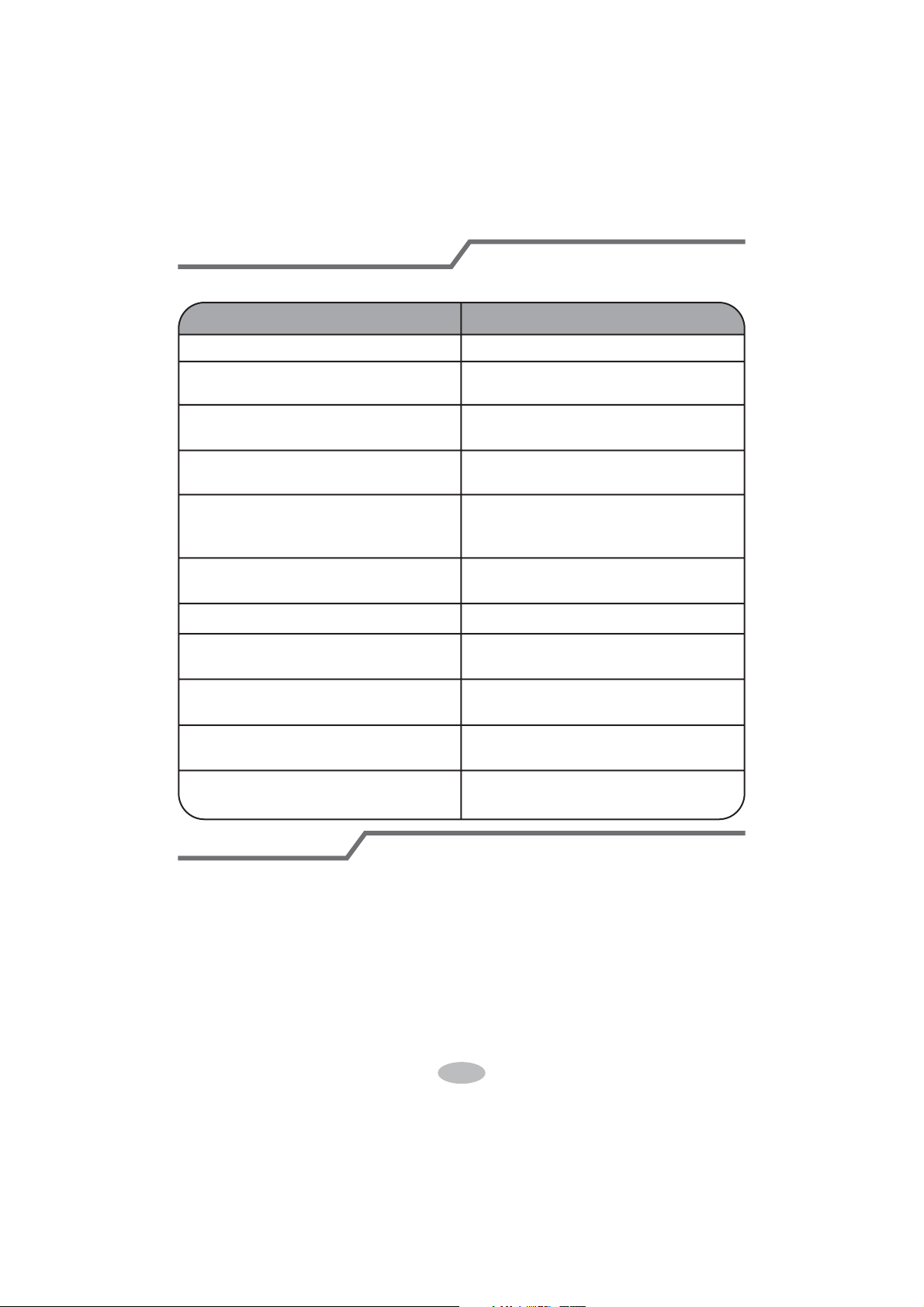
Check after installation
Test operation
Ɣ&KHFNDFFRUGLQJWRWKHIROORZLQJUHTXLUHPHQWDIWHU¿QLVKLQJLQVWDOODWLRQ
Items to be checked Possible malfunction
+DVWKHXQLWEHHQLQVWDOOHG¿UPO\" The unit may drop, shake or emit noise.
Have you done the refrigerant leakage
test?
,WPD\FDXVHLQVXI¿FLHQWFRROLQJ
(heating) capacity.
,VKHDWLQVXODWLRQRISLSHOLQHVXI¿FLHQW"
It may cause condensation and water
dripping.
Is water drained well?
It may cause condensation and water
dripping.
Is the voltage of power supply accord-
ing to the voltage marked on the
nameplate?
It may cause malfunction or damaging
the parts.
Is electric wiring and pipeline installed
correctly?
It may cause malfunction or damaging
the parts.
Is the unit grounded securely? It may cause electric leakage.
Does the power cord follow the speci-
¿FDWLRQ"
It may cause malfunction or damaging
the parts.
Is there any obstruction in the air inlet
and outlet?
,WPD\FDXVHLQVXI¿FLHQWFRROLQJ
(heating) capacity.
The dust and sundries caused during
installation are removed?
It may cause malfunction or damaging
the parts.
The gas valve and liquid valve of
connection pipe are open completely?
,WPD\FDXVHLQVXI¿FLHQWFRROLQJ
(heating) capacity.
1. Preparation of test operation
Ɣ7KHFOLHQWDSSURYHVWKHDLUFRQGLWLRQHU
Ɣ6SHFLI\WKHLPSRUWDQWQRWHVIRUDLUFRQGLWLRQHUWRWKHFOLHQW
2. Method of test operation
Ɣ3XWWKURXJKWKHSRZHUSUHVV212))EXWWRQRQWKHUHPRWHFRQWUROOHUWRVWDUW
operation.
Ɣ3UHVV02'(EXWWRQWRVHOHFW$872&22/'5<)$1DQG+($7WRFKHFN
whether the operation is normal or not.
Ɣ,IWKHDPELHQWWHPSHUDWXUHLVORZHUWKDQ
ć
, the air conditioner can’t
start cooling.
30
1. Standard length of connection pipe
ƔPPP
4. The additional refrigerant oil and refrigerant charging required after prolonging
connection pipe
Ɣ $IWHUWKHOHQJWKRIFRQQHFWLRQSLSHLVSURORQJHGIRUPDWWKHEDVLVRI
VWDQGDUGOHQJWK\RXVKRXOGDGGPORIUHIULJHUDQWRLOIRUHDFKDGGLWLRQDOP
of connection pipe.
Ɣ The calculation Pethod of additional refrigerant charging DPount (on the Easis
of liquid pipe):
ƔBasing on the length of standard pipe, add refrigerant according to the
requirement as shown in the table. 7KHDGGLWLRQDOUHIULJHUDQWFKDUJLQJDPRXQW
SHUPHWHULVGLfIHUHQWDFFRUGLQJWRWKHGLDPHWHURIOLTXLGSLSH6HHWKH
following sheet.
$GGLWLRQDOUHIULJHUDQWFKDUJLQJDPRXQW = prolonged length of liquid pipe ×
DGGLWLRQDOUHIULJHUDQWFKDUJLQJDPRXQWSHUPHWHU
Cooling
FDSDFLW\
Cooling
FDSDFLW\
%WXK
:
%WXK
:
%WXK
:
%WXK
:
%WXK
:
%WXK
:
%WXK
:
%WXK
:
%WXK
:
%WXK
:
Max height
difference
Max height
difference
Max length
of connec-
tion pipe
Max length
of connec-
tion pipe
10
10
20
20 10 20
10 20
0LQOHQJWKRIFRQQHFWLRQSLSHLVP
0D[OHQJWKRIFRQQHFWLRQSLSHDQGPD[KLJKGLfference.
Configuration of connection pipe
31
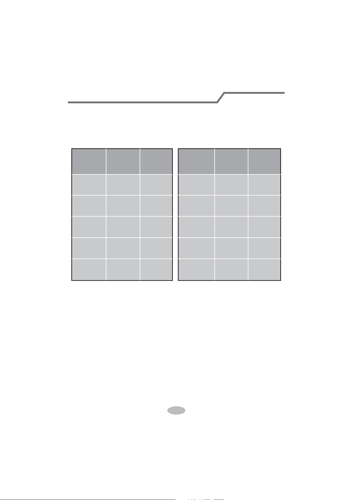
Additional refrigerant charging amount for R22, R407C, R410A and R134a
Diameter of connection pipe
Liquid pipe(mm) Gas pipe(mm)
ĭ
ĭRUĭ
ĭRUĭ
ĭ
ĭ
ĭ
ĭ
ĭRUĭ
ĭRUĭ
ĭRUĭ
_
_
Cooling only(g/m) Cooling and heating(g/m)
15
15
30
60
250 250
350350
120
120
50
20
Outdoor unit throttle
&RQ¿JXUDWLRQRIFRQQHFWLRQSLSH
32
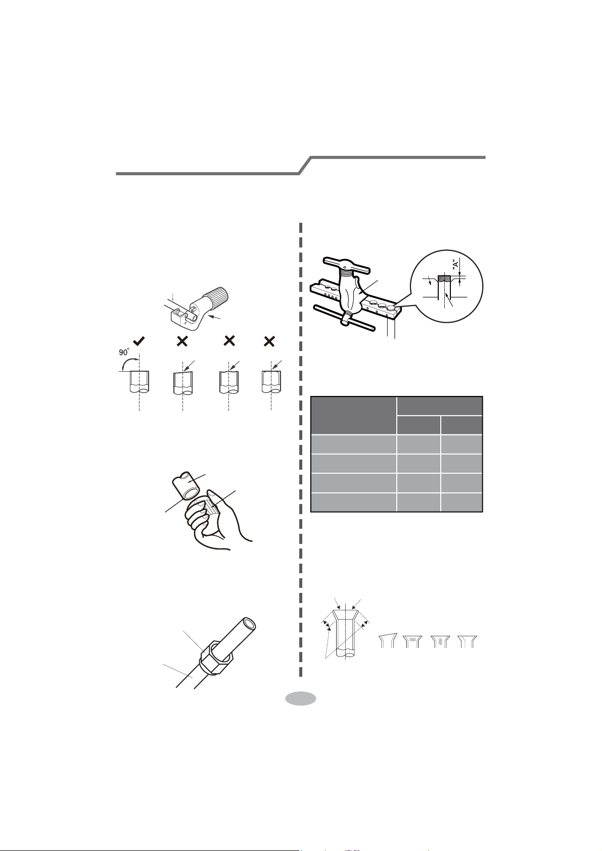
Pipe expanding method
Note:
Improper pipe expanding is the main cause of refrigerant leakage. Please expand
the pipe according to the following steps:
A: Cut the pipe
Ɣ&RQ¿UPWKHSLSHOHQJWKDFFRUGLQJWR
the distance of indoor unit and
outdoor unit.
Ɣ&XWWKHUHTXLUHGSLSHZLWKSLSHFXWWHU
pipe
pipe cutter
leaning uneven burr
B: Remove the burrs
Ɣ5HPRYHWKHEXUUVZLWKVKDSHUDQG
prevent the burrs from getting into
the pipe.
downwards
pipe
shaper
C: Put on suitable insulating pipe
D: Put on the union nut
Ɣ5HPRYHWKHXQLRQQXWRQWKHLQGRRU
connection pipe and outdoor valve;
install the union nut on the pipe.
union pipe
pipe
E: Expand the port
Ɣ([SDQGWKHSRUWZLWKH[SDQGHU
Note:
Ɣ$LVGLIIHUHQWDFFRUGLQJWRWKH
diameter, please refer to the sheet
below:
expander
hard
mold
pipe
F: Inspection
Ɣ&KHFNWKHTXDOLW\RIH[SDQGLQJSRUW
If there is any blemish, expand the
port again according to the steps
above.
the length is equal
improper expanding
leaning
damaged
surface
crack uneven
thickness
smooth surface
Outer diameter
(mm)
A(mm)
Max Min
ĭ
ĭ
ĭ
ĭ
1.3 0.7
1.6 1.0
1.8 1.0
2.4 2.2
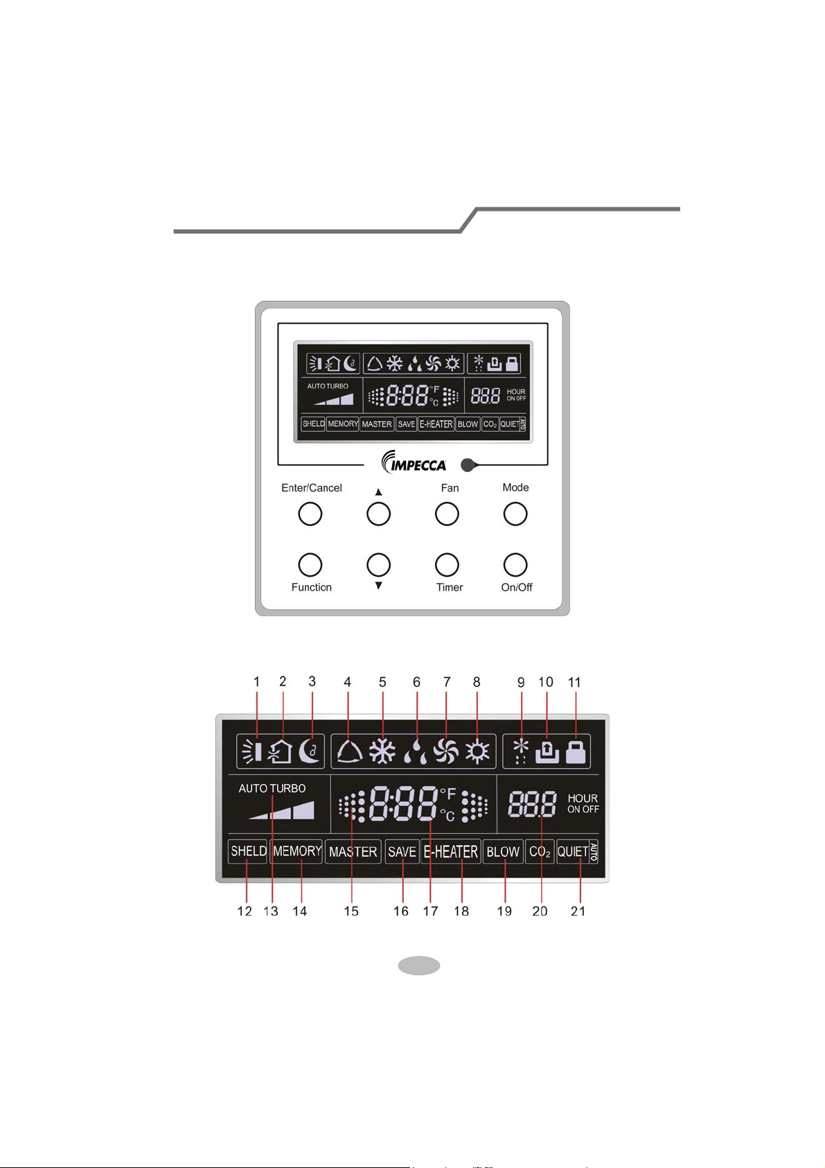
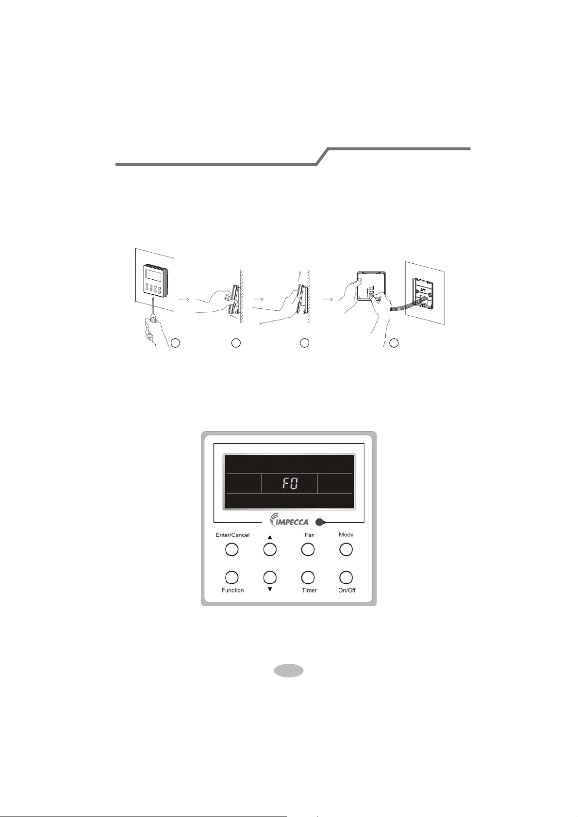
1 Displaying Part
Fig1.1.1 Outline of wired controller
1.1 LCD Display of Wired Controller
Fig.1.1.2 LCD display
33
If the product you bought is equipped with wired controller, please
refer to the following introductions of wired controller.
Wired Controller (Optional)
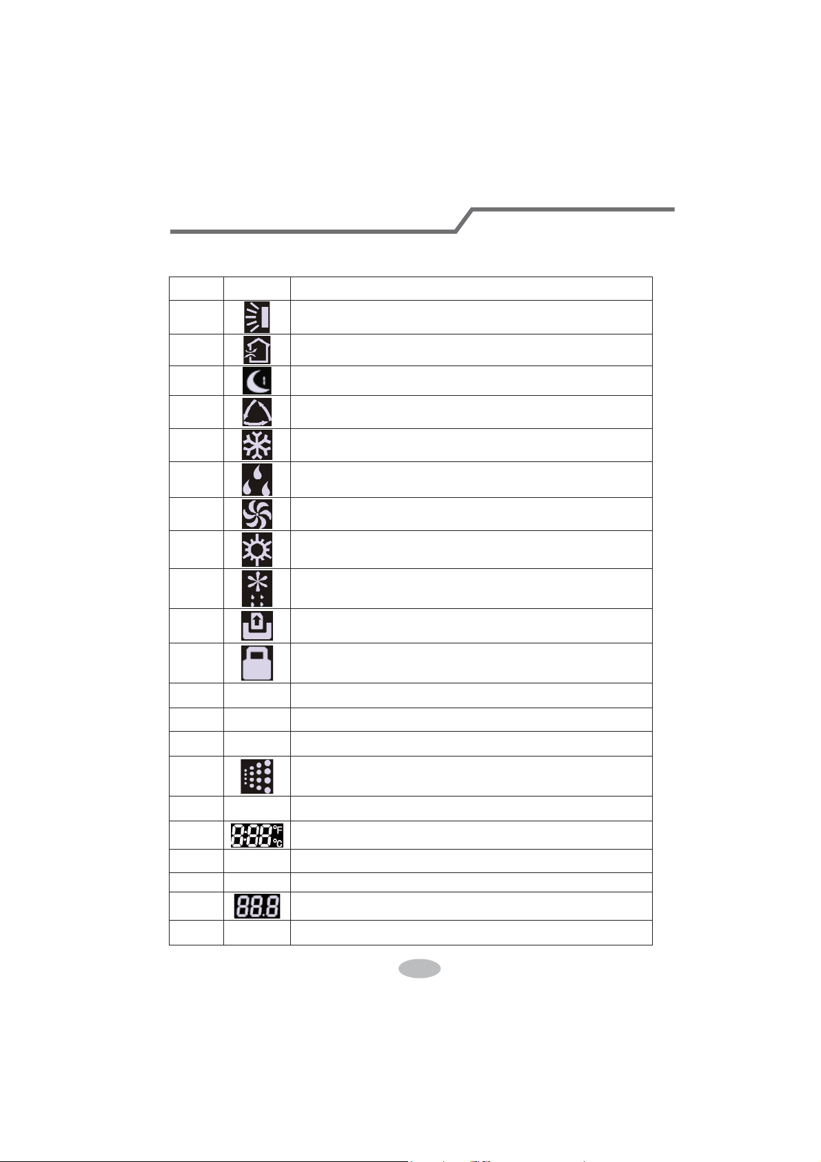
1.2 Instruction to LCD Display
Table 1.1
No. Symbols Description
1
Swing function
2
Air exchange function (this function is yet unavailable for this unit).
3
Sleep function (Only sleep 1).
4
Each kind of running mode of indoor unit (auto mode)
5
Cooling mode
6
Dry mode
7
Fan mode
8
Heating mode
9
Defrosting function for the outdoor unit.
10
Gate-control function (this function is yet unavailable for this unit).
11
Lock function.
12 SHIELD
Shield functions (Button operation, temperature setting, On/Off operation,
Mode setting are disabled by the remote monitoring system.)
13 Turbo Turbo function state
14 MEMORY
Memory function (The indoor unit resumes the original setting state after
power failure and then power recovery).
15
It blinks under on state of the unit without operation of any button.
16
SAVE
Energy-saving function (this function is yet unavailable for this unit).
17
Ambient/setting temperature value
18 E-HEATER Electric auxiliary heating function.
19 BLOW Blow function.
20
Timing value.
21 QUIET
Quiet function (two types: quiet and auto quiet)
(this function is yet unavailable for this unit).
34
Wired Controller (Optional)
2 Buttons
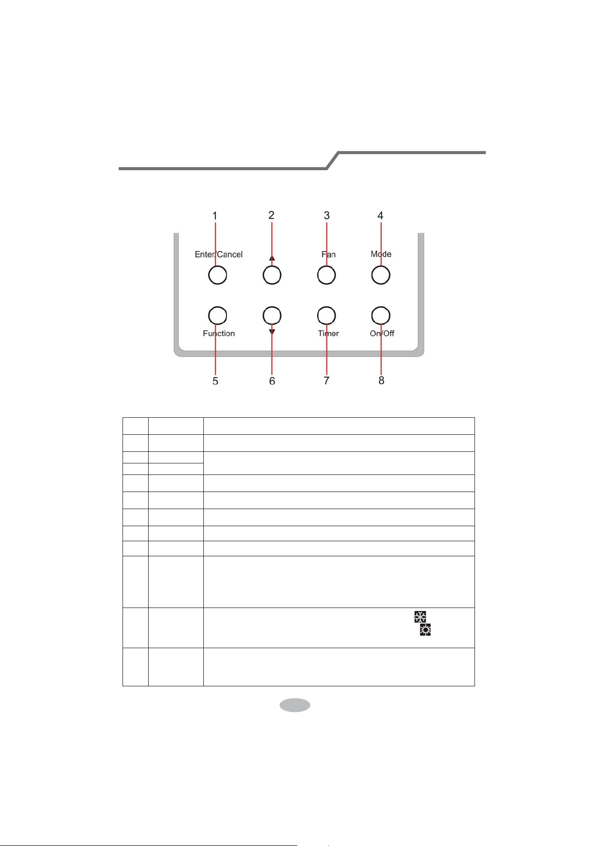
2.1 Layout of Buttons
2.2 Functions of Buttons
Table 2.1
No. Name Function
1 Enter/Cancel Function selection and cancellation.
2 Ÿ
ķ .
Running temperature setting of the indoor unit, range:16~30
o
C.
ĸ .
Timer setting, range:0.5-24 hr.
6 ź
3 Fan Setting of the high/middle/low/auto fan speed.
4 Mode Setting of the Cooling/Heating/Fan/Dry/Auto mode of the indoor unit.
5 Function Switchover among the functions of Turbo/Save/E-heater/Blow etc..
7 Timer Timer setting.
8 On/Off Turn on/off the indoor unit
4+2 Ÿ0RGH
Press them for 5s under off state of the unit to enter/cancel the Memory
function(If memory is set, indoor unit after power failure and then power
recovery will resume the original setting state. If not, the indoor unit is
defaulted to be off after power recovery. Memory off is default before
delivery.).
3+6 )DQź
By pressing them at the same time under off state of the unit,
will be
displayed on the wired controller for the cooling only unit, while
will be
displayed on the wired controller for the cooling and heating unit.
2+6 Ÿź
Upon startup of the unit without malfunction or under off state of the
unit,press them at the same time for 5s to enter the lock state, in which
case,any other buttons won’t respond the press. Repress them for 5s to quit
this state.
35
Wired Controller (Optional)
3 Operation Instructions
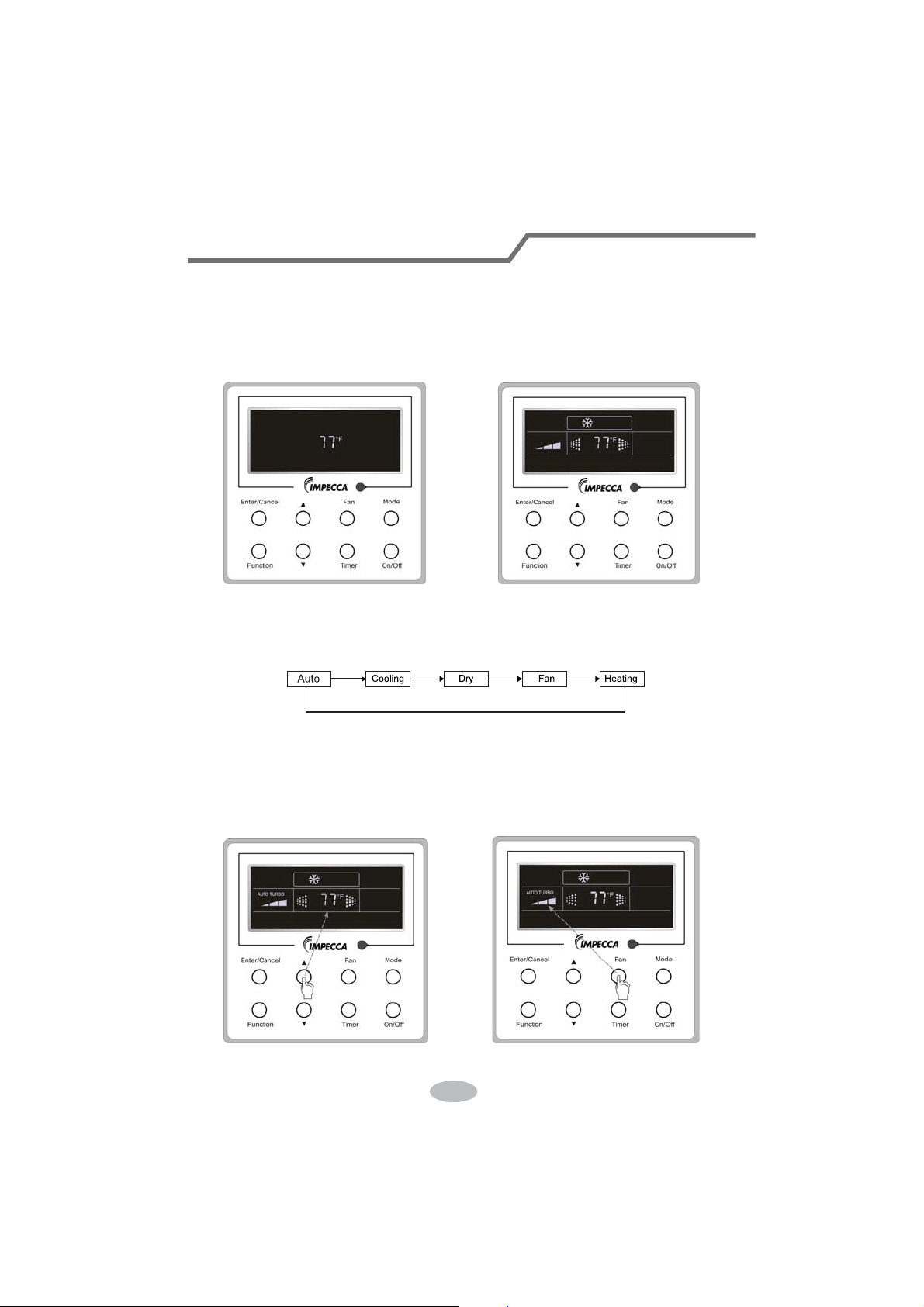
3.1 On/Off
Press On/Off to turn on the unit and turn it off by another press.
Note: The state shown in Fig.3.1.1 indicates the “Off” state of the unit after power on. The state
shown in Fig.3.1.2 indicates the “On” state of the unit after power on.
Fig.3.1.1 “Off” State Fig.3.1.2 “On” State
3.2 Mode Setting
Under ON state of the unit, press the Mode to switch the operation modes as the following
sequence: Auto–Cooling–Dry–Fan–Heating.
3.3 Temperature Setting
Press Ÿor ź to increase/decrease the preset temperature. If pressing either of them
continuously, the temperature will be increased or decreased by 1°C every 0.5s,as shown in
Fig.3.3.1.
In the Cooling, Dry, Fan or Heating mode, the temperature setting range is 16°C~30°C.
In the Auto mode, the setting temperature is unadjustable.
Fig.3.3.1 Fig.3.4.1
36
Wired Controller (Optional)
3.4 Fan Setting
Under the “On” state of the unit, press Fan and then fan speed of the indoor unit will change
circularly as shown in Fig.3.4.1.
Low Middle
High
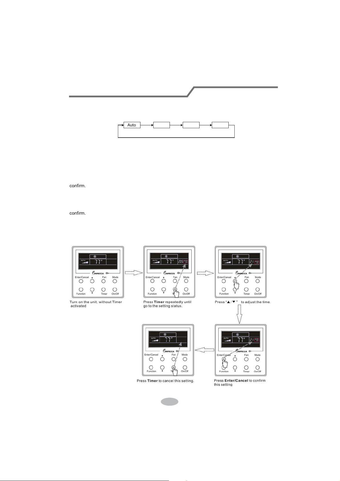
3.5 Timer Setting
Under on-state of the unit, Press Timer button to set timer off of the unit. Under off-state of the
unit, press Timer button to set timer on of the unit in the same way.
Timer on setting:
Under off-state of the unit without timer setting, if Timer button is pressed, LCD will display xx.
Hour,with ON blinking. In this case, SUHVVŸ or ź button to adjust timer on and then press Timer to
Timer off setting:
Under on-state of the unit without timer setting, if Timer button is pressed, LCD will display xx.
HourZLWK2))EOLQNLQJ,QWKLVFDVHSUHVVŸRUźEXWWRQWRDGMXVWWLPHURQDQGWKHQSUHVV Timer to
&DQFHOWLPHU
After setting of timer, if Timer button is pressed, LCD won’t display xx. Hour so that timer setting
is canceled.
Timer off setting under the “On” state of the unit is shown as Fig.3.5.1.
Fig.3.5.1 Timer off Setting under the “On” State of the Unit
37
Wired Controller (Optional)
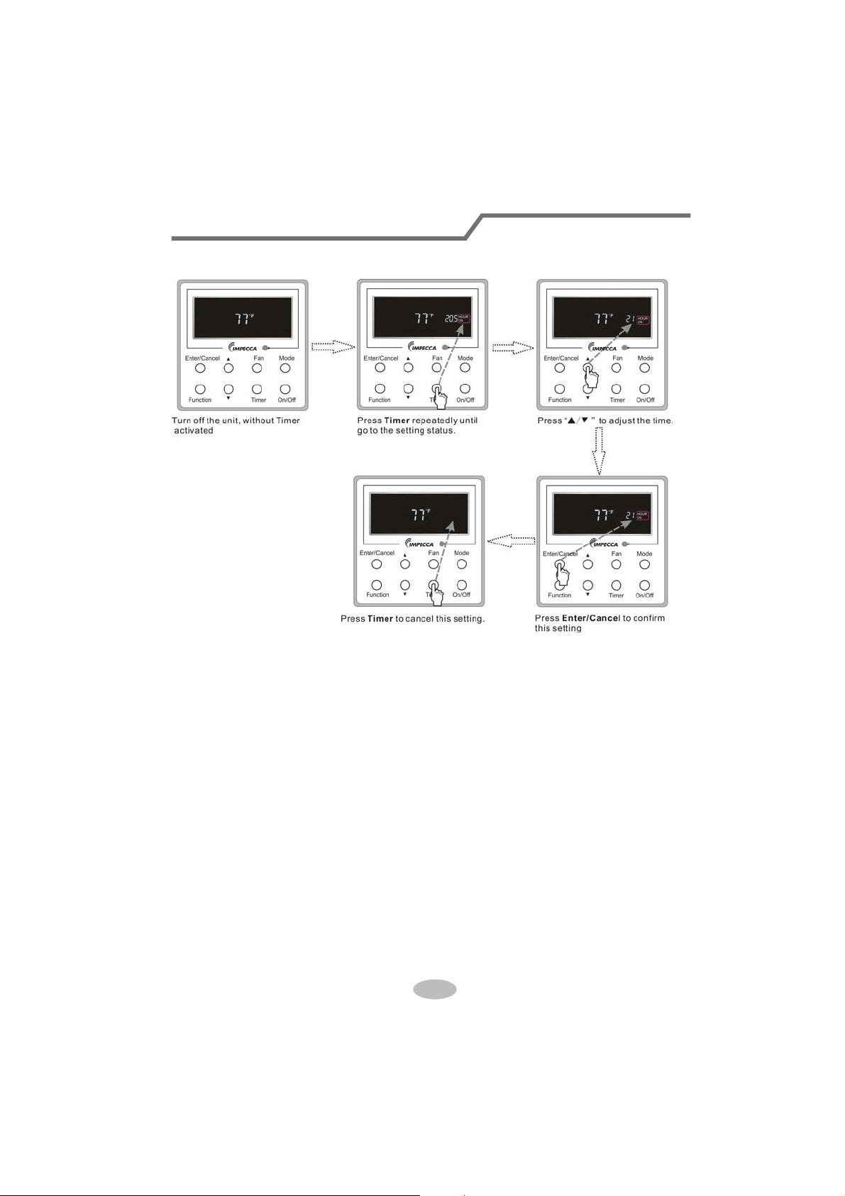
Timer on setting under the “Off” state of the unit is shown as Fig.3.5.2.
Fig.3.5.2 Timer on Setting under the “Off” State of the Unit
Timer range: 0.5-24hr. Every press of ŸRU ź will make the set time increased or decreased by
0.5hr. If either of them is pressed continuously, the set time will increase/ decrease by 0.5hr every
0.5s.
38
Wired Controller (Optional)
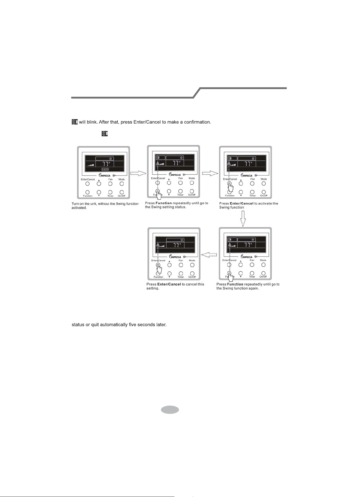
3.6 Swing Setting
Swing On: Press Function under on state of the unit to activate the swing function. In this case,
Swing Off: When the Swing function is on, press Function to enter the Swing setting
interface,with
blinking. After that, press Enter/Cancel to cancel this function. Swing setting is
shown as Fig.3.6.1.
Fig.3.6.1 Swing Setting
Notes:
ķ .
Sleep, Turbo or Blow setting is the same as the Swing setting.
ĸ .
After the setting has been done, it has to press the key “Enter/Cancel” to back to the setting
39
Wired Controller (Optional)
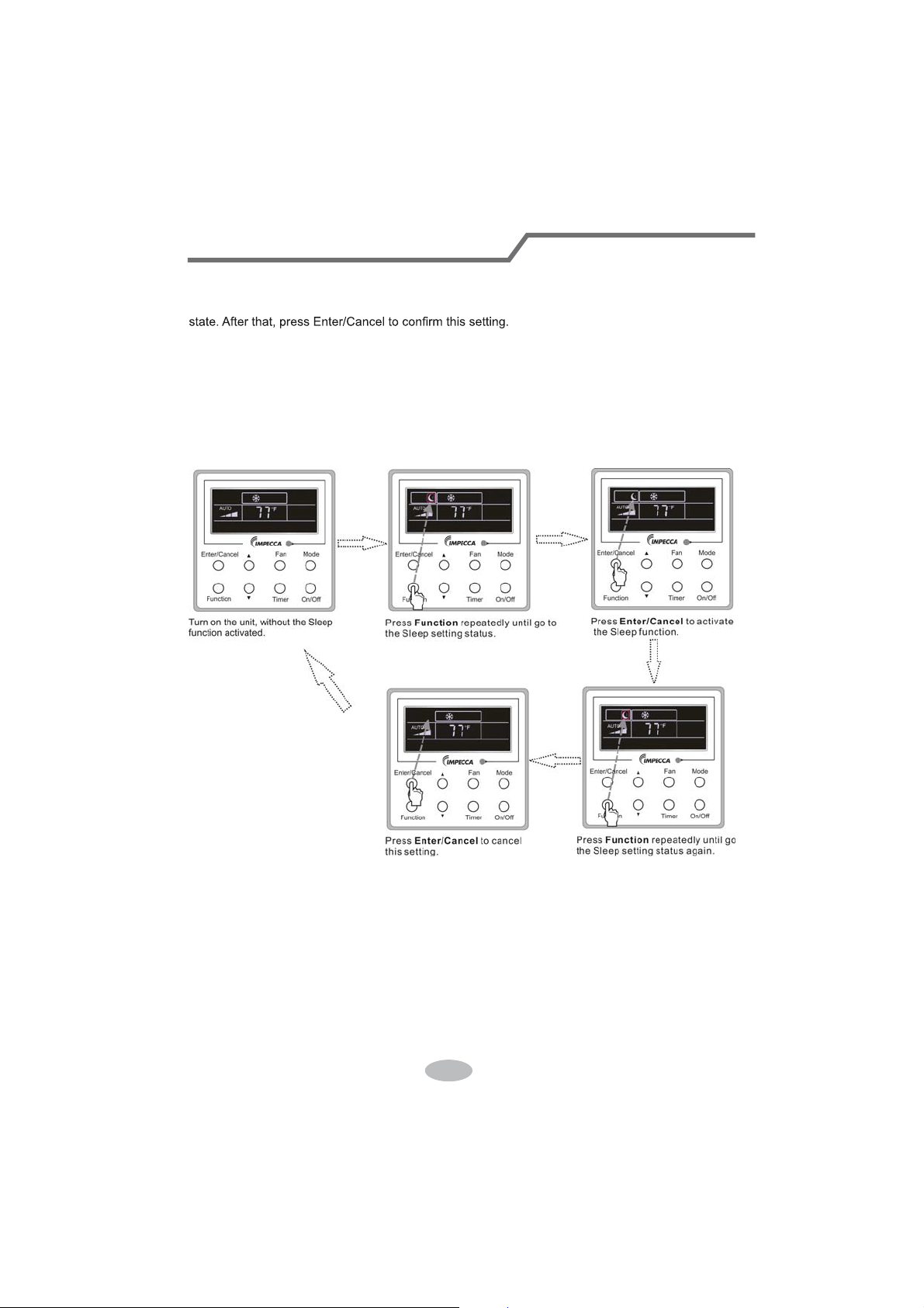
3.7 Sleep Setting
Sleep on: Press Function under the On state of the unit till the unit enters the Sleep setting
Sleep off: When the Sleep function is activated, press Function to enter the Sleep setting
status. After that, press Enter/Cancel to cancel this function.
In the Cooling or Dry mode, the temperature will increase by 1°C after the unit runs under
Sleep1 for 1hr and 1°C after another 1hr.After that, the unit will run at this temperature.
In the Heating mode, the temperature will decrease by 1°C after the unit runs under Sleep 1 for
1hr and 1°C after another 1hr. After that, the unit will run at this temperature.
Sleep setting is shown as Fig.3.7.1.
Fig.3.7.1. Sleep Setting
40
Wired Controller (Optional)
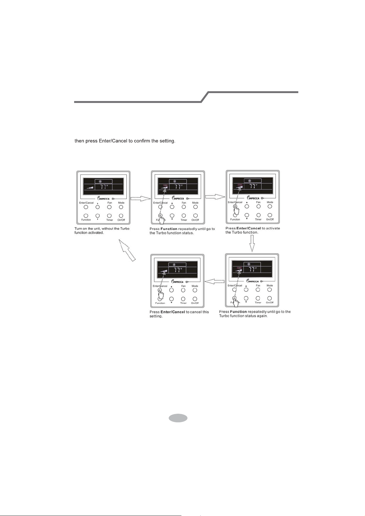
3.8 Turbo Setting
Turbo function: The unit at the high fan speed can realize quick cooling or heating so that the
room temperature can quickly approach the setting value.
In the Cooling or Heating mode, press Function till the unit enters the Turbo setting status and
When the Turbo function is activated, press Function to enter the Turbo setting status and then
press Enter/Cancel to cancel this function.
Turbo function setting is as shown in Fig.3.8.1.
Fig.3.8.1 Turbo Setting
41
Wired Controller (Optional)
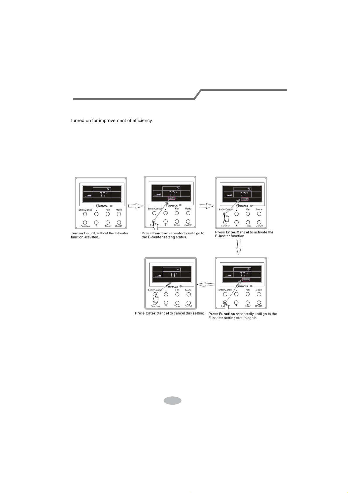
3.9 E-heater Setting
E-heater (auxiliary electric heating function): In the Heating mode, E-heater is allowed to be
Once the wired controller or the remote controller enters the Heating mode, this function will be
turned on automatically.
Press Function in the Heating mode to enter the E-heater setting interface and then press
Enter/Cancel to cancel this function.
Press Function to enter the E-heater setting status, if the E-heater function is not activated,
and then press Enter/Cancel to activate it.
The setting of this function is shown as Fig.3.9.1 below:
Fig.3.9.1 E-heater Setting
42
Wired Controller (Optional)

3.10 Blow Setting
Blow function: After the unit is turned off, the water in evaporator of indoor unit will be
automatically evaporated to avoid mildew.
In the Cooling or Dry mode, press Function till the unit enters the Blow setting status and then
press Enter/Cancel to active this function.
When the Blow function is activated, press Function to the Blow setting status and then press
Enter/Cancel to cancel this function.
Blow function setting is as shown in Fig.3.10.1
Fig.3.10.1 Blow Setting
Notes:
ķ .
When the Blow function is activated, if turning off the unit by pressing On/Off or by the
remote controller, the indoor fan will run at the low fan speed for 2 min, with “BLOW” displayed on
the LCD. While, if the Blow function is deactivated, the indoor fan will be turned off directly.
ĸ .
Blow function is unavailable in the Fan or Heating mode.
43
Wired Controller (Optional)
3.11 Other Functions
a. Lock
Upon startup of the unit without malfunction or under the “Off” state of the unit, press Ÿ and źat
the same time for 5s till the wired controller enters the Lock function. In this case, LCD displays
.
After that, repress these two buttons at the same time for 5s to quit this function.
Under the Lock state, any other button press won’t get any response.
b. Memory
Memory switchover: Under the “Off” state of the unit, press Mode and Ÿ at the same time for
5s to switch memory states between memory on and memory off. When this function is activated,
Memory will be displayed. If this function is not set, the unit will be under the “Off” state after power
failure and then power recovery.
Memory recovery: If this function has been set for the wired controller, the wired controller after
power failure will resume its original running state upon power recovery. Memory contents: On/
Off, Mode, set temperature, set fan speed and Lock function.
4 Installation and Dismantlement
4.1 Connection of the Signal Line of the Wired Controller
Ɣ2SHQWKHFRYHURIWKHHOHFWULFFRQWUROER[RIWKHLQGRRUXQLW
Ɣ/HWWKHVLQJOHOLQHRIWKHZLUHGFRQWUROOHUWKURXJKWKHUXEEHUULQJ
Ɣ&RQQHFWWKHVLJQDOOLQHRIWKHZLUHGFRQWUROWRWKHSLQVRFNHWRIWKHLQGRRUXQLW3&%
Ɣ Tighten the signal wire with ties.
Ɣ The communication distance between the main board and the wired controller can be up to
20 meters ( the standard distance is 8 meters)
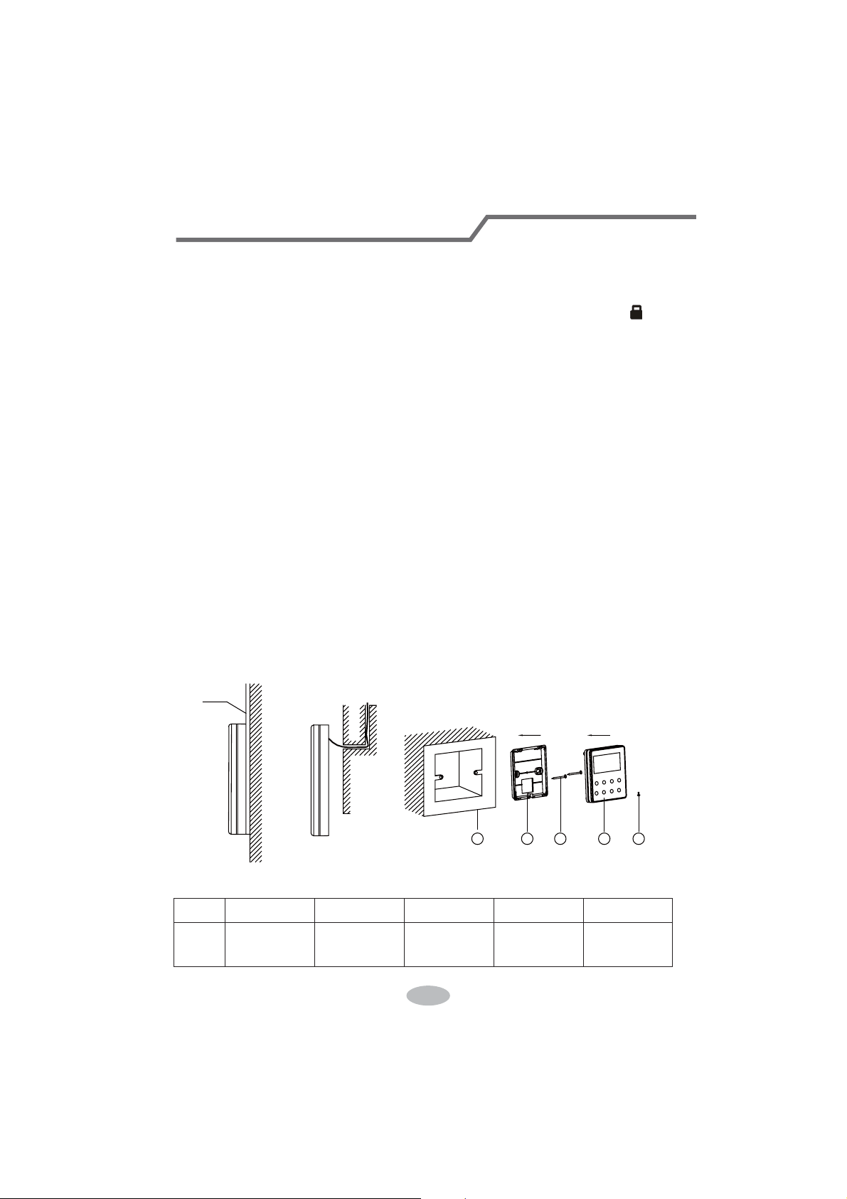
4.2 Installation of the Wired Controller
1
39&3LSH
3 4 52
Fig.4.1 Accessories for the Installation of the Wired Controller
Table 4.1
No. 1 2 3 4 5
Name
6RFNHWER[
embedded
in the wall
Soleplate of
the Wired
Controller
Screw
M4X25
)URQW3DQHO
of the Wired
Controller
Screw
ST 2.9X6
44
Wired Controller (Optional)
1
6
8 9
10
7
3 4
5
2
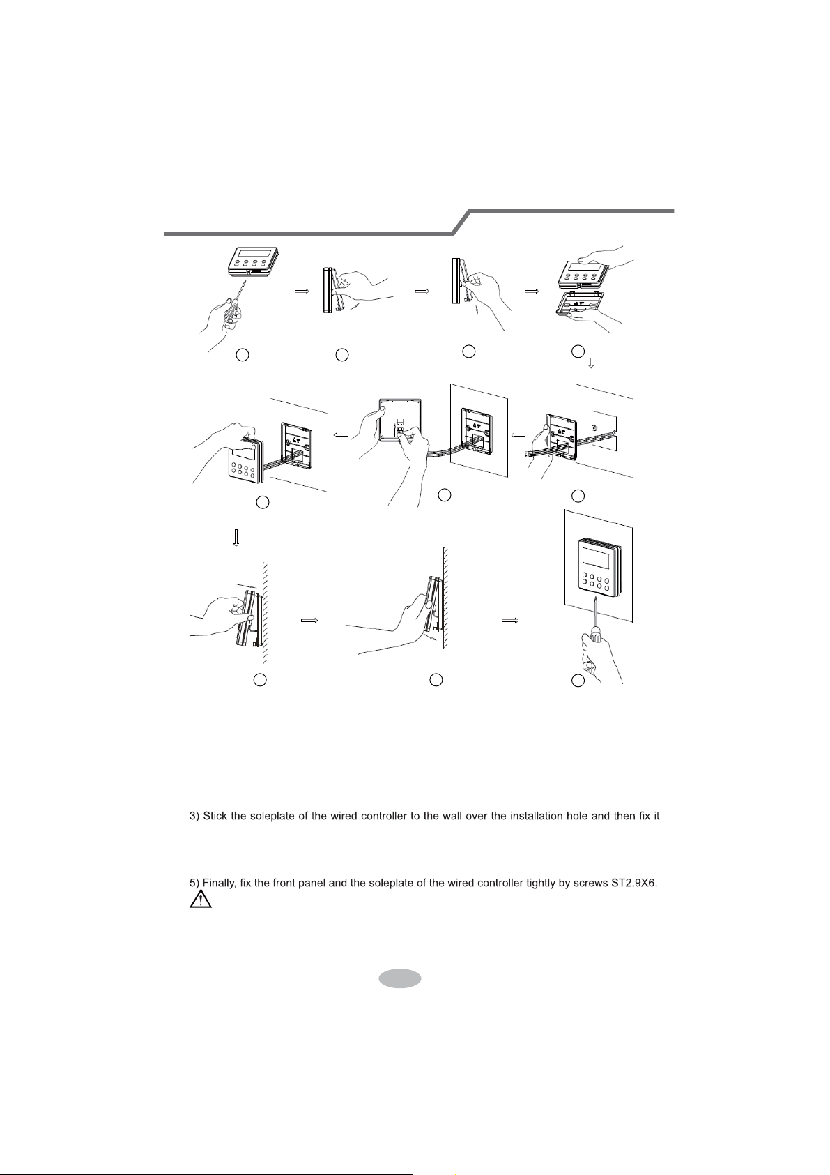
Fig.4.2
Fig.4.2 shows the installation steps of the wired controller, but there are some issues that need
your attention.
1) Prior to the installation, please firstly cut off the power supply of the wire buried in the
installation hole, that is, no operation is allowed with electricity during the whole installation.
2) Pull out the four-core twisted pair line from the installation holes and then let it go through
the rectangular hole behind the soleplate of the wired controller.
with screws M4X25.
4) Insert the four-core twisted pair line into the slot of the wired controller and then buckle the
front panel and the soleplate of the wired controller together.
CAUTION!
Please pay special attention to the followings during the connection to avoid the malfunction of
the air conditioning unit due to electromagnetic interference.
ķ .
Separate the signal and communication lines of the wired controller from the power cord
45
Wired Controller (Optional)
and connection lines between the indoor and outdoor unit, with a minimum interval of 20cm,
otherwise the communication of the unit will probably work abnormally.
ĸ .
If the air conditioning unit is installed where is vulnerable to electromagnetic
interference,then the signal and communication lines of the wired controller must be the shielding
twisted pair lines.
4.3 Dismantlement of the Wired Controller
1 3 42
5 Errors Display
If there is an error occurring during the operation of the system, the error code will be displayed
on the LCD, as show in Fig.5.1. If multi errors occur at the same time, their codes will be displayed
circularly.
Note: In event of any error, please turn off the unit and contact the professionally skilled
personnel.
Fig.5.1
46
Wired Controller (Optional)
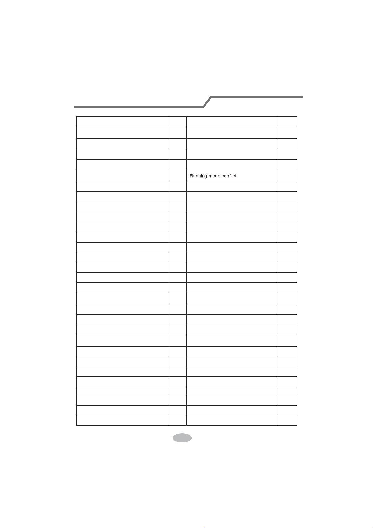
Table 5.1 Meaning of Each Error
Error
Error
Code
Error
Error
Code
Return air temperature sensor open/
short circuited
F1 Drive board communication error P6
evaporator temperature sensor open/
short circuited
F2 Compressor overheating protection H3
Indoor unit liquid valve temperature
sensor open/short circuited
b5 Indoor and outdoor units unmatched LP
Indoor gas valve temperature sensor
open/ short circuited
b7
Communication line misconnected or
expansion valve error
dn
IPM temperature sensor open/short
circuited
P7 E7
Outdoor ambient temperature sensor
open/ short circuited
F3 Pump-down Fo
Outdoor unit condenser mid-tube
temperature sensor open/short circuited
F4 Jumper error C5
Discharge temperature sensor open/
short circuited
F5 Forced defrosting H1
Indoor and outdoor communication error E6 Compressor startup failure Lc
DC bus under-voltage protection PL High discharge temperature protection E4
DC bus over-voltage protection PH Overload protection E8
Compressor phase current sensing
circuit error
U1 Whole unit over-current protection E5
Compressor demagnetization protection HE Over phase current protection P5
PFC protection Hc Compressor desynchronizing H7
IPM Temperature Protection P8 IPM Current protection H5
Over-power protection L9
Compressor phase loss/reversal
protection
Ld
System charge shortage or blockage
protection
F0
Frequency restricted/reduced with whole
unit current protection
F8
Capacitor charging error PU
Frequency restricted/reduced with IPM
current protection
En
High pressure protection E1
Frequency restricted/reduced with high
discharge temperature
F9
Low pressure protection E3
Frequency restricted/reduced with anti-
freezing protection
FH
Compressor stalling LE
Frequency restricted/reduced with
overload protection
F6
Over-speeding LF
Frequency restricted/reduced with IPM
temperature protection
EU
Drive board temperature sensor error PF Indoor unit full water error E9
AC contactor protection P9 Anti-freezing protection E2
Temperature drift protection PE AC input voltage abnormal PP
Sensor connection protection Pd Whole unit current sensing circuit error U5
DC bus voltage drop error U3 4-way valve reversing error U7
Outdoor fan 1 error protection L3 Motor stalling H6
Outdoor fan 2 error protection LA PG motor zero-crossing protection U8
47
Wired Controller (Optional)

CUSTOMER S
UPPORT
Before contacting customer support, please see the troubleshooting guide above.
Visit our website to contact us, find answers to Frequently Asked Questions, and for other
resources which may include an updated version of this user's guide.
WWW.IMPECCA.COM
If you wish to contact us by phone, please be sure to have your model number and serial
number ready and call us between 9:00am and 6:00pm ET, at +1 866-954-4440.
Keep tabs on Impecca's newest innovations & enter contests via our social network feeds:
www.facebook.com/Impecca/
www.instagram.com/impecca/
@impeccausa

© 2016 Impecca, a division of LT Inc., Wilkes Barre, PA.

Owner's Manual
Split Type Wall-mounted Air Conditioner
Model:
ISMO-1821
Thank you for choosing our product.
For proper operation, please read and keep this manual carefully.
If you have lost the Owner’s Manual, please contact the local agent or
visit www.impecca.com for an electronic version.
v
. 1.1
CONTENTS
GENERAL INFORMATION
1
2
3
4
4
5
8
6
7
7
8
Technical Data
Electrical Connections
Installing The Outdoor Unit
Maintenance
Installation Dimension Diagram
Check After Installation
Bleeding
Conformity And Range
The Instructions Before Use
Name of Parts
Outdoor Unit Working Temperature Range
GENERAL
INSTALLER
INFORMATION
The products in this manual may be different with the rea one, according to different models, l
some models have displayer and some models without displayer, the position and shape of
the displayer please refer to the real one.
In line with the company
’s policy of continual product improvement, the aesthetic and dimensional
characteristics, technical data and accessories of this appliance may be changed without notice.
This appliance is not intended for use by persons (including children) with reduced physical,
sensory or mental capabilities, or lack of experience and knowledge, unless they have been
given supervision or instruction concerning use of the appliance by a person responsible for
their safety.
Children should be supervised to ensure that they do not play with the appliance.
This marking indicates that this product should not be disposed with other
household wastes throughout the EU. To prevent possible harm to the
environment or human health from uncontrolled waste disposal, recycle
it responsibly to promote the sustainable reuse of material resources. To
return your used device, please use the return and collection systems or
contact the retailer where the product was purchased. They can take this
product for environmental safe recycling.
Explanation of Symbols
Indicates a hazardous situation that, if not avoided, will result in death
or serious injury.
Indicates a hazardous situation that, if not avoided, could result in death
or serious injury.
Indicates a hazardous situation that, if not avoided, may result in minor
or moderate injury.
Indicates important but not hazard-related information, used to indicate
risk of property damage.
Indicates a hazard that would be assigned a signal word
WARNING or CAUTION.
CONFORMITY AND RANGE
GENERAL INFORMATION
Please read this owner's manual carefully before operating the unit and keep it carefully for consultation.
Only use the air conditioner as instructed in this booklet. These instructions are not intended to
cover every possible condition and situation. As with any electrical household appliance, common sense
and caution are therefore always recommended for installation, operation and maintenance.
1
Instructions for installation and use of this product are provided by the manufacturer.
THE INSTRUCTIONS BEFORE USE GENERAL INFORMATION
WARNING
When having a burning smell or
smoke,please turn off the power
supply and contact with the ser-
vice center.
If the abnormity still exists,the unit
may be damaged,and may cause
electric shock or fire.
Power must adopts the special
circuit to prevent fire.
Otherwise, it can cause electric
shock or fire.
Disconnect the power supply if
long putting the air conditioner
out of use.
Otherwise,the accumulated dusts
may cause overheating or fire.
Never damage the electric wire
or use the electric wire which is
not appointed.
Otherwise,it will cause overheating
or fire.
When cleaning,it is necessary
to stop driving and turn off the
power supply.
Cut off power supply
Otherwise,it may cause electric
shock or damage.
The power supply must adopt the
special circuit that with air switch
protection and assure it has enou-
gh capacity.The unit will be turned
on or off according to your requir-
ement automatically,please do not
turn on or turn off the unit freque-
ntly,otherwise disadvantage effect
may be caused to the unit.
Rated voltage of this air conditi-
oner 220-240V, 60Hz, The com-
pressor will vibrate sharply if the
voltage is too low, resulting in
damage to refrigerating system.
Electrical component are easy to
damage if the voltage is too high.
Don't attempt to repair the air
conditioner by yourself.
The wrong repair will lead to an
electric shock or fire,so you should
contact the service center to repair.
Don't step on the top of the
outdoor unit or place something
on it.
If it is damaged, it may lead to the
fall of the unit and cause the injury.
Please note whether the insta-
lled stand is firm enough or not.
Earthing: The unit must be reli-
ably earthed.The earthing cable
shall be connected to the spec-
ial earthing device in the const-
ruction.
As falling off the outdoor unit can be
dangerous.
Never cut off or damage power
cables and control wires. If the
power cable and signal control
wire were damaged, change
them by professional.
2
★ ★
★ ★
★
★
★ ★
★ ★
★
★
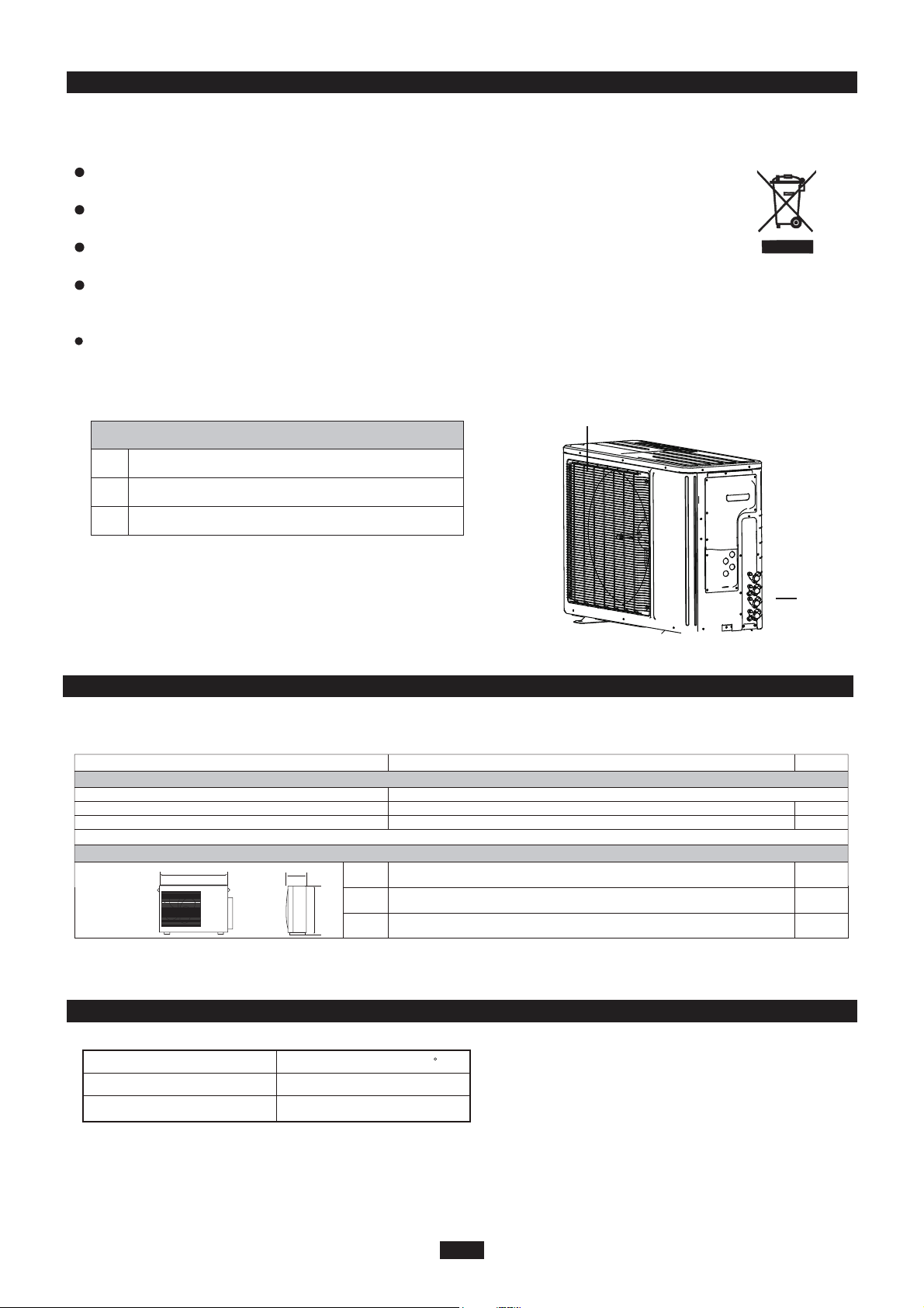
OUTDOOR UNIT
No. Description
1 Air outlet grille
2 Valve
Be sure to cut off the power supply before cleaning the air conditioner; otherwise electric
shock might happen.
Wetting of air conditioner may cause the risk of electric shock. Make sure not to wash
your air conditioner in any case.
This product must not be disposed together with the domestic waste.
This product has to be disposed at an authorized place for recycling of electrical and
electronic appliances.
Volatile liquids such as thinner or gasoline will cause damage to the appearance of air
conditioner. (Only use soft dry cloth moist cloth clean the air conditioner cabinet).
The temperature of refrigerant circuit will be high,please keep the interconnection cable
away from the copper tube.
Note: The above figures are only intended to a simple
diagram of the appliance and may not correspond to the
appearance of the units that have been purchased.
NAME OF PARTS
GENERAL INFORMATION
3
1
2
WARNING
P
L
H
Minimum power cord section
mm
mm
mm
L
P
H
Fuse or air switch
890
362
700
MODE
20
2.5
ISMO-1821
Electricity supply
Electrical data
208/230V,60HZ
mm
2
Size and clearance
TECHNICAL DATA GENERAL INFORMATION
OUTDOOR UNIT WORKING TEMPERATURE RANGE GENERAL INFORMATION
Maximum cooling
Maximum heating
48/-
27/-
OutdoorsideDB/WB(
c
)
INSTALLER
4
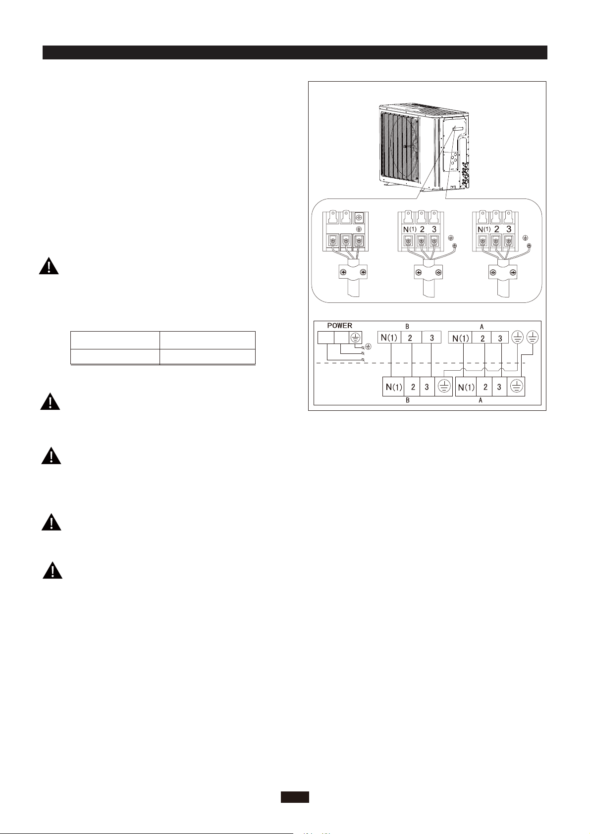
Wrong wire connection may cause malfunction of
some electric components.After fixing cable, ensure
that leads between connection to fixed point have
some space.
An all-pole disconnection switch having a contact
separation of at least 3mm in all pole should be
connected in fixed wiring.
2. Remove the cable clamp, connect the power connection
cable with the terminal at the row of connection and fix
the connection. The fitting line distributing must be
consistent with the indoor unit. terminal of line bank.
Wiring should meet that of indoor unit.
3. Fix power connection wire by wire clamp.
4. Ensure wire has been fixed well.
5. Install the handle.
unit (one screw).
The connection pipes and the connectiong wirings
of the unit A and unit B must be corresponding to
each other respective.
Note: the above figures are only intended to be a simple
diagram of the appliance and may not correspond to the
appearance of the units that have been purchased.
The appliance shall be installed in accordance with
national wiring regulations.
ELECTRICAL CONNECTIONS
1. Remove the handle at the right side plate of the outdoor
L1
L2
To the power supply
To unit B
Power cord
To unit A
connecting
cable
L1
L2
L1 L2
connecting
cable
Including an air switch with suitable capacity,
please note the following table. Air switch
should be included magnet buckle and heating
buckle function, it can protect the circuit-short
and overload. (Caution: please do not use the
fuse only for protect the circuit)
ISMO-1821
25A
Air switch capacityAir-conditioner
INSTALLING THE OUTDOOR UNIT INSTALLER
BLEEDING INSTALLER
5
Do not install the outdoor unit in pits or air vents
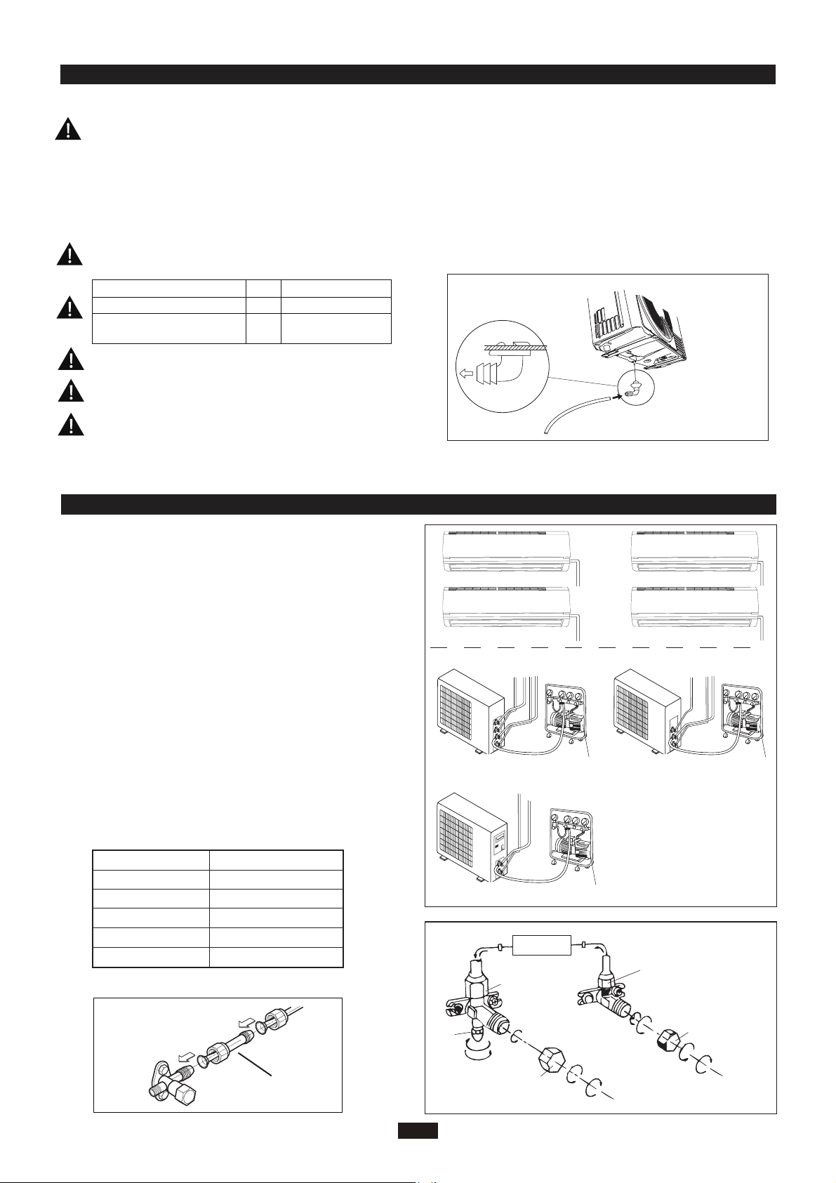
Installing the pipes
Use suitable connecting pipes and equipment for
the refrigerant R410A.
Vacuum pump
Humid air left inside the refrigerant circuit can cause com-
pressor malfunction. After having connected the indoor
and outdoor units, bleed the air and humidity from the
refrigerant circuit using a vacuum pump.
(1) Unscrew and remove the caps from the 2-way and 3-
way valves.
(2) Unscrew and remove the cap from the service valve.
(3) Connect the vacuum pump hose to the service valve.
(4) Operate the vacuum pump for 10-15 minutes until an
absolute vacuum of 10 mm Hg has been reached.
(5) With the vacuum pump still in operation, close the
low-pressure knob on the vacuum pump coupling.
Stop the vacuum pump.
(6) Open the 2-way valve by 1/4 turn and then close it
after 10 seconds. Check all the joints for leaks using
liquid soap or an electronic leak device.
(7) Turn the body of the 2-way and 3-way valves. Discon-
nect the vacuum pump hose.
(8) Replace and tighten all the caps on the valves.
Vacuum pump Vacuum pump
Location
Twisting moment (N.m)
35-40
60-65
45-50
70-75
Φ12
Φ19
Diameter (mm)
Φ9.52
Φ16
15-20Φ6
18K unit need to be installed the indoor unit
Caution: Installation Must be Performed in Accordance
with the NEC/CEC by Authorized Personnel Only.
conversion joint
18K MODE:
●
INDOOR
UNIT
Connect to the
indoor unit
Refrigerant fluid di
rection of fiow
3-way valve
2-way valve
inlet
(2)Turn
(8) Secure
(7)Turn to open fully
(2)Turn
(8) Secure
(6) Open by 1/4 turn
(7)Turn to open fully
(2)Turn
(8) Secure
V
alve cap
Valve cap
Service
The refrigerant pipes must not exceed the maximum
heights 5m(1821K).
Wrap all the refrigerant pipes and joints.
Tighten the connections using two wrenches wor-
king in opposite directions.
Use bolts to secure the unit to a flat, solid floor.
When mounting the unit on a wall or the roof, make
sure the support is firmly secured so that it cannot
move in the event of intense vibrations or a strong
wind.
Install the drain fitting and the drain hose
(for model with heat pump only)
Condensation is produced and flows from the out-
door unit when the appliance is operating in the
heating mode. In order not to disturb neighbours
and to respect the environment,install a drain fitting
and a drain hose to channel the condensate water.
Install the drain fitting and rubber washer on the
outdoor unit chassis and connect a drain hose to it
as shown in the figure.
Model(m) 1821x2
Max. connection pipe length
20
Max. connection pipe length
(Simple one indoor unit)
10
Use suitable instruments for the refrigerant R410A.
Do not use mineral oils to clean the unit.
Ensure that the recommende dspace is left around the appliance.
The installation must be done by trained and qualified service personnel with reliability according to this
manual.
Contact service center before installation to avoid the malfunction due to unprofessional installation.
When picking up and moving the units, you must be guidedby trained and qualified person.
Do not use any other refrigerant than R410A.
●
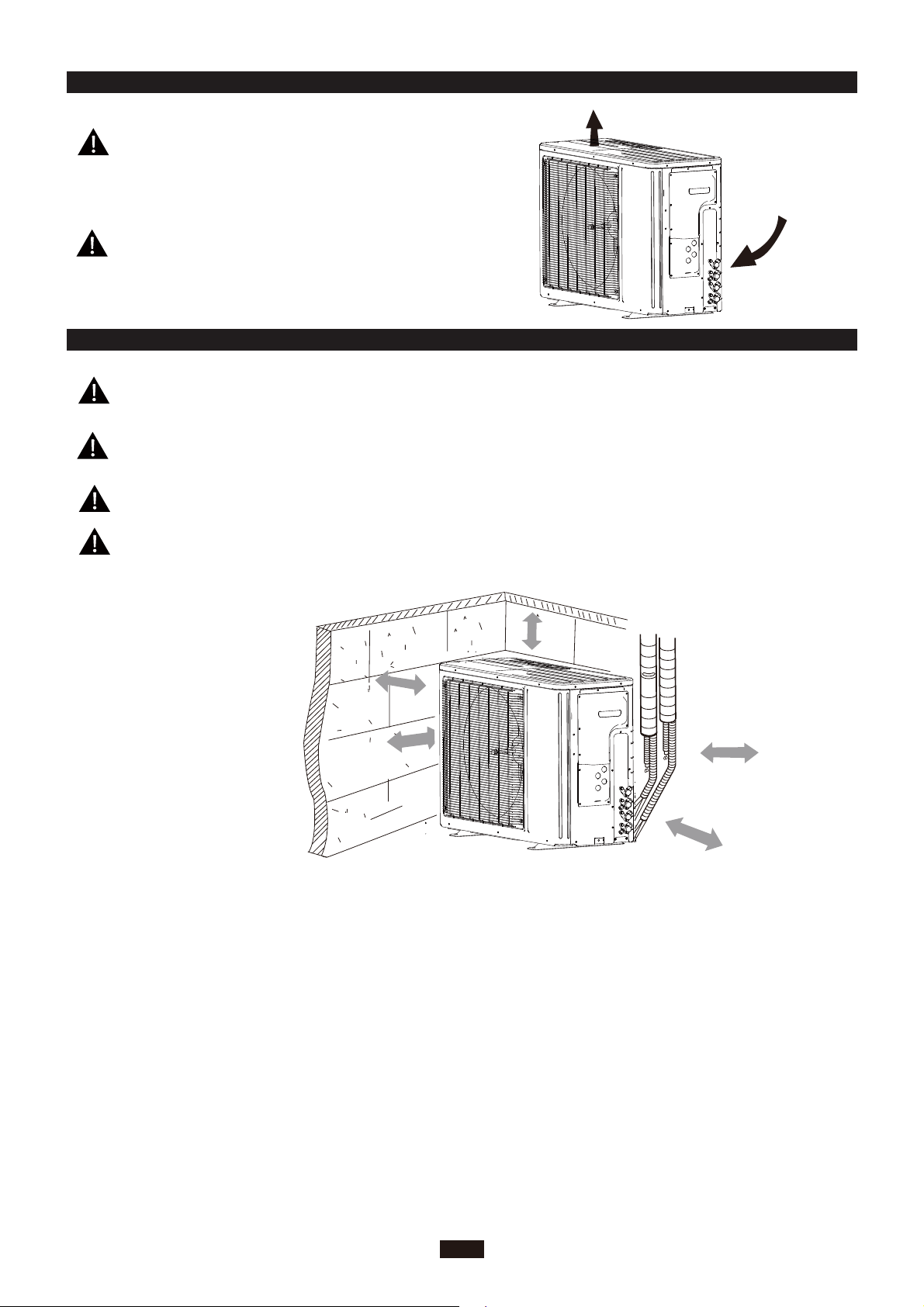
MAINTENANCE INSTALLER
INSTALLATION DIMENSION DIAGRAM INSTALLER
6
30cm
or above
Space to the cover
200cm
50cm
30cm
(Air inlet side)
or above
or above
Space to the wall
(Air outlet side)
or above
or more
Space to the cover
50c
m
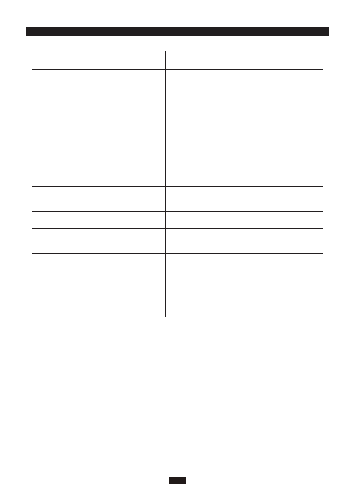
CHECK AFTER INSTALLATION INSTALLER
7
Check Items
Is the installation reliable?
Has the gas leakage been checked?
Is the thermal insulation of the unit
sufficient?
Is the drainage smooth?
Does the power supply voltage accord
with the rated voltage specified on the
nameplate?
Are the lines and pipelines correctly
installed?
Are the models of lines in conformity
with requirements?
Are there any obstacles near the air
inlet and outlet of the indoor and out-
door units?
Have the length of refrigerating pipe
and refrigerant charge amount been
recorded?
Has the unit been safely grounded?
Problems Owing to Improper Installation
The unit may drop, vibrate or make noises
May cause unsatisfactory cooling (heating)
effect
May cause condensation and water dropping
May cause condensation and water dropping
The unit may bread down or the components
may be burned out
The unit may bread down or the components
may be burned out
The unit may bread down or the components
may be burned out
The unit may bread down or the components
may be burned out
It is not easy to decide the charge amount
of refrigerant.
Risk of electrical leakage

CUSTOMER S
UPPORT
Before contacting customer support, please see the troubleshooting guide above.
Visit our website to contact us, find answers to Frequently Asked Questions, and for other
resources which may include an updated version of this user's guide.
WWW.IMPECCA.COM
If you wish to contact us by phone, please be sure to have your model number and serial
number ready and call us between 9:00am and 6:00pm ET, at +1 866-954-4440.
Keep tabs on Impecca's newest innovations & enter contests via our social network feeds:
www.facebook.com/Impecca/
www.instagram.com/impecca/
@impeccausa


© 2016 Impecca, a division of LT Inc., Wilkes Barre, PA.