Loading ...
Loading ...
Loading ...
ASSEMBLY INSTRUCTIONS
11
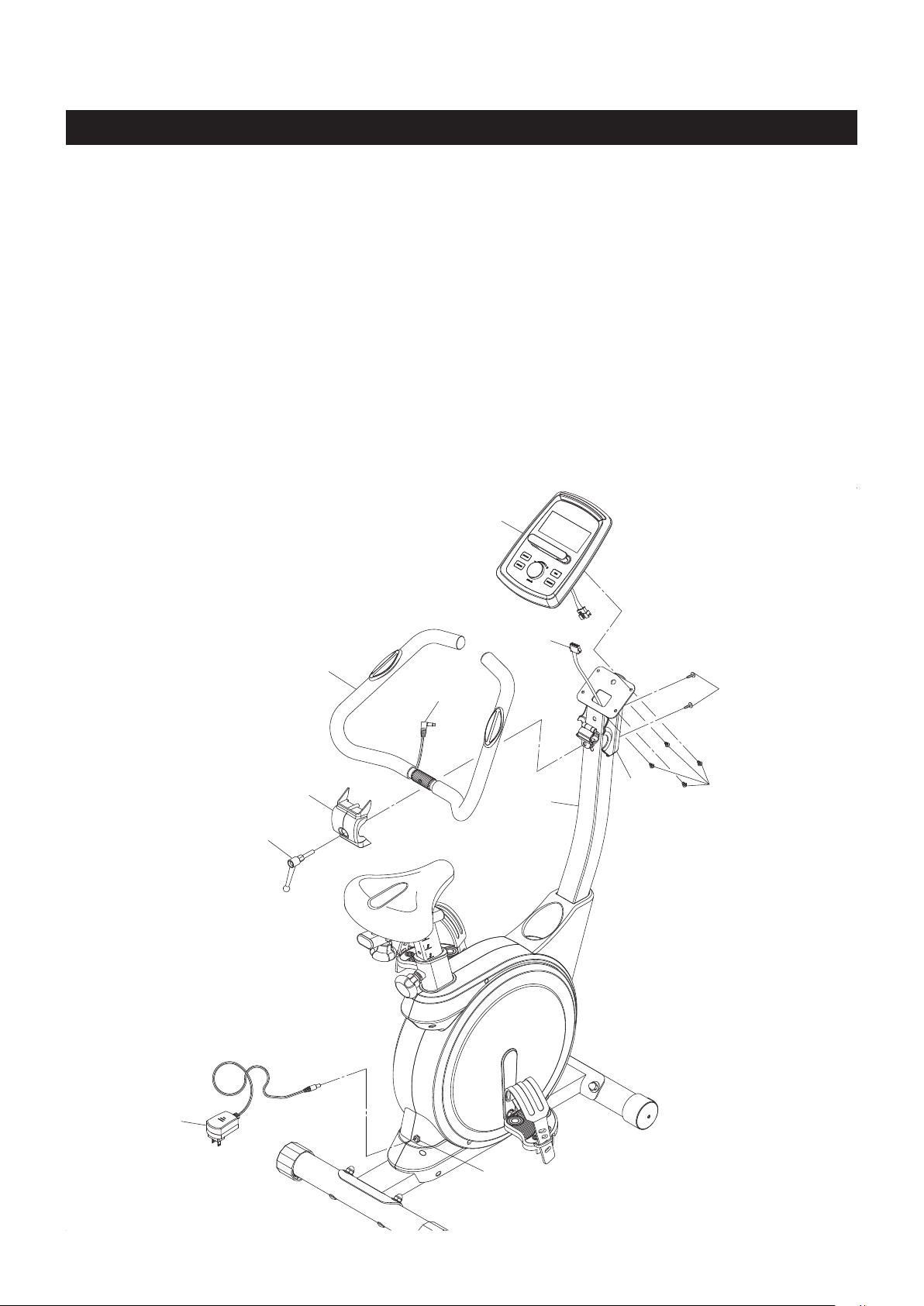
STEP 7
Refer to the illustration below. Place the HANDLEBAR(4) in the clip on the UPRIGHT(2), then secure with
the BACK HANDLEBAR COVER(10) and FIXING LEVER(11). Attach the BACK HANDLEBAR COVER(10)
and FRONT HANDLEBAR COVER(96) together with ROUND HEAD SCREWS(M4x20mm)(3).
STEP 8
Plug the EXTENSION CONTROL CABLE(76) into the connecting cable of the COMPUTER(1), and push
the excess wires back into the UPRIGHT(2). Attach the COMPUTER(1) to the plate on the UPRIGHT(2)
with ROUND HEAD SCREWS(M5x0.8x10mm)(75). Plug the PULSE SENSOR WIRE(95) into the back
of the COMPUTER(1).
NOTE: Be careful not to damage the wires when attaching the COMPUTER(1).
STEP 9
Plug the ADAPTER(85) into the SOCKET of the POWER WIRE(78) located on the back of the bike. Plug
the ADAPTER(85) into an electrical outlet.
75
3
96
2
4
10
11
1
76
78
85
95
Loading ...
Loading ...
Loading ...