MASF036-N1
MASF048-N1
MASF060-N1
USER’S MANUAL
AIR CURTAIN
Maxwell
Maxwell
THANKS FOR PURCHASING AIR CURTAIN, PLEASE READ IT CAREFULLY BEFORE USING
THANKS FOR PURCHASING AIR CURTAIN, PLEASE READ IT CAREFULLY BEFORE USING
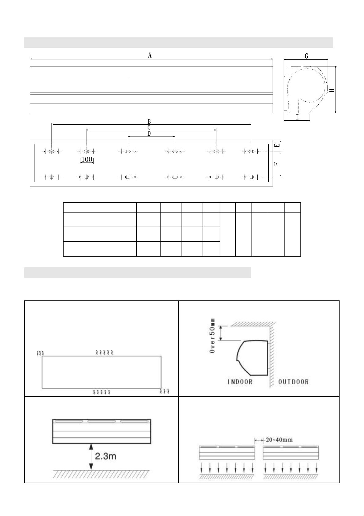
1、IDENTIFICATION & INSTALLATION DIMENSIONS
Units: in
MODEL A B C D E F G H I
MASF036-N1
35.4 27.4 --- --- 1.8 3.9 8.5 9.1 4.8
MASF048-N1
47.2 39 11.6 ---
MASF060-N1
59 50.6 19.8 ---
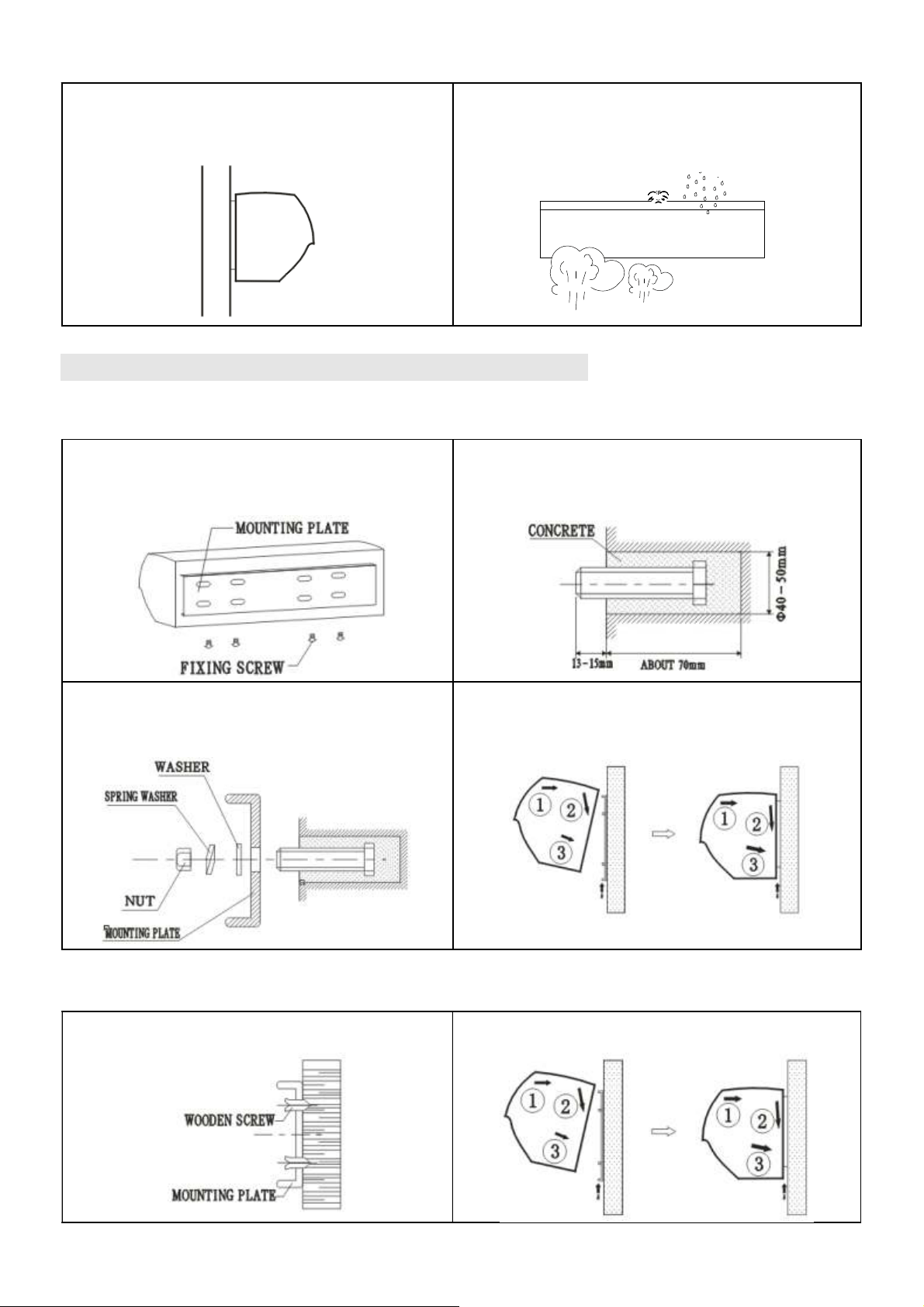
2、INSTALLATION CAUTION
Must follow the following asking when installing air curtain
:
2.1 Please install the unit in a sturdy place to avoid
the shaking and ensure its security (because it
maybe cause the wall becoming flexible or shaking
and noise.
2.2 Please install the unit inside the room.
2.3 Don’t install the unit too low, no less than 2.3
meter from the ground.
2.4 When the entrance is wider than the unit, it is
recommended to install two or more units in
parallel. In this case, provide 20-40mm gaps
between the units.
2.5 Don’t allow gaps between the unit and the
wall. When hanging it from the ceiling, using the
enclosed ceiling braskets.
2.6 Don’t install the unit in a place where it is
splashed by water, exposed to excessive steam,
explosive gas or corrosive gas.
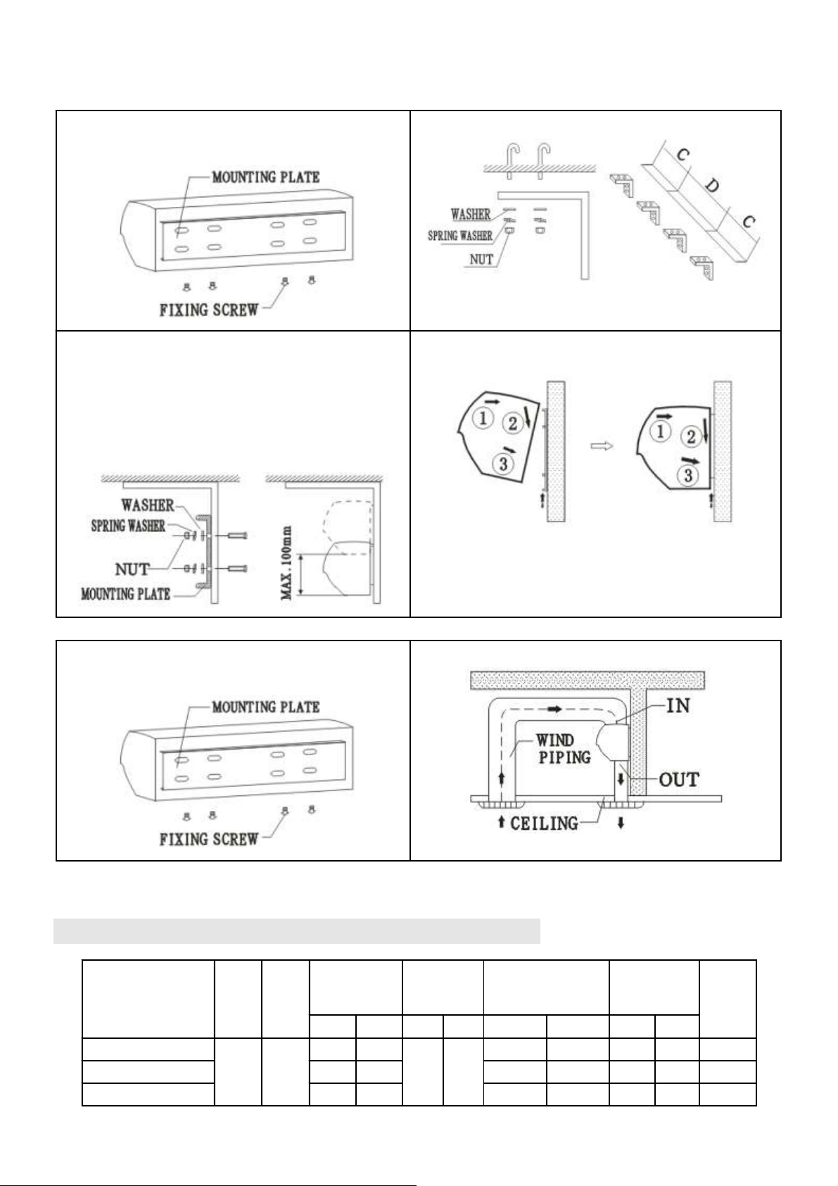
3、INSTALLATION
A Installing on the concrete wall:
3.1.1 Removed the mounting plate
Unclamping the fixed screws on the back of
main body to removed the mounting plate.
3.1.2 Fix the bolts in the proper position (Decide the
position with the mounting plate and pour cement
into the bolt holes.)
3.1.3 When the cement has freeze, fit the
mounting plate (use the washer and nut according
to the following)
3.1.4 Install the main body
Set the main body onto the upper end of the
mounting plate and clamp it as shown.
B、Installing on the wooden wall
3.2.1 Fix the mounting plate in the proper
positions with tapping screw.
3.2.2 Same as the step 3 of A
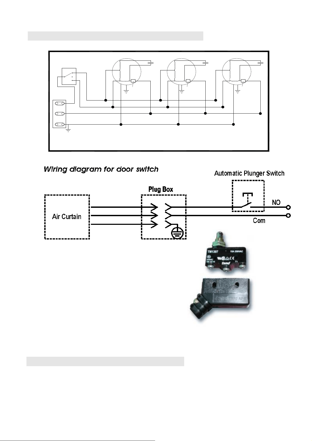
C、Hanging from the ceiling
3.3.1 Remove the mounting plate from main body
(Same as step3.1.1)
3.3.2 Fixing ceiling brackets as Fig.
3.3.3 Set the mounting plate on the ceiling
brackets and ensure safe & fixing (use the bolts
attached to the ceiling brackets as Fig. Using the
ceiling brackets to hang from the ceiling, the
position of mounting plate can be adjusted in the
limit of 100mm.
3.3.4 Do the same as step A to install the main body.
D、For above ceiling
3.4.1 Fix the air curtain as in the procedure for
installing on the concrete wall.
3.4.2 Then pipe as
below
Fig. Instructs.
4、TECHNICAL PARAMETER
MODEL
Volt.
(V~)
Freq
(Hz)
Max input
power
(W)
Max air
speed
(ft/s)
Air volume
(cfm)
Noise
(dB)
Net
weight
(LBS)
H L H L H L H L
MASF036-N1 110 60 230 200 52.5 42.7 647 530 52 49 28.7
MASF048-N1 290 260 883 707 53 50 34.2
MASF060-N1 380 350 1120 883 55 52 44
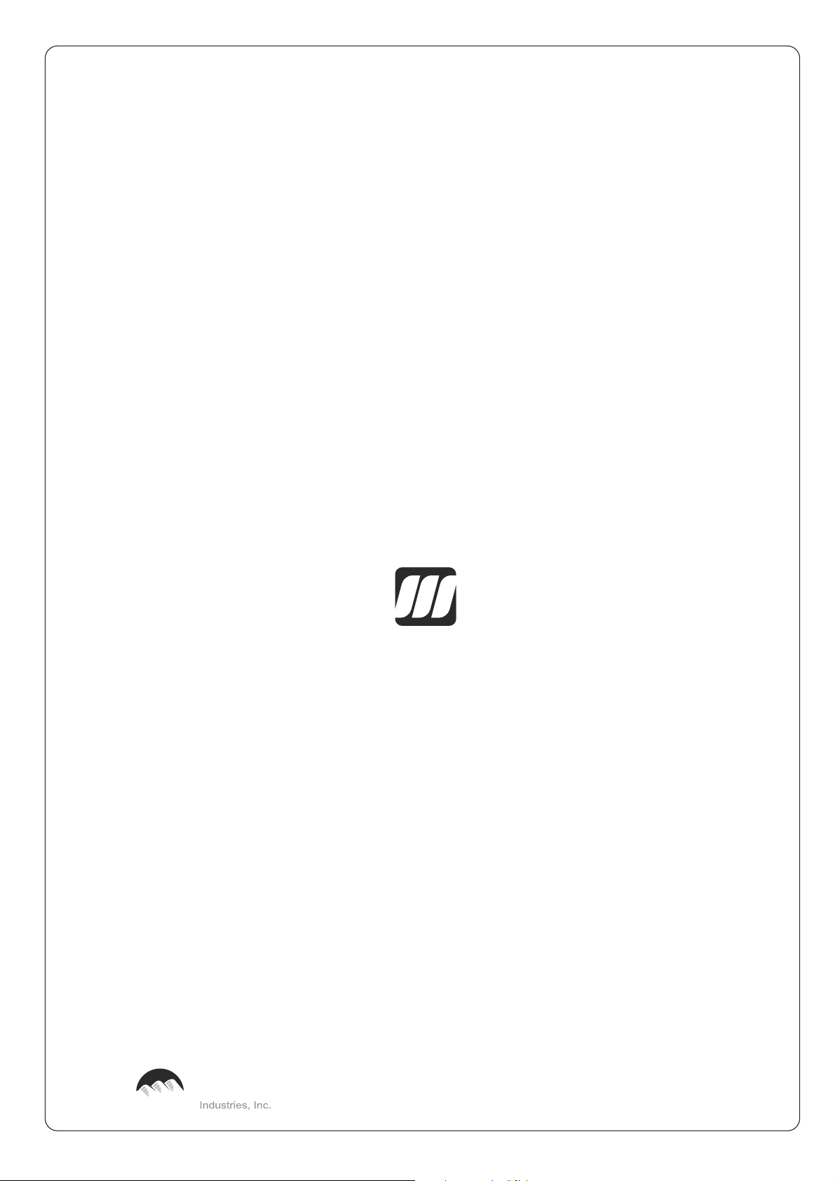
5、ELECTRIC WORK
GREY
BLACK
BLACK
BLACK
Hi
WHITE
GREEN
DOUBLE SPEED SWITCH WIRING DIACRAM
N
L
BLUE
BROWN
BLUE
THERMAL
CUT-OUT
BLUE
THERMAL
CUT-OUT
THERMAL
CUT-OUT
BLUE
K
OFF
Lo
RED
YELLOW
ORANGE
(YELLOW)
C
YELLOW
(YELLOW)
ORANGE
RED
C C
ORANGE
(YELLOW)
YELLOW
RED
Optional door switch & weather proof cover
Save energy & eliminate unnecessary air circulation
COM – common
NO – normally open
NC – normally close
6、OPERATION
6.1 Turn on the power switch
6.2 Select the best speed:High[H]、Low[L]
6.3 According to the installation place to adjust the wind direction parts to obtain the best effect.
7、CAUTIONS
a)、Use the unit at the rated voltage and frequency indicated on the nameplate.
b)、Disconnect power source before unit operation.
c)、Routing maintenance must be done every year.
d)、Never use petrol,benzese,thinner or any other such chemical for clearing the unit.
e)、Don’t allow water or anything enter the motor.
f) 、When power supply comes from socket, the plug must accord with IEC335-1.When the power cord is
connected with charging line directly, all polarity switches that the contact gap is 3mm at least must be installed
in the charging line.
Maxwell
Maxwell
Rockwell
Made by
Tel: (305)594-4972 Fax (305) 675-2212
www.rockwellus.com [email protected]
2190 NW 89 Place, Doral, FL 33172 USA