Loading ...
Loading ...
Loading ...
7
ASSEMBLY
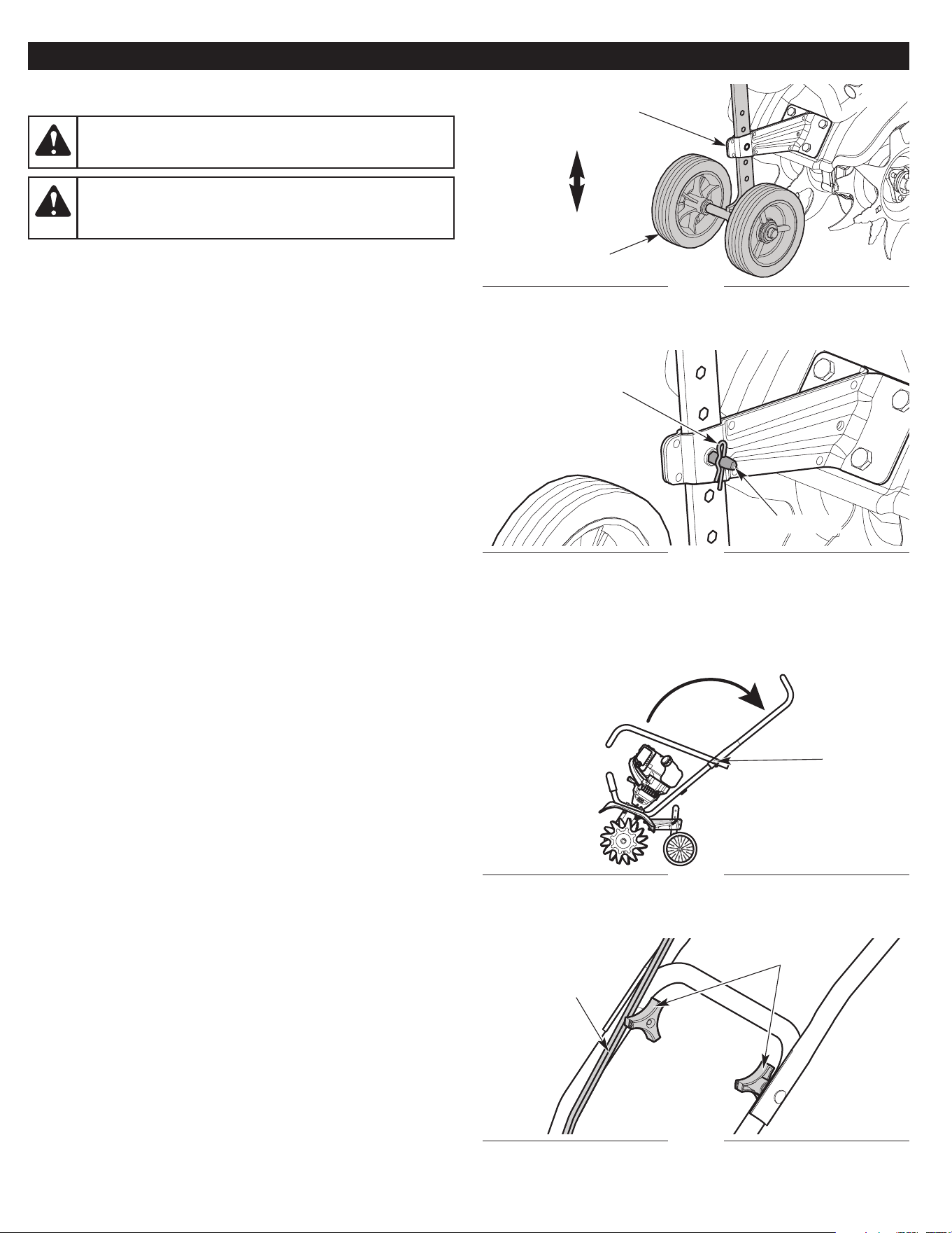
Fig. 2
Cotter Pin
INSTALLING AND ADJUSTING THE WHEEL ASSEMBLY
Installing the Wheel Assembly
1. Insert the wheel assembly into the wheel bracket. The "J" shape
of the wheel assembly should point away from the unit (Fig. 1).
2. Align the hole in the wheel bracket with the desired hole in the
wheel assembly (Fig. 1).
3. Insert the clevis pin through the aligned holes (Fig. 2).
4. Insert the cotter pin into the clevis pin (Fig. 2).
NOTE: It may be necessary to adjust the position of the wheel
assembly before using the unit.
Adjusting the Wheel Assembly
1. Remove the cotter pin from the clevis pin (Fig. 2).
2. Remove the clevis pin from the wheel bracket and wheel
assembly (Fig. 2).
3. Align the hole in the wheel bracket with the desired hole in the
wheel assembly (Fig. 1).
NOTE: Moving the wheel assembly down will raise the wheel height.
Moving the wheel assembly up will lower the wheel height.
4. Insert the clevis pin through the aligned holes (Fig. 2).
5. Insert the cotter pin into the clevis pin (Fig. 2).
Fig. 1
Wheel Assembly
Wheel Bracket
Clevis Pin
WARNING:
To avoid serious personal injury, the wheel
assembly must be installed before operating the unit.
WARNING:
To avoid injury from the tines, wear heavy
gloves and a long sleeve shirt when installing or adjusting
the wheel assembly.
Lower
Raise
Fig. 3
Fig. 4
Knobs
POSITIONING THE HANDLEBAR
1. Set the unit upright.
2. Loosen the knobs (Fig. 4).
3. Swing the handlebar up into the operating position (Fig. 3).
NOTE: Take care not to pinch the cables when positioning the
handlebar (Fig. 4).
4. Tighten the knobs securely.
NOTE: Do not over tighten the knobs.
5. Readjust the cables so they are smooth and tight against the
handlebar.
Knobs
Cables
Loading ...
Loading ...
Loading ...