Loading ...
Loading ...
Loading ...
ADJUSTMENTS TO COMPENSATE FOR WEAR
Even though the finest materials and precision workman-
ship have been used to minimize wear, after long use it
is reasonable to expect some wear. Adjustments have been
built into the Craftsman saw to reduce or eliminate this wear.
REMOVING RADIAL ARM SIDE PLAY
1. Set the radial arm at 0° index position, making sure
the arm latch handle is in the detent notch, and tighten
the arm lock handle. (See figure 25.)
2. Apply side force with one hand on radial arm in both
directions. If side play exists, an adjustment is required.
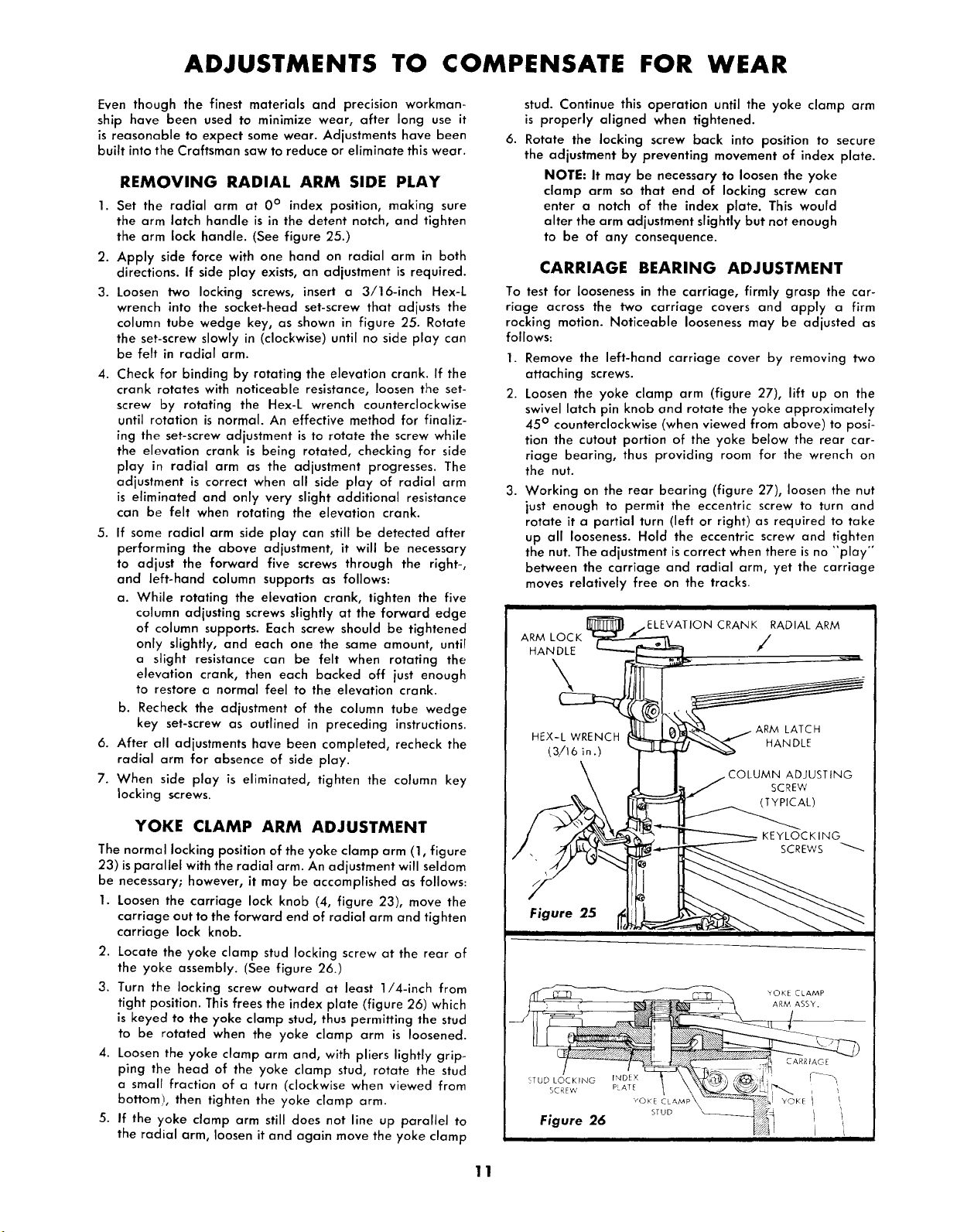
3. Loosen two locking screws, insert a 3/16-inch Hex-L
wrench into the socket-head set-screw that adjusts the
column tube wedge key, as shown in figure 25. Rotate
the set-screw slowly in (clockwise) until no side play can
be felt in radial arm.
4. Check for binding by rotating the elevation crank. If the
crank rotates with noticeable resistance, loosen the set-
screw by rotating the Hex-L wrench counterclockwise
until rotation is normal. An effective method for finaliz-
ing the set-screw adjustment is to rotate the screw while
the elevation crank is being rotated, checking for side
play in radial arm as the adjustment progresses. The
adjustment is correct when all side play of radial arm
is eliminated and only very slight additional resistance
can be felt when rotating the elevation crank.
5. If some radial arm side play can still be detected after
performing the above adjustment, it will be necessary
to adjust the forward five screws through the right-,
and left-hand column supports as follows:
a. While rotating the elevation crank, tighten the five
column adjusting screws slightly at the forward edge
of column supports. Each screw should be tightened
only slightly, and each one the same amount, until
a slight resistance can be felt when rotating the
elevation crank, then each backed off just enough
to restore a normal feel to the elevation crank.
b. Recheck the adjustment of the column tube wedge
key set-screw as outlined in preceding instructions.
6. After all adjustments have been completed, recheck the
radial arm for absence of side play.
7. When side play is eliminated, tighten the column key
locking screws.
YOKE CLAMP ARM ADJUSTMENT
The normal locking position of the yoke clamp arm (1, figure
23) is parallel with the radial arm. An adjustment will seldom
be necessary; however, it may be accomplished as follows:
1. Loosen the carriage lock knob (4, figure 23), move the
carriage out to the forward end of radial arm and tighten
carriage lock knob.
2. Locate the yoke clamp stud locking screw at the rear of
the yoke assembly. (See figure 26.)
3. Turn the locking screw outward at least 1/4-inch from
tight position. This frees the index plate (figure 26/which
is keyed to the yoke clamp stud, thus permitting the stud
to be rotated when the yoke clamp arm is loosened.
4. Loosen the yoke clamp arm and, with pliers lightly grip-
ping the head of the yoke clamp stud, rotate the stud
a small fraction of a turn (clockwise when viewed from
bottom!, then tighten the yoke clamp arm.
5. If the yoke clamp arm still does not line up parallel to
the radial arm, loosen it and again move the yoke clamp
stud. Continue this operation until the yoke clamp arm
is properly aligned when tightened.
6. Rotate the lacking screw back into position to secure
the adjustment by preventing movement of index plate.
NOTE: It may be necessary to loosen the yoke
clamp arm so that end of locking screw can
enter a notch of the index plate. This would
alter the arm adjustment slightly but not enough
to be of any consequence.
CARRIAGE BEARING ADJUSTMENT
To test for looseness in the carriage, firmly grasp the car-
riage across the two carriage covers and apply a firm
rocking motion. Noticeable looseness may be adjusted as
follows:
1. Remove the left-hand carriage cover by removing two
attaching screws.
2. Loosen the yoke clamp arm (figure 27), lift up on the
swivel latch pin knob and rotate the yoke approximately
45 ° counterclockwise (when viewed from above) to posi-
tion the cutout portion of the yoke below the rear car-
riage bearing, thus providing room for the wrench on
the nut.
3. Working on the rear bearing (figure 27), loosen the nut
just enough to permit the eccentric screw to turn and
rotate it a partial turn (left or right) as required to take
up all looseness. Hold the eccentric screw and tighten
the nut. The adjustment is correct when there is no "'play'"
between the carriage and radial arm, yet the carriage
moves relatively free on the tracks.
ARM ASS¥.
11
Loading ...
Loading ...
Loading ...