Loading ...
INSTALLATION INSTRUCTIONS
Made in China
3/4” (1.9 cm)
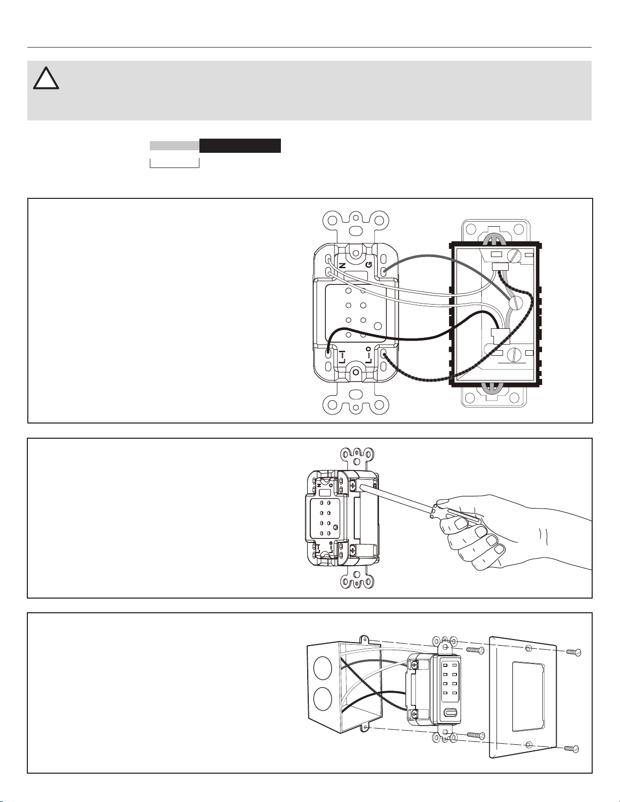
Straighten each wire and strip
3/4 in. (1.9 cm) of insulation
from each wire.
WALL
Hot wire
(Black)
Load wire
(Black/Red)
Neutral
(White)
Neutral
(White)
Ground
(Green)
Insert the ground (green) or bare wire(s) into the hole(s)
labeled G (near green screw).
Insert the two neutral (white) wires into the holes labeled
N (near silver screw).
Insert the hot (black) wire into the hole labeled L-I
(near brass screw).
Insert the load (black/red) wire into the hole labeled
L-O (near brass screw). The screw terminal accepts
14AWG-12AWG copper wire (12AWG maximum).
1.
2.
3.
4.
5. Tighten all screws firmly.
Carefully fold wires into wall box and mount Wall Switch
into wall box using mounting screws (CC), then attach a
standard decorator-style wall plate (not included) using
screws (DD).
Restore power by flipping the circuit breaker to the ON
position or re-installing the fuse to the circuit.
6.
7.
CC
CC
DD
DD
!
IMPORTANT: Installation should be made by a licensed electrician. This device is to be installed in a wall box measuring at least
3 in. x 2 in. x 2-1/2 in. (7.6 x 5 x 6.3 cm) (standard single gang electrical wall box) and wired in accordance with National Electrical Code.
WARNING: To avoid fire or electric shock, make sure power is OFF before beginning installation.
Loading ...
Loading ...