iNSTALLATiON AND SERVICE MUST BE PERFORMED BY A QUALiFiED iNSTALLER.
iMPORTANT:SAVEFORLOCALELECTRICALINSPECTOR'SUSE ,_, ,_.,_t_ /X_ "_
READ AND SAVE THESE iNSTRUCTiONS FOR FUTURE REFERENCE. i!_7/
If the information in this manual is not followed exactly, a _)_
fire or explosion may result causing property damage, personal injury
or death.
FOR YOUR SAFETY:
--Do not store or use gasoline or other flammable vapors and liquids
in the vicinity of this or any other appliance.
--WHAT TO DO IF YOU SMELL GAS:
• Do not try to light any appliance,
• Do not touch any electrical switch; do not use any phone in your
building,
• Immediately call your gas supplier from a neighbor's phone. Follow
the gas supplier's instructions,
• If you cannot reach your gas supplier, call the fire department.
--Installation and service must be performed by a qualified installer,
service agency or the gas supplier.
Refer to your serial plate for
applicable agency certification
Appliances Installed in the
state of Massachusetts:
This Appliance can only be installed
in the state of Massachusetts by a
Massachusetts licensed plumber or
gasfitter.
This appliance must be installed with
a three (3) foot / 36 in. long flexible
gas connector,
A"T" handle type manual gas valve
must be installed in the gas supply
line to this appliance.
_11_-_"
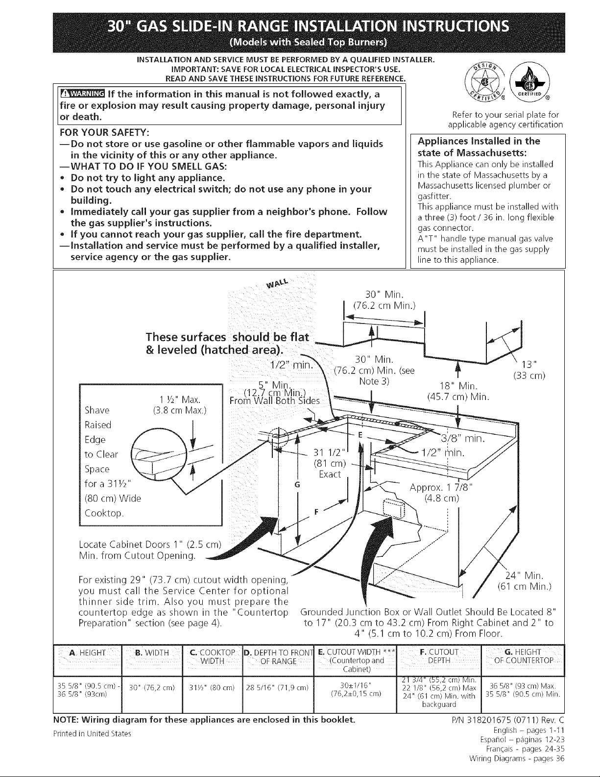
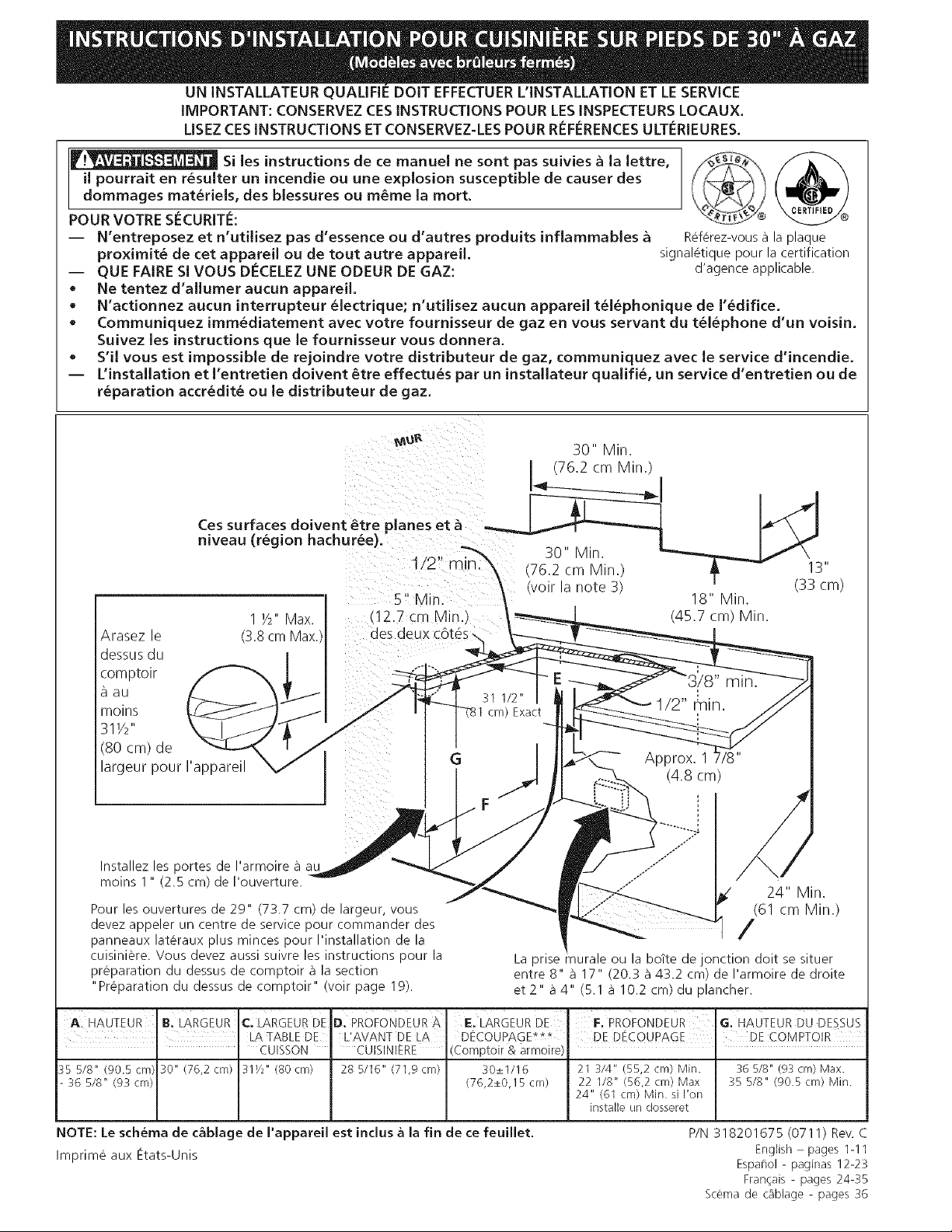
30" Min.
(76.2 cm Min.)
These surfaces should be flat _
& leveled (hatched area). _ _---_._._-_ i __ - _,_
_/o" _:_% 30" Min. _"_--_ \ 13"
.._ IIIin _ (76.2 cm) Min. (see _ - _ _-m_
5 Min. _ Note3) 18" Min.
E of qali otq{nslde 4577> in
Shave
Raised :--_z" _-'_J ___
Edge /'_! r __ _3i_
to Clear __ _ I_;.____ 311/2,, l _ 1/2" r_in. ////
_oPra;31V2'' _' /_ ,- Exact -h_.___ ._
, \_ G j _'-'-_-_ Approx. 1 7/8"
(80 cm)Wide _ j _:::_.. (4.8 cm)
Cooktop. / F . _.......jJ :: /
//
LOlcateCabinet Doors l,, (2.5 c_ J'__" _'_ .......
you must call the Service Center for optional
thinner side trim. Also you must prepare the I
countertop edge as shown in the "Countertop Grounded Junction Box or Wall Outlet Should Be Located 8"
Preparation" section (see page 4). to 17" (20.3 cm to 43.2 cm) From Right Cabinet and 2" to
4" (5.1 cm to 10.2 cm) From Floor.
A HEIGHT B. WIDTH C. COOKTOP D. DEPTH TO FRON] E. CUTOUTWIDTH *** F. CUTOUT G. HEIGHT
I WIDTH OF RANGE (Countertop and DEPTH, OF COUNTERTOB
• " " Cabinet) • '
21 3/4" (55,2 cm/ Min.
35 5/8" (90.5 cm) 30" (76,2 cm) 31Y2" (80 cm) 28 5/16" (71,9 cm) 30±1/16" 22 I/8" (56,2 cm) Max 36 5/8" (93 cm) Max.
36 5/8" (93cm) (76,2±0,15 cm) 24" (61 cm) Min. with 35 5/8" (90.5 cm) Min.
backguard
NOTE: Wiring diagram for these appliances are enclosed in this booklet.
Printed in United States
P/N 318201675 (0711) Rev. C
English - pages 1-11
Espat_ol - paginas 12-23
Fran_ais - pages 24-35
Wiring Diagrams - pages 36
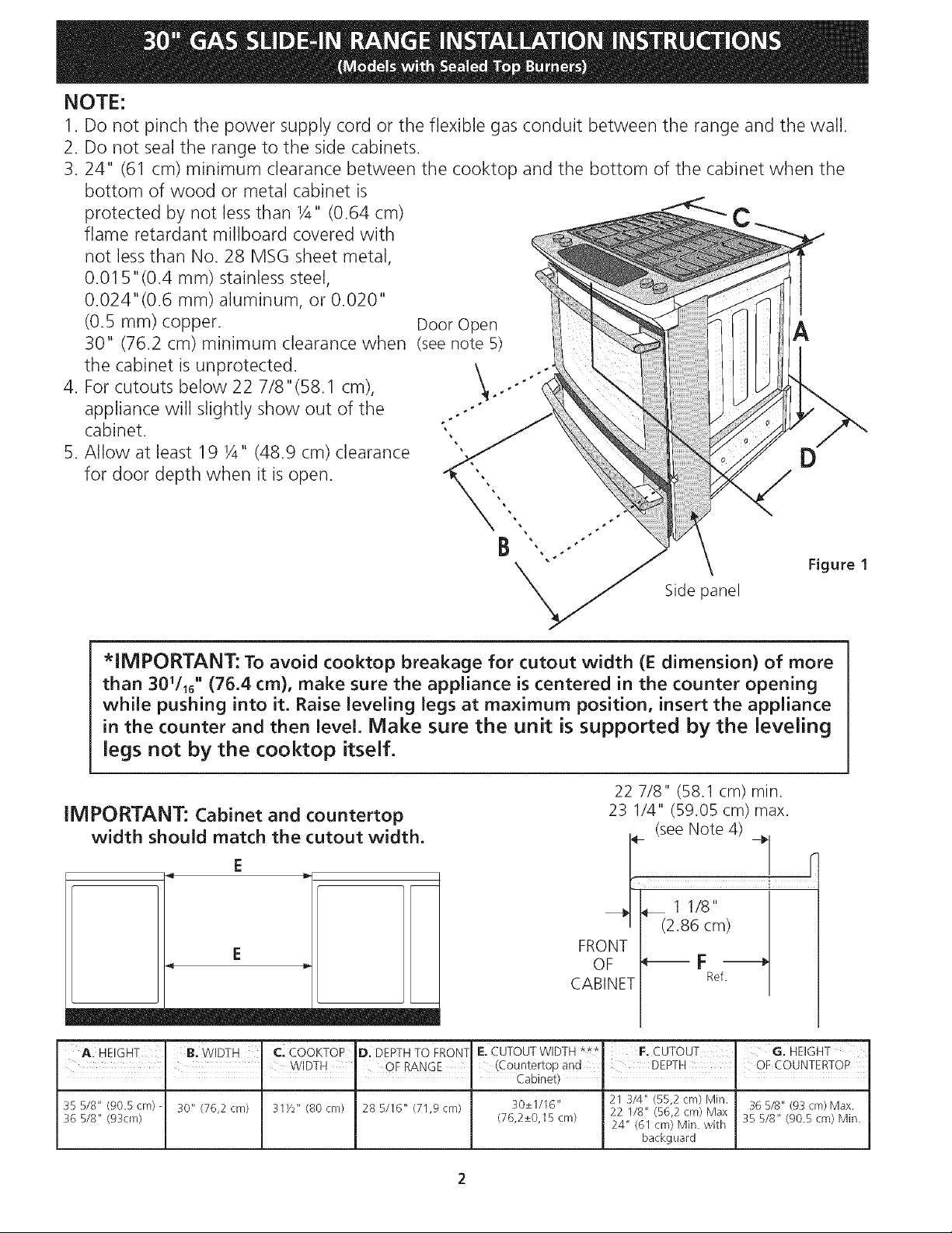
NOTE:
1. Do not pinch the power supply cord or the flexible gas conduit between the range and the wall.
2. Do not seal the range to the side cabinets.
3.24" (61 cm) minimum clearance between the cooktop and the bottom of the cabinet when the
bottom of wood or metal cabinet is
protected by not less than 1/4" (0.64 cm)
flame retardant millboard covered with
not less than No. 28 MSG sheet metal,
0.01 5"(0.4 ram) stainless steel,
0.024"(0.6 mm) aluminum, or 0.020"
(0.5 mm) copper. Door Open A
30" (76.2 cm) minimum clearance when (see note 5)
the cabinet is unprotected.
4. For cutouts below 22 7/8"(58.1 cm),
appliance will slightly show out of the
cabinet.
5. Allow at least 19 1/4" (48.9 cm) clearance
for door depth when it is open.
Side panel
Figure 1
*IMPORTANT: To avoid cooktop breakage for cutout width (E dimension) of more
than 30_/_6'' (76.4 cm), make sure the appliance is centered in the counter opening
while pushing into it. Raise leveling legs at maximum position, insert the appliance
in the counter and then level. Make sure the unit is supported by the leveling
legs not by the cooktop itself.
IMPORTANT: Cabinet and countertop
width should match the cutout width.
E
22 7/8" (58.1 cm) min.
23 1/4" (59.05 cm) max.
(see Note 4)
r
i
11/8"
_ (2.86 cm)
FRONT
OF _ F -_
CABINET Ref.
A. HEIGHT B. WIDTH C, COOKTOP DIDEPTHTOFRON- E. CUTOUTWlDTH***. F, CUTOUT GIHEIGHT
J J WIDTH OF RANGE (Countertop and DEPTH I OF COUNTERTOP
.... Cabinet) "
35 5/8" (90.5 cm) - 30" (76,2 cm) 31Y2" (80 cm) 28 5/16" (71,9 cm) 30+_I/16" 21 3/4" (55,2 cm) Min. 36 5/8" (93 cm) Max.
22 I/8" (56,2 cm) Max
36 5/8" (93cm) (76,2_+0,I 5 cm) 24" (61 cm) Min. with 35 5/8" (90.5 cm) Min.
backguard
Important Notes to the Installer
1. Read all instructions contained in these installation
instructions before installing range.
2. Remove all packing material from the oven
compartments before connecting the gas and
electrical supply to the range.
3. Observe all governing codes and ordinances.
4. Be sure to leave these instructions with the consumer.
5. Note: For operation at 2000 ft. elevations above see
level, appliance rating shall be reduced by 4 percent
for each additional 1000 ft.
range over carpeting unless you place an insulating pad
or sheet of ¼" (10,16 cm) thick plywood between the
range and carpeting,
• Make sure the wall coverings around the range
can withstand the heat generated by the range.
• Do not obstruct the flow of combustion air at the
oven vent nor around the base or beneath the
lower front panel of the range. Avoid touching the
vent openings or nearby surfaces as they may become
hot while the oven is in operation. This range requires
fresh air for proper burner combustion.
Important Note to the Consumer
Keep these instructions with your Use & Care Guide for
future reference.
IMPORTANT SAFETY
INSTRUCTIONS
Installation of this range must conform with local codes
or, in the absence of local codes, with the National Fuel
Gas Code ANSI Z223.1/NEPA .54-latest edition.
This range has been design certified by CSA
International. As with any appliance using gas and
generating heat, there are certain safety precautions
you should follow. You will find them in the Use and
Care Guide, read it carefully.
• Be sure your range is installed and grounded
properly by a qualified installer or service
technician.
• This range must be electrically grounded in
accordance with local codes or, in their absence,
with the National Electrical Code ANSI/NFPA No.
70--latest edition. See Grounding Instructions.
• Before installing the range in an area covered with
linoleum or any other synthetic floor covering,
make sure the floor covering can withstand heat at
least 90°F above room temperature without
shrinking, warping or discoloring. Do not install the
@
* All ranges
can tip.
Injury to
persons
could result.
* Install anti-
tip device
packed with
range.
_To
reduce the risk of
tipping of the range,
the range must be
secured by properly
installed anti-tip bracket
provided with the
range. To check if the
bracket is installed
properly, grasp the top
rear edge of the range
and carefully tilt it
forward to make sure
the range is anchored.
Never leave children alone or
unattended in the area where an appliance is in
use. As children grow, teach them the proper, safe use
of all appliances. Never leave the oven door open when
the range is unattended.
Stepping, leaning or sitting on the
doors or drawers of this range can result in serious
injuries and can also cause damage to the range.
• Do not store items of interest to children in the
cabinets above the range. Children could be
seriously burned climbing on the range to reach items.
• To eliminate the need to reach over the surface
burners, cabinet storage space above the burners
should be avoided.
• Adjust surface burner flame size so it does not
extend beyond the edge of the cooking utensil.
Excessive flame is hazardous.
• Do not use the oven as a storage space. This
creates a potentially hazardous situation.
• Never use your range for warming or heating the
room. Prolonged use of the range without adequate
ventilation can be dangerous.
• Do not store or use gasoline or other flammable
vapors and liquids near this or any other
appliance. Explosions or fires could result.
• In the event of an electrical power outage, the surface
burners can be lit manually. To light a surface burner,
hold a lit match to the burner head and slowly turn
the Surface Control knob to LITE. Use caution when
lighting surface burners manually.
• Reset all controls to the "off" position after using
a programmable timing operation.
FOR MODELS WITH SELF-CLEAN FEATURE:
• Remove oven racks, broiler pan, food and other
utensils before self-cleaning the oven. Wipe up
excess spillage. Follow the precleaning instructions in
the Use and Care Guide.
• Unlike the standard gas range, THIS COOKTOP IS
NOT REMOVABLE. Do not attempt to remove the
cooktop.
Cabinet Construction Provide an adequate Gas Supply
To eliminate the risk of cabinet burns and
fire, do not have cabinet storage space above the range.
If there is cabinet storage space above range, reduce
risk by installing a range hood that projects horizontally
a minimum of 5" (12.7 cm) beyond the bottom of the
cabinet.
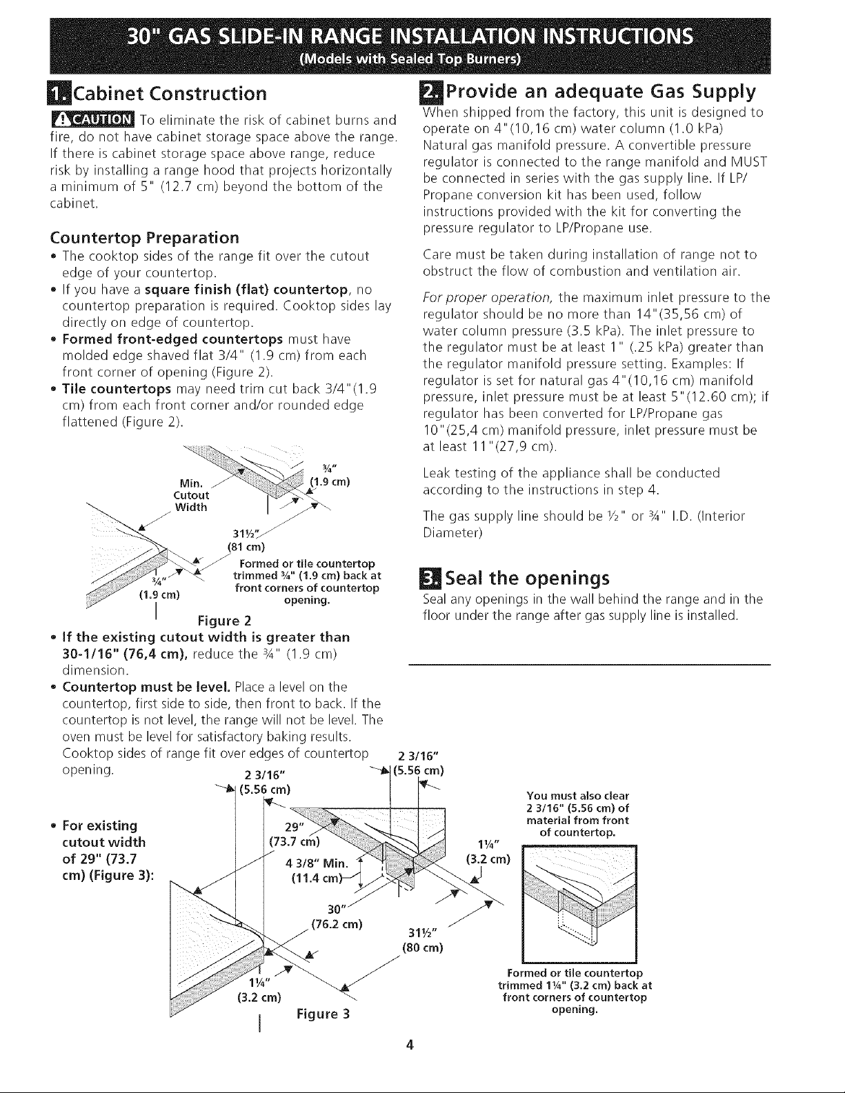
Countertop Preparation
The cooktop sides of the range fit over the cutout
edge of your countertop.
• If you have a square finish (flat) countertop, no
countertop preparation is required. Cooktop sides lay
directly on edge of countertop.
• Formed front-edged countertops must have
molded edge shaved flat 3/4" (1.9 cm) from each
front corner of opening (Figure 2).
• Tile countertops may need trim cut back 3/4"(1.9
cm) from each front corner and/or rounded edge
flattened (Figure 2).
When shipped from the factory, this unit is designed to
operate on 4"(10,16 cm) water column (1.0 kPa)
Natural gas manifold pressure. A convertible pressure
regulator is connected to the range manifold and MUST
be connected in series with the gas supply line. If LP/
Propane conversion kit has been used, follow
instructions provided with the kit for converting the
pressure regulator to LP/Propane use.
Care must be taken during installation of range not to
obstruct the flow of combustion and ventilation air.
For proper operation, the maximum inlet pressure to the
regulator should be no more than 14"(35,56 cm) of
water column pressure (3.5 kPa). The inlet pressure to
the regulator must be at least 1" (.25 kPa) greater than
the regulator manifold pressure setting. Examples: If
regulator is set for natural gas 4"(10,16 cm) manifold
pressure, inlet pressure must be at least 5"(12.60 cm); if
regulator has been converted for LP/Propane gas
10"(25,4 cm) manifold pressure, inlet pressure must be
at least 11 "(27,9 cm).
Leak testing of the appliance shall be conducted
according to the instructions in step 4.
31,/2,,_ _
(81cm)
Formed or tile countertop
trimmed %" (1,9 cm) back at
(1,9 cm} front corners of countertop
opening,
I Figure 2
• If the existing cutout width is greater than
30-1/16" (76,4 cm), reduce the 3A" (1.9 cm)
dimension.
• Countertop must be level. Place a level on the
countertop, first side to side, then front to back. If the
countertop is not level, the range will not be level. The
oven must be level for satisfactory baking results.
Cooktop sides of range fit over edges of countertop
opening.
• For existing
cutout width
of 29" (73.7
cm) (Figure 3):
The gas supply line should be Y2" or si" I.D. (Interior
Diameter)
[ Seal the openings
Seal any openings in the wall behind the range and in the
floor under the range after gas supply line is installed.
You must also clear
2 3116" (5.56 cm) of
material from front
of countertop,
Formed or tile counterto
trimmed 11A'' (3.2 cm) back at
front corners of countertop
opening,
Connect the range to the gas supply
Important: Remove all packing material and literature
from range before connecting gas and electrical supply.
To prevent leaks, put pipe joint sealant on all external
pipe threads.
Your regulator is in location shown below.
Do not
allow regulator to
rotate on pipe when
tightening fittings.
Figure 4
PRESSURE REGULATOR
LOCATION
Connection to Pressure Regulator
The regulator is already installed on the appliance.
Do not make the connection too tight.
The regulator is die cast. Overtightening may crack the
regulator resulting in a gas leak and possible fire or
explosion.
Manual GAS FLOW Pressure
Shutoff Flare _'_ Flare Regulator
Valve Union Union
Nipple Flexible
Off Connector Access
Cap
All connections must be wrench-tightened
Figure 5
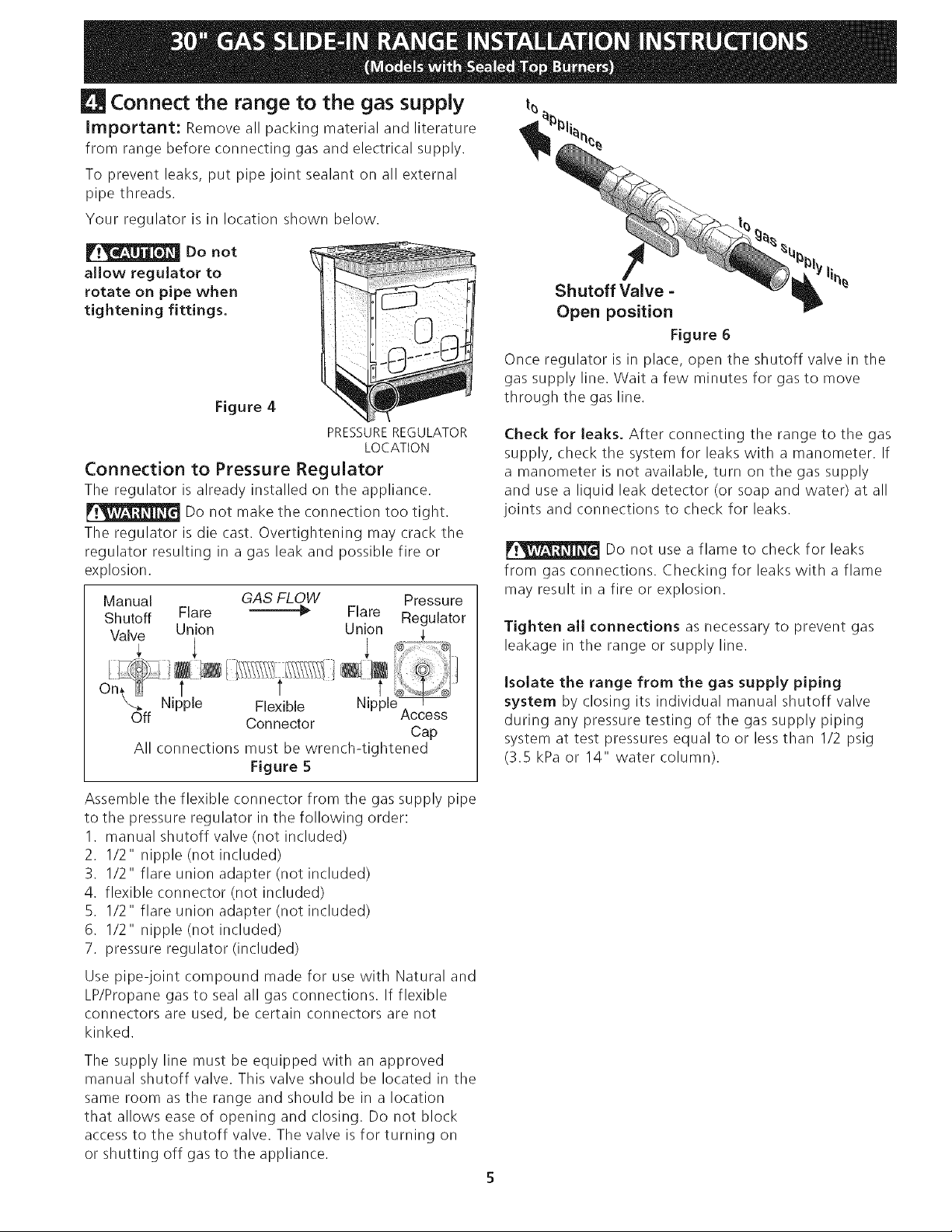
Shutoff Valve =
Open position
Figure 6
Once regulator is in place, open the shutoff valve in the
gas supply line. Wait a few minutes for gas to move
through the gas line.
Check for leaks. After connecting the range to the gas
supply, check the system for leaks with a manometer. If
a manometer is not available, turn on the gas supply
and use a liquid leak detector (or soap and water) at all
joints and connections to check for leaks.
Do not use a flame to check for leaks
from gas connections. Checking for leaks with a flame
may result in a fire or explosion.
Tighten all connections as necessary to prevent gas
leakage in the range or supply line.
Isolate the range from the gas supply piping
system by closing its individual manual shutoff valve
during any pressure testing of the gas supply piping
system at test pressures equal to or less than I/2 psig
(3.5 kPa or 14" water column).
Assemble the flexible connector from the gas supply pipe
to the pressure regulator in the following order:
1. manual shutoff valve (not included)
2. I/2" nipple (not included)
3. 1/2" flare union adapter (not included)
4. flexible connector (not included)
5. I/2" flare union adapter (not included)
6. 1/2" nipple (not included)
7. pressure regulator (included)
Use pipe-joint compound made for use with Natural and
LP/Propane gas to seal all gas connections. If flexible
connectors are used, be certain connectors are not
kinked.
The supply line must be equipped with an approved
manual shutoff valve. This valve should be located in the
same room as the range and should be in a location
that allows ease of opening and closing. Do not block
access to the shutoff valve. The valve is for turning on
or shutting off gas to the appliance.
[] LP/Propane Gas Conversion
Thisappliance can be used with Natural gas or LP/Propane
gas. It is shipped from the factory for use with natural gas.
If you wish to convert your range for use with LP/
Propane gas, use the supplied fixed orifices located in a
bag containing the literature marked "FOR LP/PROPANE
GAS CONVERSION." Follow the instructions packaged
with the orifices for surface, oven and broil burners
conversion.
The conversion must be performed by a qualified service
technician in accordance with the manufacturer's
instructions and all local codes and requirements.
Failure to follow these instructions could result in
serious injury or property damage. The qualified agency
performing this work assumes responsibility for the
conversion.
Failure to make the appropriate
conversion can result in serious personal injury and
property damage.
Electrical Requirements
120 volt, 60 Hertz, properly grounded dedicated circuit
protected by a 15 amp circuit breaker or time delay
fuse.
Note: Not recommended to be installed with a Ground
Fault Interrupt (GFI).
Do not use an extension cord with this range.
Grounding Instructions
IMPORTANT Please read carefully.
For personal safety, this appliance must be
properly grounded.
The power cord of this appliance is equipped with a 3-
prong (grounding) plug which mates with a standard 3-
prong grounding wall receptacle (see Figure 7) to
minimize the possibility of electric shock hazard from
the appliance.
The wall receptacle and circuit should be checked by a
qualified electrician to make sure the receptacle is
properly grounded.
Where a standard 2-prong wall receptacle is installed, it
is the personal responsibility and obligation of the
consumer to have it replaced by a properly grounded 3-
prong wall receptacle.
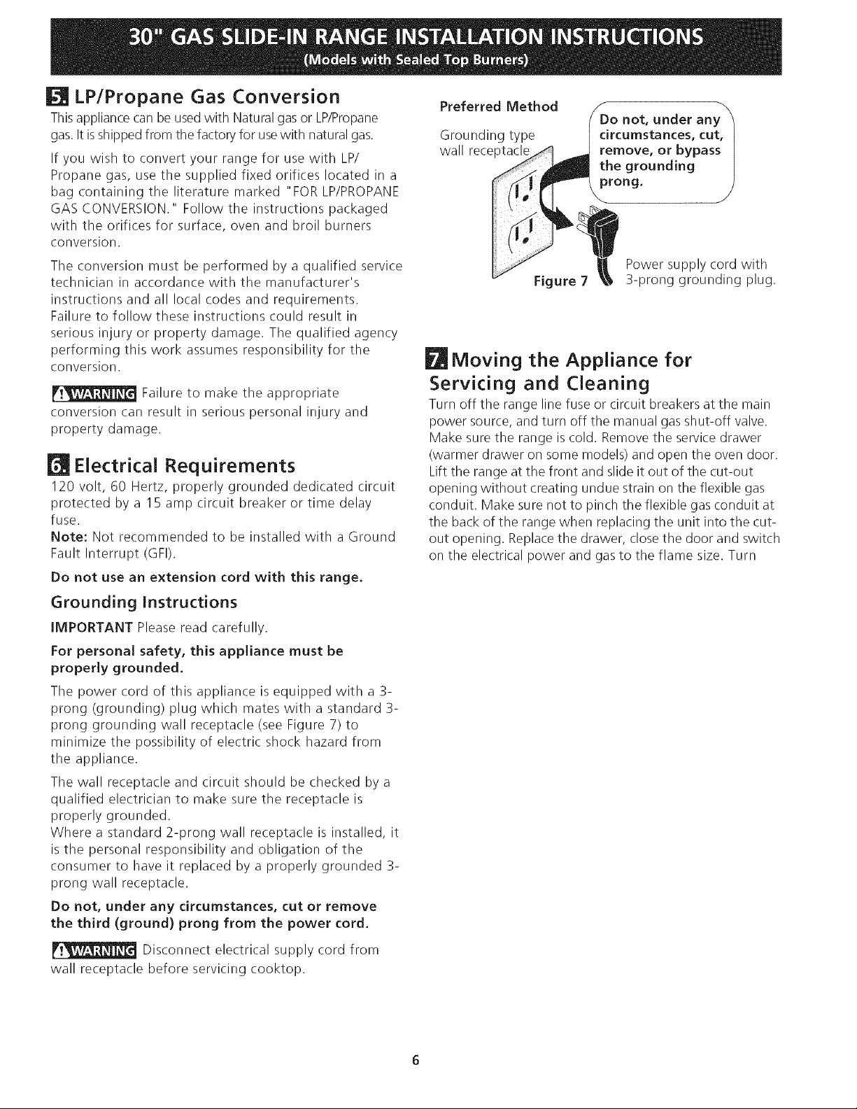
Do not, under any circumstances, cut or remove
the third (ground) prong from the power cord.
Disconnect electrical supply cord from
wall receptacle before servicing cooktop.
Preferred Method
Grounding type
wall receptacl_
Do not, under any
circumstances, cut,
remove, or bypass
the grounding
prong.
Figure 7
Power supply cord with
3-prong grounding plug.
Moving the Appliance for
Servicing and Cleaning
Turn off the range line fuse or circuit breakers at the main
power source, and turn off the manual gas shut-off valve.
Make sure the range is cold. Remove the service drawer
(warmer drawer on some models) and open the oven door.
Lift the range at the front and slide it out of the cut-out
opening without creating undue strain on the flexible gas
conduit. Make sure not to pinch the flexible gas conduit at
the back of the range when replacing the unit into the cut-
out opening. Replace the drawer, close the door and switch
on the electrical power and gas to the flame size. Turn
Range Installation
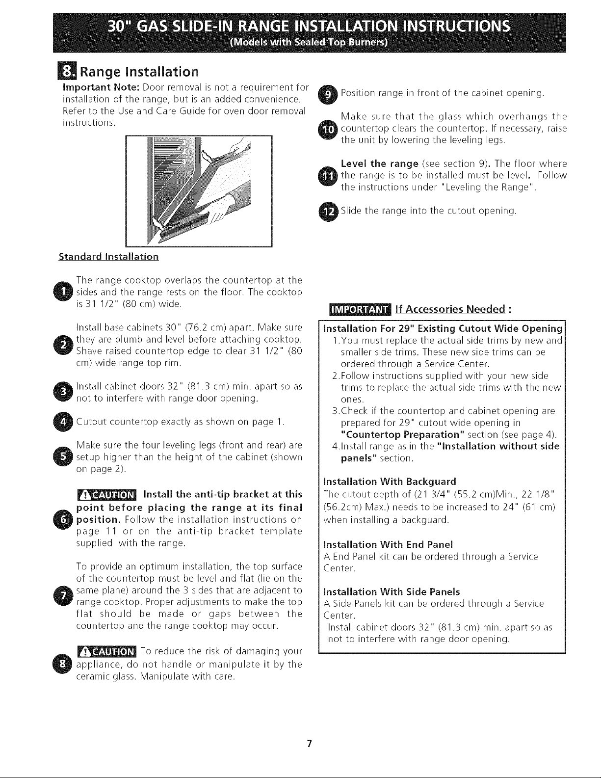
Important Note: Door removal is not a requirement for
installation of the range, but is an added convenience.
Refer to the Use and Care Guide for oven door removal
instructions.
Position range in front of the cabinet opening.
Make sure that the glass which overhangs the
countertop clears the countertop. If necessary, raise
the unit by lowering the leveling legs.
Level the range (see section 9). The floor where
the range is to be installed must be level. Follow
the instructions under "Leveling the Range".
Slide the range into the cutout opening.
Standard Installation
The range cooktop overlaps the countertop at the
I sides and the range rests on the floor. The cooktop
is 31 I/2" (80 cm) wide.
Install base cabinets 30" (762 cm) apart. Make sure
O they are plumb and level before attaching cooktop.
Shave raised countertop edge to clear 31 1/2" (80
cm) wide range top rim.
Install cabinet doors 32" (81.3 cm) rain. apart so as
not to interfere with range door opening.
bCutout countertop exactly as shown on page I.
Make sure the four leveling legs (front and rear) are
_setup higher than the height of the cabinet (shown
on page 2).
Install the anti-tip bracket at this
point before placing the range at its final
_position. Follow the installation instructions on
page 11 or on the anti-tip bracket template
supplied with the range.
To provide an optimum installation, the top surface
of the countertop must be level and flat (lie on the
same plane) around the 3 sides that are adjacent to
range cooktop. Proper adjustments to make the top
flat should be made or gaps between the
countertop and the range cooktop may occur.
To reduce the risk of damaging your
appliance, do not handle or manipulate it by the
ceramic glass. Manipulate with care.
If Accessories Needed :
Installation For 29" Existing Cutout Wide Opening
1.You must replace the actual side trims by new and
smaller side trims. These new side trims can be
ordered through a Service Center.
2.Follow instructions supplied with your new side
trims to replace the actual side trims with the new
ones.
3.Check if the countertop and cabinet opening are
prepared for 29" cutout wide opening in
"Countertop Preparation" section (see page 4).
4.Install range as in the "Installation without side
panels" section.
Installation With Backguard
The cutout depth of (21 3/4" (55.2 cm)Min., 22 I/8"
(56.2cm) Max.) needs to be increased to 24" (61 cm)
when installing a backguard.
Installation With End Panel
A End Panel kit can be ordered through a Service
Center.
Installation With Side Panels
A Side Panels kit can be ordered through a Service
Center.
Install cabinet doors 32" (81.3 cm) rain. apart so as
not to interfere with range door opening.
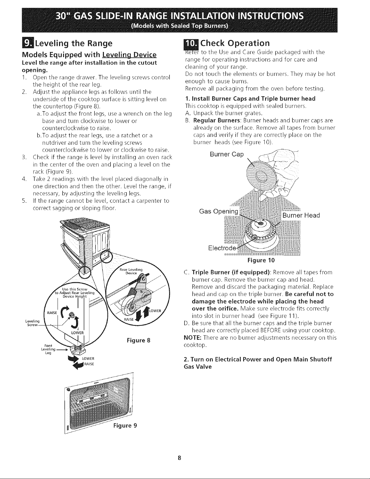
Leveling the Range
ModeJs Equipped with LeveJing Device
LeveJ the range after installation in the cutout
opening.
1. Open the range drawer. The leveling screws control
the height of the rear leg.
2. Adjust the appliance legs as follows until the
underside of the cooktop surface is sitting level on
the countertop (Figure 8).
a.To adjust the front legs, use a wrench on the leg
base and turn clockwise to lower or
counterclockwise to raise.
b.To adjust the rear legs, use a ratchet or a
nutdriver and turn the leveling screws
counterclockwise to lower or clockwise to raise.
3. Check if the range is level by installing an oven rack
in the center of the oven and placing a level on the
rack (Figure 9).
4. Take 2 readings with the level placed diagonally in
one direction and then the other. Level the range, if
necessary, by adjusting the leveling legs.
5. If the range cannot be level, contact a carpenter to
correct sagging or sloping floor.
Check Operation
to the Use and Care Guide packaged with the
range for operating instructions and for care and
cleaning of your range.
Do not touch the elements or burners. They may be hot
enough to cause burns.
Remove all packaging from the oven before testing.
1. InstaJJ Burner Caps and TripJe burner head
This cooktop is equipped with sealed burners.
A. Unpack the burner grates.
B. ReguJar Burners: Burner heads and burner caps are
already on the surface. Remove all tapes from burner
caps and verify if they are correctly place on the
burner heads (see Figure 10).
Burner Cap
/
Gas Opening
Burner Head
Leveling
Font
Leveling
Leg
LOWER
RAISE
Figure 8
Figure 10
C. Triple Burner (if equipped): Remove all tapes from
burner cap. Remove the burner cap and head.
Remove and discard the packaging material. Replace
head and cap on the triple burner. Be careful not to
damage the electrode while placing the head
over the orifice. Make sure electrode fits correctly
into slot in burner head (see Figure11).
D. Be sure that all the burner caps and the triple burner
head are correctly placed BEFOREusing your cooktop.
NOTE: There are no burner adjustments necessary on this
cooktop.
2. Turn on Electrical Power and Open Main Shutoff
Gas Valve
Figure 9
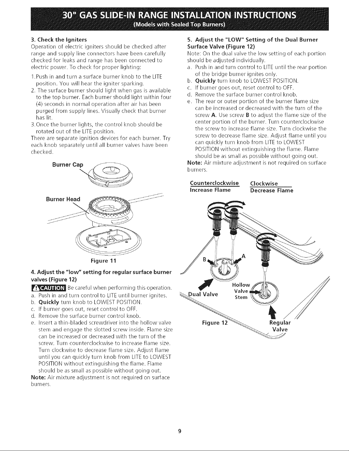
3,Checkthe Igniters
Operation of electric igniters should be checked after
range and supply line connectors have been carefully
checked for leaks and range has been connected to
electric power. To check for proper lighting:
1.Push in and turn a surface burner knob to the LITE
position. You will hear the igniter sparking.
2. The surface burner should light when gas is available
to the top burner. Each burner should light within four
(4) seconds in normal operation after air has been
purged from supply lines. Visually check that burner
has lit.
3.Once the burner lights, the control knob should be
rotated out of the LITEposition.
There are separate ignition devices for each burner. Try
each knob separately until all burner valves have been
checked.
Burner Ca_
Burner Head
Figure 11
4. Adjust the "low" setting for regular surface burner
valves (Figure 12)
Becareful when performing this operation.
a. Push in and turn control to LITEuntil burner ignites.
b. Quickly turn knob to LOWEST POSITION.
c. If burner goes out, reset control to OFF.
d. Remove the surface burner control knob.
e. Insert a thin-bladed screwdriver into the hollow valve
stem and engage the slotted screw inside. Flame size
can be increased or decreased with the turn of the
screw. Turn counterclockwise to increase flame size.
Turn clockwise to decrease flame size. Adjust flame
until you can quickly turn knob from LITEto LOWEST
POSITIONwithout extinguishing the flame. Flame
should be as small as possible without going out.
Note: Air mixture adjustment is not required on surface
burners.
5. Adjust the "LOW" Setting of the Dual Burner
Surface Valve (Figure 12)
Note: On the dual valve the low setting of each portion
should be adjusted individually.
a. Push in and turn control to LITEuntil the rear portion
of the bridge burner ignites only.
b. Quickly turn knob to LOWESTPOSITION.
c. If burner goes out, reset control to OFF.
d. Remove the surface burner control knob.
e. The rear or outer portion of the burner flame size
can be increased or decreased with the turn of the
screw A. Use screw B to adjust the flame size of the
center portion of the burner. Turn counterclockwise
the screw to increase flame size. Turn clockwise the
screw to decrease flame size. Adjust flame until you
can quickly turn knob from LITE to LOWEST
POSITIONwithout extinguishing the flame. Flame
should be as small as possible without going out.
Note: Air mixture adjustment is not required on surface
burners.
CountercJockwise
increase FJame
Clockwise
Decrease Flame
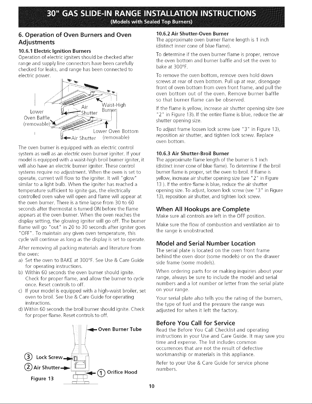
6. Operation of Oven Burners and Oven
Adjustments
10.6.1 Electric ignition Burners
Operation of electric igniters should be checked after
range and supply line connectors have been carefully
checked for leaks, and range has been connected to
electric power.
Lower
Oven Baffle
(removable
Air Waist-High
Shutter Burrler
_-
j_
Lower Oven Bottom
,Air Shutter (removable)
The oven burner is equipped with an electric control
system as well as an electric oven burner igniter. If your
model is equipped with a waist-high broil burner igniter, it
will also have an electric burner igniter. These control
systems require no adjustment. When the oven is set to
operate, current will flow to the igniter. It will "glow"
similar to a light bulb. When the igniter has reached a
temperature sufficient to ignite gas, the electrically
controlled oven valve will open and flame will appear at
the oven burner. There is a time lapse from 30 to 60
seconds after thermostat is turned ON before the flame
appears at the oven burner. When the oven reaches the
display setting, the glowing igniter will go off. The burner
flame will go "out" in 20 to 30 seconds after igniter goes
"OFF". To maintain any given oven temperature, this
cycle will continue as long as the display is set to operate.
After removing all packing materials and literature from
the oven:
a) Set the oven to BAKE at 300%. See Use & Care Guide
for operating instructions.
b) Within 60 seconds the oven burner should ignite.
Check for proper flame, and allow the burner to cycle
once. Reset controls to off.
c) If your model is equipped with a high-waist broiler, set
oven to broil. See Use & Care Guide for operating
instructions.
d) Within 60 seconds the broil burner should ignite. Check
for proper flame. Reset controls to off.
/_II-- Oven Burner Tube
@ Lock Screw_ _
@ Air Shutter.._ _
Figure 13 t_l.,, @ Orifice Hood
10.6.2 Air Shutter-Oven Burner
The approximate oven burner flame length is 1 inch
(distinct inner cone of blue flame).
To determine if the oven burner flame is proper, remove
the oven bottom and burner baffle and set the oven to
bake at 300%.
To remove the oven bottom, remove oven hold down
screws at rear of oven bottom. Pull up at rear, disengage
front of oven bottom from oven front frame, and pull the
oven bottom out of the oven. Remove burner baffle
so that burner flame can be observed.
If the flame is yellow, increase air shutter opening size (see
"2" in Figure 13). If the entire flame is blue, reduce the air
shutter opening size.
To adjust frame loosen lock screw (see "3" in Figure 13),
reposition air shutter, and tighten lock screw. Replace
oven bottom.
10.6.3 Air Shutter-Broil Burner
The approximate flame length of the burner is 1 inch
(distinct inner cone of blue flame). To determine if the broil
burner flame is proper, set the oven to broil. If flame is
yellow, increase air shutter opening size (see "2" in Figure
13 ). If the entire flame is blue, reduce the air shutter
opening size. To adjust, loosen lock screw (see "3" in Figure
13), reposition air shutter, and tighten lock screw.
When All Hookups are Complete
Make sure all controls are left in the OFFposition.
Make sure the flow of combustion and ventilation air to
the range is unobstructed.
Model and Serial Number Location
The serial plate is located on the oven front frame
behind the oven door (somemodel_ or on the drawer
side frame (some models).
When ordering parts for or making inquiries about your
range, always be sure to include the model and serial
numbers and a lot number or letter from the serial plate
on your range.
Your serial plate also tells you the rating of the burners,
the type of fuel and the pressure the range was
adjusted for when it left the factory.
Before You Call for Service
Read the Before You Call Checklist and operating
instructions in your Use and Care Guide. It may save you
time and expense. The list includes common
occurrences that are not the result of defective
workmanship or materials in this appliance.
Refer to your Use & Care Guide for service phone
numbers.
10
Anti-Tip Brackets installation
instructions
To reduce the risk of tipping of the range,
the range must be secured to the floor by properly
installed anti-tip bracket and screws packed with the
range. These parts are located in the oven. Failure to
install the anti-tip bracket will allow the range to tip over
if excessive weight is placed on an open door or if a child
climbs upon it. Serious injury might result from spilled hot
liquids or from the range itself.
Follow the instructions below to install the anti-tip
brackets.
If range is ever moved to a different location, the anti-
tip brackets must also be moved and installed with the
range.
Tools Required:
Adjustable Wrench
Ratchet
Drill & 1/8"(0,32 cm) bit
5/16" (0,8 cm) Nutdriver
Level
The anti-tip bracket attaches to the floor at the back of
the range to prevent range from tipping. When fastening
bracket to the floor, be sure that screws do not penetrate
electrical wiring or plumbing. The screws provided will
work in either wood or concrete.
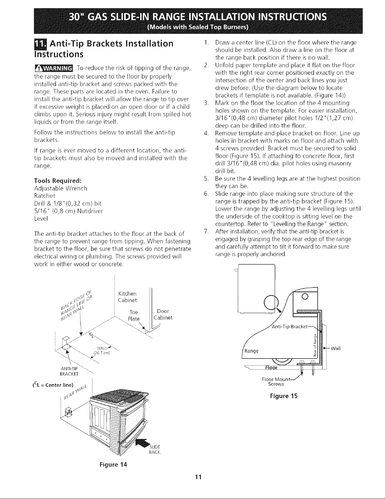
1. Draw a center line (CL) on the floor where the range
should be installed. Also draw a line on the floor at
the range back position if there is no wall.
2. Unfold paper template and place it flat on the floor
with the right rear corner positioned exactly on the
intersection of the center and back lines you just
drew before. (Use the diagram below to locate
brackets if template is not available. (Figure 14))
3. Mark on the floor the location of the 4 mounting
holes shown on the template. For easier installation,
3/16"(0,48 cm) diameter pilot holes 1/2"(1,27 cm)
deep can be drilled into the floor.
4. Remove template and place bracket on floor. Line up
holes in bracket with marks on floor and attach with
4 screws provided. Bracket must be secured to solid
floor (Figure 15). If attaching to concrete floor, first
drill 3/16"(0,48 cm) dia. pilot holes using masonry
drill bit.
5. Be sure the 4 levelling legs are at the highest position
they can be.
6. Slide range into place making sure structure of the
range is trapped by the anti-tip bracket (Figure 15).
Lower the range by adjusting the 4 levelling legs until
the underside of the cooktop is sitting level on the
countertop. Refer to "Levelling the Range" section.
7. After installation, verify that the anti-tip bracket is
engaged by grasping the top rear edge of the range
and carefully attempt to tilt it forward to make sure
range is properly anchored.
Range
Screws
Figure 15
-Watt
Figure 14
BACK
11
LAINSTALACIONY ELSERVIClO DEBEN SEREFECTUADOSPOR UN INSTALADOR CALIFICADO. !_--_,x\ /._.\
IMPORTANTE:GUARDEESTASINSTRUCClONESPARA USO DELINSPECTORLOCALDE ELECTRIaDAD.
LEAY GUARDE ESTASINSTRUCCIONESPARA REFERENCIAFUTURA. '_/
II_ Si la informaci6n contenida eneste manual no es seguida
exactamente, puede ocurrir un incendio o explosi6n causando daffos
materiales, lesi6n personal o la muerte.
PARASUSEGURIDAD:
-- No almacene ni utilice gasolina u otros vapores y liquidos inflamables en la proximidad
de 6steo de cualquier otro artefacto.
-- QUEDEBEHACERSl PERClBEOLORA GAS:
* No trate de encender ningun artefacto.
* No toque ningun interruptorel6ctrico; no use ningun tel_fono en su edificio.
* Llame a su proveedor de gas desde el tel6fono de un vecino. Siga las instrucciones del
proveedordegas.
* Sino logra comunicarse con su proveedor de gas,llame al departamento de bomberos.
-- La instalaci6n y el servicio de mantenimiento deben ser efectuadospor un instalador
calificado, la agencia de servicio o el proveedor de gas.
Aparatos Instalados en el
estado de Massachusetts;
Este Aparato s61o puede ser
instalado en el estado de
Massachusetts por un plomero
o ajustador de gas licenciado
de Massachusett.
Este aparato se debt instalar
con un largo conector flexible
de gas de tres (3) pies/36
pulgadas.
Una wilvula manual de gas de
tipo manija de forma de "T" se
debt instalar en la linea del
suministro de gas de este
aparato.
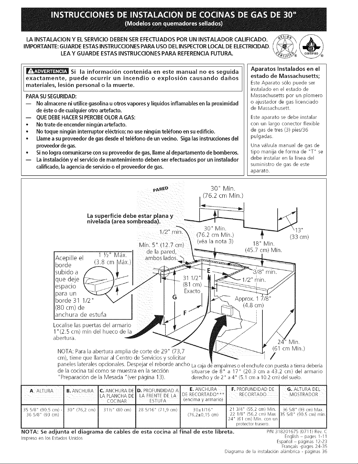
D u ,
pp,e._. 30 Mm.
(76.2 cm Mfn.)
nivelada (area sombreada)_ "_-_-a_-'-'v I _ _ _I
..... 7"_ 30" Min. _'-"_'-_ Jf \ 13"
Min. 5" (12.7 cm) \ _veala nota _) 18" Min.
de la pared, ' __ (45.7 cm) Min.
Acep e e Y' " ambos lados \ _--_,_T
borde (3.8 cm Vl_ix.) ...... __z,___
_ - d-___ 31 I/2 I
que deje __ __ 31 I/2" _ 1/2" _nin. _
es"acio _ /-_J'_ / ' (81 cm)_ ___
H
borde 31 1/2" V _ ._.y_._ Approx. 1 7/8
(80 cm) de _ j _ (4.8 cm) ...
anchura de estufa _, / F " //__ i 7
Localiselaspuertasdelarmario P" ,r_/ _ j__ .....P / /
1"(2.5 cm) min del hueco de la _ /- / _ ...........
__ _'_ _" 24" Min.
, _ (61 cm_ '_ -- Min )
NOTA: Parala abertura arnplia de corte de 29" (73,7 _.""" _/ _ "
cm), tiene que Ilamar al Centro de Serviciosy solicitar ,_ ,_ , , _ /
paneles laterales opcionales. Despejar el reborde ancho Lacajadeempalmeso el enchufecon puestaa tierra deberia
de la cocina tal como se muestra en la secciOn situarse de 8" a 17" (20.3 cm a 43.2 cm) del armario
"PreparaciOn de la Mesada "(ver pagina 13). derechoy de2" a 4" (5.1 cm a 10.2 cm) del suelo.
A. ALTURA B. ANCHURA C[ ANCHURA DE D. PROFUNDIDADA
LA PLANCHA DE LA FRENTE DE LA
• COCINAR ESTUFA
35 5/8" (90.5 cm) - 30" (76,2 cm) 31Y2" (80 cm) 28 5/16" (71,9 cm)
36 518" (93 cm)
E. ANCHURA
DE RECORTADO***
(encima y armario)
30+_I/16"
(76,2_+0,15 cm)
F. PROFUNDIDADDE . G. ALTURADEL
RECORTADO MOSTRADOR
21 3/4" (55,2 cm) Min. 36 5/8" (93 cm) Max.
22 1/8" (56,2 cm) Max 35 5/8" (90.5 cm) rain.
J24" (61 cm} Min. con un
protector trasero.
NOTA: Se adjunta el diagrama de cables de esta cocina al final de este libreta. P/N 318201675 (0711) Rev. C
Impreso en los Estados Unidos English - pages 1-11
Espanol - p_iginas 12-23
Fran_ais -pages 24-35
Diagrama de la instalaciOn aBmbrica - p_iginas 36
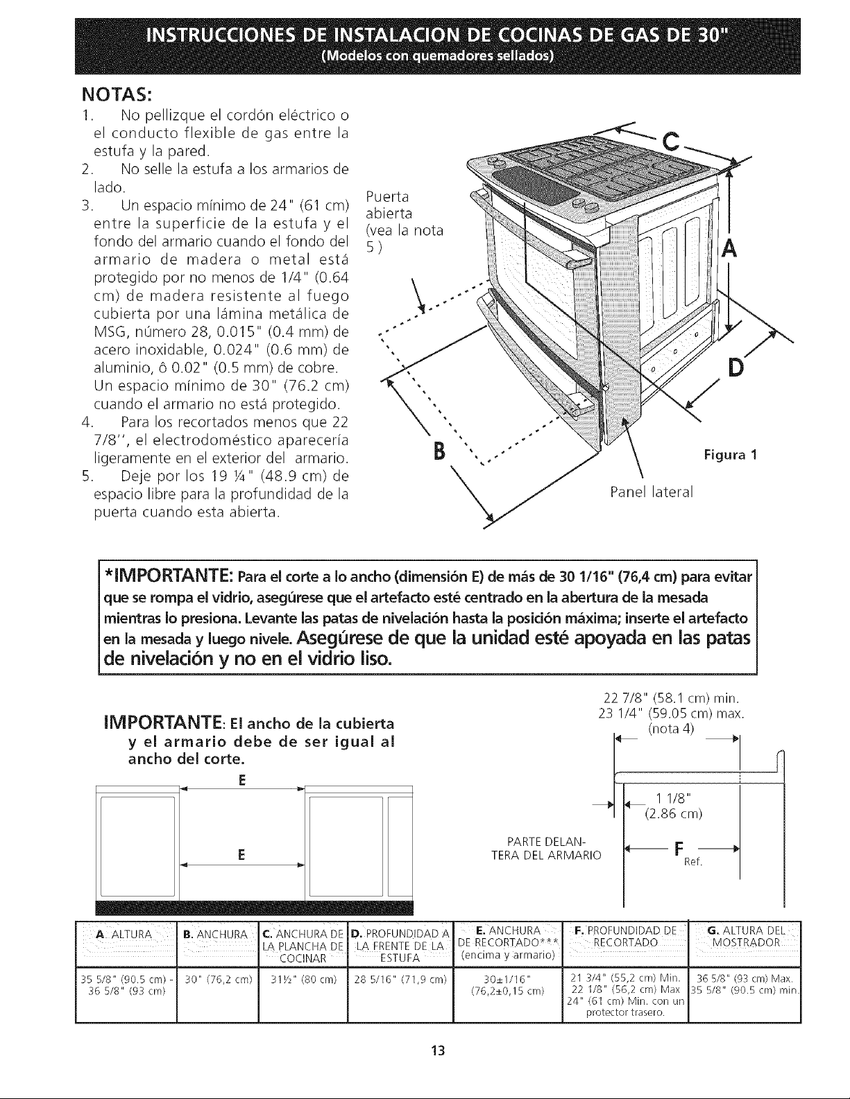
NOTAS:
1. No pellizque el cord6n electrico o
el conducto flexible de gas entre la
estufa y la pared.
2. No selle la estufa a los armarios de
lado.
3. Un espacio minimo de 24" (61 cm)
entre la superficie de la estufa y el
fondo del armario cuando el fondo del
armario de madera o metal est,1
protegido pot no menos de 1/4" (0.64
cm) de madera resistente al fuego
cubierta por una lamina met4lica de
MSG, n0mero 28, 0.015" (0.4 mm) de
acero inoxidable, 0.024" (0.6 mm) de
aluminio, 6 0.02" (0.5 mm) de cobre.
Un espacio minimo de 30" (76.2 cm)
cuando el armario no est,1 protegido.
4. Para los recortados menos que 22
7/8", el electrodomestico apareceria
ligeramente en el exterior del armario.
5. Deje por los 19 Y4" (48.9 cm) de
espacio libre para la profundidad de la
puerta cuando esta abierta.
Puerta
abierta
(vea la nota
5)
÷
÷
A
B Figura 1
Panel lateral
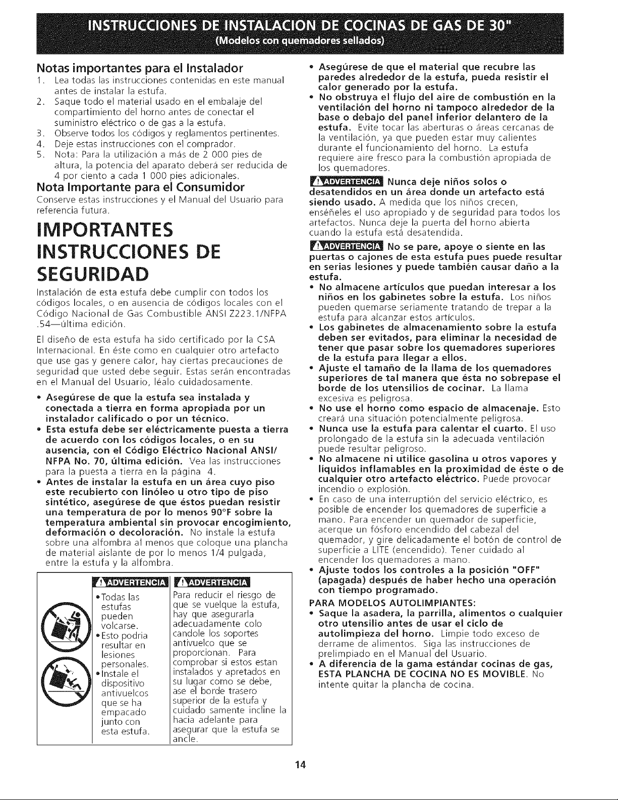
*iMPORTANTE: Para el corte a Io ancho (dimensi6n E) de m&s de 30 1/16" (76,4 cm) para evitar
que se rompa el vidrio, asegurese que el artefacto este centrado en la abertura de la mesada
mientras Io presiona. Levante las patas de nivelaci6n hasta la posici6n maxima; inserte el artefacto
en la mesada y luego nivele. Asegurese de que la unidad est_ apoyada en las patas
de nivelaci6n y no en el vidrio liso.
22 7/8" (58.1 cm) rain.
IMPORTANTE: El ancho de la cubierta 23 I/4" (59.05 crn) max,
(nota 4)
y el armario debe de set igual al
ancho del torte.
E
E
PARTE DELAN-
TERA DEL ARMARIO
r
1 1/8"
_/ (2.86 cm)
--F
Ref.
I m
A ALTURA B. ANCHURA C. ANCHURA DE D. PROFUNDIDAD A E.ANCHURA
I LA PLANCHA DE LA FRENTE DE LA DE RECORTADO*_*
" COCINAR _ ESTUFA (encima y armario)
35 5/8" (90.5cm)- 30" (76,2 cm} 31Y2" (80cm) 28 5/16" (71,9cm) 30+_I/I6"
36 5/8" (93 cm) (76,2_+0,15 cm)
F. PROFUNDIDAD DE G. ALTURA DEL
RECORTADO MOSTRADOR
I
21 3/4" (55,2 cm) Min. 36 5/8" (93 cm) Max.
22 1/8" (56,2 cm) Max 35 5/8" (90.5cm) min.
24" (6I cm) Min. con un
protector trasero.
13
Notas importantes para el Instalador
1. Lea todas las instrucciones contenidas en este manual
antes de instalar la estufa.
2. Saque todo el material usado en el embalaje del
compartimiento del homo antes de conectar el
suministro electrico o de gas a la estufa.
3. Observe todos los cOdigos y reglamentos pertinentes.
4. Deje estas instrucciones con el comprador.
5. Nota: Para la utilizaci6n a m_fs de 2 000 pies de
altura, la potencia del aparato deber_f ser reducida de
4 por ciento a cada 1 000 pies adicionales.
Nota Importante para el Consumidor
Conserve estas instrucciones y el Manual del Usuario para
referencia futura.
IMPORTANTES
INSTRUCCIONES DE
SEGURIDAD
Instalaci6n de esta estufa debe cumplir con todos los
c6digos locales, o en ausencia de c0digos locales con el
C6digo National de Gas Combustible ANSI Z223.1/NFPA
.54--L_ltima edici6n.
El diseflo de esta estufa ha sido certificado por la CSA
International. En este como en cualquier otro artefacto
que use gas y genere calor, hay ciertas precauciones de
seguridad que usted debe seguir. Estas ser_fn encontradas
en el Manual del Usuario, lealo cuidadosamente.
• Asegurese de que la estufa sea instalada y
conectada a tierra en forma apropiada por un
instalador calificado o por un t_cnico.
• Esta estufa debe ser el_ctricamente puesta a tierra
de acuerdo con los codigos locales, o en su
ausenda, con el C6digo El_ctrico National ANSI/
NFPA No. 70, ultima edicion. Vea las instrucciones
para la puesta a tierra en la p_fgina 4.
• Antes de instalar la estufa en un area cuyo piso
este recubierto con lin61eo u otro tipo de piso
sint&tico, asegurese de que &stos puedan resistir
una temperatura de por Io menos 90°F sobre la
temperatura ambiental sin provocar encogimiento,
deformaci6n o decoloraci6n. No instale la estufa
sobre una alfombra al menos que coloque una plancha
de material aislante de por Io menos 1/4 pulgada,
entre la estufa y la alfombra.
oTodas las
estufas
pueden
volcarse.
• Esto podria
resultar en
lesiones
personales.
olnstale el
d ispositivo
antivuelcos
que se ha
empacado
junto con
esta estufa.
Para reducir el riesgo de
que se vuelque la estufa,
hay que asegurarla
adecuadamente colo
candole los soportes
antivuelco que se
proporcionan. Para
comprobar si estos estan
instalados y apretados en
su lugar como se debe,
ase el borde trasero
superior de la estufa y
cuidado samente incline la
hacia adelante para
asegurar que la estufa se
ancle.
• Asegurese de que el material que recubre las
paredes alrededor de la estufa, pueda resistir el
calor generado pot la estufa.
• No obstruya el flujo del aire de combusti6n en la
ventilacion del homo ni tampoco alrededor de la
base o debajo del panel inferior delantero de la
estufa. Evitetocar las aberturaso _ireascercanas de
la ventilaci6n, ya que pueden estar muy calientes
duranteelfuncionamientodel horno. Laestufa
requiere aire fresco para la combusti6n apropiada de
los quemadores.
Nunca deje ni_os solos o
desatendidos en un area donde un artefacto esta
siendo usado. A medida que los nihos crecen,
ense_eles el uso apropiado y de seguridad para todos los
artefactos. Nunca deje la puerta del homo abierta
cuando la estufa est,1 desatendida.
No se pare, apoye o siente en las
puertas o cajones de esta estufa pues puede resultar
en serias lesiones y puede tambien causar da_o a la
estufa.
• No almacene articulos que puedan interesar a los
ni_os en los gabinetes sobre la estufa. Los nihos
pueden quemarse seriamente tratando de trepar a la
estufa para alcanzar estos articulos.
• Los gabinetes de almacenamiento sobre la estufa
deben set evitados, para eliminar la necesidad de
tenet que pasar sobre los quemadores superiores
de la estufa para Ilegar a ellos.
• Ajuste el tama_o de la llama de los quemadores
superiores de tal manera que &sta no sobrepase el
borde de los utensilios decocinar. La llama
excesiva es peligrosa.
• No use el homo como espacio de almacenaje. Esto
crear_i una situaci0n potencialmente peligrosa.
• Nunca use la estufa para calentar el cuarto. El uso
prolongado de la estufa sin la adecuada ventilaciOn
puede resultar peligroso.
• No almacene ni utilice gasolina u otros vapores y
liquidos inflamables en la proximidad de &ste o de
cualquier otro artefacto el&ctrico. Puede provocar
incendio o explosi6n.
• En caso de una interrupti6n del servicio electrico, es
posible de encender los quemadores de superficie a
mano. Para encender un quemador de superficie,
acerque un f0sforo encendido del cabezal del
quemador, y gire delicadamente el bot6n de control de
superficie a LITE (encendido). Tener cuidado al
encender los quemadores a mano.
• Ajuste todos los controles a la position "OFF"
(apagada) despu&s de haber hecho una operaci6n
con tiempo programado.
PARA MODELOS AUTOLIMPIANTES:
• Saque la asadera, la parrilla, alimentos o cualquier
otro utensilio antes de usar el cido de
autolimpiezadel homo. Limpietodoexceso de
derrame dealimentos. Siga las instruccionesde
prelimpiado en el Manual del Usuario.
• A diferencia de la gama estandar cocinas de gas,
ESTA PLANCHA DE COCINA NO ES MOVlBLE. No
intente quitar la plancha de cocina.
14
ConstrucciOn del armario
F._I__ Para eliminar el riesgo de quemaduras o
de fuego tratando de alcanzar algo por encima de las
zonas calientes, evite de colocar articulos sobre la cocina.
Si cree necesitar este espacio, el riesgo puede disminuir si
instala un sombrerete que proteja horizontalmente un
minimo de 5" (12.7cm) sobre la base del armario.
PreparatiOn del mostrador
• Las extremidades de la cocina sobrepasan el horde de
su mostrador.
• Si tiene un mostrador con las extremidades
cuadradas (planas), no se necesita ninguna
preparaciOn del mostrador.
• El reborde de frente de mostradores moldeados
deben tenet hordes moldeados a 3/4" (1.9cm) a partir
de cada extremidad de la apertura (Figura 2).
• Los mostradores enazulejos deberan necesitar un
recorte de 3/4" (1.9 cm) a partit de cada extremidad
y/o un horde redondeado aplanado (Figura 2).
%-
(1.9 cm)
Anchura
de hueco
rain,
J
(81cm)
Mostrador moldeado o
enazulejo recortado 3/4" (1.9 cm)
hacia atr_s en las esquinas de
(1,9 cm) frente de la abertura del
I Figura 2
mostrador.
• Si el ancho de la abertura del mostrador es m_s
grande que 30 1/16" (76,4 cm), ajuste alas
dimensiones corno para el 3/4" (1.9).
• Para
29"(73.7 cm) (Figura 3):23/16"
2 3/15" cm)
(5.56 cm)
la Anchura existente del Recorte de el
Figura 3
Quite el 2 3/16" de
material de frente a la
parte posteriora.
11/4"
(3.2 cm)
3o,,j
_" 311/2
(80 cm)
1vz' _ Mostrador moldeado o enazulejo
(3.2cm) recortado 3/4" (1.9 cm) hacia atras en las
I esquinas de frente de la abertura del
mostrador.
• El mostrador deber ser nivelado. Coloque un
nivelador sobre el mostrador, primero de lado a lado y
luego del frente hacia atras. Si el mostrador no esta
nivelado, la cocina no estara nivelada. El homo debe
set nivelado para tenet resultados satisfactorios al
hornear. Las extremidades de la plancha de la cocinar
sobrepasan los hordes de la abertura del mostrador.
15
FJl Proporcione un suministro de gas
adecuado
Cuando se envia de la fabrica, Esta unidad ha sido
ajustada para operar con un mOItiple de admisiOn para
gas natural de 4" (10.16 cm)(1.0 kPa). Un regulador de
presiOn convertible esta conectado a la valvula
distribuidora y DEBE set conectado con la tuberia del
suministro de gas. Si eljuego de conversion del propano
LP/Propano se ha utilizado, sigue las instrucciones
proporcionadas el juego para convertir el regulador de
presiOn al uso de LP/Propano.
se debe de tenet cuidado durante la instalaciOn de la
estufa para no obstruir el flujo de aire de combustion y
ventilation
Para la operation apropriada, la maxima presiOn de
entrada al regulador no debe execeder la presiOn de una
columna de agua de 14"(35,56 cm) (3.5 kPa). La presiOn
de entrada al regulador debe set pot Io menos I " (.25
kPa) mas grande que la valvula distribuidora.Ejemplos: Si
regulador se pone para el gas natural con una presiOn de
4"(10,16 cm), la presiOn de entrada al regulador debe
set pot Io menos 5"(12.60 cm); si el regulador se ha
convertido para gas LP/Propane 10"(25,4 cm)la presiOn
de entrada al regulador debe set pot Io menos 11 "(27,9
cm).
Un examen de detection de fugas del aparato debe ser
realizado segOn las instrucciones en el paso 4.
La linea de fuente de gas debe set de Y2" 0 de 3A".
Selle las aperturas
sella todas las aperturas en la pared detras de la estufa y
en el suelo debajo de la estufa despu_s que la linea del
suministro de gas sea instalada.
Conecte la estufa al suministro de gas
Importante: Quite todo el material de embalaje y
literatura de la estufa antes de conectar el gas y la
fuente el_ctrica.
Para evitar fugas, aplique sellador de tuberias en todas
las partes roscadas
machos (exterior) de la
tuberia. El regulador se
encuentra en el lugar que
se muestra en la
illustration. (Figura 4)
No
permita que el
regulador gire sobre la
tuberi,i al apretar las
uniones.
Figura 4
Ubicacion del regulador
de presiOn
Conecte el ReguJador de Presi6n
El regulador de presiOn esta ya instalada para la estufa.
V.__ No haga la conexiOn demasiado
apretada. El regulador es de die cast. El apretar
demasiado puede agrietar el regulador dando por
resultado una fuga de gas y un fuego o una explosion.
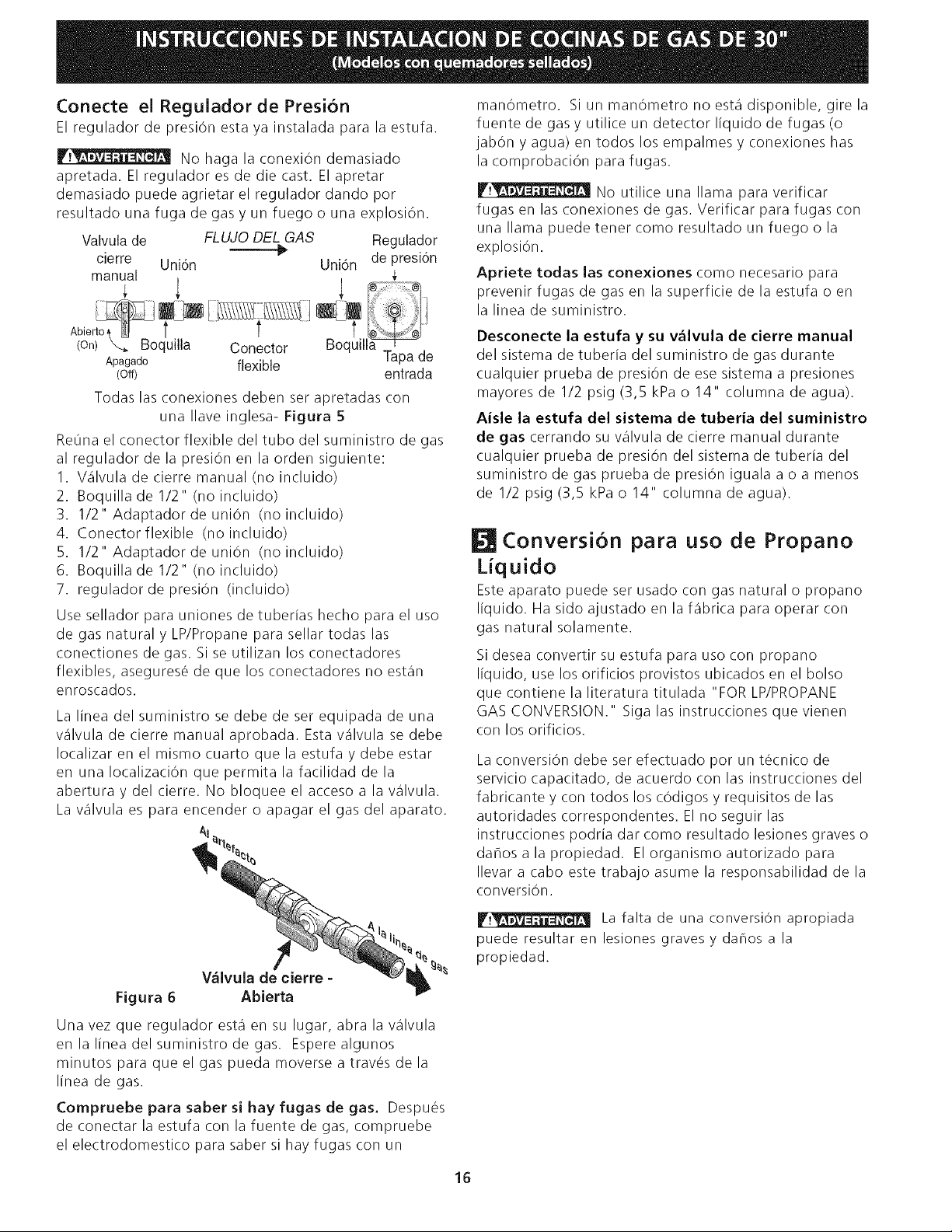
Valvula de FLUJO DEL GAS Regulador
_" de presi6n
cierre Uni6n Uni6n
manual
(on) _._ Boquilla Conector Boquill_
Apagado flexible Tapa de
(Off) entrada
Todas las conexiones deben ser apretadas con
una Ilave inglesa- Figura 5
ReOna el conector flexible del tubo del suministro de gas
al regulador de la presiOn en la orden siguiente:
I. Valvula de cierre manual (no incluido)
2. Boquilla de 1/2" (no incluido)
3. 1/2" Adaptador de union (no incluido)
4. Conectorflexible (no incluido)
5. 1/2" Adaptador de union (no incluido)
6. Boquilla de 1/2" (no incluido)
7. regulador de presiOn (incluido)
Use sellador para uniones de tuberias hecho para el uso
de gas natural y LP/Propane para sellar todas las
conectiones de gas. Si se utilizan los conectadores
flexibles, asegurese de que los conectadores no estan
enroscados.
La linea del suministro se debe de ser equipada de una
valvula de cierre manual aprobada. Esta valvula se debe
Iocalizar en el mismo cuarto que la estufa y debe estar
en una IocalizaciOn que permita la facilidad de la
abertura y del cierre. No bloquee el acceso a la valvula.
La valvula es para encender o apagar el gas del aparato.
Am
manOmetro. SiunmanOmetronoestadisponible, girela
fuente de gas y utilice un detector liquido de fugas (o
jabOn y agua) en todos los empalmes y conexiones has
la comprobaciOn para fugas.
IF.__ No utilice una llama para verificar
fugas en las conexiones de gas. Verificar para fugas con
una llama puede tener como resultado un fuego o la
explosion.
Apriete todas las conexiones como necesario para
prevenir fugas de gas en la superficie de la estufa o en
la linea de suministro.
Desconecte la estufa y su v_lvula de cierre manual
del sisterna de tuberia del suministro de gas durante
cualquier prueba de presiOn de ese sistema a presiones
mayores de 1/2 psig (3,5 kPa o 14" columna de agua).
Aisle la estufa del sistema de tuberia del suministro
de gas cerrando su valvula de cierre manual durante
cualquier prueba de presiOn del sistema de tuberia del
suministro de gas prueba de presion iguala a o a menos
de 1/2 psig (3,5 kPa o 14" columna de agua).
Conversi6n para uso de Propano
Liquido
Este aparato puede ser usado con gas natural o propano
liquido. Ha sido ajustado en la %brica para operar con
gas natural solamente.
Si desea convertir su estufa para uso con propano
liquido, use los orificios provistos ubicados en el bolso
que contiene la literatura titulada "FOR LP/PROPANE
GAS CONVERSION." Siga las instrucciones que vienen
con los orificios.
La conversion debe ser efectuado por un tOcnico de
servicio capacitado, de acuerdo con las instrucciones del
fabricante y con todos los cOdigos y requisitos de las
autoridades correspondentes. El no seguir las
instrucciones podria dar como resultado lesiones graves o
dahosalapropiedad. EIorganismoautorizadopara
Ilevar a cabo este trabajo asume la responsabilidad de la
conversion.
V_lvula de cierre -
Figura 6 Abierta
Una vez que regulador esta en su lugar, abra la valvula
enlalineadelsuministrodegas. Esperealgunos
minutos para que el gas pueda moverse a travOs de la
linea de gas.
Compruebe para saber si hay fugas de gas. Despues
de conectar la estufa con la fuente de gas, compruebe
el electrodomestico para saber si hay fugas con un
La falta de una conversion apropiada
puede resultar en lesiones graves y da_os a la
propiedad.
16
Requisitos el ctricos
120 voltio, 60 Hertzio, circuito dedicado
apropiadamente puestos a tierra protegido por un
circuito de amperio o fusible de demora de tiempo de
15 amp. Nota: no es recomendado instalarlo con un
Interruptor (GFI) de puesta a tierra.
No utiiice una extensi6n con esta estufa.
Instrucdones de puesta a tierra
IMPORTANTE Por favor lea con cuidado.
Para la seguridad personal, este aparato debe set
puesto a tierra apropiadamente.
El cable del suministro electrico de esta estufa esta
equipado con un enchufe de tres patillas (para puesta a
tierra) que coincida con un enchufe de pared estandar
con puesta a tierra de tres patillas para minimizar la
posibilidad que se produzcan descargas electricas.
El cliente debera encargar a un t_cnico para asegurarse
de que el enchufe se encuentra debidemente conectado
a tierra y polarizado.
En lugares en los que aya un enchufe de pared estandar
de dos patillas, el cliente tendra resposabilidad directa y
la obligacion de reemplazarlo por un enchufe de pared
de tres patillas debidemente cableado a tierra.
La mudanza del aparato para
reparaciones o limpieza
Apague la corriente electrica a la estufa a la fuente de
poder principal, y apague la wilvula de cierre manual de
gas. Asegt_resede que la estufa este fresca. Quite el caj6n
de servicio (el caj6n calentador en algunos modelos) y abre
la puerta del horno. Levante la frente de la estufa y
deslicela fuera de la abertura sin crear tensi6n desmedida
sobre el conducto flexible de gas. Asegurese de no
pellizque el conducto flexible de gas detr_is de la estufa al
reemplazar la unidad en la abertura. Reemplace el caj6n,
cierre la puerta y enciende el gas y la corriente electrica a
la estufa.
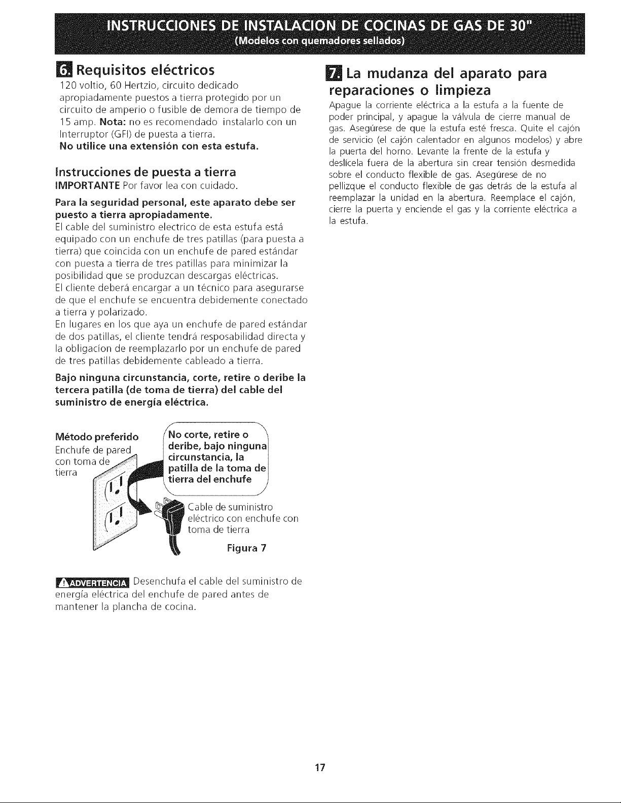
Bajo ninguna circunstancia, corte, retire o deribe la
tercera patilla (de toma de tierra) del cable del
suministro de energia el_ctrica.
M_todo preferido
Enchufe de pared
con toma de
tierra
retire o
Cable de suministro
el_ctrico con enchufe con
toma de tierra
Figura 7
Desenchufa el cable del suministro de
energia el6ctrica del enchufe de pared antes de
mantener la plancha de cocina.
17
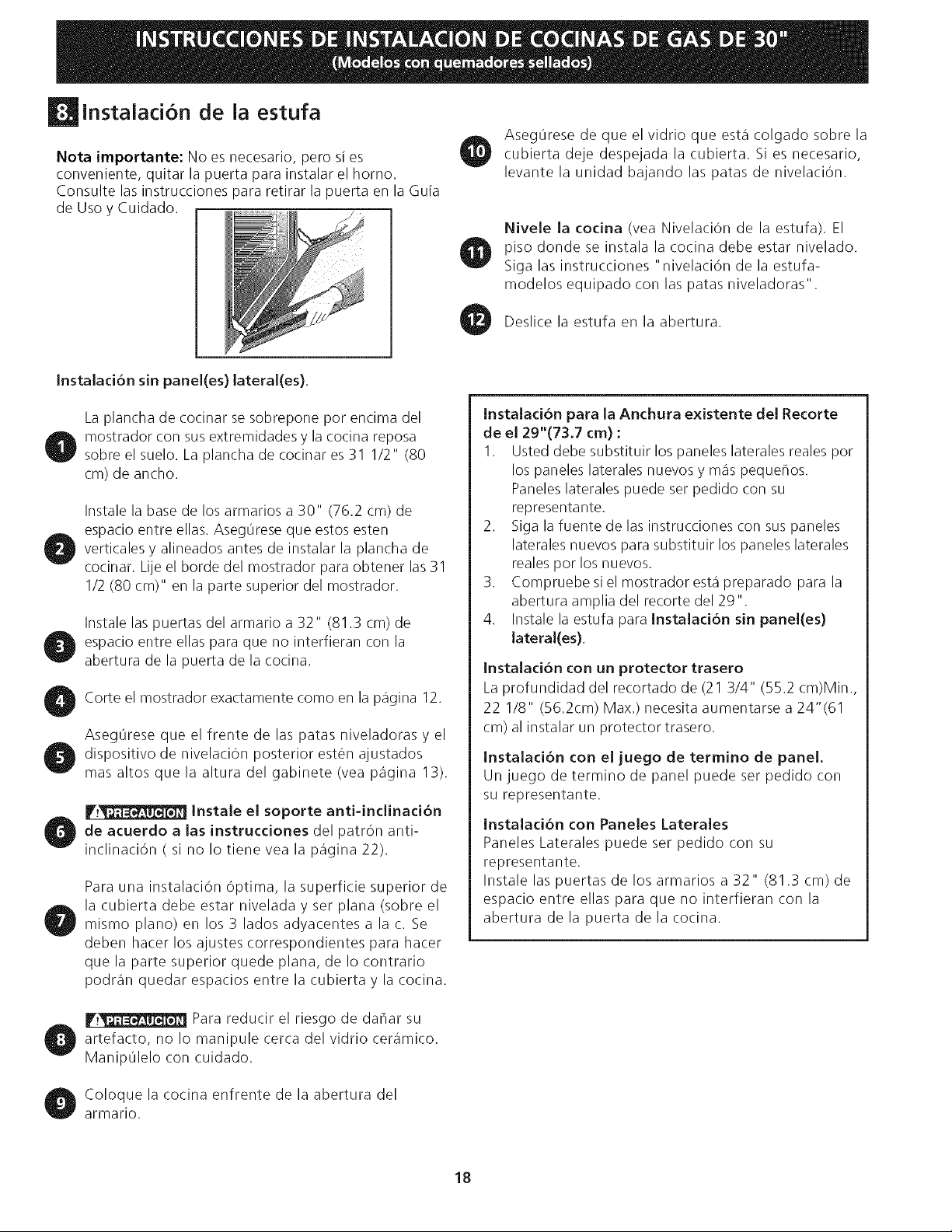
instalaci6n de la estufa
Nota importante: No es necesario, pero si es
conveniente, quitar la puerta para instalar el horno.
Consulte las instrucciones para retirar la puerta en la Guia
de Uso y Cuidado.
Aseg0rese de que el vidrio que esta colgado sobre la
cubierta deje despejada la cubierta. Si es necesario,
levante la unidad bajando las patas de nivelaci6n.
Nivele la codna (vea NivelaciOn de la estufa). El
piso donde se instala la cocina debe estar nivelado.
Siga las instrucciones "nivelaci6n de la estufa-
modelos equipado con las patas niveladoras".
Deslice la estufa en la abertura.
JnstaJaci6n sin paneJ(es) Jateral(es).
La plancha de cocinar se sobrepone pot encima del
mostrador con sus extremidades y la cocina reposa
sobre el suelo. La plancha de cocinar es 31 I/2" (80
cm) de ancho.
Instale la base de los armarios a 30" (76.2 cm) de
espacio entre elias. Aseg0rese que estos esten
verticales y alineados antes de instalar la plancha de
cocinar. Lije el horde del mostrador para obtener las 31
I/2 (80 cm)" en la parte superior del mostrador.
Instale las puertas del armario a 32" (81.3 cm) de
espacio entre elias para que no interfieran con la
abertura de la puerta de la cocina.
Corte el mostrador exactamente como en la pagina 12.
Aseg0rese que el frente de las patas niveladoras y el
dispositivo de nivelaci6n posterior est@ ajustados
mas altos que la altura del gabinete (vea pagina 13).
r.__ Instale el soporte anti-inclinad6n
de acuerdo alas instrucdones del patr6n anti-
inclinaci6n ( si no Io tiene vea la pagina 22).
Para una instalaci6n 6ptima, la superficie superior de
la cubierta debe estar nivelada y set plana (sobre el
mismo piano) en los 3 lados adyacentes a la c. Se
deben hacer los ajustes correspondientes para hacer
que la parte superior quede plana, de Io contrario
podran quedar espacios entre la cubierta y la cocina.
Ir.__ Para reducir el riesgo de dahar su
artefacto, no Io manipule cerca del vidrio ceramico.
Manip01elo con cuidado.
Coloque la cocina enfrente de la abertura del
armario.
InstaJad6n para la Anchura existente deJ Recorte
de el 29"(73.7 cm) :
I. Usted debe substituir los paneles laterales reales pot
los paneles laterales nuevos y mas pequehos.
Paneles laterales puede set pedido con su
representante.
2. Siga la fuente de las instrucciones con sus paneles
laterales nuevos para substituir los paneles laterales
reales pot los nuevos.
3. Compruebe si el mostrador esta preparado para la
abertura amplia del recorte de129 ".
4. Instale la estufa para Instalad6n sin panei(es)
lateral(es).
Instalaci6n con un protector trasero
La profundidad del recortado de (21 3/4" (55.2 cm)Min.,
22 I/8" (56.2cm) Max.) necesita aumentarse a 24"(61
cm) al instalar un protector trasero.
Instalad6n con el juego de termino de panel.
Un juego de termino de panel puede set pedido con
su representante.
Instalad6n con Paneles Laterales
Paneles Laterales puede set pedido con su
representante.
Instale las puertas de los armarios a 32" (81.3 cm) de
espacio entre elias para que no interfieran con la
abertura de la puerta de la cocina.
18
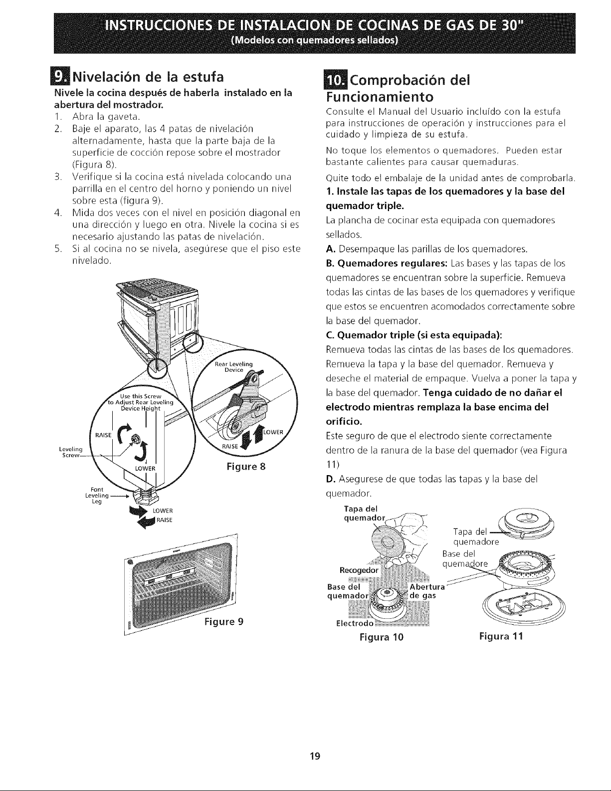
NiveJaci6n de la estufa
Nivele la codna despu_s de haberla instalado en la
abertura deJ mostrador.
I. Abra la gaveta.
2. Baje el aparato, las 4 patas de nivelaciOn
alternadamente, hasta que la parte baja de la
superficie de cocciOn repose sobre el mostrador
(Figura 8).
3. Verifique si la cocina esta nivelada colocando una
parrilla en el centro del homo y poniendo un nivel
sobre esta (figura 9).
4. Mida dos veces con el nivel en posici6n diagonal en
una direcciOn y luego en otra. Nivele la cocina si es
necesario ajustando las patas de nivelaciOn.
5. Sial cocina no se nivela, asegOrese que el piso este
nivelado.
Leveling
Font
Leveling
Leg
LOWER
RAISE
Figure 8
Comprobacion del
Funcionamiento
Consulte el Manual del Usuario incluido con la estufa
para instrucciones de operaciOn y instrucciones para el
cuidado y limpieza de su estufa.
No toque los elementoso quemadores. Pueden estar
bastante calientes para causar quemaduras.
Quite todo el embalaje de la unidad antes de comprobarla.
1. Instale las tapas de los quemadores y la base del
quemador triple.
La plancha de cocinar esta equipada con quemadores
sellados.
A. Desempaque las parillas de los quemadores.
B. Quemadores regulares: Las bases y las tapas de los
quemadores se encuentran sobre la superficie. Remueva
todas las cintas de las bases de los quemadores y verifique
que estos se encuentren acomodados correctamente sobre
la base del quemador.
C. Quemador triple (si esta equipada):
Rernueva todas las cintas de las bases de los quemadores.
Remueva la tapa y la base del quemador. Remueva y
deseche el material de empaque. Vuelva a poner la tapa y
la base del quemador. Tenga cuidado de no daEar el
electrodo rnientras rernplaza la base encirna del
orificio.
Esteseguro de que el electrodo siente correctamente
dentro de la ranura de la base del quemador (vea Figura
11)
D. Asegurese de que todas las tapas y la base del
quemador.
Tapa del
quemado_
Recogedor
Base del
Tapa
quemadore
Base del
Abertura
de gas
Figure 9 EJectrodo
Figura 10
Figura 11
19
2. Enciende la corriente el_ctrica y abre la v61vula
principal de cierre.
3. Comprobaci6n de los Encendedores
Elfuncionamiento de los encendedores el6ctricos
debe ser comprobado despues de que la estufa y los
conectores a la tuberia de suministro de gas hayan
sido comprobados por escapes y la estufa haya sido
conectadael6ctricamente. Paracomprobarqueel
encendido sea correcto:
I. Empuje y gire una perilla del quemador superior
hastala posiciOn LITE(encender). Sepodriaoirel
encendedor haciendo chispas.
2. El quemador se debera encender en cuatro (4)
segundos para un funcionamiento normal, luego de
que el aire haya sido purgado de la tuberia de
suministro de gas. Controlevisualmentequeel
quemador se hay encendido.
3. Luego que el quemador se haya encendido, la perilla
debe ser girada fuera de la posiciOn LITE.
Cada quemador tiene su encendedor individual.
Controle las perillas separadamente hasta que todas
las valvulas hayan sido controladas.
4. Ajuste bajo ("LO") ara la v_lvula de los quernadores
de superficie (Figura 12)
a. Presione y gire el control hasta la posiciOn LITEpara
prender los quemadores.
b. Gire r_pidamente gire la perilla a la POSICIONMAS
BAJA.
c. Sielquemadorseapaga, reajuste el control a OFF.
d. Retire la perilla del quemador de superficie.
e. Inserte un destornillador fino-aplanado en el orifico del
vastago de la valvula e inserte en el tornillo ranurado.
El tamaflo de la llama puede aumentarse o
disminuirse dandole vuelta al tornillo. D6 vuelta en
sentido opuesto alas manecillas del reloj para
aumentarel tamaflodelallama. D6vueltaen
sentido alas manecillas del reloj para disminuir la
llama. Ajuste la llama hasta que usted puede dar
vuelta rapidamente a la perilla de la posiciOn LITEa la
POSICION MAS BAJA sin extinguir la llama. La llama
debe ser tan pequefla como sea posible sin apagarse.
Nota: El ajuste de la mezcla del aire no se requiere
en los quemadores de superficie
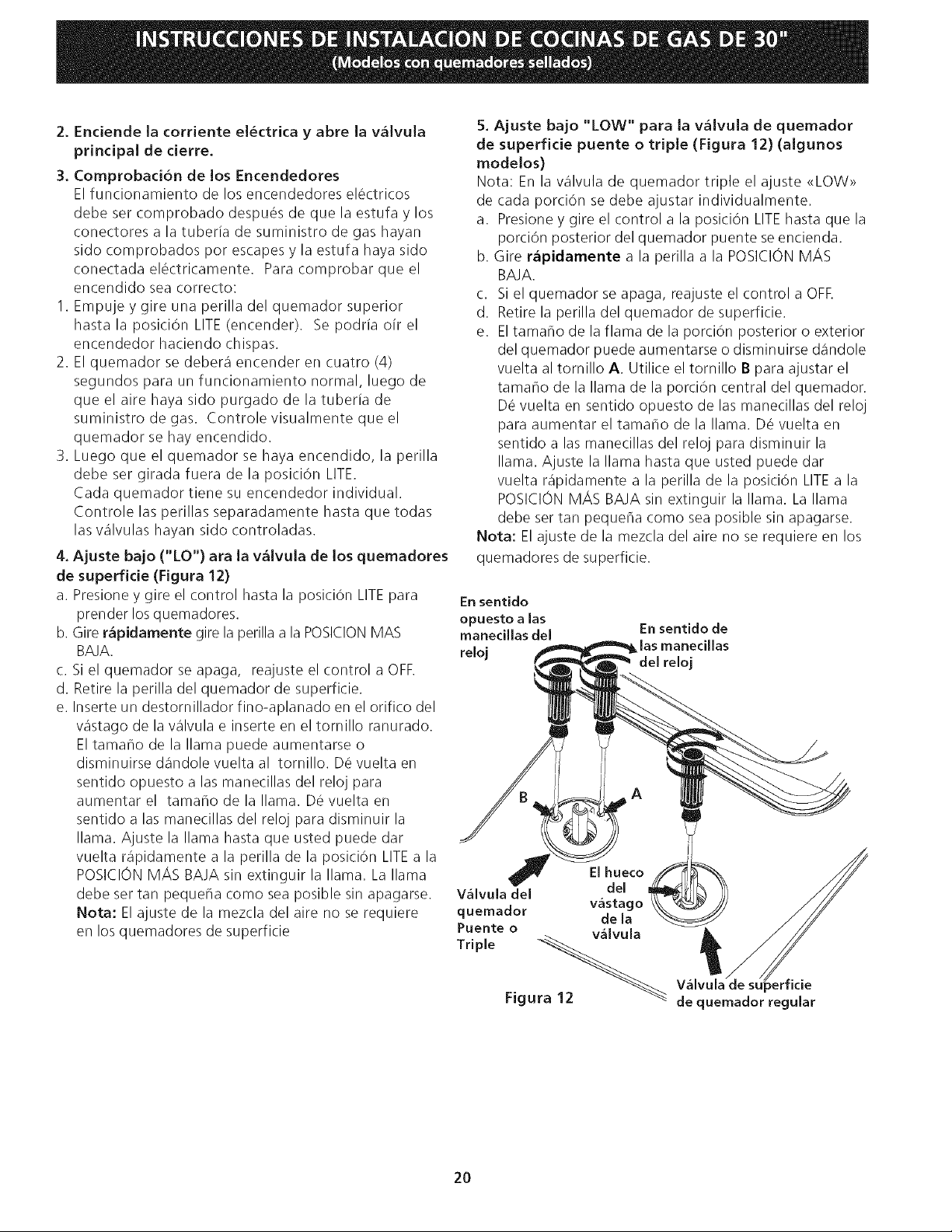
5. Ajuste bajo "LOW" para la v_Ivula de quemador
de superficie puente o triple (Figura 12) (algunos
modelos)
Nota: En la valvula de quemador triple el ajuste <<LOW>>
de cada porci6n se debe ajustar individualmente.
a. Presione y gire el control a la position LITEhasta que la
porci6n posterior del quemador puente se encienda.
b. Gire r_pidamente a la perilla a la POSICION MAS
BAJA.
c. Si el quemador se apaga, reajuste el control a OFR
d. Retire la perilla del quemador de superficie.
e. El tamaho de la flama de la porci6n posterior o exterior
del quemador puede aumentarse o disminuirse dandole
vuelta al tornillo A. Utilice el tornillo B para ajustar el
tamaho de la llama de la porci6n central del quemador.
D_ vuelta en sentido opuesto de las manecillas del reloj
para aumentar el tamaho de la llama. D6 vuelta en
sentido alas manecillas del reloj para disminuir la
llama. Ajuste la llama hasta que usted puede dar
vuelta r@idamente a la perilla de la posiciOn LITEa la
POSICION MAS BAJA sin extinguir la llama. La llama
debe ser tan pequeha como sea posible sin apagarse.
Nora: El ajuste de la mezcla del aire no se requiere en los
quemadores de superficie.
En sentido
opuesto a las
manecillas del En sentido de
reloj las manecillas
del reloj
J El hueco
V_Ivula del del
quernador v_stac
de la
Puente o v_Ivula
Triple -_
Figura 12
._rficie
de quemador regular
2O
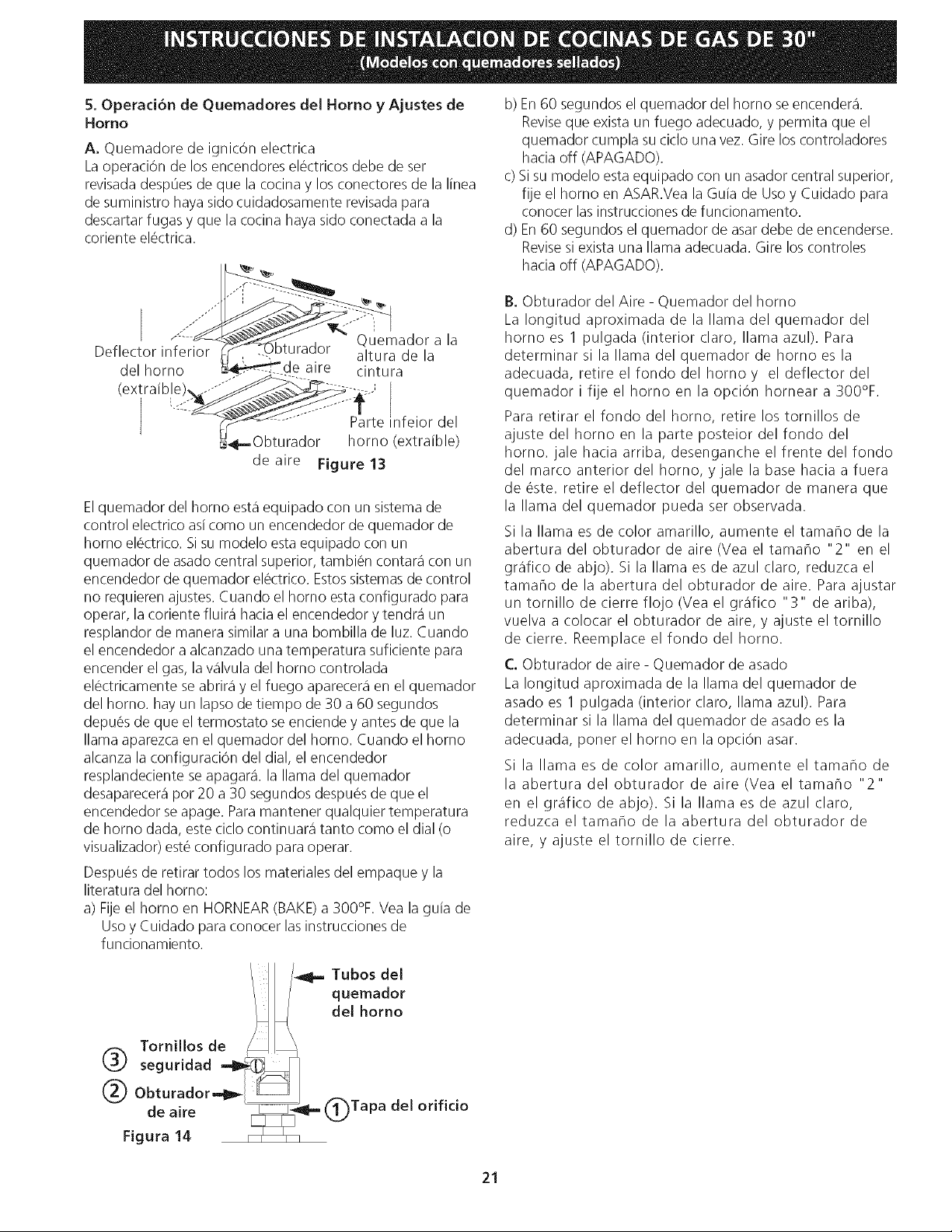
5.OperacJ6ndeQuemadoresdeJHornoy Ajustesde
Homo
A. Quemadoredeignic6nelectrica
LaoperaciOndelosencendoreselectricosdebedeser
revisadadespOesdequelacocinaylosconectoresdelalinea
desuministrohayasidocuidadosamenterevisadapara
descartarfugasy quelacocinahayasidoconectadaala
corienteel_ctrica.
b)En60segundoselquemadordelhomoseencendera.
Revisequeexistaunfuegoadecuado,ypermitaqueel
quemadorcumplasuciclounavez.Gireloscontroladores
haciaoff(APAGADO).
c)Sisumodeloestaequipadoconunasadorcentralsuperior,
fijeelhomoenASAR.VealaGuiadeUsoy Cuidado para
conocer las instrucciones de funcionamento.
d) En 60 segundos el quemador de asar debe de encenderse.
Revisesi exista una llama adecuada. Gire los controles
hacia off (APAGADO).
Quemador a la
Deflector inferior oturador altura de la
del homo aire cintura
(extraible nfeior
Parte del
homo (extraible)
deaire Figure 13
Elquemador del homo esta equipado con un sistema de
control electrico asi como un encendedor de quemador de
homo el@ctrico.Si su modelo esta equipado con un
quemador de asado central superior, tambi@ncontara con un
encendedor de quemador el@ctrico.Estossistemasde control
no requieren ajustes. Cuando el homo esta configurado para
operar, la coriente fluir_ hacia el encendedor y tendra un
resplandor de manera similar a una bombilla de luz. Cuando
el encendedor a alcanzado una temperatura suficiente para
encender el gas, la valvula del homo controlada
el@ctricamentese abrira y el fuego aparecera en el quemador
del homo. hay un lapso de tiempo de 30 a 60 segundos
depu@sde que el termostato se enciende y antes de que la
llama aparezca en el quemador del homo. Cuando el homo
alcanza la configuraci6n del dial, el encendedor
resplandeciente se apagar& la llama del quemador
desaparecera por 20 a 30 segundos despu_s de que el
encendedor se apage. Para mantener qualquier temperatura
de homo dada, este ciclo continuara tanto como el dial (o
visualizador) este configurado para operar.
Despu@sde retirar todos los materiales del empaque y la
literatura del homo:
a) Fije el homo en HORNEAR(BAKE)a 300°F. Vea la guia de
Uso y Cuidado para conocer las instrucciones de
funcionamiento.
B. Obturador del Aire - Quemador del homo
La Iongitud aproximada de la llama del quemador del
homo es 1 pulgada (interior claro, llama azul). Para
determinar si la llama del quemador de homo es la
adecuada, retireelfondodelhomoy el deflectordel
quemador i fije el homo en la opci6n homear a 300%.
Para retirar el fondo del homo, retire los tomillos de
ajuste del homo en la parte posteior del fondo del
homo. jale hacia arriba, desenganche el frente del fondo
del marco anterior del homo, y jale la base hacia a fuera
de @ste.retire el deflector del quemador de manera que
la llama del quemador pueda ser observada.
Si la llama es de color amarillo, aumente el tamar/o de la
abertura del obturador de aire (Vea el tamaflo "2" en el
grafico de abjo). Si la llama es de azul claro, reduzca el
tamaflo de la abertura del obturador de aire. Para ajustar
un tomillo de cierre flojo (Vea el grafico "3" de ariba),
vuelva a colocar el obturador de aire, y ajuste el tomillo
de cierre. Reemplace el fondo del homo.
C. Obturador de aire - Quemador de asado
La Iongitud aproximada de la llama del quemador de
asado es 1 pulgada (interior claro, llama azul). Para
determinar si la llama del quemador de asado es la
adecuada, poner el homo en la opci6n asar.
Si la llama es de color amarillo, aumente el tamaho de
la abertura del obturador de aire (Vea el tamaho "2"
en el grafico de abjo). Si la llama es de azul claro,
reduzca el tamaF/o de la abertura del obturador de
aire, y ajuste el tomillo de cierre.
II /_ Tubos del
/ quemador
del homo
Tornillos de _11_
seguridad __]
_ i:!!:ar:!° r _Jm_-_J_'_ @ Tapa del OrificiO
21
Despues de TermMar la Instalad6n
Asegurese de que todos los controles esten en la
posici6n OFF (apagada).
Aseg0rese de que el fluir del aire de combusti6n y de
ventilaci6n a la estufa no este obstruido.
Ubicad6n del Nemero de Modelo y de
Serie
La plata con el numero de serie est,1 ubicada en el
marco delantero del homo detr_is de la puerta del
homo (algunos modelos) o detr_is del cajOn (algunos
modelos).
Cuando haga pedidos de repuestos o solicite
informaciOn con respecto a su estufa, este siempre
seguro de incluir el n0mero de modelo y de serie y el
n0mero o letra del Iote de la plata de serie de su
estufa.
La plata con el n0mero de serie tambien le da la
potencia nominal de los quemadores, el tipo de
combustible y la presiOn a la cual fue ajustada la estufa
en la f_ibrica,
Antes de Llamar al Servido
Lea la secciOn Evite Llamadas de Servicio en su Manual
del Usuario. Esto le podr_i ahorrar tiempo y gastos.
Esta lista incluye ocurrencias comunes que no son el
resultado de defectos de materiales o fabricaciOn de
este artefacto.
Lea la garantia y la informaciOn sobre el servtcio en
su Manual del Usuario para obtener el n0mero de
telefono gratuitoyla direcci6n delservicio. Porfavor
Ilame o escriba si tiene preguntas acerca de su estufa
o necesita repuestos.
22
instrucciones de instaiaci6n de la
fijaci6n anti-inclinaci6n
F.__ Para reducir el riesgo de inclinaciOn de la
cocina, _sta debe ser asegurada hacia el piso con las
fijaciones de anti-inclinaciOn y los tornillos que vienen con
la cocina. Estos componentes se encuentran en el homo.
Si no instala las fijaciones, corre el riesgo que su cocina
pueda inclinarse si pone demasiado peso en ella o si un
niho sube sobre 6sta. Esto podria ocasionar graves heridas
causadas por liquidos calientes o por la propia cocina.
Siga estas instrucciones para instalar las fijaciones de anti-
inclinaciOn.
Si la cocina es trasladada a otro lugar, las fijaciones de anti-
inclinaciOn deben tambi_n ser trasladados con la cocina.
Herramientas necesarias:
Llave de tuerca ajustable
Trinquete
Taladro el_ctrico con barrena de 1/8"(0,32 cm)
Aprietatuercas de 5/I 6"(0,8 cm)
Nivel
Abrazadera sujetada al suelo en la parte trasera de la
cocina para tener asida la parte posterior de la cocina. AI
fijarla al suelo, verificar que los tornillos no atraviesen la
instalaciOn el6ctrica o de fontaneria. Lostornillos provistos
sirven para madera o concreto.
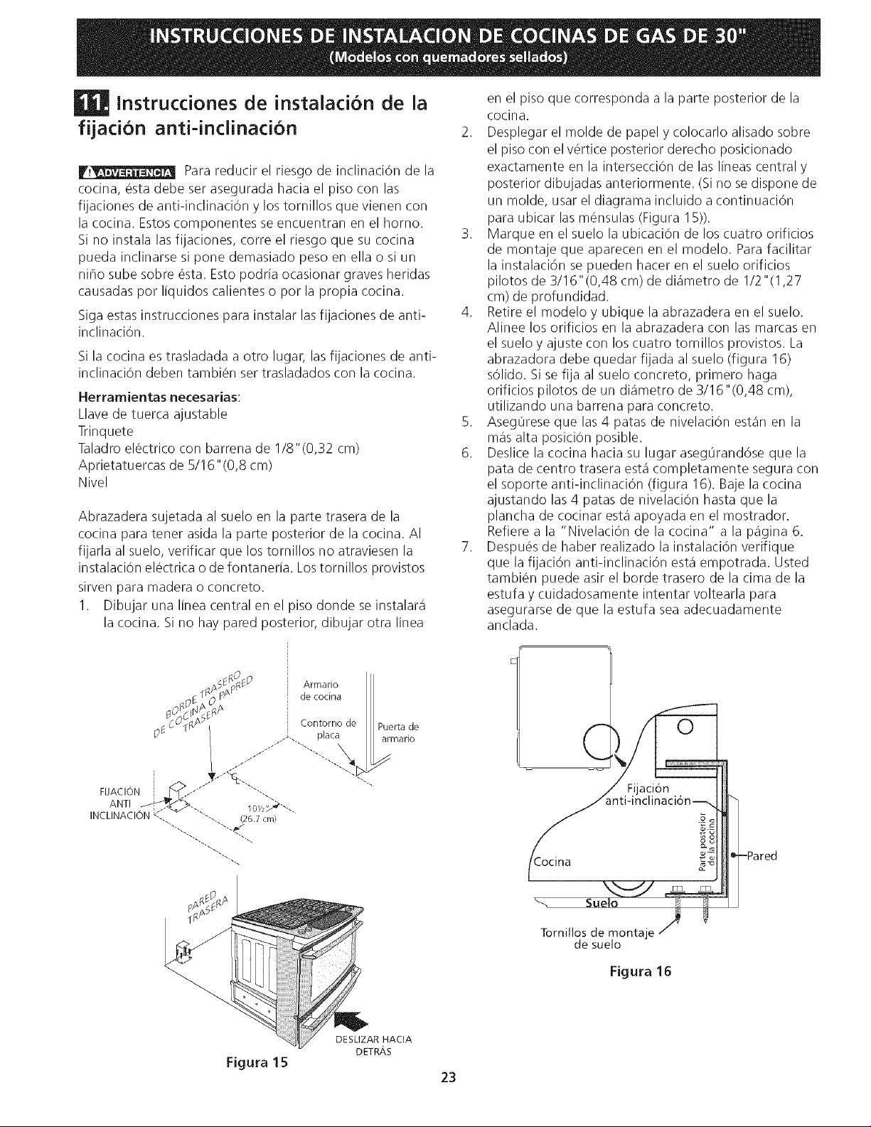
1. Dibujar una linea central en el piso donde se instalara
la cocina. Si no hay pared posterior, dibujar otra linea
en el piso que corresponda a la parte posterior de la
cocina.
2. Desplegar el molde de papel y colocarlo alisado sobre
el piso con el v_rtice posterior derecho posicionado
exactamente en la intersecciOn de las lineas central y
posterior dibujadas anteriormente. (Sino se dispone de
un molde, usar el diagrama incluido a continuaci6n
para ubicar las m6nsulas (Figura 15)).
3. Marque en el suelo la ubicaciOn de los cuatro orificios
de montaje que aparecen en el modelo. Para facilitar
la instalaci6n se pueden hacer en el suelo orificios
pilotos de 3/16"(0,48 cm) de diametro de 1/2"(1,27
cm) de profundidad.
4. Retire el modelo y ubique la abrazadera en el suelo.
Alinee los orificios en la abrazadera con las marcas en
el suelo y ajuste con los cuatro tornillos provistos. La
abrazadora debe quedar fijada al suelo (figura 16)
sOlido. Si se fija al suelo concreto, primero haga
orificios pilotos de un diametro de 3/16"(0,48 cm),
utilizando una barrena para concreto.
5. Aseg0rese que las 4 patas de nivelaciOn estan en la
mas alta posiciOn posible.
6. Deslice la cocina hacia su lugar aseg0rand6se que la
pata de centro trasera esta completamente segura con
el soporte anti-inclinaci6n (figura 16). Baje la cocina
ajustando las 4 patas de nivelaciOn hasta que la
plancha de cocinar esta apoyada en el mostrador.
Refiere a la "NivelaciOn de la cocina" a la pagina 6.
7. Despu_s de haber realizado la instalaci6n verifique
que la fijaciOn anti-inclinaciOn esta empotrada. Usted
tambi6n puede asir el horde trasero de la cima de la
estufa y cuidadosamente intentar voltearla para
asegurarse de que la estufa sea adecuadamente
anclada.
(
O
aclon
Tornillos de montaje
de suelo
Figura 16
DESLIZAR HACIA
DETR,_S
Figura 15
23
UNINSTALLATEURQUALIFIEDOITEFFECTUERL'INSTALLATION ET LE SERVICE
iMPORTANT: CONSERVEZ CESiNSTRUCTiONS POUR LES INSPECTEURSLOCAUX.
USEZ CESiNSTRUCTiONS ETCONSERVEZ-LESPOUR REFERENCESULTERIEURES.
_I_P__ Si les instructions de ce manuel ne sont pas suivies a la lettre,
il pourrait en r_sulter un incendie ou une explosion susceptible de causer des
dommages materiels, des blessures ou re@me la mort.
POUR VOTRE SECURITE:
-- N'entreposez et n'utilisez pas d'essence ou d'autres produits inflammables
proximit_ de cet appareil ou de tout autre appareil.
-- QUE FAIRE SI VOUS DECELEZ UNE ODEUR DE GAZ:
* Ne tentez d'allumer aucun appareil.
o
Referez-vous a la plaque
signaletique pour la certification
d'agence applicable.
N'actionnez aucun interrupteur _lectrique; n'utilisez aucun appareil t_l_phonique de I'_difice.
* Communiquez imm_diatement avec votre fournisseur de gaz en vous servant du t_l_phone d'un voisin.
Suivez les instructions que le fournisseur vous donnera.
e Sql vous est impossible de rejoindre votre distributeur de gaz, communiquez avec le service d'incendie.
-- L'installation et I'entretien doivent 6tre effectu_s par un installateur qualifi_, un service d'entretien ou de
r_paration accr_dit_ ou Je distributeur de gaz.
t_t_J_
30" Min.
(76.2 cm Min.)
Ces surfaces doivent _tre planes et _ _ _
niveau (r_gion hachur_e). _ _'
,, _ 30" Min. _ / \
1/2 min.'_ (76.2 crn Min.) _ 13"
(voir la note 3) (33 cm)
5 Min. _ 18" Min.
1 Y2 Max. (12.7 cm Min.) /_ (45,7 crn) Min.
Arasez le (3.8 cm Max.) des deux c6t6s\_,_/ ____
dessusdu .<
moins 4__/ / 1"""---_81-c'rin)'_xact ' _,Z-,,rain. //
largeurpourlapparell V _ (48cm)
----au_i__ _ / F___"-'---L ...jj i
Installez les portes de I'armoire a _ "°""
moins 1 " (2.5 cm) de I'ouverture. -- _,_ roW,.... -" _ _-
/_,_ mr] _ _ 24" Min.
Pour les ouvertures de 29" (73.7 cm) de largeur, vous _m I ....... _ -- (61 cm Min.)
devez appeler un centre de service pour commander des _ -'_'1 /
panneaux lat_raux plus minces pour I'installation de la _ -_ _
cuisini_re. Vous devez aussi suivre les instructions pour la La prise mural' e ou la botte de jonction dolt se situer
preparation du dessus de comptoir a la section entre 8" _ 17" (20.3 a 43.2 cm) de I'armoire de droite
"Preparation du dessus de comptoir" (voir page 19). et 2" a 4" (5.1 a 10.2 cm) du plancher.
A HAUTEUR _. LARGEUR 'ClLARGEuRDE _. PROFONDEURA' _.LARGEURDE ' F. PROFONDEUR _. HAUTEUR DU DESSUS
', LATABLEDE L'AVANTDELA ' DECOUPAGE*** DE D_COUPAGE DECOMPTOIR
• CUISSON CUISINIERE (Comptoir & armoire)
35 5/8" (90.5 cm) 30" (76,2 cm) 31Y_" (80 cm) 28 5/I6" (71,9 cm) 30±1/16 21 3/4" (55,2 cm) Min. 36 5/8" (93 cm) Max.
- 36 5/8" (93 cm) (76,2±0,15 cm) 22 118" (56,2 cm) Max 35 518" (90.5 cm) Min.
24" (61 cm) Min. si I'on
installe un dosseret
NOTE: Le sch&ma de c_blage de I'appareil est inclus a la fin de ce feuillet.
Imprime aux Etats-Unis
P/N 318201675 (0711) Rev. C
English - pages 1-11
Espanol - paginas 12-23
Fran_ais - pages 24-35
S@ma de c_blage - pages 36
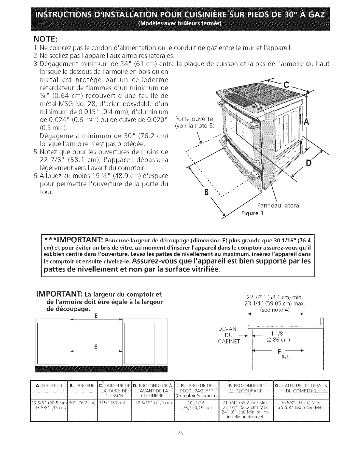
NOTE:
1.He coincez pas le cordon d'alimentation ou le conduit de gaz entre lemur et I'appareil.
2.Ne scellez pas I'appareil aux armoires lat_rales.
3.D_gagement minimum de 24" (61 cm) entre la plaque de cuisson et la has de I'armoire du haut
Iorsque le dessous de I'armoire en bois ou en
m@tal est prot@g@ par un celloderme
retardateur de flammes d'un minimum de
1/4" (0.64 cm) recouvert d'une feuille de
m@tal MSG No. 28, d'acier inoxydable d'un
minimum de 0.015" (0.4 mm), d'aluminium
de 0.024" (0.6 mm) ou de cuivre de 0.020"
(0.5 ram).
D@gagement minimum de 30" (76.2 cm)
Iorsque I'armoire n'est pas prot@g@e.
5. Notez que pour les ouvertures de moins de
22 7/8" (58.1 cm), I'appareil d@passera
I@g@rementvers I'avant du comptoir.
6.AIIouez au moins 19 1/4" (48.9 cm) d'espace
pour permettre I'ouverture de la porte du
four.
Porte ouverte
(voir la note 5)
÷÷
÷
°
A
Panneau lateral
Figure 1
***IMPORTANT: Pour une largeur de d_coupage (dimension E) plus grande que 30 1/16" (76.4
cm) et pour _viter un bris de vitre, au moment d'ins_rer I'appareil dans le comptoir assurez-vous qu'il
est bien centr_ dans I'ouverture. Levez les pattes de nivellement au maximum, ins_rez I'appareil dans
le comptoir et ensuite nivelez-le. Assurez-vous que I'appareil est bien support6 par les
pattes de nivellement et non par la surface vitrifiee.
IMPORTANT: La largeur du comptoir et
de J'armoire doit _tre egale & Ja Jargeur
de decoupage.
E
4b
E
22 7/8" (58.1 cm) rain.
23 I/4" (59.05 cm) max.
(see note 4)
DEVAN =
Du , t -- i '
CABINET (2.86 cm)
F_
Refl
A. HAUTEUR , B. LARGEUR C. LARGEUR DE
LA TABLE DE
• " CUISSON
35 5/8" (90.5 cr'n} 30" (76,2 cm} 31Y2" (80 cm}
36 5/8" (93 cm}
D. PRoFoNDEuR _
L!AVANT DE LA
CUISINIERE
28 5/16" (71,9 cm}
E. LARGEUR DE F. PROFONDEUR G. HAUTEUR DU DESSUS
DECOUPAGE _*_ DE D_.COUPAGE DE COMPTOIR
(Comptoir & armoire
30±1/16 21 3/4" (55,2 cm) Min. 36 5/8" (93 cm} Max.
(76,2±0,15 cm) 22 I/8" (56,2 cm} Max 35 5/8" (90.5 cm} Min.
24" (61 cm) Min. si I'on
installe un dosseret
25
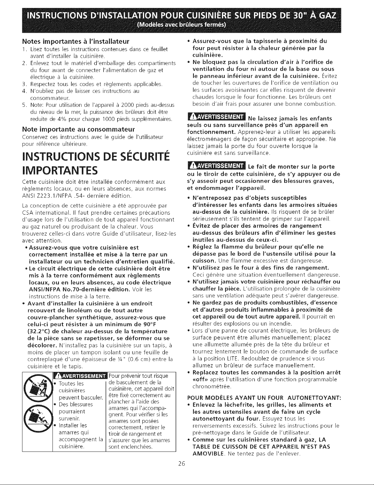
Notes irnportantes _ I'installateur
1. Lisez toutes les instructions contenues dans ce feuillet
avant d'installer la cuisiniere.
2. Enlevez tout le materiel d'emballage des compartiments
du four avant de connecter I'alimentation de gaz et
electrique a la cuisiniere.
3. Respectez tousles codes et reglements alaplicables.
4. N'oubliez pas de laisser ces instructions au
consommateur.
5. Note: Pour utilisation de I'appareil a 2000 laieds au-dessus
du niveau de la met, la puissance des br01eurs dolt _tre
reduite de 4% pour chaque 1000 pieds supplementaires.
Note irnportante au consornrnateur
Conservez ces instructions avec le guide de I'utilisateur
pour reference ulterieure.
INSTRUCTIONS DE SieCURITie
IMPORTANTES
Cette cuisiniere dolt _tre installee conformement aux
reglements Iocaux, ou en leurs absences, aux normes
ANSI Z223.1/NFPA .54- derniere edition.
La conception de cette cuisiniere a ete approuvee par
CSA international. II faut prendre certaines larecautions
d'usage Iors de I'utilisation de tout alapareil fonctionnant
au gaz naturel ou produisant de la chaleur. Vous
trouverez celles-ci dans votre Guide d'utilisateur, lisez-les
avec attention.
• Assurez-vous que votre cuisini_re est
correctement install_e et mise a la terre par un
installateur ou un technicien d'entretien qualifi_.
, Le circuit _lectrique de cette cuisiniere doit _tre
mis a la terre conform_ment aux reglements
Iocaux, ou en leurs absences, au code electrique
ANSI/NFPA No.70-derni_re edition. Voir les
instructions de mise a la terre.
• Avant d'installer la cuisiniere a un endroit
recouvert de linol&um ou de tout autre
couvre-plancher synthetique, assurez-vous que
celui-ci peut r_sister a un minimum de 90°F
(32.2°C) de chaleur au-dessus de la temperature
de la piece sans se rapetisser, se d_former ou se
decolorer. N'installez pas la cuisiniere sur un tapis,
moins de placer un tampon isolant ou une feuille de
contreplaque d'une epaisseur de ¼" (0.6 cm) entre la
cuisiniere et le tapis.
Toutes les
cuisinieres
peuvent basculer.
Des blessures
laourraient
survenir.
Installer les
amarres qui
accomlaagnent la
cuisiniere.
larevenir tout risque
de basculement de la
cuisiniere, cet alapareil dolt
_tre fixe correctement au
lalancher a I'aide des
amarres qui I'accomlaa-
ghent. Pour verifier si les
amarres sont laosees
correctement, retirer le
tiroir de rangement et
s'assurer que les amarres
sont enclenchees.
• Assurez-vous que la tapisserie a proximit_ du
four peut resister a la chaleur g_ner_e par la
cuisiniere.
• Ne bloquez pas la circulation d'air a l'orifice de
ventilation du four ni autour de la base ou sous
le panneau inf_rieur avant de la cuisiniere. Evitez
de toucher les ouvertures de I'orifice de ventilation ou
les surfaces avoisinantes car elles risquent de devenir
chaudes Iorsque le four fonctionne. Les br01eurs ont
besoin d'air frais pour assurer une bonne combustion.
Ne laissez jamais les enfants
seuls ou sans surveillance pres d'un appareil en
fonctionnement. Apprenez-leur a utiliser les alalaareils
electromenagers de faqon securitaire et alapropriee. Ne
laissez jamais la porte du four ouverte Iorsque la
cuisiniere est sans surveillance.
Le fait de monter sur la porte
ou le tiroir de cette cuisiniere, de s'y appuyer ou de
s'y asseoir peut occasionner des blessures graves,
et endommager I'appareil.
• N'entreposez pas d'objets susceptibles
d'int_resser les enfants dans les armoires situ_es
au-dessus de la cuisiniere. IIs risquent de se brOler
serieusement s'ils tentent de grimlaer sur I'appareil.
• Evitez de placer des armoires de rangement
au-dessus des br01eurs afin d'_liminer les gestes
inutiles au-dessus de ceux-ci.
• R_glez la flamme du br01eur pour qu'elle ne
d_passe pas le bord de I'ustensile utilis_ pour la
cuisson. Une flamme excessive est dangereuse.
• N'utilisez pas le four a des fins de rangement.
Ceci genere une situation eventuellement dangereuse.
• N'utilisez jamais votre cuisiniere pour r_chauffer ou
chauffer la piece. L'utilisation prolongee de la cuisiniere
sans une ventilation adequate laeut s'averer dangereuse.
• Ne gardez pas de produits combustibles, d'essence
et d'autres produits inflammables a proximit_ de
cet appareil ou de tout autre appareil. II laourrait en
resulter des explosions ou un incendie.
Lors d'une panne de courant electrique, les br01eurs de
surface peuvent _tre allumes manuellement; lalacez
une allumette allumee lares de la t_te du br01eur et
tournez lentement le bouton de commande de surface
la position LITE. Redoublez de prudence si vous
allumez un br01eur de surface manuellement.
• Replacez toutes les commandes a la position arr_t
_off_ alares I'utilisation d'une fonction programmable
chronometree.
POUR MODELESAYANTUN FOUR AUTONETTOYANT:
• Enlevez la lechefrite, les grilles, les aliments et
les autres ustensiles avant de faire un cycle
autonettoyant du four. Essuyez tousles
renversements excessifs. Suivez les instructions pour le
lar&nettoyage dans le Guide de I'utilisateur.
, Comme sur les cuisinieres standard a gaz, LA
TABLE DE CUISSON DE CET APPAREIL N'EST PAS
AMOVlBLE. Ne tentez laas de I'enlever.
26
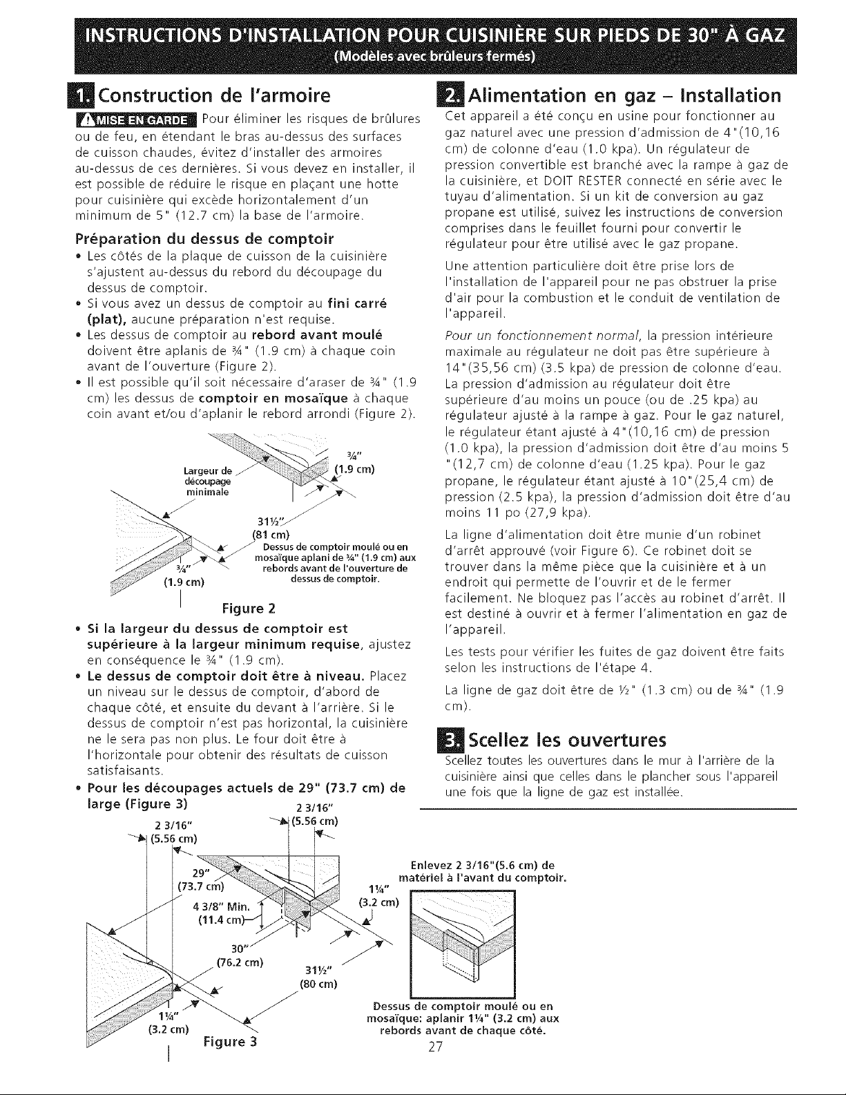
Construction de Varrnoire
Pour eliminer les risques de br01ures
ou de feu, en etendant le bras au-dessus des surfaces
de cuisson chaudes, evitez d'installer des armoires
au-dessus de ces dernieres. Si vous devez en installer, il
est possible de reduire le risque en plaqant une hotte
pour cuisiniere qui excede horizontalement d'un
minimum de 5" (12.7 cm) la base de I'armoire.
Preparation du dessus de comptoir
• Les c6tes de la plaque de cuisson de la cuisiniere
s'ajustent au-dessus du rebord du decoupage du
dessus de comptoir.
, Si vous avez un dessus de comptoir au fini carr_
(plat), aucune preparation n'est requise.
• Les dessus de comptoir au rebord avant moul_
doivent _tre aplanis de 3A" (1.9 cm) a chaque coin
avant de I'ouverture (Figure 2).
, II est )ossible qu'il soit necessaire d'araser de %" (1.9
cm) les dessus de comptoir en mosa'l'que a chaque
coin avant et/ou d'aplanir le rebord arrondi (Figure 2).
Larg
decoupage
(1.9 cm)
(81 cm)
J Dessus de comptoir moule ou en
mosaE'que aplani de %" (1.9 cm) aux
rebords avant de I'ouverture de
(1.9 cm) dessus de comptoir.
I Figure 2
. Si la largeur du dessus de comptoir est
sup_rieure a la largeur minimum requise, ajustez
en consequence le %" (1.9 cm).
• Le dessus de comptoir doit _tre a niveau. Placez
un niveau sur le dessus de comptoir, d'abord de
chaque c&te, et ensuite du devant a I'arriere. Si le
dessus de comptoir n'est pas horizontal, la cuisiniere
ne le sera pas non plus. Le four doit _tre
I'horizontale pour obtenir des resultats de cuisson
satisfaisants.
, Pour les d_coupages actuels de 29" (73.7 cm) de
large (Figure 3) 2 3/16"
2 3/16" _-J_t (5.56 cm)
(5.56 crn)
L
(3.2 cm)
I
Aiimentation en gaz- Installation
Cet appareil a ete con_u en usine pour fonctionner au
gaz naturel avec une pression d'admission de 4"(10,16
cm) de colonne d'eau (1.0 kpa). Un regulateur de
pression convertible est branche avec la rampe a gaz de
la cuisiniere, et DOlT RESTER connecte en serie avec le
tuyau d'alimentation. Si un kit de conversion au gaz
propane est utilise, suivez les instructions de conversion
comprises dans le feuillet fourni pour convertir le
regulateur pour _tre utilise avec le gaz propane.
Une attention particuliere doit _tre prise lots de
I'installation de I'appareil pour ne pas obstruer la prise
d'air pour la combustion et le conduit de ventilation de
I'appareil.
Pour un fonctionnement norma/, la pression interieure
maximale au regulateur ne doit pas _tre superieure
14"(35,56 cm) (3.5 kpa) de pression de colonne d'eau.
La pression d'admission au regulateur doit _tre
superieure d'au moins un pouce (ou de .25 kpa) au
regulateur ajuste a la rampe a gaz. Pour le gaz naturel,
le regulateur etant ajuste a 4"(10,16 cm) de pression
(1.0 kpa), la pression d'admission doit _tre d'au moins 5
"(12,7 cm) de colonne d'eau (1.25 kpa). Pour le gaz
propane, le regulateur etant ajuste a 10" (25,4 cm) de
pression (2.5 kpa), la pression d'admission doit _tre d'au
moins 11 po (27,9 kpa).
La ligne d'alimentation doit _tre munie d'un robinet
d'arr_t approuve (voir Figure 6). Ce robinet doit se
trouver darts la m_me piece que la cuisiniere eta un
endroit qui permette de I'ouvrir et de le fermer
facilement. Ne bloquez pas I'acces au robinet d'arr_t. II
est destine a ouvrir eta fermer I'alimentation en gaz de
I'appareil.
Les tests pour verifier les fuites de gaz doivent _tre faits
selon les instructions de I'etape 4.
La ligne de gaz doit _tre de _/_" (1.3 cm) ou de %" (1.9
cm).
JScellez les ouvertures
Scellez toutes les ouvertures dans le mur a I'arriere de la
cuisiniere ainsi que celles darts le plancher sous I'appareil
une fois que la ligne de gaz est installee.
Enlevez 2 3116"(5.6 crn) de
materiel a I'avant du comptoir.
I_ "
(3.2 cm)
Dessus de comptoir moule ou en
mosaTque: aplanir 11A'' (3.2 cm) aux
rebords avant de chaque cote.
27
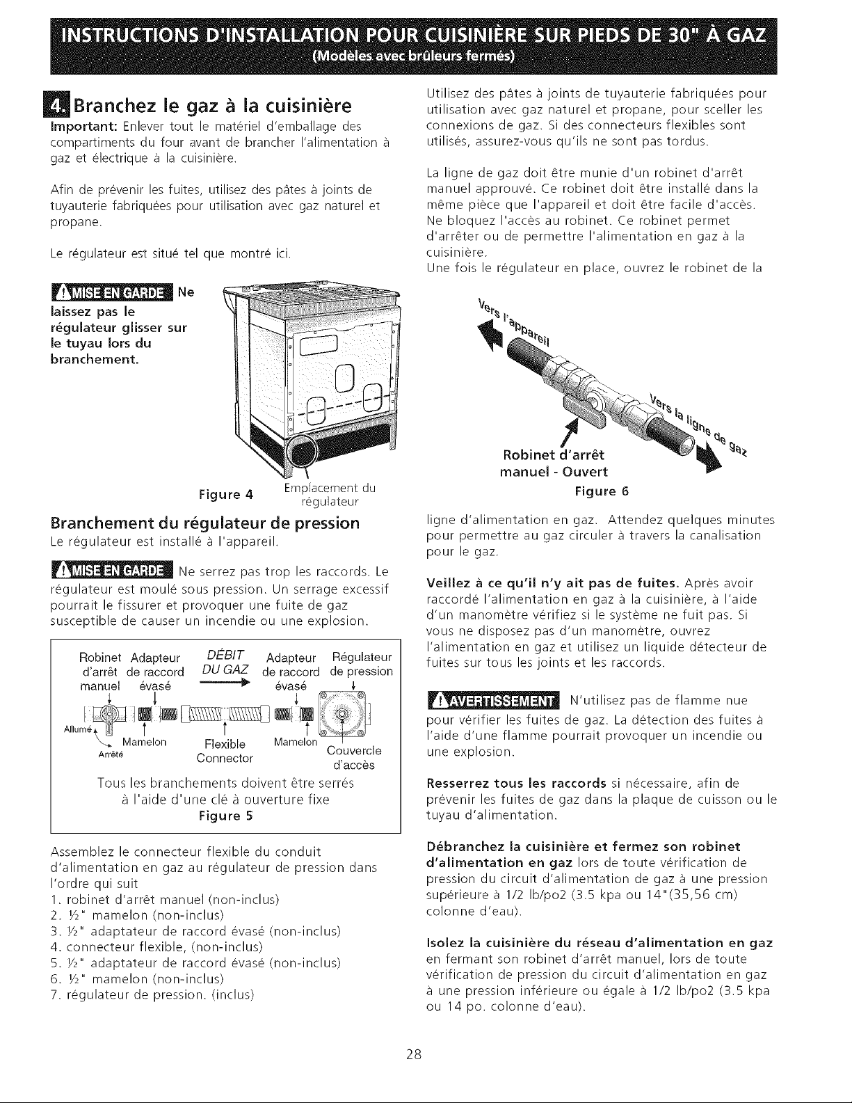
[! Branchez le gaz a la cuisiniere
Important: Enlever tout le materiel d'emballage des
compartiments du four avant de brancher I'alimentation a
gaz et electrique a la cuisiniere.
Afin de prevenir les fuites, utilisez des pates a joints de
tuyauterie fabriquees pour utilisation avec gaz naturel et
propane.
Le regulateur est situe tel que montre ici.
Ne
laissez pas le
r&gulateur glisser sur
le tuyau Iors du
branchement.
Figure 4 Emplacement du
regulateur
Branchement du regulateur de pression
Le regulateur est installe a I'appareil.
Ne serrez pas trop les raccords. Le
regulateur est moule sous pression. Un serrage excessif
pourrait le fissurer et provoquer une fuite de gaz
susceptible de causer un incendie ou une explosion.
Robinet Adapteur DEBIT Adapteur Regulateur
d'arr6t de raccord DU GAZ de raccord de pression
manuel 6vase _ _vas6
Mamelon Flexible Mamelon
Couvercle
Arr&t6 Connector
d'acces
Tousles branchements doivent 6tre serr_s
I'aide d'une cl_ a ouverture fixe
Figure 5
Utilisez des pates _ joints de tuyauterie fabriquees pour
utilisation avec gaz naturel et propane, pour sceller les
connexions de gaz. Si des connecteurs flexibles sont
utilises, assurez-vous qu'ils ne sont pas tordus.
La ligne de gaz doit _tre munie d'un robinet d'arr_t
manuel approuve. Ce robinet doit _tre installe darts la
m_me piece que I'appareil et doit _tre facile d'acces.
Ne bloquez I'acces au robinet. Ce robinet permet
d'arr_ter ou de permettre I'alimentation en gaz a la
cuisiniere.
Une fois le regulateur en place, ouvrez le robinet de la
Robinet d'arr6t
manuel - Ouvert
Figure 6
ligne d'alimentation en gaz. Attendez quelques minutes
pour permettre au gaz circuler a travers la canalisation
pour le gaz.
Veillez ace qu'il n'y ait pas de fuites. Apres avoir
raccorde I'alimentation en gaz a la cuisiniere, a I'aide
d'un manometre verifiez si le systeme ne fuit pas. Si
vous ne disposez pas d'un manometre, ouvrez
I'alimentation en gaz et utilisez un liquide detecteur de
fuites sur tous les joints et les raccords.
N'utilisez pas de flamme nue
pour verifier les fuites de gaz. La detection des fuites
I'aide d'une flamme pourrait provoquer un incendie ou
une explosion.
Resserrez tousles raccords si necessaire, afin de
prevenir les fuites de gaz dans la plaque de cuisson ou le
tuyau d'alimentation.
Assemblez le connecteur flexible du conduit
d'alimentation en gaz au regulateur de pression dans
I'ordre qui suit
1. robinet d'arret manuel (non-inclus)
2. Y2" mamelon (non-inclus)
3. Y2" adaptateur de raccord evase (non-inclus)
4. connecteur flexible, (non-inclus)
5. Y2" adaptateur de raccord evase (non-inclus)
6. Y2" mamelon (non-inclus)
7. regulateur de pression. (inclus)
D_branchez la cuisiniere et fermez son robinet
d'alimentation en gaz lots de toute verification de
pression du circuit d'alimentation de gaz a une pression
superieure a 1/2 Ib/po2 (3.5 kpa ou 14"(35,56 cm)
colonne d'eau).
Isolez la cuisiniere du r_seau d'alimentation en gaz
en fermant son robinet d'arr_t manuel, Iors de toute
verification de pression du circuit d'alimentation en gaz
une pression inferieure ou egale a 1/2 Ib/po2 (3.5 kpa
ou 14 pc. colonne d'eau).
28
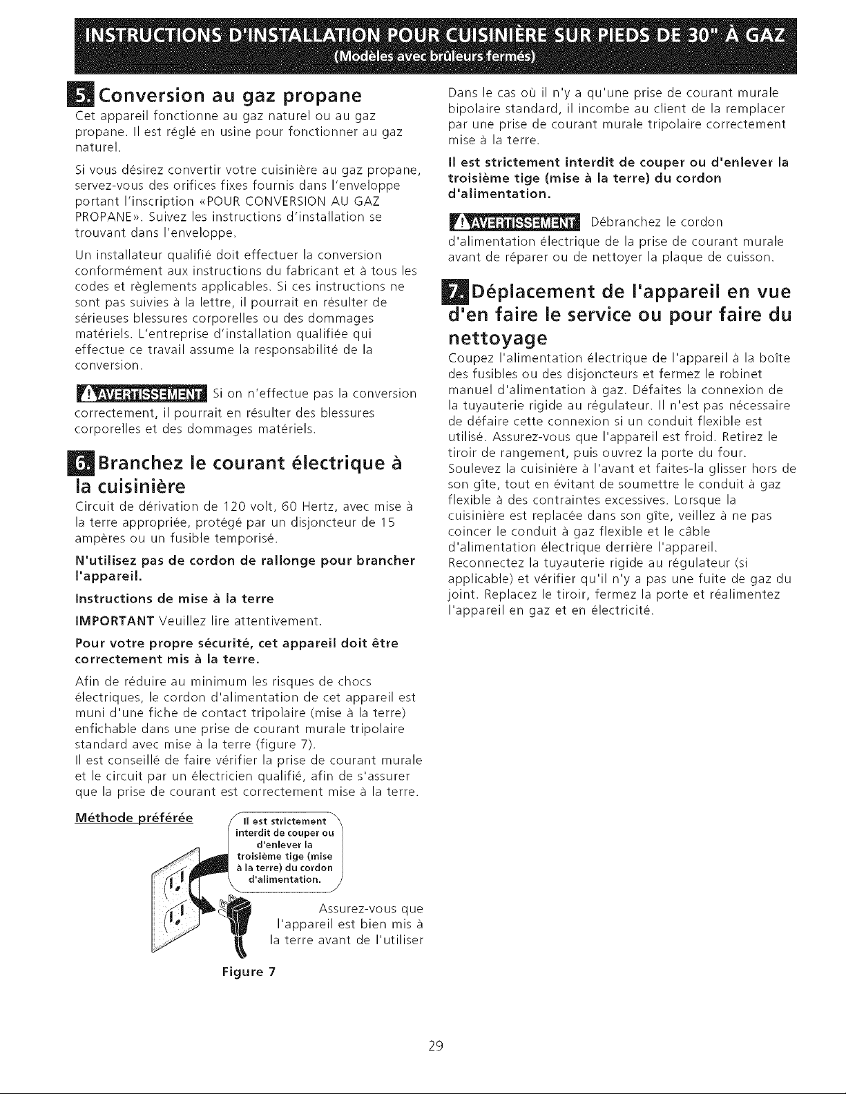
Conversion au gaz propane
Cet appareil fonctionne au gaz naturel ou au gaz
propane. II est regle en usine pour fonctionner au gaz
naturel.
Si vous desirez convertir votre cuisiniere au gaz propane,
servez-vous des orifices fixes fournis dans I'enveloppe
portant I'inscription <<POURCONVERSION AU GAZ
PROPANE>>. Suivez les instructions d'installation se
trouvant dans I'enveloppe.
Un installateur qualifie doit effectuer la conversion
conformement aux instructions du fabricant eta tousles
codes et reglements applicables. Si ces instructions ne
sont pas suivies a la lettre, il pourrait en resulter de
serieuses blessures corporelles ou des dommages
materiels. L'entreprise d'installation qualifiee qui
effectue ce travail assume la responsabilite de la
conversion.
Si on n'effectue pas la conversion
correctement, il pourrait en resulter des blessures
corporelles et des dommages materiels.
Branchez le courant lectrique
la cuisiniere
Circuit de derivation de 120 volt, 60 Hertz, avec mise
la terre appropriee, protege par un disjoncteur de 15
amperes ou un fusible temporise.
N'utilisez pas de cordon de rallonge pour brancher
I'appareil.
Instructions de raise a la terre
IMPORTANT Veuillez lire attentivement.
Dans le cas ou il n'y a qu'une prise de courant murale
bipolaire standard, il incombe au client de la remplacer
par une prise de courant murale tripolaire correctement
mise a la terre.
II est strictement interdit de couper ou d'enlever la
troisi_me tige (raise a la terre) du cordon
d'alimentation.
Debranchez le cordon
d'alimentation electrique de la prise de courant murale
avant de reparer ou de nettoyer la plaque de cuisson.
D placernent de I'appareil en vue
d'en faire le service ou pour faire du
nettoyage
Coupez I'alimentation electrique de I'appareil a la boite
des fusibles ou des disjoncteurs et fermez le robinet
manuel d'alimentation a gaz. Defaites la connexion de
la tuyauterie rigide au regulateur. II n'est pas necessaire
de defaire cette connexion si un conduit flexible est
utilise. Assurez-vous que I'appareil est froid. Retirez le
tiroir de rangement, puis ouvrez la porte du four.
Soulevez la cuisiniere a I'avant et faites-la glisser hors de
son g_te, tout en evitant de soumettre le conduit a gaz
flexible a des contraintes excessives. Lorsque la
cuisiniere est replacee dans son g_te, veillez a ne pas
coincer le conduit a gaz flexible et le c_fible
d'alimentation electrique derriere I'appareil.
Reconnectez la tuyauterie rigide au regulateur (si
applicable) et verifier qu'il n'y a pas une fuite de gaz du
joint. Replacez le tiroir, fermez la porte et realimentez
I'appareil en gaz et en electricite.
Pour votre propre s_curit_, cet appareil dolt _tre
correctement mis a la terre.
Afin de reduire au minimum les risques de chocs
electriques, le cordon d'alimentation de cet appareil est
muni d'une fiche de contact tripolaire (raise a la terre)
enfichable dans une prise de courant murale tripolaire
standard avec raise a la terre (figure 7).
II est conseille de faire verifier la prise de courant murale
et le circuit par un electricien qualifie, afin de s'assurer
que la prise de courant est correctement raise a la terre.
M_thode pr_f_r_e SIIest strictement
interdit de couper ou
d'enlever la
troisieme tige (raise
la terre) du cordon
d'alimentation. /
Assurez-vous que
I'appareil est bien mis a
la terre avant de I'utiliser
Figure 7
29
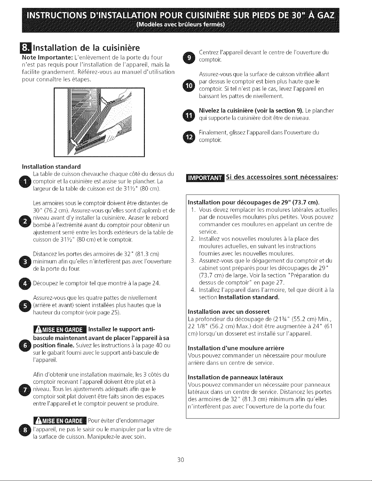
installation de la cuisiniere
Note Importante: L'enlSvement de la porte du four
n'est pas requis pour I'installation de I'appareil, mais la
facilite grandement. RefSrez-vous au manuel d'utilisation
pour connaTtre les Stapes.
Centrez I'appareil devant le centre de I'ouverture du
comptoir.
Assurez-vous que la surface de cuisson vitrifiSe allant
par dessus le comptoir est bien plus haute que le
comptoir. Si tel n'est pas le cas, levez I'appareil en
baissant les pattes de nivellement.
Nivelez la cuisiniere (voir la section 9). Le plancher
qui supporte la cuisiniSredolt Stre de niveau.
Finalement, glissez I'appareil dans I'ouverture du
comptoir.
installation standard
Latable de cuisson chevauche chaque c6tS du dessusdu
)comptoir et la cuisiniSre est assisesur le plancher. La
largeur de la table de cuisson est de 31Y2" (80 cm).
Lesarmoires sous le comptoir doivent Stre distantes de
30" (76.2 cm). Assurez-vous qu'elles sont d'aplomb et de
O niveau avant d'y installer la cuisiniSre. Araser le rebord
bombs a I'extrSmit_ avant du comptoir pour obtenir un
ajustement serr_ entre les bords extSrieurs de la table de
cuisson de 311/2" (80 cm) et le comptoir.
Distancez les portes des armoires de 32" (81.3 cm)
minimum afin qu'elles n'interfSrent pas avec I'ouverture
de la porte du four.
, DScoupez le comptoir tel que montrS a la page 24.
Assurez-vous que lesquatre pattes de nivellement
I (arriSre et avant) soient installees plus hautes que la
hauteur du comptoir (voir page 25).
Installez le support anti-
bascule maintenant avant de placer l'appareil a sa
pposition finale. Suivez les instructions _ la page 40 ou
sur le gabarit fourni avec le support anti-bascule de
I'appareil.
Afin d'obtenir une installation maximale, les 3 c6tSs du
comptoir recevant I'appareil doivent @re plat et
niveau. Tousles ajustements adSquats afin que le
comptoir soit plat doivent Stre faits sinon des espaces
entre I'appareil et le comptoir peuvent se produire.
Pour Sviterd'endommager
, I'appareil, ne pas le saisir ou le manipuler par la vitre de
la surface de cuisson. Manipulez-le avec soin.
Si des accessoires sont necessaires:
installation pour d_coupages de 29" (73.7 cm).
I. Vous devez remplacer les moulures laterales actuelles
par de nouvelles moulures plus petites. Vous pouvez
commander ces moulures en appelant un centre de
service.
2. Installez vos nouvelles moulures a la place des
moulures actuelles, en suivant les instructions
fournies avec les nouvelles moulures.
3. Assurez-vous que le degagement du comptoir et du
cabinet sont pr@arSs pour les dScoupages de 29"
(73.7 cm) de large. Voir la section "Pr@aration du
dessus de comptoir" en page 27.
4. Installez I'appareil dans I'armoire, tel que dScrit a la
section installation standard.
installation avec un dosseret
La profondeur du dScoupage de (213A'' (55.2 cm) Min.,
22 1/8" (56.2 cm) Max.) dolt Stre augmentSe a 24" (61
cm) Iorsqu'un dosseret est installs sur I'appareil.
installation d'une moulure arri_re
Vous pouvez commander un necessaire pour moulure
arriSre dans un centre de service.
installation de panneaux lat_raux
Vous pouvez commander un nScessaire pour panneaux
lateraux dans un centre de service. Distancez les portes
des armoires de 32" (81.3 cm) minimum afin qu'elles
n'interfSrent pas avec I'ouverture de la porte du four.
30
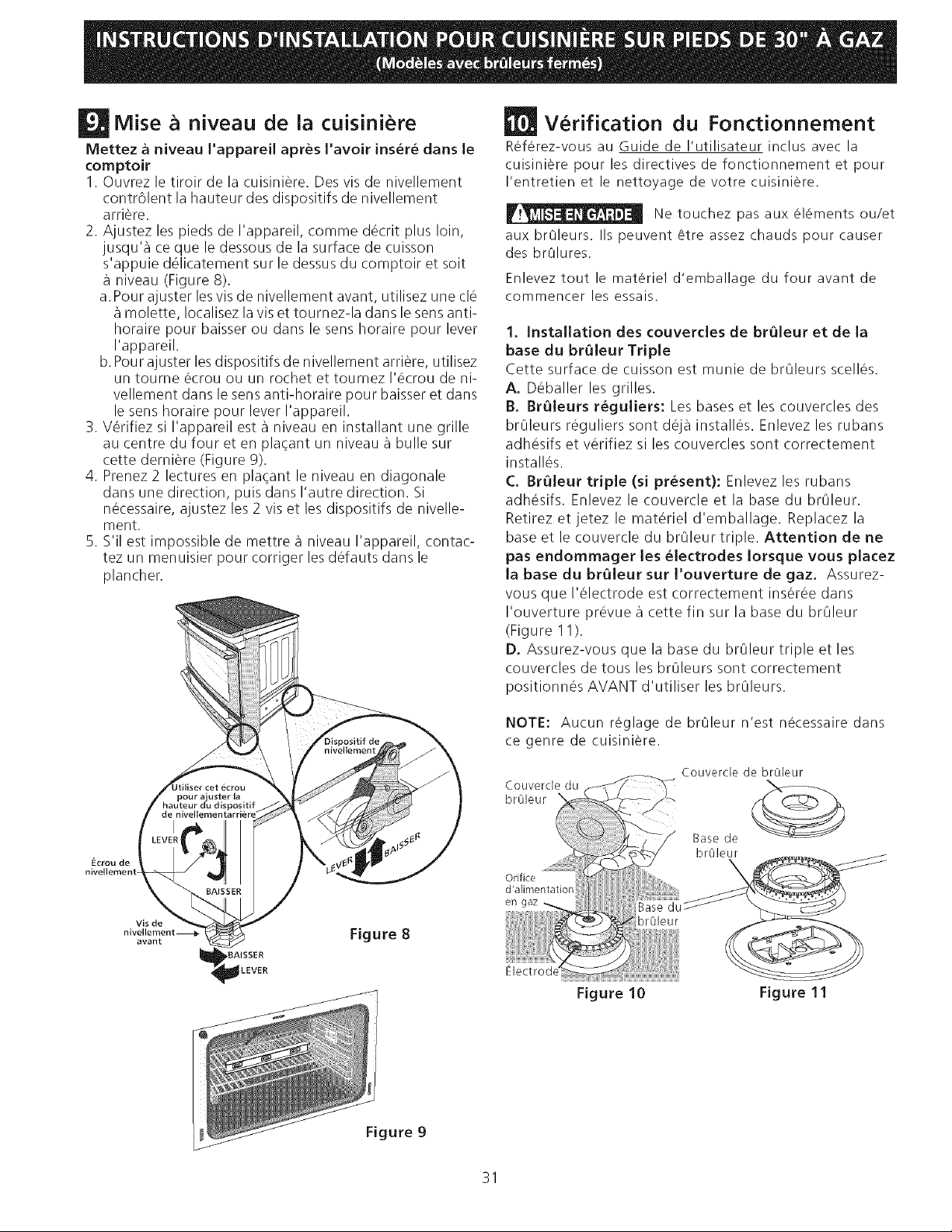
Mise a niveau de la cuisiniere
Mettez a niveau I'appareil apres I'avoir ins&r& dans le
comptoir
1. Ouvrez le tiroir de la cuisini_re. Des vis de nivellement
contr61ent la hauteur des dispositifs de nivellement
arri_re.
2. Ajustez les pieds de I'appareil, comme d_crit plus loin,
jusqu'a ce que le dessous de la surface de cuisson
s'appuie d_licatement sur le dessus du comptoir et soit
niveau (Figure 8).
a. Pour ajuster lesvis de nivellement avant, utilisez une cl_
molette, Iocalisez la vis et tournez-la dans le sens anti-
horaire pour baisser ou dans le sens horaire pour lever
I'appareil.
b. Pour ajuster les dispositifs de nivellement arriere, utilisez
un tourne ecrou ou un rochet et tournez I'_crou de ni-
vellement dans le sens anti-horaire pour baisser et dans
le sens horaire pour lever I'appareil.
3. Verifiez si I'appareil est a niveau en installant une grille
au centre du four et en plat;ant un niveau a bulle sur
cette derniere (Figure 9).
4. Prenez 2 lectures en plat;ant le niveau en diagonale
dans une direction, puis dans I'autre direction. Si
necessaire, ajustez les 2 vis et les dispositifs de nivelle-
ment.
5. S'il est impossible de mettre a niveau I'appareil, contac-
tez un menuisier pour corriger les d_fauts dans le
plancher.
uuu_ l_L
pour a'uster la
_hauteur _lul dispositif
/J de[ nivellemen
Ecrou de
nivellement
Vis de
nivellement _
avant
Figure 8
LEVER
Verification du Fonctionnement
Referez-vous au Guide de I'utilisateur inclus avec la
cuisiniere pour les directives de fonctionnement et pour
I'entretien et le nettoyage de votre cuisiniere.
Ne touchez pas aux elements ou/et
aux brOleurs. IIs peuvent Ctre assez chauds pour causer
des brOlures,
Enlevez tout le materiel d'emballage du four avant de
commencer les essais.
1. Installation des couvercles de br_leur et de la
base du br_leur Triple
Cette surface de cuisson est munie de brOleurs scell_s.
A. D_baller les grilles.
13. Br_leurs r_guliers: Les bases et les couvercles des
brOleurs reguliers sont deja install_s. Enlevez les rubans
adh_sifs et v_rifiez si les couvercles sont correctement
install_s.
C. BrQleur triple (si present): Enlevez les rubans
adh_sifs. Enlevez le couvercle et la base du brOleur.
Retirez et jetez le materiel d'emballage. Replacez la
base et le couvercle du brOleur triple. Attention de ne
pas endommager les _lectrodes Iorsque vous piacez
labasedubr_leursurl'ouverturedegaz. Assurez-
vous que I'_lectrode est correctement ins_r_e dans
I'ouverture pr_vue a cette fin sur la base du br01eur
(Figure 1I).
D. Assurez-vous que la base du br01eur triple et les
couvercles de tous les br01eurs sont correctement
positionnes AVANT d'utiliser les br01eurs.
NOTE: Aucun reglage de brOleur n'est necessaire dans
ce genre de cuisiniere.
Couverde du
brOleur
Orifice
d'alimentation
en gaz
brOleur
Electrode'
Figure 10
Couvercle de br01eur
Base de
br01eur
\
Figure 11
Figure 9
31
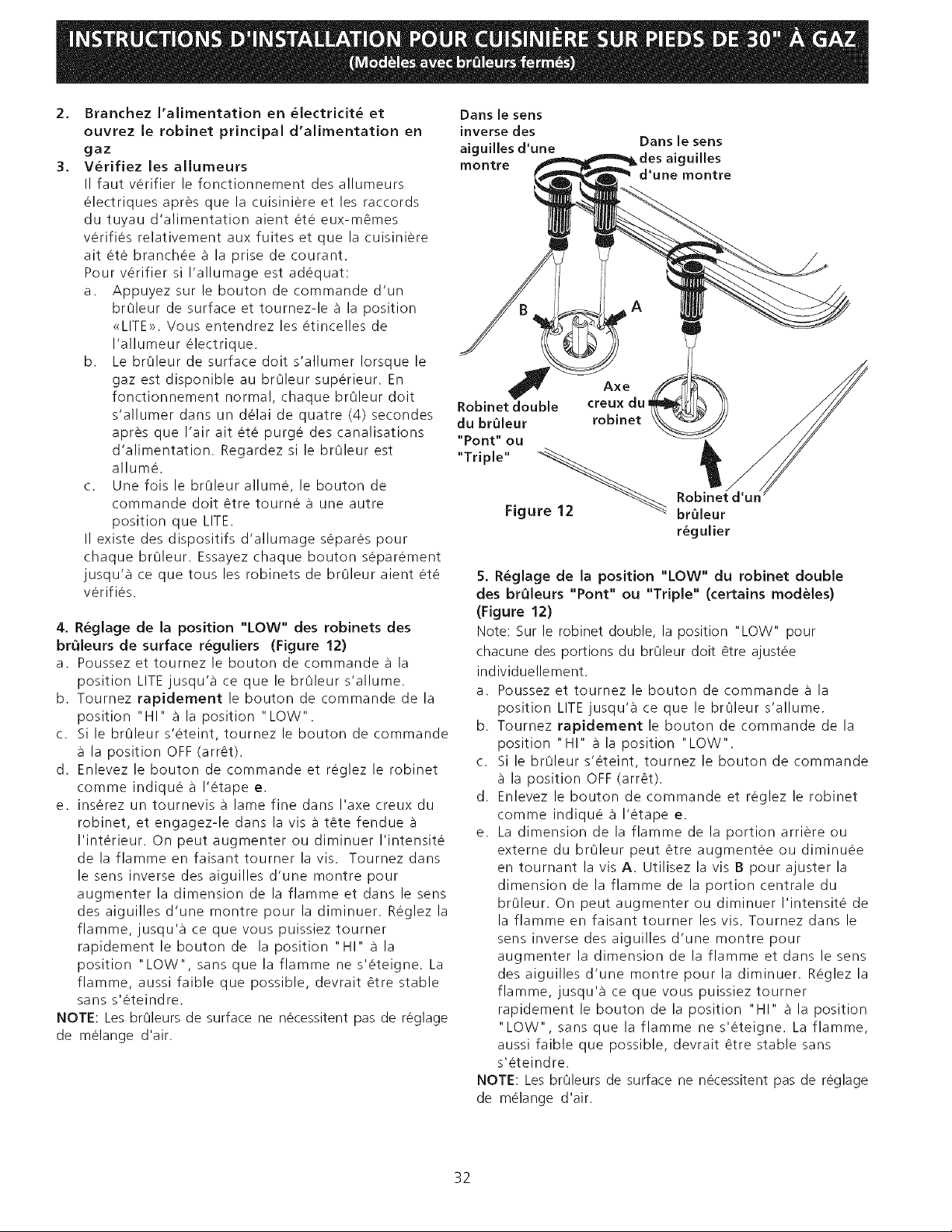
2,
3,
Branchez I'alimentation en _lectricit_ et
ouvrez le robinet principal d'alimentation en
gaz
V_rifiez les allumeurs
II faut verifier le fonctionnement des allumeurs
electriques apres que la cuisiniere et les raccords
du tuyau d'alimentation aient ete eux-m_mes
verifies relativement aux fuites et que la cuisiniere
ait ete branchee a la prise de courant.
Pour verifier si I'allumage est adequat:
a. Appuyez sur le bouton de commande d'un
brOleur de surface et tournez-le a la position
<<LITE>>,Vous entendrez les etincelles de
I'allumeur electrique.
b. Le brOleur de surface dolt s'allumer Iorsque le
gaz est disponible au brOleur superieur. En
fonctionnement normal, chaque brOleur dolt
s'allumer dans un delai de quatre (4) secondes
apres que I'air ait ete purge des canalisations
d'alimentation. Regardez si le brOleur est
allume.
c. Une fois le brOleur allume, le bouton de
commande dolt _tre tourne a une autre
position que LITE.
II existe des dispositifs d'allumage separes pour
chaque brOleur. Essayez chaque bouton separement
jusqu'a ce que tousles robinets de brOleur aient ete
verifies.
4. R_glage de la position "LOW" des robinets des
brQleurs de surface r_guliers (Figure 12)
a. Poussez et tournez le bouton de commande a la
position LITE jusqu'a ce que le brOleur s'allume.
b. Tournez rapidement le bouton de commande de la
position "HI" a la position "LOW".
c. Si le brOleur s'eteint, tournez le bouton de commande
la position OFF (arr_t).
d. Enlevez le bouton de commande et reglez le robinet
comme indique a I'etape e.
e. inserez un tournevis a lame fine dans I'axe creux du
robinet, et engagez-le dans la visa t6te fendue
I'interieur. On peut augmenter ou diminuer I'intensite
de la flamme en faisanttourner la vis. Tournez dans
le sens inverse des aiguilles d'une montre pour
augmenter la dimension de la flamme et dans le sens
des aiguilles d'une montre pour la diminuer. Reglez la
flamme, jusqu'a ce que vous puissiez tourner
rapidement le bouton de la position "HI" a la
position "LOW", sans que la flamme ne s'eteigne. La
flamme, aussi faible que possible, devrait _tre stable
sans s'eteindre.
NOTE: Les br01eurs de surface ne necessitent pas de reglage
de melange d'air.
Dans le sens
inverse des
aiguilles d'une Dans le sens
iuilles
rnontre
d'une rnontre
J Axe
Robinet double creux du_
du br61eur robinet
"Pont" ou
"Triple"
Figure 12
br61eur
r_gulier
5. R_glage de la position "LOW" du robinet double
des brQleurs "Pont" ou "Triple" (certains modeles)
(Figure 12)
Note: Sur le robinet double, la position "LOW" pour
chacune des portions du brOleur dolt _tre ajustee
individuellement.
a. Poussez et tournez le bouton de commande a la
position LITE jusqu'a ce que le brOleur s'allume.
b. Tournez rapidement le bouton de commande de la
position "HI" a la position "LOW".
c. Si le brOleur s'eteint, tournez le bouton de commande
la position OFF (arr_t).
d. Enlevez le bouton de commande et reglez le robinet
comme indique a I'etape e.
e. La dimension de la flamme de la portion arriere ou
externe du brOleur peut _tre augmentee ou diminuee
en tournant la vis A. Utilisez la vis B pour ajuster la
dimension de la flamme de la portion centrale du
brOleur. On peut augmenter ou diminuer I'intensite de
la flamme en faisant tourner les vis. Tournez dans le
sens inverse des aiguilles d'une montre pour
augmenter la dimension de la flamme et dans le sens
des aiguilles d'une montre pour la diminuer. Reglez la
flamme, jusqu'a ce que vous puissiez tourner
rapidement le bouton de la position "HI" a la position
"LOW", sans que la flamme ne s'eteigne. La flamme,
aussi faible que possible, devrait _tre stable sans
s'eteindre.
NOTE: Les br01eurs de surface ne necessitent pas de reglage
de melange d'air.
32
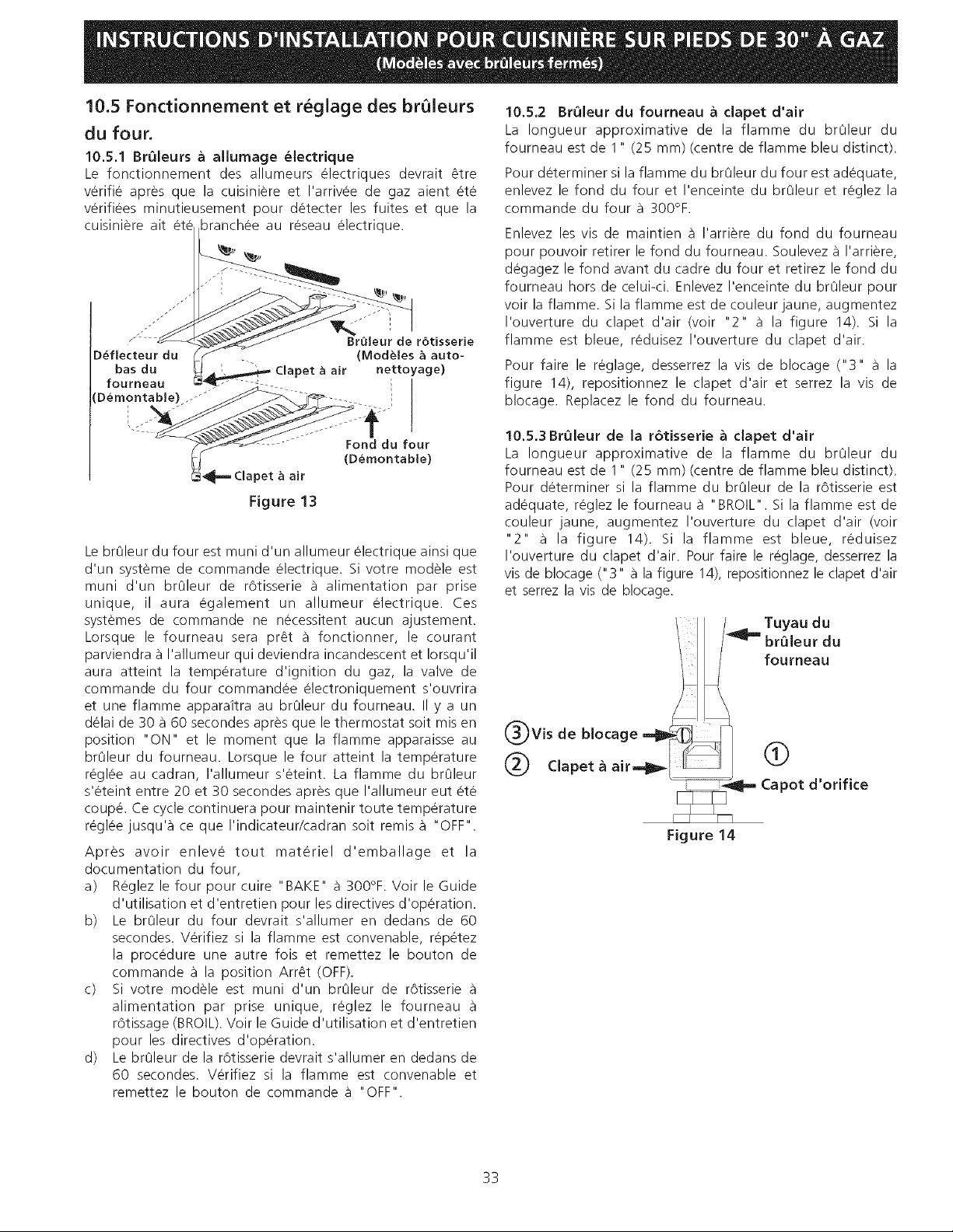
10.5 Fonctionnement et reglage des br leurs
du four.
10.5.1 BrQleurs & allumage _lectrique
Le fonctionnement des allumeurs electriques devrait _tre
verifie apres que la cuisiniere et I'arrivee de gaz aient ete
verifiees minutieusement pour detecter les fuites et que la
cuisiniere ait branchee au reseau electrique.
j_
" BrQleur de rotisserie
D_flecteur du (ModUles _ auto-
bas du )et a air nettoyage)
fourneau
Figure 13
Le br01eur du four est muni d'un allumeur electrique atnsi que
d'un systeme de commande electrique. Si votre modele est
muni d'un br01eur de rotisserie a alimentation par prise
unique, il aura egalement un allumeur electrique. Ces
systemes de commande ne necessitent aucun ajustement.
Lorsque le fourneau sera pr_t a fonctionner, le courant
parviendra _ I'allumeur qui deviendra incandescent et Iorsqu'il
aura atteint la temperature d'ignition du gaz, la valve de
commande du four commandee electroniquement s'ouvrira
et une flamme apparaitra au br01eur du fourneau. II y a un
delai de 30 a 60 secondes apres que le thermostat soit mis en
position "ON" et le moment que la flamme apparaisse au
br01eur du fourneau. Lorsque le four atteint la temperature
reglee au cadran, I'allumeur s'eteint. La flamme du br01eur
s'eteint entre 20 et 30 secondes apres que I'allumeur eut ete
coupe. Ce cycle continuera pour maintenir toute temperature
reglee jusqu'a ce que I'indicateur/cadran soit remis a "OFF".
Apres avoir enleve tout materiel d'emballage et la
documentation du four,
a) Reglez le four pour cuire "BAKE" a 300°F. Voir le Guide
d'utilisation et d'entretien pour les directives d'operation.
b) Le br01eur du four devrait s'allumer en dedans de 60
secondes. Verifiez si la flamme est convenable, repetez
la procedure une autre fois et remettez le bouton de
commande a la position Arr_t (OFF).
c) Si votre modele est muni d'un br01eur de rotisserie
alimentation par prise unique, reglez le fourneau
rOtissage (BROIL). Voir le Guide d'utilisation et d'entretien
pour les directives d'operation.
d) Le br01eur de la rotisserie devrait s'allumer en dedans de
60 secondes. Verifiez si la flamme est convenable et
remettez le bouton de commande a "OFF".
10.5.2 BrOleur du fourneau a clapet d'air
La Iongueur approximative de la flamme du br01eur du
fourneau est de 1" (25 mm) (centre de flamme bleu distinct).
Pour determiner si la flamme du br01eur du four est adequate,
enlevez le fond du four et I'enceinte du br01eur et reglez la
commande du four a 300°F.
Enlevez les vis de maintien a I'arriere du fond du fourneau
pour pouvoir retirer le fond du fourneau. Soulevez a I'arriere,
degagez le fond avant du cadre du four et retirez le fond du
fourneau hors de celui-ci. Enlevez I'enceinte du br01eur pour
voir la flamme. Si la flamme est de couleur jaune, augmentez
I'ouverture du clapet d'air (voir "2" a la figure 14). Si la
flamme est bleue, reduisez I'ouverture du clapet d'air.
Pour faire le reglage, desserrez la vis de blocage ("3" a la
figure 14), repositionnez le clapet d'air et serrez la vis de
blocage. Replacez le fond du fourneau.
lO.5.3BrOleur de la r6tisserie a clapet d'air
La Iongueur approximative de la flamme du br01eur du
fourneau est de 1" (25 mm) (centre de flamme bleu distinct).
Pour determiner si la flamme du br01eur de la rotisserie est
adequate, reglez le fourneau a "BROIL". Si la flamme est de
couleur jaune, augmentez I'ouverture du clapet d'air (voir
"2" a la figure 14). Si la flamme est bleue, reduisez
I'ouverture du clapet d'air. Pour faire le reglage, desserrez la
vis de blocage ("3" a la figure 14), repositionnez le clapet d'air
et serrez la vis de blocage.
/ fouroeau
(_)Vis de blocage _-_
(_ Clapet_air--l_ I_-_ ii ,
II-- Capot d orifice
Figure 14
33
Lorsque tous les raccords sont termM_s
Verifiez que toutes les commandes sont en position d'arret
(OFF).
Assurez-vous que la circulation d'air de combustion et de
ventilation a la cuisiniere n'est pas obstruee.
Emplacement des num_ros de module et de
serie
La plaque signaletique est situee sur le chassis avant du
four, derriere la porte du four (certains modeles) ou sur
le c6te du tiroir (certains modeles).
Lorsque vous commandez des pieces ou pour toute
demande de renseignements au sujet de votre cuisiniere,
assurez-vous de toujours inclure les numeros de modele
et de serie et un numero de lot ou une lettre de la
plaque signaletique de votre cuisiniere.
La plaque signaletique vous donne egalement la
capacite des brOleurs, le type de carburant et la pression
laquelle la cuisiniere a ete reglee au moment de
I'expedition.
Avant d'appeler le service d'entretien
Revisez la liste de verifications preventives et les
instructions d'operation darts votre Guide de I'utilisateur.
Vous sauverez probablement du temps et de I'argent.
La liste contient les evenements ordinaires qui ne
resultent pas de defectuosites dans le materiel ou la
fabrication de cet appareil.
Referez-vous a votre Guide de I'utilisateur pour les numeros
de telephone pour nous rejoindre.
34
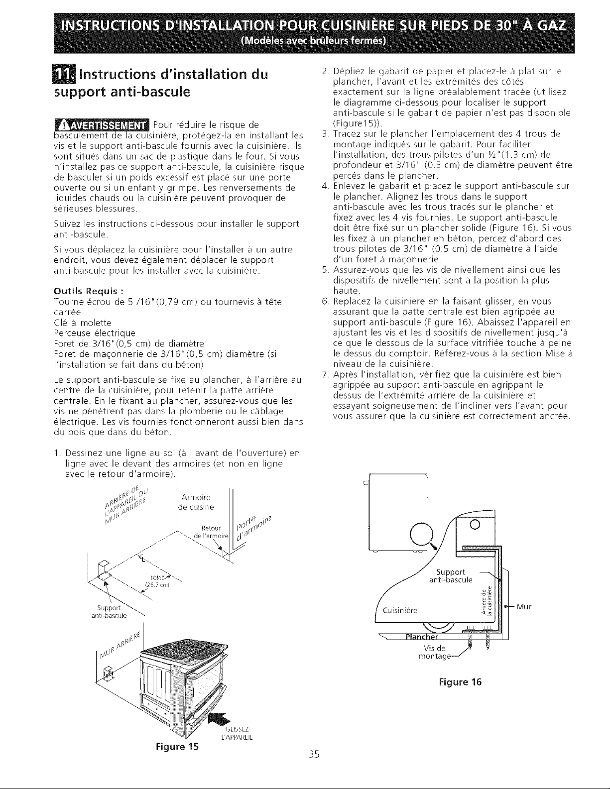
instructions dqnstallation du
support anti-bascule
Pour reduire le risque de
basculement de la cuisiniere, protegez-la en installant les
vis et le support anti-bascule fournis avec la cuisiniere. IIs
sont situes clans un sac de plastique dans le four. Si vous
n'installez pas ce support anti-bascule, la cuisiniere risque
de basculer si un poids excessif est place sur une porte
ouverte ou si un enfant y grimpe. Les renversements de
liquides chauds ou la cuisiniere peuvent provoquer de
serieuses blessures.
Suivez les instructions ci-dessous pour installer le support
anti-bascule.
Si vous deplacez la cuisiniere pour I'installer a un autre
endroit, vous devez egalement deplacer le support
anti-bascule pour les installer avec la cuisiniere.
Outils Requis :
Tourne ecrou de 5/16"(0,79 cm) ou tournevis a tate
carree
Cle _ molette
Perceuse electrique
Foret de 3/16"(0,5 cm) de diametre
Foret de maqonnerie de 3/16"(0,5 cm) diametre (si
I'installation se fait clans du baton)
Le support anti-bascule se fixe au plancher, a I'arriere au
centre de la cuisiniere, pour retenir la patte arriere
centrale. En le fixant au plancher, assurez-vous que les
vis ne penatrent pas clans la plomberie ou le c_blage
electrique. Les vis fournies fonctionneront aussi bien dans
du bois que darts du baton.
2. Depliez le gabarit de papier et placez-le a plat sur le
plancher, I'avant et les extr6mites des c6tes
exactement sur la ligne prealablement tracee (utilisez
le diagramme ci-dessous pour Iocaliser le support
anti-bascule si le gabarit de papier n'est pas disponible
(Figure1 5)).
3. Tracez sur le plancher I'emplacement des 4 trous de
montage indiques sur le gabarit. Pour faciliter
I'installation, des trous pilotes d'un Y2"(1.3 cm) de
profondeur et 3/16" (0.5 cm) de diametre peuvent 4tre
perces darts le plancher.
4. Enlevez le gabarit et placez le support anti-bascule sur
le plancher. Alignez les trous dans le support
anti-bascule avec les trous traces sur le plancher et
fixez avec les 4 vis fournies. Le support anti-bascule
doit atre fixe sur un plancher solide (Figure 16). Si vous
les fixez a un plancher en baton, percez d'abord des
trous pilotes de 3/16" (0.5 cm) de diametre a I'aide
d'un foret a maqonnerie.
5. Assurez-vous que les vis de nivellement ainsi que les
dispositifs de nivellement sont a la position la plus
haute.
6. Replacez la cuisiniere en la faisant glisser, en vous
assurant que la patte centrale est bien agrippee au
support anti-bascule (Figure 16). Abaissez I'appareil en
ajustant les vis et les dispositifs de nivellement jusqu'a
ce que le dessous de la surface vitrifiee touche a peine
le dessus du comptoir. Refarez-vous a la section Mise
niveau de la cuisiniere.
7. Apres I'installation, verifiez que la cuisiniere est bien
agrippee au support anti-bascule en agrippant le
dessus de I'extremite arriere de la cuisiniere et
essayant soigneusement de I'incliner vers I'avant pour
vous assurer que la cuisiniere est correctement ancree.
1. Dessinez une ligne au sol (_ I'avant de I'ouverture) en
ligne avec le devant des armoires (et non en ligne
avec le retour d'armoire).i
S_S¢_¢_Od Armoire
/x p_ S_ de cuisine
_lffb_q /_ Retour 1201"I_qO''e
..-'"*'"'-. de I'armoirel H '9
I "
I I0//bA_"-.
(267 cm)
"-...
anti-bascule
Cuisiniere
Support
anti-bascute
Mur
Vis de
montage-
Figure 16
GLISSEZ
L'APPAREIL
Figure 15
35
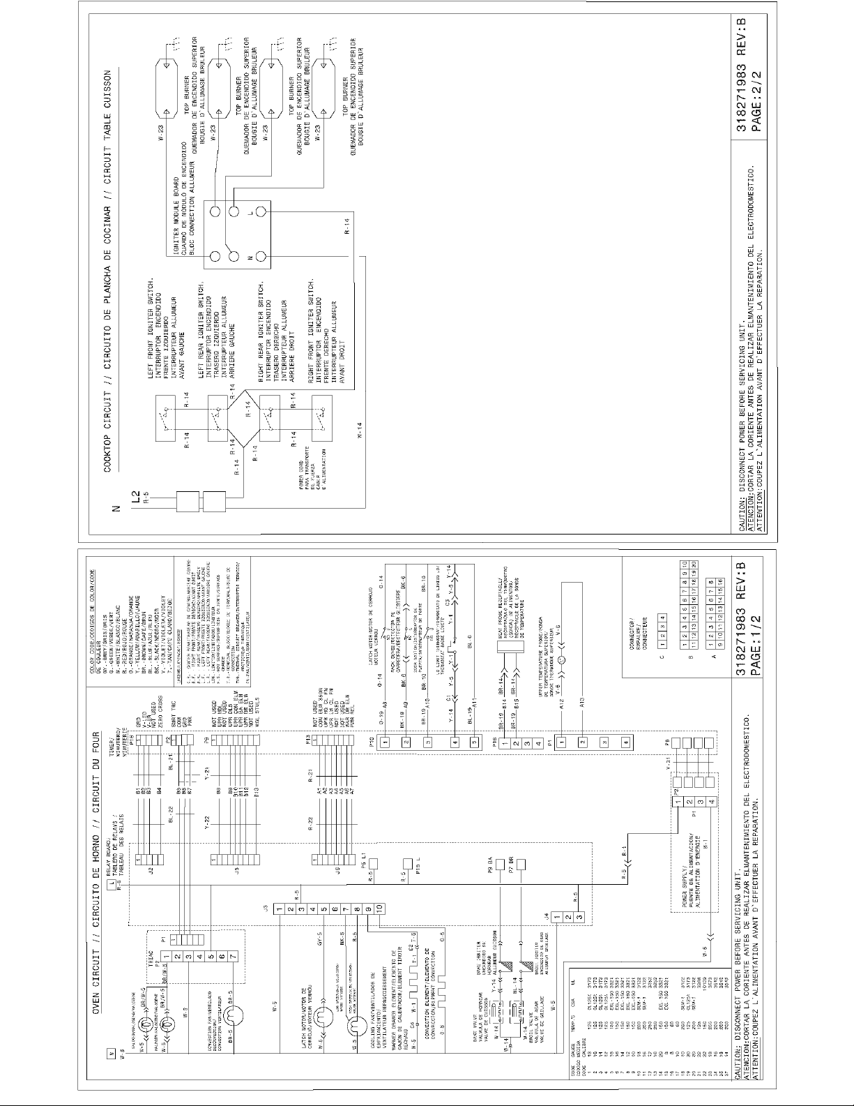
Z
o
_6
2_
D
zz
co
co
oDO.I
ob -_.
o,I LU
cOrD
03 __
oo
%
o
o
o_
w
o_
i-i-
z_
LU_
_<_
H_
N &
H_:
>_
co<
ozo
r_LU<
I--I--
_zz
_H
___O.<
_ _ N
z_w
_zm