For Outdoor Use
Owner’s Manual
www.solegourmet.com
Installation, Operation,
Maintenance & Parts Guide
Models: SO261BQTR, SO301BQRRL, SO321BQRTRL,
SO381BQRTRL, SO421BQRL
These grills are tested and certified to the ANSI-Z21.58/CSA 1.6.standards
This manual was updated in January 2014
For the latest product information visit the website

0

1
Contents
For Your Safety ................................................................................................................................ 2
Important Safety Rules ................................................................................................................... 3
Gas Connections ............................................................................................................................. 3
Installation Location & Clearances ................................................................................................. 4
Build-in Specifications ..................................................................................................................... 5
Electrical Connections ..................................................................................................................... 7
Gas Barbeque Specifications ........................................................................................................... 7
Fuel Conversion............................................................................................................................... 8
LP Tank Requirements .................................................................................................................. 10
Leak Testing & Burner Adjustments ............................................................................................. 11
Lighting Instructions ...................................................................................................................... 12
Operation, Cleaning & Maintenance ............................................................................................ 13
Front Panel & Parts Removal ........................................................................................................ 14
Troubleshooting ............................................................................................................................ 15
Parts Exploded View ..................................................................................................................... 16
Parts Identification List ................................................................................................................. 16
Wiring Diagram ............................................................................................................................. 18
Do’s & Don’ts ................................................................................................................................ 19
Warranty ....................................................................................................................................... 20
Message to the Proud Owner
Congratulations on the purchase of your new Solé Gourmet gas grill. We have designed and built this high
quality grill to provide you with years of optimum performance and longevity.
This manual gives you easy to follow instructions for installing, operating and maintaining your Solé Gourmet
grill. We recommend reading this manual carefully before your first use to ensure safety, proper care and
operation.
For any assistance, contact us at: http://solegourmet.com/support/
Thank you for purchasing your new Solé Gourmet grill. We wish you years of cooking pleasure.
For Your Records
Please record the following information and refer
to them when contacting the company or an
authorized service agent. This information can be
found on the right hand side of the grill and on the
bottom of the drip tray.
Model
Serial
Date of Purchase
Purchase Location
NG (Natural Gas) LP (Liquid Propane)
2
For Your Safety
1. Do NOT store or use gasoline
or other flammable vapors
and liquids in the vicinity of
this or any other appliance.
2. An LP cylinder not connected
for use shall not be stored in
the vicinity of this or any
other appliance.
FOR YOUR SAFETY
Read the Lighting Instructions in
this manual before lighting this
appliance.
!! WARNING !!
If You Smell Gas:
1. Shut off gas to the appliance
2. Extinguish any open flames
3. Open the lid
4. If odor persists, immediately
call your gas supplier
FOR YOUR SAFETY
Check your local building codes for the
proper method of installation. In the
absence of local codes, this unit should be
installed in accordance with the National
Fuel Gas Code No. Z223.1-CAN/CGA-B149.1,
natural gas installation code or CAN/CGA-
B149.2, propane installation code.
TESTED IN ACCORDANCE WITH ANSI
STANDARD FOR OUTDOOR COOKING
GAS APPLIANCES. THIS GRILL IS FOR
OUTDOOR USE ONLY!
The burning of gas cooking fuel generates
some by-products which are on the list of
substances which are known by the State of
California to cause cancer or reproductive
harm. California law requires businesses to
warn customers of potential exposure to
such substances. Always operate this unit
according to the use and care manual,
ensuring you provide good ventilation when
cooling with gas.
CALIFORNIA PROPOSITION 65
!! WARNING !!

3
Important Safety Rules
It is important to follow these rules to avoid fire hazard, property damage or bodily injury from
improper installation or usage of the grill. For safety, READ all rules carefully and check local codes.
It is prohibited to install the grill in recreational vehicles/mobile homes, trailers, boats, etc. The grill
is for outdoor installation and use only.
Ensure proper installation by following the installation instructions. Make sure to know where the
gas supply shut-off valve is located. It should be readily and easily accessible.
Check all gas line joints & connections for gas leak with soap water solution.
Never check gas leak with an open flame.
Do not attempt to repair or replace any part of the grill unless specifically recommended in this
manual. All other services should be performed by a qualified service technician.
Do not place clothing or other flammable material on or near the appliance. Do not wear loose-
fitting clothes or long sleeves while using the grill as some fabrics may be highly flammable.
Children should be carefully supervised when they are in the vicinity of the grill. Do not allow them
to get close while in use. Items of interest to children should not be stored in or around the grill in
the cabinet or in the masonry enclosure. Portions of the grill can be extremely hot while in use and
can cause severe burns.
Protect your hand with a glove or mitt when opening and operating the grill. Open grill lid slowly to
allow heat and smoke to escape before fully opening.
Never use aluminum foil to line the crumb pan or grill racks. This can alter airflow for proper
combustion and also build up heat in the control area causing the knobs and igniters to melt.
Grease is highly flammable. Allow hot grease to cool down before attempting to handle it. Clean
grease tray often so that grease does not accumulate and stay in it.
Do not use the grill in a windy area.
Do not obstruct the flow of air into the front of the grill.
The grill should be installed facing towards the prevailing winds to help eliminate drafts from behind
which can heat up the control panel and controls.
Always keep your grill CLEAN to eliminate grease fires which are dangerous.
Important Information Regarding Gas Connections
Check gas type – use only the type of gas indicated in the rating plate.
Do NOT connect an unregulated gas source to the appliance. You MUST use the regulator(s) that are
supplied with this appliance.
Safe and satisfactory operation depends to a great extent on the proper installation of the
appliance. The installation must comply with the local codes, or in the absence of local codes, with
either the National Fuel Gas Code, ANSI Z223.1 or CAN/CGA – B149.1 or 149.2.
Installer supplied manual gas shut-off valve must be installed in an easily accessible location in the
gas supply line ahead of the pressure regulator (4”W.C.).
The outdoor cooking gas appliance and its individual shut-off valve must be disconnected from the
gas supply piping system during any pressure testing of the system at test pressures in excess of 1/2
Psi (3.5kPa). Over-pressure will cause the valves to fail!
The outdoor cooking gas appliance must be isolated from the gas supply piping system by closing its
individual manual shut-off valve during any pressure testing of the gas supply piping system at test
pressures equal to or less than 1/2 Psi (3.5kPa).
The supply line must be sized and installed to provide a sufficient supply of gas to meet the
maximum demand of the grill without undue loss of pressure. The sealant used on the threaded
joints of the gas pipe must be a type resistant to the action of LP gases.
4
Installation Location
Choose a location where the flow of air on the front of the grill is not obstructed.
Due to high temperatures, place the grill out of traffic and keep away from clothing, furniture, etc. Keep the
gas line connection as short as possible. Do not install in recreational vehicles/mobile homes, trailers, boats,
etc.
Clearances
Combustible Construction
Minimum horizontal clearance from sides and back of the unit to adjacent vertical combustible construction
extending above top of unit, 6 inches from side and 15 inches from back. Do not locate under any overhead
combustible construction.
Non-Combustible Construction
Sides of the grill can be 0” from non-combustible wall, below the cooking surface.
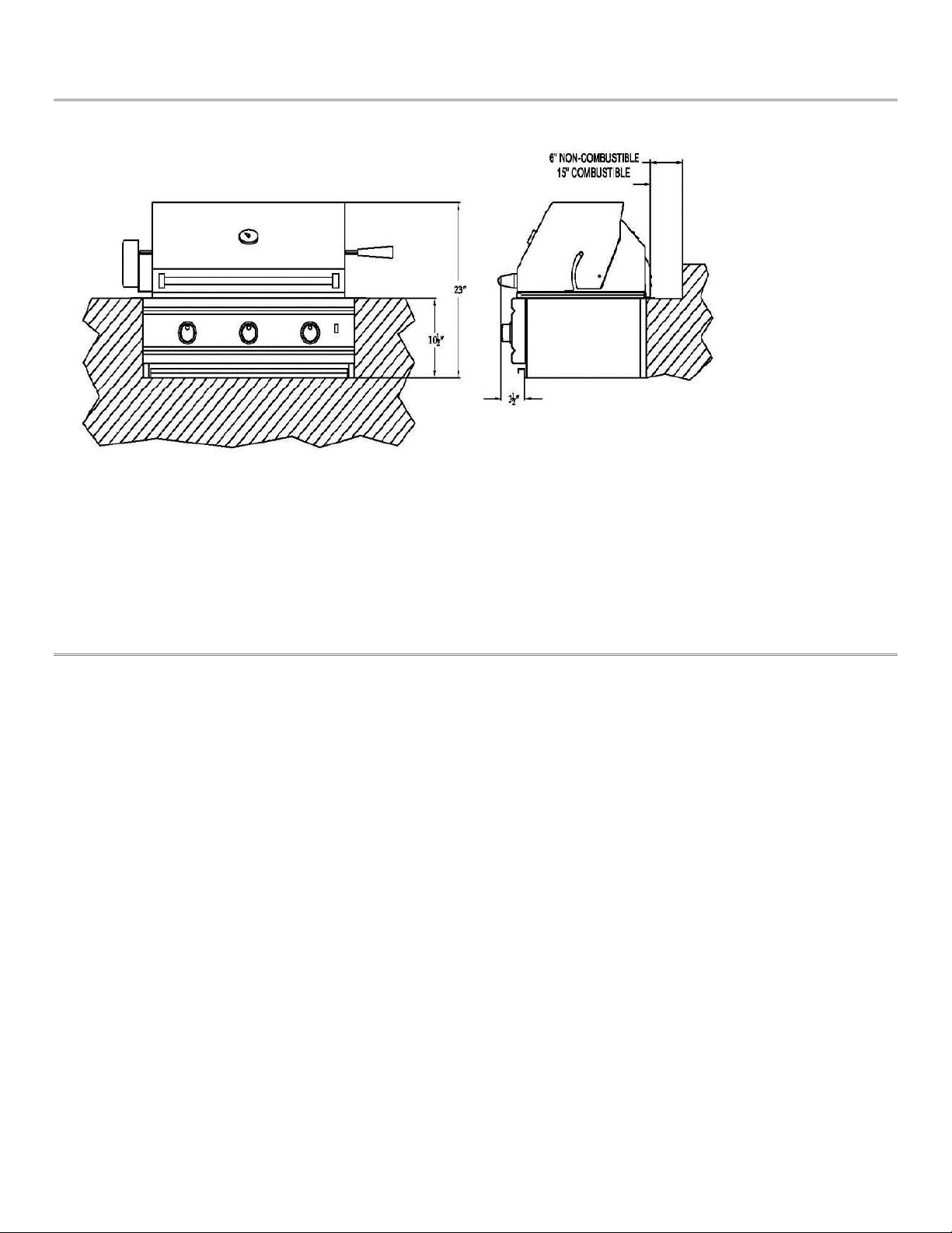
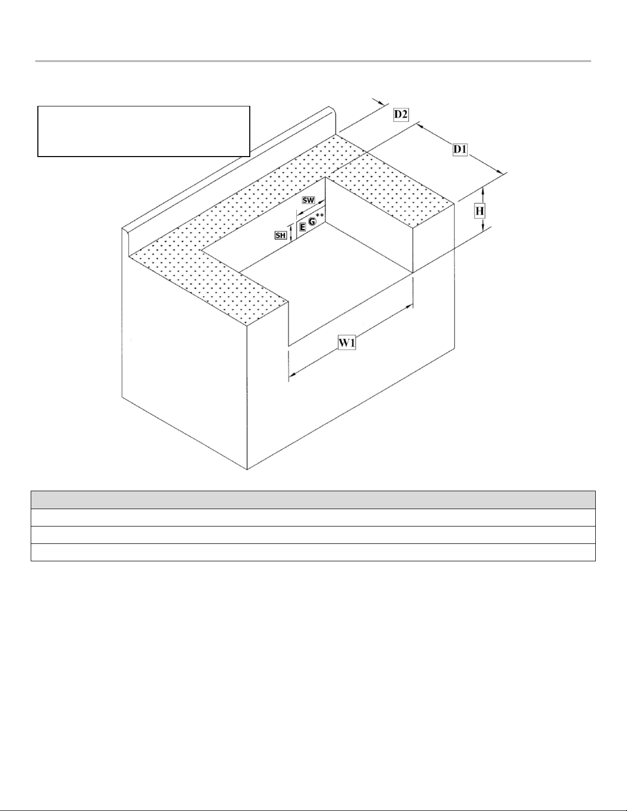
Build-in Installation
For non-combustible masonry cabinet enclosure installation only. Follow the cut-out dimensions as shown.
ALL outdoor kitchen cabinets MUST include ventilation. We recommend 12 square inches of opening for each
(running) 4 feet of counter top.
The bottom of the grill must be supported on both sides and back or full width with opening as shown for gas
connection.
5
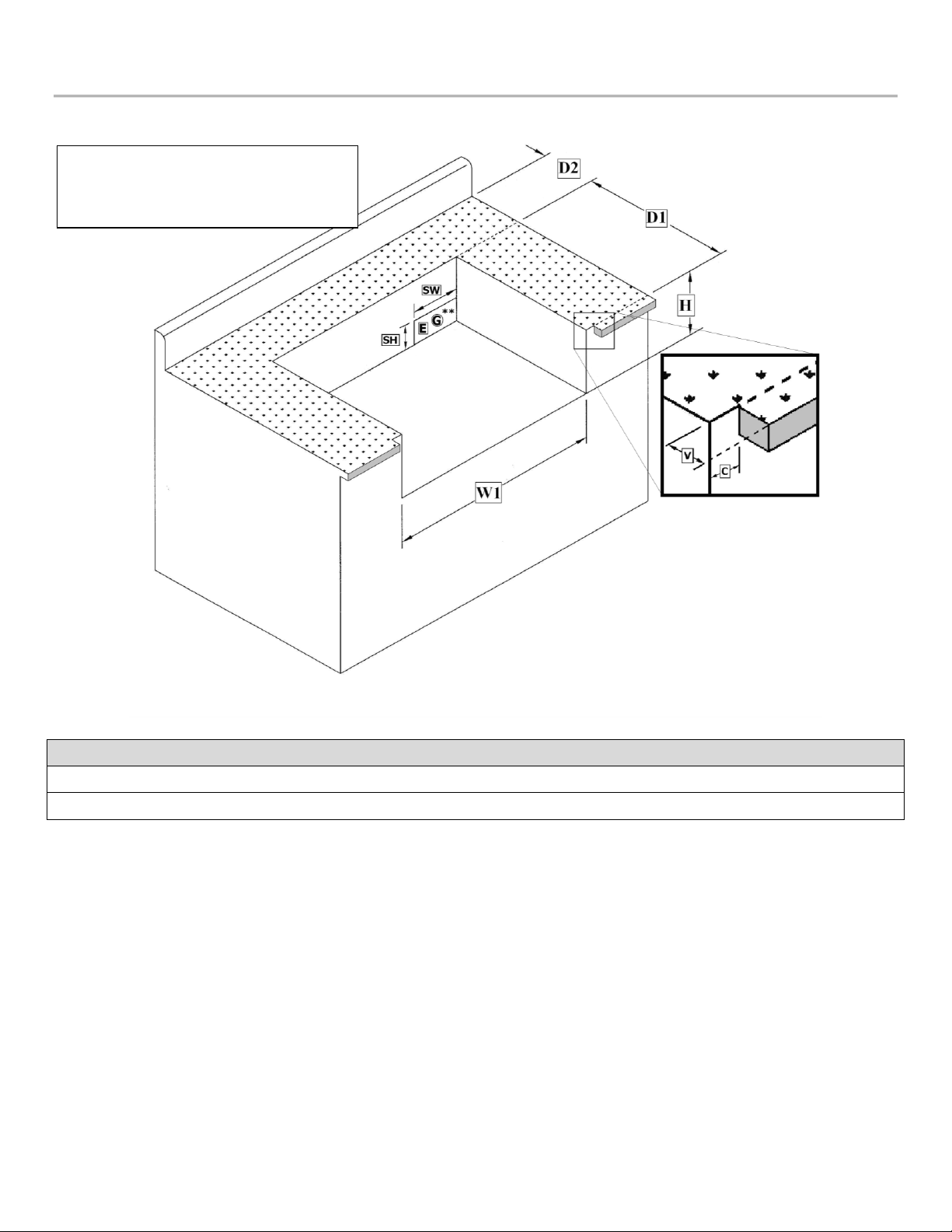
Build-in Specifications
SO301BQRRL, SO421BQRL
Model W1 D1 D2* H SW** SH** C*** V***
SO301BQRRL 33 ¼” 20” 6” 11” 6 ½” 4 ½” ¾” Varies w/Overhang
SO421BQRL 45 ¼” 20” 6” 11” 6 ½” 4 ½” ¾” Varies w/Overhang
*Non-Combustible
**E & G = Electrical & Gas Supply requiring 3 ½” depth clearances
***Applies to Left & Right Side
6” Non-Combustible Clearance
15” Combustible Clearance
from Grill
6
Build-in Specifications
SO261BQTR, SO321BQRTRL, SO381BQRTRL
Model W1 D1 D2* H SW** SH**
SO261BQTR 24 ½” 21 ½” 6” 9 ½” 6 ½” 4 ½”
SO321BQRTRL 30 ½” 21 ½” 6” 9 ½” 6 ½” 4 ½”
SO381BQRTRL 38 ½” 21 ½” 6” 9 ½” 6 ½” 4 ½”
*6” Non-Combustible
**E & G Electrical & Gas Supply Requiring 3 ½” Depth Clearances
6” Non-Combustible Clearance
15” Combustible Clearance from
Grill
7
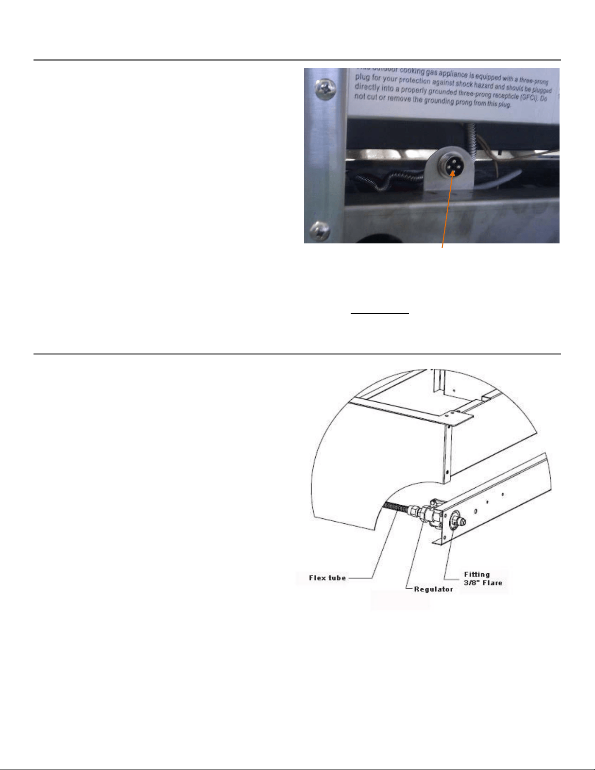
Electrical Connections
Electrical outlet for the Rotisserie motor can be
installed on the left side or right side of the grill. The
outdoor cooking gas appliance, when installed, must
be electrically grounded in accordance with local
codes or, in the absence of local codes, with the
National Electrical Code, ANSI/NFPA 70, or the
Canadian Electrical Code, CSA C22.1. Keep any
electrical supply cord and fuel supply hose away from
any heated surface.
HALOGEN LIGHT: The grill (except SO261BQTR) is
provided with a low-wattage transformer and three-
prong grounding plug for your protection against
shock hazard. Connect 115V power to the grill with a
grounded cord. USE the transformer provided!
Note: All Solé Grills come standard from the factory equipped for Natural Gas.
Gas Barbecue Specifications
BURNER INPUT RATING:
Grill 18,000 BTU / each
Rotisserie 12,500 BTU / each
Side Burner 11,500 BTU / each
Light Voltage 12VAC
Natural Gas Connection:
Appliance pressure 4” W.C.
Inlet pressure 5” – 14” W.C.
Check with your local gas utility company or with
local codes before installing gas lines.
Assemble pipe fittings as shown. Apply pipe
compound on male joints only. Install regulator
with the proper orientation for the gas flow. Be sure to use a second wrench on the flex connector
when making connections.
This plug is used for connecting the optional
SOSB2L and SOSBIRL side burners
8
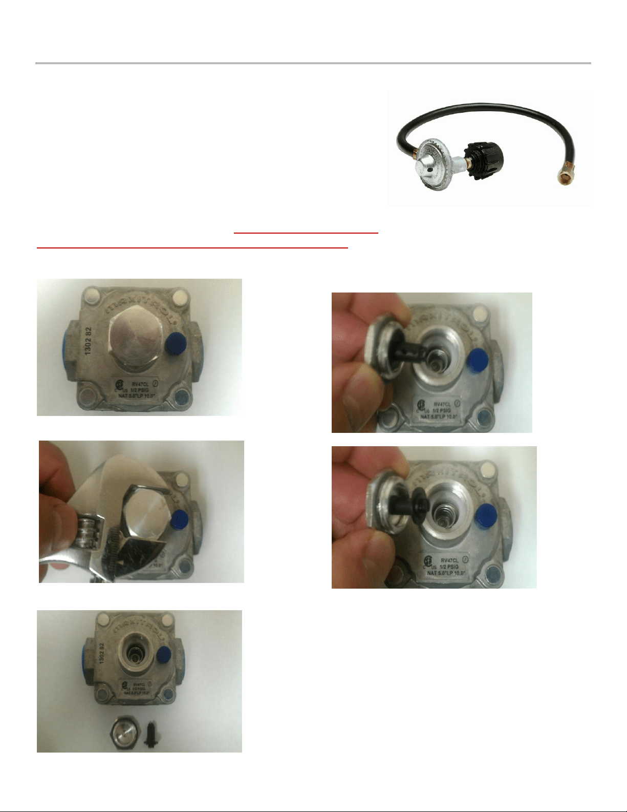
Fuel Conversion (Regulator)
*This should only be performed by a licensed gas professional*
Currently all Solé grills are supplied with an LP orifice conversion kit and
one NG/LP convertible regulator. When converting the gas orifices you
must also convert the regulator by removing the large nut on the top of
the regulator, remove the plastic plunger, flip it over to the desired fuel,
and reinstall the cap. Tighten the cap and the regulator has been
converted.
This convertible regulator will not be used if you are going to
connect a portable LP hose regulator. The LP hose regulator is not
included with the grill and needs to be purchased separately.
Regulator Conversion
Maxitrol RV47CL Convertible Regulator
1. Remove Threaded Cap
2. Cap and Plastic Plunger
Note: The plunger snaps in and out of the cap.
Regulator Converted to Natural Gas (NG)
Regulator Converted to Liquid Propane (LP)
LP Hose & Regulator (Not Included)
9
Fuel Conversion (Burners)
1. Determine the existing gas type. (LP or Natural gas) Changing the gas type and orifice change out is the
same for both gases.
2. You must remove all grates and burner covers to expose the main burners in the grill.
3. On the bottom rear of each burner is a cotter pin. Remove cotter pin.
4. Slide burner to the rear of the grill and up. Repeat for each burner.
5. Where the burner was located going through a hole in the basin and connecting to the valve is now
evacuated space.
6. Inside the space you will find the end of the valve (front of grill), with an orifice (brass fitting), screwed
into the end of the valve body.
7. Remove the orifice with a socket set and extension. These are extremely fragile when removing. Take
extra precaution when removing.
8. Replace with LP orifice supplied in the kit, (repeat for all burners). When re-installing orifice do not over
tighten or you will strip and or break the brass orifice. Minimal torque is required when tightening!
9. Replace burners and test for proper flame color and height. The flame should be blue in color with small
yellow tips. The flame height should be at ½” to 1” on low and 1.5” to 2” on high. The low flame setting
may need to be adjusted after converting the grill to LP. Please refer to step 11 listed below to adjust the
low flame setting.
10. Replace burner covers and grates.
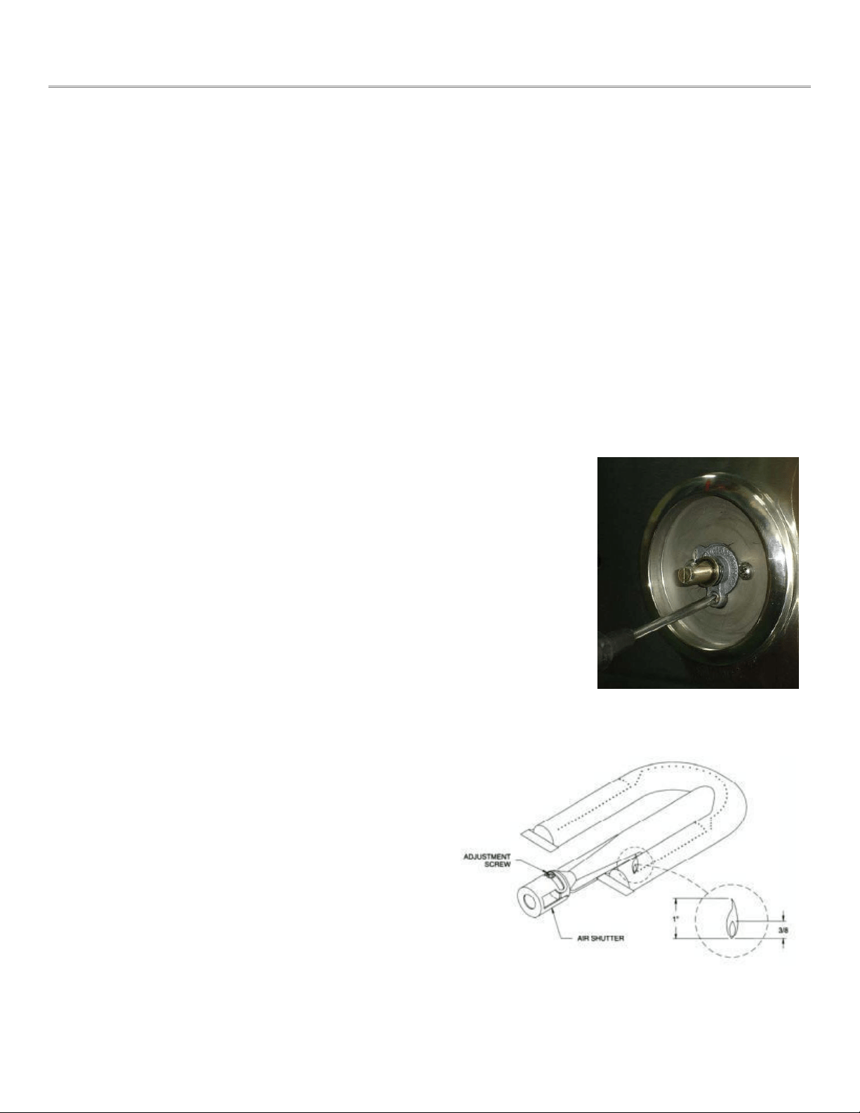
Low Flame Set Screw
11. If necessary, adjust the low flame set screw located behind the burner
control knob on the front of the valve. Back the screw out until it is flush
with the valve body.
Note: It may be necessary to adjust the air mixture on each burner after a
conversion. Typically LP gas requires more primary air so open the air mixers
to at least half open. The opposite is true for natural gas. In some cases close
these air mixer adjusters completely.
Rotisserie Burner Conversion
12. Remove the back panel at the rear of the grill, this
will expose the V shaped or pyramid shaped brass
orifice.
13. Remove the existing orifice and replace with change
out orifice.
14. Replace rear panel
10
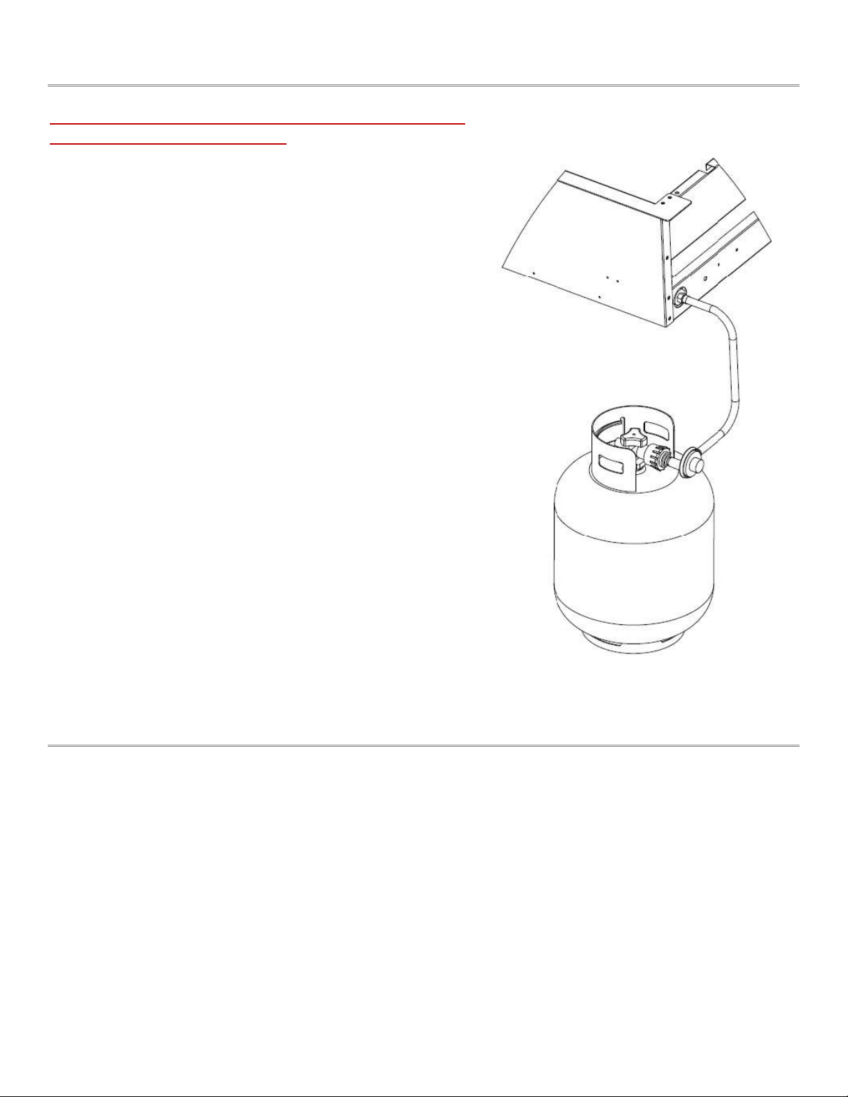
LP Gas Connection
The LP hose regulator is not included with the grill and
needs to be purchased separately.
Appliance pressure 10” W.C.
Inlet pressure 11” – 14” W.C.
Purchase a standard 20 LB. LP tank with QCC – 1 fitting.
Assemble pipe/hose assembly as shown.
After completion of assembly, turn the tank valve on and turn the
control valves on the grill to the ‘HI/IGN’ position for 10 – 15
seconds to purge the line of air.
Inspect the hose before each use of the appliance. If it is evident
there is excessive abrasion or wear, or the hose is cut, it must be
replaced prior to the appliance being put into operation. The
replacement hose assembly shall be that specified by the
manufacturer.
To connect, insert the regulator inlet into the tank valve and turn
the black coupler clockwise until the coupler tightens up. DO NOT
OVER TIGHTEN THE COUPLER.
To disconnect, turn the tank valve off. Hold the coupler sleeve and
turn counter clockwise. The inlet line will be disengaged.
If the appliance is not in use, the gas must be turned off at the
supply cylinder. Cylinder must be stored outdoors out of reach of
children and must not be stored in a building, garage or any other
enclosed area.
A dented, rusty or damaged propane cylinder must be replaced
immediately.
Check for leaks with a soapy water solution every time the
cylinder is replaced or reconnected. All leaks must be corrected
immediately. Never use an open flame to check for leaks.
LP Tank Requirements
The L.P. gas cylinder must be constructed and marked in accordance with the specifications for L.P. gas
cylinders of the U.S. Department of Transportation (DOT) and designed for use with a QCC-1 quick
disconnect system only.
The cylinder must be provided with a shut-off valve terminating in an L.P. gas supply cylinder valve outlet
specified, as applicable, for connection No. QCC-1.
The cylinder must be provided with a listed overfilling prevention device. The pressure regulator and hose
assembly supplied with the outdoor cooking gas appliance must be used. Replacement of pressure
regulators and hose assemblies can be purchased from authorized dealers.
The cylinder supply system must be arranged for vapor withdrawal. Make sure the LP cylinder has a collar to
protect the cylinder valve. Do not store a spare LP gas cylinder under on near this appliance.
(a) Never fill the cylinder beyond 80 percent full.
(b) If the information in (a) and (b) are not strictly followed, a death-causing fire or serious injury may
occur
11
Leak Testing
All gas piping and connections must be tested for leaks after
installation or service. All leaks must be corrected immediately.
Remember-before exchanging an empty bottle for a new one make
sure all control valves are in the “off” position.
Open the valve (shut-off or ‘ON’ LP tank). Test for leaks by applying
liquid soap solution to all joints. Bubbles forming indicate gas leak.
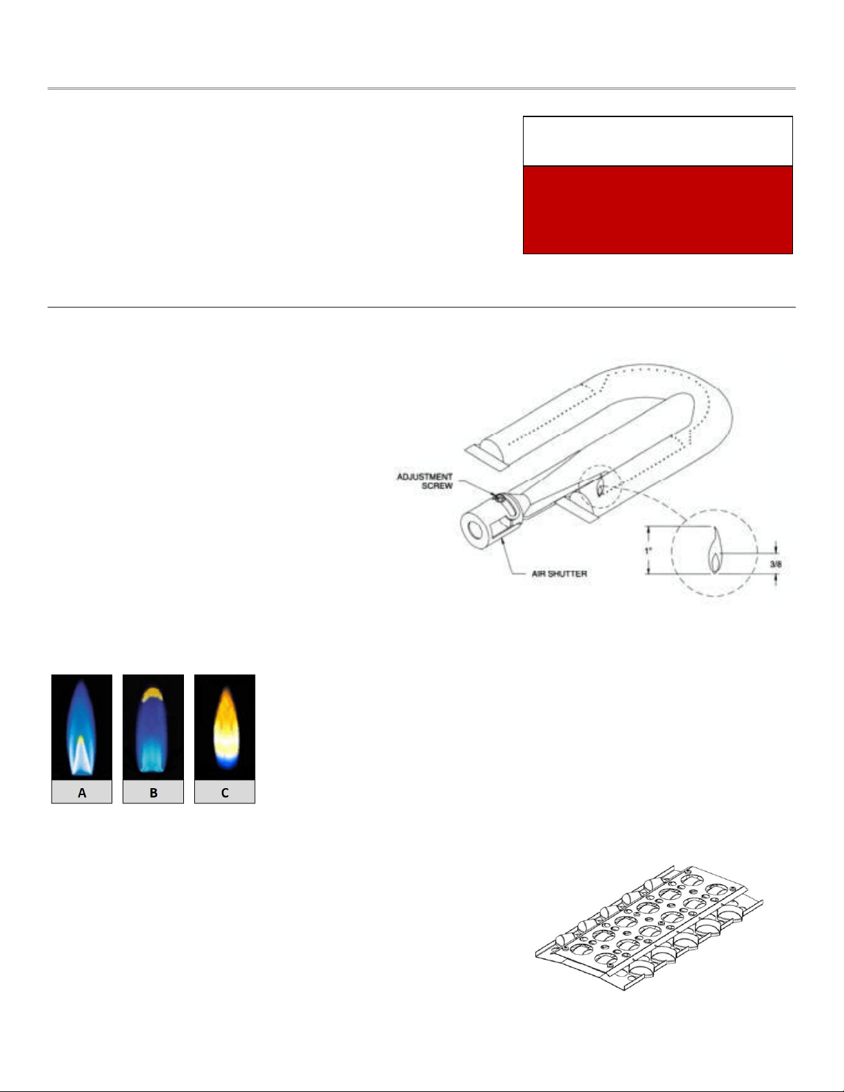
Burner Adjustments
All burners are thoroughly checked for proper lighting
and optimal flame pattern before shipment;
however, installation conditions or conversion
may necessitate minor adjustment to the air
shutter/intake. If the flame is not comparable to
figures A or B (shown below) adjust the air
shutter.
Adjusting the Air Shutter/Intake
The flame should be the full length of the burner,
blue and stable. The air intake should ONLY be
adjusted by a licensed gas professional if the
flame is lifting or has excessive amounts of
yellow visible in the flame. To gain access to the air
shutter the burner must be removed.
If flame is lifting, loosen the adjustment screw and rotate the air
shutter clockwise to achieve optimal flame pattern. Be sure to
tighten the adjustment screw before replacing the burner.
If the flame is more yellow than blue, loosen the adjustment
screw and rotate the air shutter counter clockwise to achieve
optimal flame pattern. Be sure to tighten the adjustment screw
before replacing the burner.
While replacing the burner,
ensure that the orifice is properly
seated inside the venturi opening
and that the burner is properly
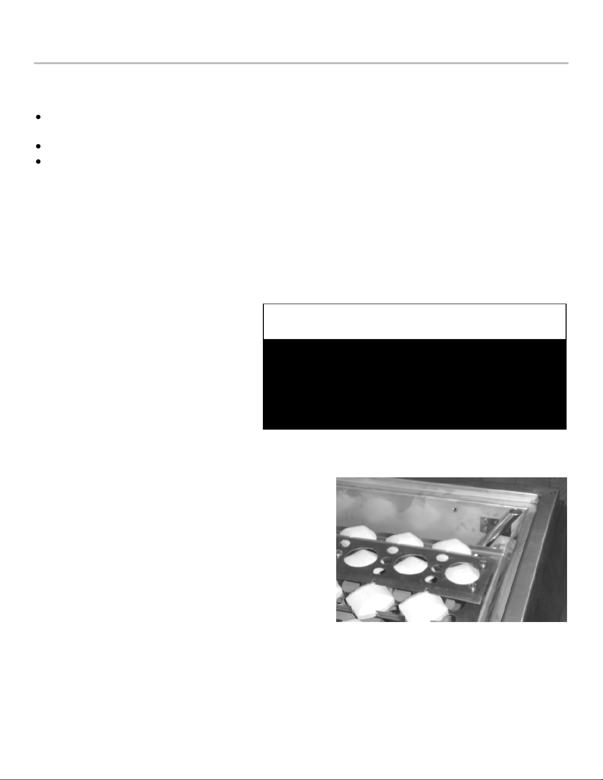
seated and secured.
Briquettes: Place briquette burner covers above each burner
NEVER USE AN OPEN FLAME
TO CHECK FOR LEAKS!
!! WARNING !!
A. Natural Gas Flame
B. Liquid Propane Flame
C. Adjust Air Shutter
12
Lighting Instructions
Before Lighting
Visually inspect the gas line, hose and all connections for signs of wear, abrasion or cuts. If evidence of
deterioration is visible, replace the part prior to use.
If you smell gas, check for leaks. If odor continues, turn off fuel supply and immediately call for service.
Keep your face and body away from the grill top when lighting.
Main/Grill Burner Lighting
1. Open lid and make sure all burners are in the ‘OFF’ position.
2. Push in and turn burner control knob to ‘HI/IGN’ position.
3. The pilot flame will ignite at this point, lighting the main burner.
4. Continue to hold the knob in until you have ignition.
5. If there is no ignition after 2-3 seconds, turn the knob back to the “OFF” position and repeat steps 2-4.
Rotisserie Burner Lighting
1. Open lid and make sure all burners are
in the ‘OFF’ position.
2. Push in and turn the rear rotisserie
control knob to “ON” position. You
should hear the igniter click and light
the rear burner.
3. If you do not see the rear burner ignite,
repeat Step 2 turning the control knob
slower before the click.
Manual Lighting
If grill or rotisserie burners do not light with igniter, they
can be lit manually. On rear burner use long butane lighter
or hearth match, turn rear burner to high and hold long
match or butane hearth lighter to burner surface. Back
burner should light immediately.
For main burners, turn knob on far right burner to high.
Place match or lighter at the top of the flash tube on right
side of basin.
Models SO301BQRRL and SO421BQRRL do not have the flash tube and must be lit directly at the U-burner.
Remove Warming Rack BEFORE turning on rear
rotisserie burner, Not doing so will result in
damage not covered under warranty!
!! VERY IMPORTANT !!

13
Operation
!! WARNING !! - DO NOT LEAVE YOUR GRILL UNATTENDED WHILE IN OPERATION!
Grill: Grill burners are controlled individually with control knobs. After lighting, turn the knob to HI, LO or in
between as desired. Turn on as many burners as required. The top cover may be closed during grilling. Keep
the top cover in closed position during the pre-heat period.
If you have included an optional infra-red burner in your grill, you must leave the lid open while the infra-red
burner is in use, due to the intense heat it can generate.
Rotisserie: Turn the control knobs to HI.
Plug in the motor power cord to a properly grounded receptacle.
Rotisserie cooking can be done with grill burners as well as with the Rotisserie burner ‘ON’.
!! IMPORTANT !! – The Motor should be stored indoors when not in use!
The skewer slides in from the side with the tip sliding into the motor shaft adapter. The slot on the handle side
should be on the side support panel edge.
Use the prongs to hold the meat. Tighten thumbscrew on the prong hubs to secure in place.
Turn the switch on the motor box to the ‘ON’ position. The skewer will rotate slowly. Stop the motor before
removing the skewer.
Cleaning & Maintenance
Cleaning; Your Barbecue grill works better and lasts longer if properly cleaned and maintained. Clean the grill
after each use. Turn grill off before starting to clean. Protect your hand with a good mitt when cleaning the
hot grill. Use a wire brush, dip in water and scrub the grill to soften and loosen food spills. The food spills will
fall into the crumb pan
!! IMPORTANT !! - Do not use Aerosol cleaners on hot grill surface. Chemicals may produce noxious fumes
and may ignite on contact with the hot surface!
Shield: Burner shields are made up of stainless steel. Occasionally, after allowing the shields to cool down,
remove and soak them in water with a mild soap or detergent. Replace when dry.
Crumb Tray / Grease Pan: Empty grease pan as required to prevent overflowing. After use, remove the full
width crumb pan and brush off the contents. Clean with hot water and soap or detergent.
!! IMPORTANT !! - NEVER line the pan with any type of foil!
All stainless steel parts should be cleaned with a mild soap or detergent or with a liquid cleanser especially
made for stainless steel. Never attempt to clean stainless steel with steel wool, abrasive cloths or powders.
14
Cleaning & Maintenance
Keep outdoor cooking gas appliance area clear and free from combustible materials, gasoline and other
flammable vapors and liquids.
Do not obstruct the flow of combustion and air ventilation. Keep the ventilation opening(s) of the cylinder
enclosure free and clear from debris.
Visually check burner flames for proper operation.
There are many different stainless steel cleaners available. Always use the mildest cleaning procedure first,
scrubbing in the direction of the grain. To touch up noticeable scratches in the stainless steel, sand very lightly
with dry 100 grit emery paper in the direction of the grain.
Specks of grease can gather on the surfaces of the stainless steel and bake on to the surface and give the
appearance of surface rust. Surface rust is caused by using steel wool or steel bristle brushes to clean the
surfaces. Never use steel wool or steel bristle brushes on the stainless steel surfaces. It can also be caused by
harsh chemicals used in the area of the grill, like common pool chemicals. NEVER store chemicals of ANY kind
in or near your grill! Surface rust may also be caused by other forms of contaminants found in the air or as a
result of foreign matter introduced to the grill.
For removal of most types of surface rust, use a slightly abrasive pad (Scotch Brite is good) in conjunction with
a stainless steel cleaner. Always rub in the direction of the grain. Surface rust is not covered under the
warranty.
The burners, control area, crumb pan, etc. should be kept clean at all times. During prolonged non-use of the
grill, spiders & insects can nest in areas that will adversely affect the functioning of the grill. Check burner
inlets, orifice hood (gas inlet to burner), igniter, sparkers, etc. thoroughly and clean before use.
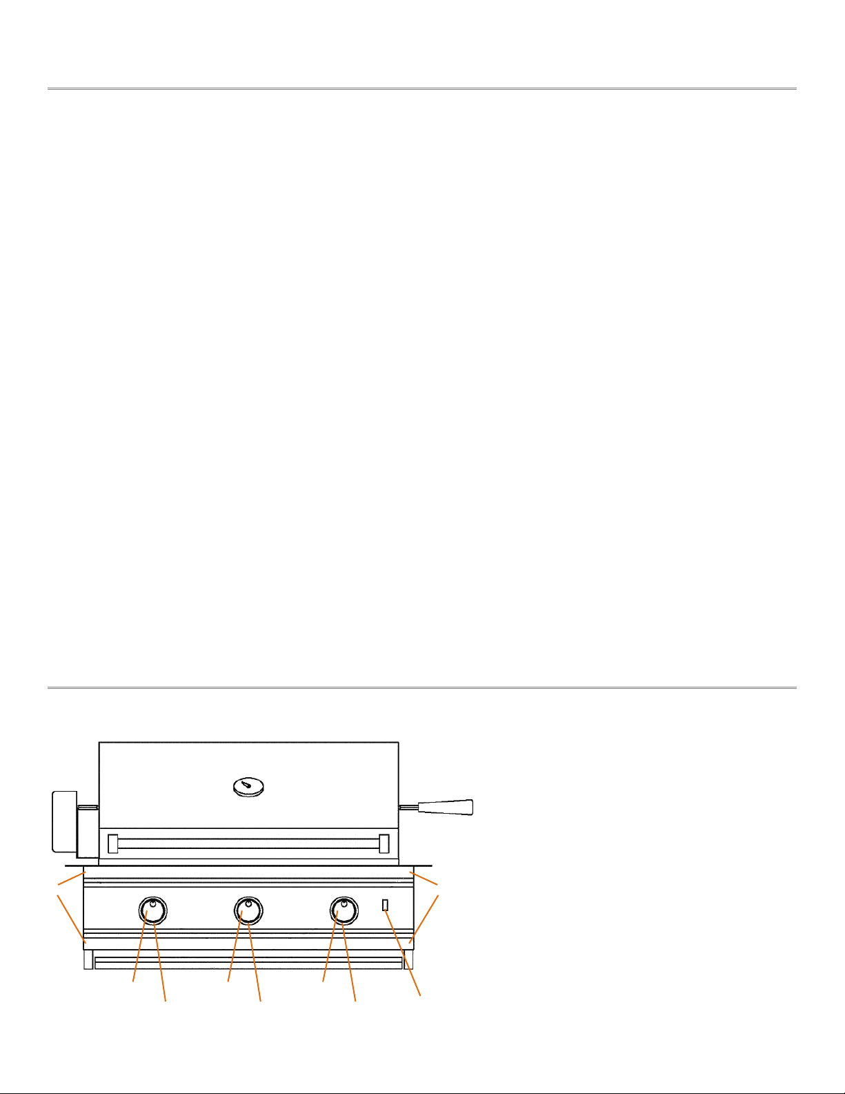
Front Panel Removal & Replacement
1. Remove all control knobs
2. Remove 2 Screws from each control
knob bezel
3. Remove 4 panel screws
4. Pull panel out slightly
5. Disconnect wires from switch
6. Replace in reverse order
1
1
1
2
2
2
3
3
5

15
Parts Removal & Replacement
Grill Burner:
- Remove top grates.
- Remove shields.
- Remove cotter pin on the bottom rear of each burner and slide out.
- Clean and replace in reverse order.
Main Burner Electrode:
Remove front panel.
- Unscrew the electrode bracket from the valve.
- Disconnect wire from the valve.
- Replace in the reverse order.
Rotisserie Electrode:
- Remove electrode cover – lift and pull.
- Remove electrode screws and pull out.
- Disconnect wire at rear.
- Replace in reverse order.
Switch:
- Remove front panel.
- Disconnect wire from switch at rear.
- Remove retaining nut and push switch from rear of the panel.
- Replace in reverse order.
Troubleshooting
Problem Solutions
Burner will not light - Check gas supply to burner by manually lighting the burners.
- Check pilot side of valve for spark while gas is off.
- Make sure spark area is clean from debris, spider webs etc.
- Make sure you now have spark.
- If no spark, check valve for defects, and replace if needed.
Improper burner flame - Check burner gas inlet area for blockage
- Check orifice hoods for any clogging and clean.
- Adjust air shutter, if necessary.
- Check pressure if flame is too low or too high.
- Check gas supply tank (LP) if running low.
Light is not ON - Connect 115V power at rear. Turn switch ON.
- Make sure the transformer was used in installation and your grill was NOT
hooked up directly to 115 volt power source.
- Check bulb and replace if necessary.
16
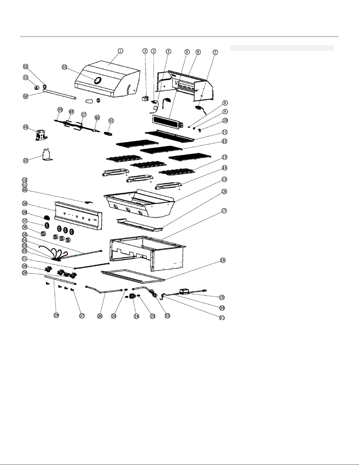
Parts Diagram
SO301BQRRL, SO421BQRL
# Part Description 301 421
01 SO-001 30" - Top Hood 1
01 SO-002 42" - Top Hood 1
02 SO-003 Igniter Bracket - IR Burner 1 1
03 SO-004 Igniter - IR Burner 1 1
04 SO-005 30" - Igniter Wire (15cm) 1
04 SO-006 42" - Igniter Wire (17cm) 1
05 SO-007 IR Burner 1 1
06 SO-008 30" - Rear Hood 1
06 SO-009 42" - Rear Hood 1
07 SO-010 Light 2 2
08 SO-011L Orifice (LPϕ1.05) IR Burner 1 1
08 SO-011N Orifice (NGϕ1.6) IR Burner 1 1
09 SO-012 Orifice Elbow Nut 1 1
10 SO-013 Orifice Elbow 1 1
11 SO-014 30" - Warming Rack 1
11 SO-015 42" - Warming Rack 1
12 SO-016 30" - Top Grate 3
12 SO-017 42" - Top Grate 4
13 SO-018 Briquette Burner Cover 3 4
14 SO-019 Tube Burner 3 4
15 SO-020 30" - Inner Basin 1
15 SO-021 42" - Inner Basin 1
16 SO-022 30" - Crumb Tray 1
16 SO-023 42" - Crumb Tray 1
17 SO-024 30" - Basin Frame 1
17 SO-025 42" - Basin Frame 1
18 SO-026 30" - Grease Tray 1
18 SO-027 42" - Grease Tray 1
19 SO-028 Transformer 1 1
20 SO-029 Transformer Inlet Cord 1 1
21 SO-030 Terminal Block 1 1
22 SO-031 LP Regulator 1 1
23 SO-032 NG Flare Fitting 2 2
24 SO-033 NG Regulator 1 1
25 SO-034 LP Flare Fitting 1 1
26 SO-035 Flex Tube (610mm) 1 1
27 SO-036 Valve Latch 4 5
28 SO-037 30" - Manifold 1
28 SO-038 42" - Manifold 1
29 SO-039 Gas Valve - IR Burner 1 1
30 SO-040L Gas Valve (LPϕ1.3) Tube 3 4
30 SO-040N Gas Valve (NGϕ1.93) Tube 3 4
31 SO-041 Flex Tube (1050mm) IR Burner 1 1
32 SO-042 LED Module Holder 1 1
33 SO-043 LED Module 1 1
34 SO-044 30" - LED w/Wire 1
34 SO-045 42" - LED w/Wire 1
35 SO-046 Side Burner LED Outlet 1 1
36 SO-047 Control Knob 4 5
37 SO-048 Knob Bezel 4 5
38 SO-049 Solé Logo Plate 1 1
39 SO-050 30" - Control Panel 1
39 SO-051 42" - Control Panel 1
40 SO-052 Light Switch 1 1
41 SO-053 LED Switch 1 1
42 SO-054 30" - Light Wire 1
42 SO-055 40" Light Wire 1
43 SO-056 Rotisserie Motor Bracket 1 1
44 SO-057 Rotisserie Motor 1 1
45 SO-058 Rotisserie Handle 1 1
46 SO-059 Rotisserie Spit Collar 1 1
47 SO-060 Screw - Skewer Fork 3 3
48 SO-061 Skewer Fork ϕ5 2 2
49 SO-062 30" - Skewer Rod 1
49 SO-063 42" - Skewer Rod 1
50 SO-064 30" - Hood Handle 1
50 SO-065 42" - Hood Handle 1
51 SO-066 End Cap - Handle 2 2
52 SO-067 End Cap Spacer - Handle 2 2
53 SO-068 Temperature Gauge 1 1
17
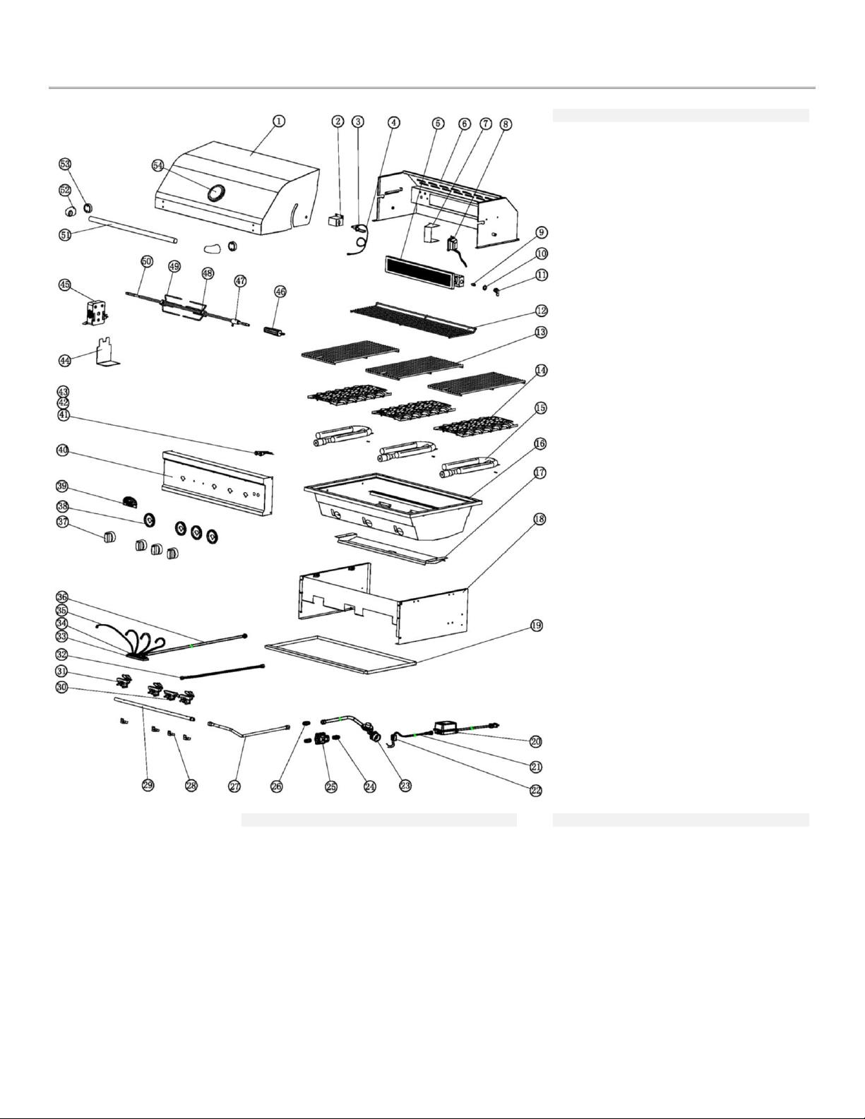
Parts Diagram
SO261BQTR, SO321BQRTRL, SO381BQRTRL
# Part Description 261 321 381
01 SOTR-001 26" - Top Hood 1
01 SOTR-002 32" - Top Hood 1
01 SO-003 38" - Top Hood 1
02 SO-004 Igniter Bracket 1 1
03 SOTR-003 Igniter - IR Burner 1 1
04 SOTR-004 32" Igniter Wire (14cm) 1
04 SOTR-005 38" Igniter Wire (16cm) 1
05 SOTR-006 IR Burner 1 1
06 SOTR-007 26" - Rear Hood 1
06 SOTR-008 32" - Rear Hood 1
06 SOTR-009 38" - Rear Hood 1
07 SOTR-010 Light Box (Right) 1 1
07 SOTR-011 Light Box (Left) 1
08 SOTR-012 Light (Right) 1 1
08 SOTR-013 Light (Left) 1
09 SO-011LP Orifice (LPϕ1.05) 1 1
09 SO-011NG Orifice (NGϕ1.6) 1 1
10 SO-012 Orifice Elbow Nut 1 1
11 SO-013 Orifice Elbow 1 1
12 SOTR-014 26" - Warming Rack 1
12 SOTR-015 32" - Warming Rack 1
12 SOTR-016 38" - Warming Rack 1
13 SOTR-017 26" - Top Grate 2
13 SOTR-018 32" - Top Grate 3
13 SOTR-019 38" - Top Grate 4
14 SO-018 Briq. Burner Cover 2 3
14 SOTR-020 Briq. Burner Cover (Sm) 4
15 SO-019 Tube Burner 2 3 4
16 SOTR-021 26" - Inner Basin 1
16 SOTR-022 32" - Inner Basin 1
16 SOTR-023 38" - Inner Basin 1
17 SOTR-024 26" - Crumb Tray 1
17 SOTR-025 32" - Crumb Tray 1
17 SOTR-026 38" - Crumb Tray 1
18 SOTR-027 26" - Basin Frame 1
18 SOTR-028 32" - Basin Frame 1
18 SOTR-029 38" - Basin Frame 1
19 SOTR-030 26" - Grease Tray 1
19 SOTR-031 32" - Grease Tray 1
19 SOTR-032 38" - Grease Tray 1
20 SO-028 Transformer 1 1 1
21 SO-029 Transformer Inlet Cord 1 1 1
22 SO-030 Terminal Block 1 1 1
23 SO-031 LP Regulator 1 1 1
24 SO-032 NG Flare Fitting 2 2 2
25 SO-033 NG Regulator 1 1 1
26 SO-034 LP Flare Fitting 1 1 1
27 SO-035 Flex Tube (610mm) 1 1 1
28 SO-036 Valve Latch 3 4 5
29 SOTR-033 26" - Manifold 1
29 SOTR-034 32" - Manifold 1
29 SOTR-035 38" - Manifold 1
30 SO-039 Gas Valve - IR Burner 1 1
31 SOTR-036L Gas Valve (LPϕ1.3) 2 3 4
31 SOTR-036N Gas Valve (NGϕ1.93) 2 3 4
32 SOTR-037 Flex Tube (980mm) 1
32 SO-041 Flex Tube (1050mm) 1
33 SO-042 LED Module Holder 1 1
34 SO-043 LED Module 1 1
35 SOTR-038 32" - LED w/Wire 1
# Part Description 261 321 381 # Part Description 261 321 381
35 SOTR-039 38" - LED w/Wire 1 51 SOTR-047 26" - Hood Handle 1
36 SO-046 Side Burner LED Outlet 1 1 51 SOTR-048 32" - Hood Handle 1
37 SO-047 Control Knob 2 4 5 51 SOTR-049 38" - Hood Handle 1
38 SO-048 Knob Bezel 2 4 5 52 SO-066 Handle End Cap 2 2 2
39 SO-049 Solé Logo Plate 1 1 1 53 SO-067 Handle End Cap Spacer 2 2 2
40 SOTR-040 26" - Control Panel 1 54 SO-068 Temperature Gauge 1 1 1 40
SOTR-041 32" - Control Panel 1
40 SOTR-042 38" - Control Panel 1
41 SO-052 Light Switch 1 1
42 SO-053 LED Switch 1 1
43 SOTR-043 32" - Light Wire 1
43 SOTR-044 38" - Light Wire 1
44 SO-056 Rotisserie Motor Bracket 1 1
45 SO-057 Rotisserie Motor 1 1
46 SO-058 Rotisserie Handle 1 1
47 SO-059 Rotisserie Spit Collar 1 1
48 SO-060 Screw - Skewer Fork 3 3
49 SO-061 Skewer Fork ϕ5 2 2
50 SOTR-045 32" - Skewer Rod 1
50 SOTR-046 38" - Skewer Rod 1
18
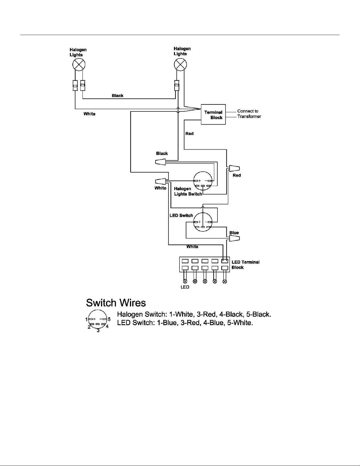
Wiring Diagram

19
Do's & Don'ts
DO…
Have propane cylinder (LP units) filled by authorized LP supplier.
Record your grill model number on your instructions and keep the instructions and parts
list in a convenient place.
Check all gas line connections for leaks with soapy solution prior to lighting, tighten until
bubbles disappear.
Raise the hood before lighting the burner.
Preheat the grill 5 minutes maximum before cooking.
After cooking, turn the grill off, then take a long handled soft brass bristle brush and
brush off the cooking grills. Then turn off gas at the Propane tank or main valve.
Use a mitt to turn off tank valve, it can get hot.
Cook with hood down when possible. It is generally faster and more efficient. Trapped
smoke adds to the flavor.
Turn the gas off promptly should you be unable to light the grill immediately. Wait a full 5
minutes before attempting to light grill again.
Have proper tools, tongs, mittens and hot pads ready prior to removing foods.
Trim excess fats from meats to minimize flare-ups.
Let the grill cool before removing any parts for cleaning.
Be careful of the control valve setting. LP gas is hotter and the lower setting may be
generally preferred.
Cover the barbecue when not in use.
Use a mitt or glove when opening BBQ lid or turning off Propane tank valve after use
DON'T…
Install grill closer than 14" on the sides or 16" on the back to any combustible
construction.
Attempt any adjustment of the regulator, it has been preset and tested.
Allow the LP tank to lie on its side. Keep in an upright position.
Use plastics or un-tempered glass utensils on the grill.
Attempt to move an aluminum foil pan while it is hot. Let it cool first before moving it.
Cover or block any air openings in the bottom of the grill with foil.
Wear long, loose flowing clothing around the grill. Long flowing hair is also easily ignited
especially by unexpected flare-ups. Tie hair back or wear a hat or a scarf.
Put food on the grill and leave it unattended or unwatched for long periods. Most fats can
catch fire even on the lower setting.
Clean Flame Tamers in any solution other than boiling detergent water. Then rinse well,
dry and reuse.
Use caustic materials (i.e. lye) to clean grill parts.
Store any additional Propane gas tanks under barbecue. When cooking with hood closed
NEVER exceed temperatures of 480°F (250°C).

20
Solé Gourmet Luxury & TR Series Limited Warranty
LIMITED WARRANTY
Solé, warrants to the ORIGINAL PURCHASER of each Outdoor Gas Grill that when subject to normal residential use, it is free from defects in
material and workmanship for set periods below. It does not apply to rust, corrosion, oxidation or discoloration, which may occur due to moisture
or overheating. This warranty does not cover parts becoming defective through misuse, accidental damage, electrical damage, improper handling,
storage, and/or installation, unauthorized adjustments or calibrations or not installed in accordance with local codes. Product must be installed
(and gas must be connected) as specified in the instructions or operator's manual, by a qualified professional installer. It does not cover labor or
labor related charges. There will be shipping and handling charge for the delivery of the warranty part(s). The warranty is only valid at the original
site of delivery with a valid proof of purchase of item(s).
Solé may require the return of defective parts for examination before issuing replacement parts. If you are required to return defective parts,
shipping charges must be prepaid by the customer. Upon examination and to Solé’s determination, if the original part is proven defective, Solé may
approve your claim and elect to replace such parts without charge. No part returns will be accepted without prior authorization from. In any
instance, customer is responsible for shipping and handling of the replacement parts. Product repair as provided under this warranty is your
exclusive remedy.
Fifteen (15) year Limited Warranty on stainless steel body housings and burners
Five (5) year Limited Warranty on stainless steel briquette trays (excludes ceramic briquettes), cooking grates, basin and drip tray for material
defects.
Two (2) year Limited Warranty the gas valves and ignition system to be free from defects in materials and workmanship
One (1) year Limited Warranty on all of its component parts including ignition system, gas system, lights, rotisserie motor, infrared burners,
etc, to be free from defects in materials and workmanship
Ninety (90) Day Limited Warranty on units installed in non-residential application such as day care centers, bed and breakfast centers,
churches, nursing homes, schools, private clubs, home owner associations, any application beyond single family. The actual part will be
repaired or replaced, free of charge, with the owner paying for all other costs including labor and freight. This warranty excludes all
commercial locations such as restaurants and food service locations.
WARRANTY LIMITATIONS & EXCLUSIONS
The warranty coverage begins on the original date of purchase and proof of date of purchase is required. In order to activate the warranty, we
require that you send in the attached warranty registration card. This warranty applies only to the original owner and may not be transferred.
This warranty specifically excludes liability for indirect, incidental, or consequential damages. In the event of any warranty replacement, all
removal, replacement, installation and shipping costs are the responsibility of the grill owner. This warranty shall apply only to the products
purchased and located in the continental United States. Some states do not allow the exclusion or limitation of incidental or consequential
damages, so the above exclusion may not apply to you. This warranty gives you specified legal rights, and you may have other rights that may vary
from state to state. Solé shall not be liable for incidental, consequential, special or contingent damages resulting from its breach of this written
warranty or any implied warranty.
What is not covered: Solé shall not be responsible for and shall not pay for the following:
Installation or start-up, damages or problems caused by improper installation or use;
Service by an unauthorized service provider;
Damage or repair due to service by an unauthorized service provider or use of unauthorized parts;
To correct normal adjustments or settings, due to improper installation, commissioning or local gas supply properties;
Shipping and handling costs, export duties, installation, removal, or re-installation cost;
Normal adjustment to burners, gas regulators, etc
Cleaning of igniters and/or general maintenance.
The cost of a service call to diagnose trouble.
Implied warranty shall not extend beyond the duration of this written warranty. This warranty supersedes any and all other warranties expressed
or implied and all other obligations, or liabilities related to the sale or use of Solé Grill products.
WARRANTY SERVICE & REPLACEMENT PARTS
For technical troubleshooting, to obtain replacement components or parts and/or service inquiries, please call Solé at (800) 793-7334, 8am-4:30pm
PST, Monday-Friday.
Before you call for service:
Is there Gas Supplied to the Grill?
Is there a power outage in the area (lights will not work)?
Have you recently refilled the LP Tank?
When calling for Warranty service, please make sure you have the
following information:
Purchasers name
Model Number
Date of Purchase
Proof of Purchase by Original Owner
Serial Number. (Note: The serial number can be found on the
right hand side of the grill and on the bottom of the drip tray.)
Have an accurate description of the problem
For email assistance:
All other forms of correspondence:
Solé Gourmet
4320 Roseville Road.
North Highlands, CA 95660
ATTN: Warranty Service Department
If shipment arrives damaged:
Visible Loss or Damage – Be certain this is noted on freight bill
or express receipt and signed by person making delivery.
File Claim for Damages Immediately – Regardless of extent of
damage.
Concealed Loss or Damage – If damage is unnoticed until
merchandise is unpacked, notify transportation company or
carrier immediately and file a “concealed damage” claim with
them. This should be done within (15) days of date delivery is
made to you. Be sure to retain container for inspection. We
cannot assume responsibility for damage or loss incurred in
transit.

8
9
www.solegourmet.com