
0099001556-00
SPC3
3A Wireless Charger/Maintainer
3A Cargador / Mantenedor Inalámbrico
OWNERS MANUAL
MANUAL DEL USUARIO
Connect via
the Schulink
G1 Gateway.
Conectar a través
de la Schulink
G1 Gateway.


CONTENTS
IMPORTANT SAFETY INSTRUCTIONS ......................................................................................5
PERSONAL SAFETY PRECAUTIONS ........................................................................................5
PREPARING TO CHARGE ..........................................................................................................6
CHARGER LOCATION ................................................................................................................6
DC CONNECTION PRECAUTIONS ............................................................................................6
FOLLOW THESE STEPS WHEN BATTERY IS INSTALLED IN VEHICLE ..................................6
FOLLOW THESE STEPS WHEN BATTERY IS OUTSIDE VEHICLE ..........................................7
GROUNDING AND AC POWER CORD CONNECTIONS ...........................................................7
ASSEMBLY INSTRUCTIONS ......................................................................................................7
FEATURES ...................................................................................................................................8
CONTROL PANEL ........................................................................................................................8
INSTALLING THE APP .................................................................................................................9
SETTING UP THE WIRELESS CONNECTION ......................................................................... 10
USING THE APP TO CONTROL THE CHARGER ..................................................................... 11
OPERATING THE CHARGER ...................................................................................................14
DISPLAY MESSAGES ...............................................................................................................16
MAINTENANCE AND CARE ...................................................................................................... 16
TROUBLESHOOTING ...............................................................................................................17
BEFORE RETURNING FOR REPAIRS .....................................................................................18
SPECIFICATIONS ......................................................................................................................18
REPLACEMENT PARTS / ACCESSORIES ...............................................................................18
LIMITED WARRANTY ................................................................................................................ 19
WARRANTY CARD .................................................................................................................... 35

CONTENIDOS
INSTRUCCIONES IMPORTANTES DE SEGURIDAD ...............................................................20
PRECAUCIONES DE SEGURIDAD PERSONAL ......................................................................20
PREPARACIÓN PARA LA CARGA ...........................................................................................21
UBICACIÓN DEL CARGADOR .................................................................................................. 21
PRECAUCIONES DE CONEXIÓN EN CC ................................................................................21
SIGA ESTOS PASOS CUANDO LA BATERÍA ESTÉ COLOCADA EN EL VEHÍCULO ............. 22
SIGA ESTOS PASOS CUANDO LA BATERÍA SE ENCUENTRE FUERA DEL VEHÍCULO ......22
CONEXIONES A TIERRA Y ENERGÍA DE CA...........................................................................22
INSTRUCCIONES DE MONTAJE ..............................................................................................23
CARACTERÍSTICAS ..................................................................................................................23
PANEL DE CONTROL ................................................................................................................24
INSTALACIÓN DE LA APLICACIÓN .......................................................................................... 24
CONFIGURACIÓN DE LA CONEXIÓN INALÁMBRICA ............................................................25
USO DE LA APLICACIÓN PARA CONTROLAR EL CARGADOR ............................................. 26
FUNCIONAMIENTO DEL CARGADOR .....................................................................................29
MUESTRA DE MENSAJES ........................................................................................................31
MANTENIMIENTO Y CUIDADO.................................................................................................32
LOCALIZACIÓN Y SOLUCIÓN DE PROBLEMAS .....................................................................32
ANTES DE DEVOLVER A REPARACIONES ............................................................................. 33
ESPECIFICACIONES ................................................................................................................33
REPUESTOS / ACCESORIOS ...................................................................................................33
GARANTÍA LIMITADA ................................................................................................................34
TARJETA DE GARANTÍA ...........................................................................................................35

• 5 •
1. IMPORTANT SAFETY INSTRUCTIONS
PLEASE SAVE THIS OWNERS MANUAL
AND READ BEFORE EACH USE.
This manual will explain how to use the
charger safely and effectively. Please
read and follow these instructions and
precautions carefully.
NOTE: The charger itself is a stand-alone
device and will function as a battery charger/
maintainer without an internet connection.
However, without a Cloud connection, the
App will not reect the charging progress.
1.1 SAVE THESE INSTRUCTIONS –
This manual contains important safety
and operating instructions.
1.2 Keep out of reach of children.
1.3 Do not expose the charger to rain or snow.
1.4 Use of an attachment not recommended
or sold by Schumacher
®
Electric
Corporation may result in a risk of re,
electric shock or injury to persons.
1.5 To reduce the risk of damage to electric
plug and cord, pull by the plug rather than
the cord when disconnecting charger.
1.6 An extension cord should not be used
unless absolutely necessary. Use of
improper extension cord could result
in a risk of re and electric shock. If an
extension cord must be used, make sure:
• The pins on plug of extension cord are
the same number, size and shape as
those of plug on charger.
• The extension cord is properly wired and
in good electrical condition
• The wire size is large enough for AC
ampere rating of charger, as specied in
section 8.
1.7 Do not operate charger with damaged
cord or plug – replace the cord or plug
immediately.
1.8 Do not operate charger if it has received
a sharp blow, been dropped, or otherwise
damaged in any way; take it to a qualied
serviceman.
1.9 Do not disassemble charger; take it to
a qualied serviceman when service or
repair is required. Incorrect reassembly
may result in a risk of electric shock or re.
1.10 To reduce risk of electric shock, unplug
charger from outlet before attempting
any maintenance or cleaning. Turning off
controls will not reduce this risk.
1.11 WARNING: RISK OF EXPLOSIVE GASES.
a. WORKING IN VICINITY OF A LEAD-
ACID BATTERY IS DANGEROUS.
BATTERIES GENERATE EXPLOSIVE
GASES DURING NORMAL BATTERY
OPERATION. FOR THIS REASON, IT
IS OF UTMOST IMPORTANCE THAT
YOU FOLLOW THE INSTRUCTIONS
EACH TIME YOU USE THE
CHARGER.
b. To reduce risk of battery explosion, follow
these instructions and those published by
battery manufacturer and manufacturer of
any equipment you intend to use in vicinity
of battery. Review cautionary markings on
these products and on the engine.
1.12 Pursuant to California Proposition 65, this
product contains chemicals known to the
State of California to cause cancer and
birth defects or other reproductive harm.
Wash hands after handling.
2. PERSONAL SAFETY PRECAUTIONS
2.1 Consider having someone close enough
by to come to your aid when you work
near a lead-acid battery.
2.2 Have plenty of fresh water and soap
nearby in case battery acid contacts skin,
clothing, or eyes.
2.3 Wear complete eye protection and
clothing protection. Avoid touching eyes
while working near battery.
2.4 If battery acid contacts skin or clothing,
wash immediately with soap and water. If
acid enters eye, immediately ood eye with
running cold water for at least 10 minutes
and get medical attention immediately.
2.5 NEVER smoke or allow a spark or ame
in vicinity of battery or engine.
2.6 Be extra cautious to reduce risk of
dropping a metal tool onto battery. It might
spark or short-circuit battery or other
electrical part that may cause explosion.
2.7 Remove personal metal items such as
rings, bracelets, necklaces, and watches
when working with a lead-acid battery. A
lead-acid battery can produce a short-
circuit current high enough to weld a ring
or the like to metal, causing a severe burn.
2.8 Use the charger for charging only 6 and
12V LEAD-ACID, GEL and AGM-type
rechargeable batteries with recommended
rated capacities of 12Ah (6V) and 12-
59Ah (12V). It is not intended to supply
power to a low voltage electrical system
other than in a starter-motor application.
Do not use battery charger for charging
dry-cell batteries that are commonly used
with home appliances. These batteries
may burst and cause injury to persons
and damage to property.
2.9 NEVER charge a frozen battery.

• 6 •
3. PREPARING TO CHARGE
3.1 If necessary to remove battery from
vehicle to charge, always remove
grounded terminal from battery rst. Make
sure all accessories in the vehicle are off,
so as not to cause an arc.
3.2 Be sure area around battery is well
ventilated while battery is being charged.
3.3 Clean battery terminals. Be careful to keep
corrosion from coming in contact with eyes.
3.4 Add distilled water in each cell until battery
acid reaches level specied by battery
manufacturer. Do not overll. For a battery
without removable cell caps, such as valve
regulated lead acid batteries, carefully follow
manufacturer’s recharging instructions.
3.5 Study all battery manufacturer’s
specic precautions while charging and
recommended rates of charge.
3.6 Determine voltage of battery by referring
to car owner’s manual and make sure
that output voltage selector switch is
set at correct voltage. If charger has
adjustable charge rate, charge battery
initially at lowest rate. For a charger not
having an output voltage selector switch,
determine voltage of battery by referring
to car owner’s manual and make sure it
matches output rating of battery charger.
4. CHARGER LOCATION
4.1 Locate charger as far away from battery
as DC cables permit.
4.2 Never place charger directly above
battery being charged; gases from battery
will corrode and damage charger.
4.3 Never allow battery acid to drip on
charger when reading electrolyte specic
gravity or lling battery.
4.4 Do not operate charger in a closed-in
area or restrict ventilation in any way.
4.5 Do not set a battery on top of charger.
5. DC CONNECTION PRECAUTIONS
5.1 Connect and disconnect DC output clips
only after setting any charger switches to
“off” position and removing AC cord from
electric outlet. Never allow clips to touch
each other.
5.2 Attach clips to battery and chassis, as
indicated in sections 6 and 7.
6. FOLLOW THESE STEPS WHEN BATTERY IS INSTALLED IN VEHICLE
A SPARK NEAR THE BATTERY MAY
CAUSE A BATTERY EXPLOSION.
TO REDUCE THE RISK OF A SPARK
NEAR THE BATTERY:
6.1 Position AC and DC cords to reduce risk
of damage by hood, door, or moving
engine part.
6.2 Stay clear of fan blades, belts, pulleys,
and other parts that can cause injury to
persons.
6.3 Check polarity of battery posts. POSITIVE
(POS, P, +) battery post usually has larger
diameter than NEGATIVE (NEG, N,–) post.
6.4 Determine which post of battery is
grounded (connected) to the chassis. If
negative post is grounded to chassis (as
in most vehicles), see (6.5). If positive
post is grounded to the chassis, see (6.6).
6.5 For negative-grounded vehicle, connect
POSITIVE (RED) clip from battery
charger to POSITIVE (POS, P, +)
ungrounded post of battery. Connect
NEGATIVE (BLACK) clip to vehicle
chassis or engine block away from
battery. Do not connect clip to carburetor,
fuel lines, or sheet-metal body parts.
Connect to a heavy gauge metal part of
the frame or engine block.
6.6 For positive-grounded vehicle, connect
NEGATIVE (BLACK) clip from battery
charger to NEGATIVE (NEG, N, –)
ungrounded post of battery. Connect
POSITIVE (RED) clip to vehicle chassis
or engine block away from battery. Do
not connect clip to carburetor, fuel lines,
or sheet-metal body parts. Connect to a
heavy gauge metal part of the frame or
engine block.
6.7 When disconnecting charger, turn
switches to off, disconnect AC cord,
remove clip from vehicle chassis, and
then remove clip from battery terminal.
6.8 See Operating Instructions for length of
charge information.

• 7 •
7. FOLLOW THESE STEPS WHEN BATTERY IS OUTSIDE VEHICLE
A SPARK NEAR THE BATTERY MAY
CAUSE A BATTERY EXPLOSION.
TO REDUCE THE RISK OF A SPARK
NEAR THE BATTERY:
7.1 Check polarity of battery posts. POSITIVE
(POS, P, +) battery post usually has a larger
diameter than NEGATIVE (NEG, N, –) post.
7.2 Attach at least a 24-inch-long 6-gauge
(AWG) insulated battery cable to
NEGATIVE (NEG, N, –) battery post.
7.3 Connect POSITIVE (RED) charger clip to
POSITIVE (POS, P, +) post of battery.
7.4 Position yourself and free end of cable as
far away from battery as possible – then
connect NEGATIVE (BLACK) charger clip
to free end of cable.
7.5 Do not face battery when making nal
connection.
7.6 When disconnecting charger, always do
so in reverse sequence of connecting
procedure and break rst connection
while as far away from battery as
practical.
7.7 A marine (boat) battery must be removed
and charged on shore. To charge it on
board requires equipment specially
designed for marine use.
8. GROUNDING AND AC POWER CORD CONNECTIONS
8.1 This battery charger is for use on a
nominal 120 volt AC circuit. The plug must
be plugged into an outlet that is properly
installed and grounded in accordance
with all local codes and ordinances. The
plug pins must t the receptacle (outlet).
Do not use with an ungrounded system.
8.2 DANGER: Never alter the AC cord or
plug provided – if it does not t the outlet,
have a proper grounded outlet installed
by a qualied electrician. An improper
connection can result in a risk of an
electric shock or electrocution.
NOTE: Pursuant to Canadian
Regulations, use of an adapter plug
is not allowed in Canada. Use of an
adapter plug in the United States is not
recommended and should not be used.
8.3 USING AN EXTENSION CORD
The use of an extension cord is not
recommended. If you must use an
extension cord, follow these guidelines:
• Pins on plug of extension cord must be
the same number, size, and shape as
those of plug on charger.
• Ensure that the extension cord is
properly wired and in good electrical
condition.
• Wire size must be large enough for
the AC ampere rating of charger, as
specied below:
Length of cord (feet) 25 50 100 150
AWG* size of cord 18 18 18 16
*AWG-American Wire Gauge
9. ASSEMBLY INSTRUCTIONS
9.1 Remove all cord wraps and uncoil the
cables prior to using the battery charger.
9.2 Connect the 3 parts of the Gateway (wall
charger, gateway and Ethernet cable).
• 8 •
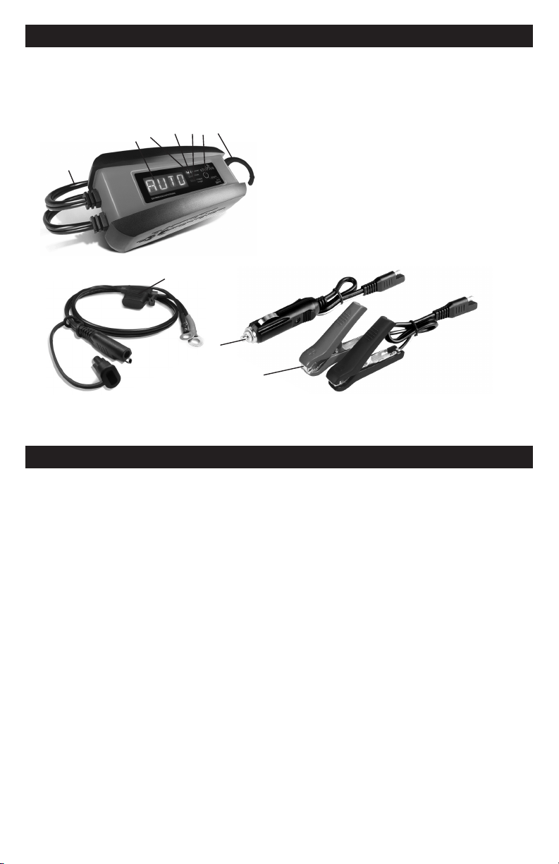
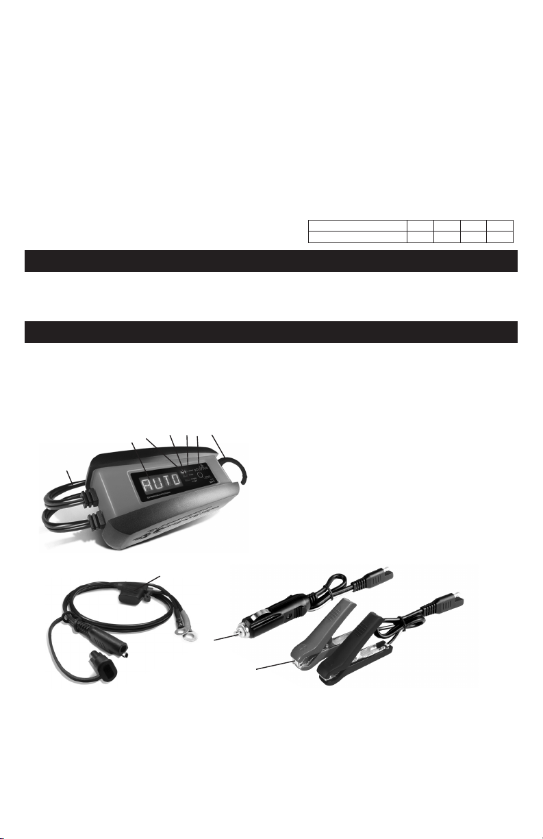
10. FEATURES
10
9
1. AC Power cord
2. Digital display
3. Connected (blue) LED
4. Trouble (red) LED
5. Charging/Charged (green) LED
6. Display/ON button
7. Hook attachment
8. Ring terminal quick-connect with 7.5A fuse
9. 12V accessory plug quick-connect
with 5A fuse
10. Battery clamp quick-connect
8
3
5
4
7
6
2
1
NOTE: Connecting the SPC3 charger to the internet requires the Schulink G1 Gateway,
included when purchased as a kit, or sold separately.
11. CONTROL PANEL
DIGITAL DISPLAY
The digital display indicates the
status of the battery and charger. See
Display Messages for a complete list of
messages.
NOTE: For energy efciency during
charging, the display will go into sleep
mode and will not display any messages.
To turn the display back on, press the
display/ON button.
LED INDICATORS
BLUE (CONNECTED) LED ashing –
The charger is connected to the SEC cloud,
through the Gateway, but not yet registered.
BLUE (CONNECTED) LED solid –
The charger is connected to an active
user account.
GREEN (CHARGING/CHARGED) LED
solid – The charger is charging the battery.
GREEN (CHARGING/CHARGED) LED
pulsing – The battery is fully charged and
the charger is in maintain mode.
RED (TROUBLE) LED solid – The battery
is bad. See Aborted Charge section.
• 9 •
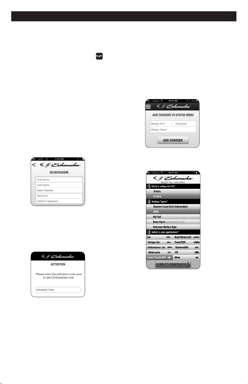
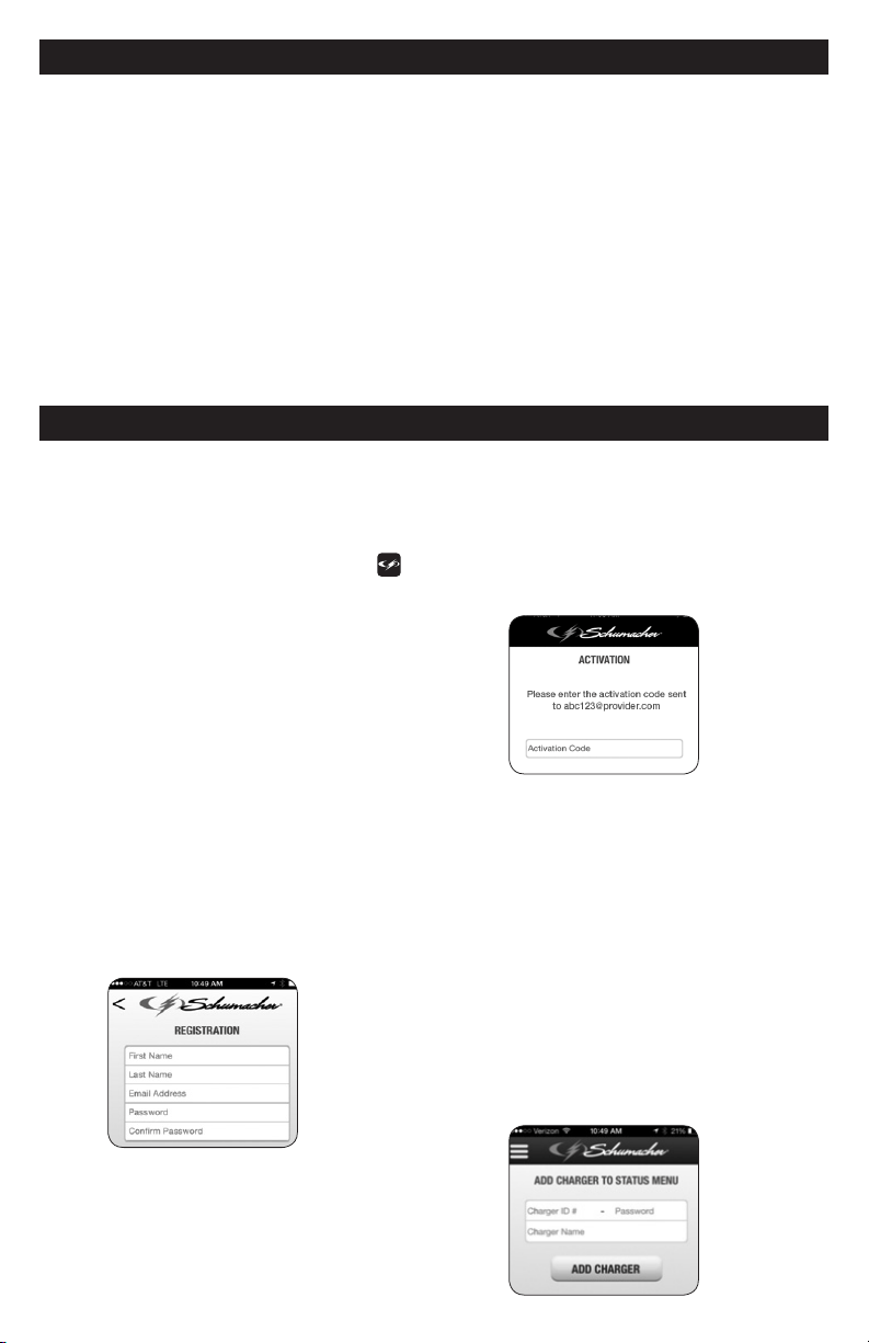
12. INSTALLING THE APP
1. Before you begin, have your charger ID
card on hand.
2. Download and install the App:
“Schumacher Electric” (Apple store)
or “Schumacher Connected Charger”
(Google Play). Look for the
icon.
NOTE: For Apple devices, requires iOS 7.0
or later; Android devices, OS 4.0 or later.
3. Open the App on your mobile device.
4. When using the App for the rst time,
you must complete
Registration and Activation.
5. Registration: Fill in all of the elds
on the Registration screen. Create
your password. Your password must
be between 8 and 24 characters, and
must contain characters from three of
the following four groups: lowercase
letters, uppercase letters, numbers, and
non-alphanumeric characters (! # $ % &
@ *). At least 6 of those characters may
occur only once in the password.
6. An activation code will be sent to the
email address you provided when
you registered. Enter this code on
the Activation screen. NOTE: the
Activation code must be entered
within two hours. If not activated,
you will have to reload the app.
7. After the Activation process is
complete, proceed to Add Charger to
Status. Enter the charger’s ID number
and password, found on the side of the
charger or on the charger’s ID card.
The password will be the last two digits
after the dash in the charger ID number
(SCHXXXXXXXX-XX). Next, create
and enter a name for your charger
(choose any name; it can be changed
later). Click on Add Charger. The App
can accommodate up to 12 different
chargers.
8. Proceed to the Charger Survey
screen. Fill in the Survey elds, and
then click on Complete Registration.
NOTE: The information you provide
in the Survey form does not affect the
charger’s operation or the type of battery
it can charge.

• 10 •
13. SETTING UP THE WIRELESS CONNECTION
NOTE: Connecting the SPC3 charger
to the internet requires the Schulink G1
Gateway, included when purchased as a
kit, or sold separately. The Gateway
allows you manage up to 12 different
chargers.
The G1 Gateway and the SPC3 charger
communicate with each other by radio
waves, the same way a cordless phone
works. Interference can affect the
allowable distance between the gateway
and charger. To make setup easier when
installing the Gateway/Charger/App, it is
best to have the charger in the same room
as the Gateway.
1. Install the app and complete the
registration and activation.
2. Install the gateway
Place the G1 Gateway in a suitable
location. Helpful tips:
• The G1 Gateway covers an area of
about 40 ft. in radius in a typical wood-
construction home. Place the G1
Gateway in a location so that this 40
ft. circle covers the area in which the
SPC3 charger will be used.
• If you are using multiple SPC3
chargers and need to cover a larger
area, consider using two or more
G1 Gateways to provide adequate
coverage.
• For best wireless coverage, place
the G1 Gateway at least 3 ft. above
ground level.
• Large concentrations of metal, such
as home appliances, water heaters,
replace hoods, or automobiles create
a “radio shadow”, which can disrupt
wireless connectivity. Avoid placing
the G1 Gateway near such obstacles,
or having such objects between the
gateway and the charger.
• If a wireless connection cannot be
established between the G1 Gateway
and a SPC3 charger, try moving the
gateway or the charger a few feet
horizontally or vertically. This may
shift the “radio shadows” and enable
connectivity.
Plug the provided Ethernet cable into
an unused output port on your router.
If you are unfamiliar with your router,
please refer to its manual. Next,
plug the provided AC adaptor into its
connection on the Gateway and into
a live AC outlet. Raise the antenna
on the gateway to a 90° position.
The Gateway’s LED should turn red
and then green after a few minutes,
indicating it is working and connected
to the Cloud. If the LED remains red,
try another open port on the router.
If it does not eventually turn green,
your router maybe incompatible with
the Gateway. When set up, the green
LED on the Gateway may occasionally
ash; this is normal and indicates it is
communicating with the Cloud.
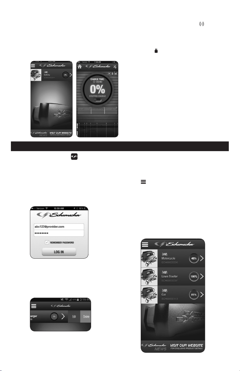
3. Plug the charger into a live grounded
120V AC outlet. The blue CONNECTED
LED on the charger will turn solid. If
the blue LED ashes for more than 30
seconds, refer to Troubleshooting. Your
mobile device should show a screen
similar to the image (A).
A B
4. Tapping the gray bar above the
motorcycle icon will bring you to
screen (B). The blue icon
indicates
radio communication between the
gateway and the charger. If the radio
connection is not present, the icon
turns gray. The green AC plug icon
indicates the charger is plugged into
an AC power outlet. When no AC
power is detected, the icon turns gray.
5. Disconnect the charger from the AC
power and move it to the area where
it will be connected to the battery.
Before connecting the charger to
the battery, make sure there is no
interference in the radio connection
between the gateway and the charger.
6. Connect your charger, following the
precautions listed in Sections 6 and
7. Plug the charger in a live grounded
120V AC outlet.
• 11 •
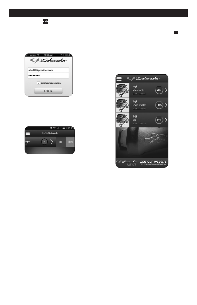
14. USING THE APP TO CONTROL THE CHARGER
• Open the
App on your mobile
device. Log in, using the email address
and password that you provided when
you registered. Selecting Remember
Password
allows you to quickly log in
next time. If you forget your password,
see Resetting your Password.
• The HOME screen shows all
connected chargers. Swipe left on
a charger to bring up the screen to
delete the charger or edit the charger
information.
• Use the arrow on the right to select the
charger you want to monitor.
• The three short horizontal bars
bring up a menu to add additional
chargers, review terms and conditions,
or logout of the App.
• The Schumacher banner at the bottom of
the screen links you to the Schumacher
website. For help with installation and
setup, view the instructional video on
batteryextenders.com.
• 12 •
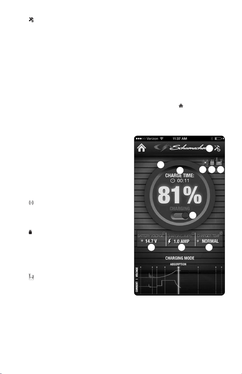
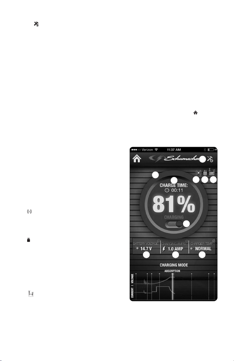
THE STATUS SCREEN
A.
Software Update Available –
Indicates that a software update is
available for the charger itself (not the
App). Tapping the icon will load the new
software from the Cloud and restart the
charger. This may take several minutes.
Do not unplug the charger while the
update is in progress.
B. Charge Indicator Ring – The color
of this ring and the amount of the
circle that is lled indicates the
charge level. A completely green ring
indicates the battery is fully charged.
This corresponds to the percentage
displayed in the center.
C. Charge Time – The amount of time
needed to charge the battery when it
was rst connected.
D. Charge Pause Switch – The sliding
switch starts or pauses the charging
process. The current status is shown
above the switch. You can pause the
charge while watching the voltage drop
to see if there is a power draw from the
battery. The charging process will not be
reset unless the charger is unplugged
and plugged in again. NOTE: This
charger is also a maintainer and it is not
necessary to stop the charging process;
the charger will automatically switch to
maintenance mode when the battery is
fully charged.
E. Connected to the Cloud – When
blue, this indicates the charger is
connected to the Cloud. When the
charger is not connected to the Cloud,
the icon turns gray.
F. Connected to AC – Indicates the
charger is plugged into a live 120V AC
outlet. If the charger is unplugged from
the AC, the charger will power itself off
of the battery for ve minutes, sending
out a loss of power signal to the app.
When no AC power is detected, the
icon turns gray.
G. Connected to Battery – When
green, indicates that the battery is
properly connected to the charger.
When clamps are reversed or not
connected, the icon turns gray.
H. Battery Voltage – Shows battery
voltage. This voltage varies throughout
the charging cycle, but gives an
indication of the health of the battery.
If the value goes below 12.5V during
Float or Maintain modes, this could
indicate excessive draw on the
battery by the vehicle or the battery
approaching the end of its life.
I. Charge Amps – Shows the current the
charger is putting into the battery.
J. Charger Temperature – Shows the
charger’s temperature status. The
charger will automatically lower
the charge current if it detects the
temperature is higher than normal.
Use the house icon to return to the
HOME screen.
NOTE: The App will time out after 15
minutes of inactivity, and you will need to
log in again to use it.
A
B
C
D
E F G
H I J
• 13 •
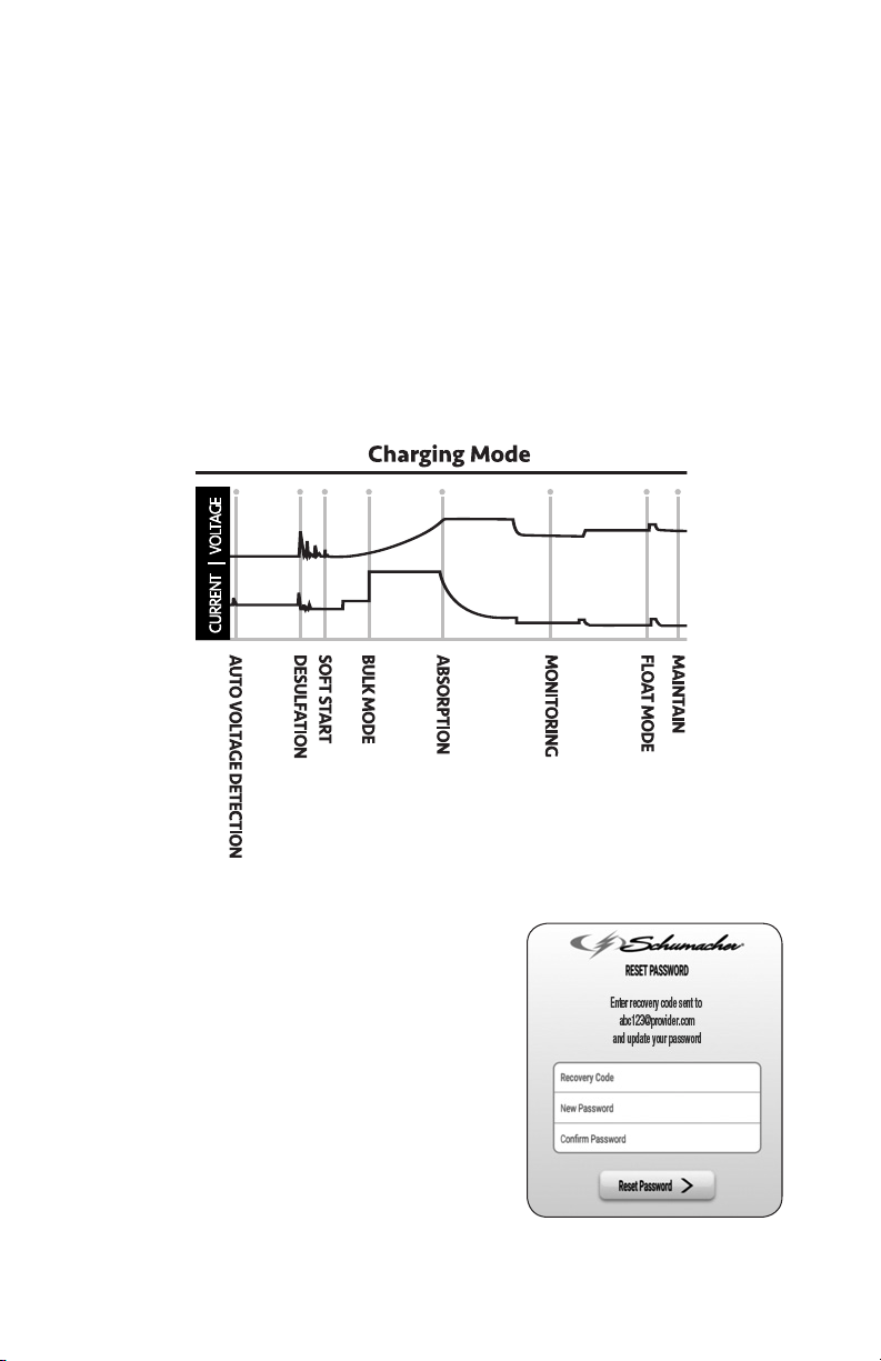
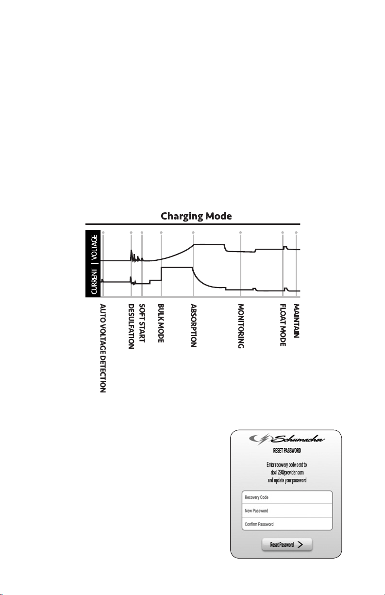
CHARGING MODE
Charging mode lets you follow the
progress through the 8 stages of charging:
1. Auto Voltage Detection – In this mode,
a battery is connected to the charger
and the charger is determining
whether it is a 6V or 12V battery.
2. Desulfation – The charger has
detected an unhealthy, sulfated battery
and has begun a special process to try
to remove the sulfation and possibly
restore the battery.
3. Soft Start – The charger has
determined the battery voltage and
gently starts to charge the battery by
slowly increasing the charging current.
4. Bulk Mode – The majority of the
energy delivered to the battery is
done in this mode. When the charger
exits this mode, the battery will be at
approximately 80% recharged.
5. Absorption Mode – This mode nishes
the charge of the battery by holding
the battery voltage constant until the
current tapers off.
6. Monitoring Mode – The battery is
allowed to rest for 24 hours before
checking for a loss of charge.
7. Float Mode – The charger is replacing
energy the battery has lost through
self-discharge or idle draw of the
attached vehicle.
8. Maintain – The charger checks the
battery every 12 hours and puts the
charger into oat mode to replenish
lost energy from the battery.
RESETTING YOUR PASSWORD
1. In the log in screen, press Forgot
Password. A recovery code will be
sent to the email address
you provided during registration.
2. Enter the recovery code.
3. Enter your new password.
4. Reenter the new password, for
conrmation.
5. Click Reset Password to complete the
process.
NOTE: Selecting Remember Password
allows you to quickly log in next time.

• 14 •
15. OPERATING THE CHARGER
USING THE CHARGER
WITHOUT THE INTERNET
The charger itself is a stand-alone device
and will function as a battery charger/
maintainer without an internet connection.
However, without a Cloud connection, the
App will not reect the charging progress.
IMPORTANT: Do not start the vehicle with
the charger connected to the AC outlet,
or it may damage the charger and your
vehicle.
WARNING: This charger is equipped with
an auto-start feature. Current is supplied
to the battery clamps before a battery is
connected, and the clamps will spark if
touched together.
NOTE: This charger is also a maintainer,
and can be left on the battery of vehicles
that are being stored.
USING THE QUICK-CONNECT
CABLE CONNECTORS
Connect any of the three output cable
assemblies to the charger in a matter of
seconds.
IMPORTANT: Use the charger with only
one connector at a time. Do not connect
accessory cables together. This will cause
reverse polarity and damage the charger
and battery.
BATTERY CLAMP QUICK-CONNECT
Charging a Battery in the Vehicle
1. Turn off all the vehicle’s accessories.
2. Do not close the hood, battery
compartment, etc.
3. Clean the battery terminals.
4. Place the charger on a dry, non-
ammable surface, or use the
convenient hook attachment to hang
the unit safely outside the work area.
5. Lay the AC/DC cables away from any
fan blades, belts, pulleys and other
moving parts.
6. Connect the battery, following the
precautions listed in sections 6 and 7.
7. Connect the charger to a live
grounded 120V AC outlet.
8. The blue CONNECTED LED will light,
indicating that the charger is connected
to the Gateway and communicating
with an active user account.
9. When charging starts, the green LED
will be solid, and the display will scroll
“ANALYZING BATTERY” while the
charger determines that the battery is
properly connected, the condition of
the battery, and whether the battery is
6V or 12V.
10. Monitor the progress of the charge by
pressing the display button on the front
of the unit. When the battery is fully
charged, the green LED will pulse.
11. When charging is complete,
disconnect the charger from the AC
power, remove the clamps from the
vehicle’s chassis, and then remove
the clamp from the battery terminal.
Charging a Battery Outside of the Vehicle
1. Place battery in a well-ventilated area.
2. Clean the battery terminals.
3. Connect the battery, following the
precautions listed in sections 6 and 7.
4. Connect the charger to a live grounded
120V AC outlet.
5. The blue CONNECTED LED will light,
indicating that the charger is connected
to the Gateway and communicating
with an active user account.
6. When the charger starts, the green
LED will be solid, and the display will
scroll “ANALYZING BATTERY” while
the charger determines if the battery
is properly connected, the condition of
the battery, and whether the battery is
6V or 12V.
7. Monitor the progress of the charge by
pressing the display button on the front
of the unit. When the battery is fully
charged, the green LED will pulse.
8. When charging is complete, disconnect
the charger from the AC power,
disconnect the negative clamp,
and nally the positive clamp.
RING TERMINAL QUICK-CONNECT
The ring connectors permanently attach to
the battery, providing easy access to quickly
connect the charger to your battery. This
application is appropriate for motorcycles,
lawn tractors, ATVs and snowmobiles.
1. To permanently attach to a battery,
loosen and remove each nut from the
bolt at the battery terminal.
IMPORTANT: Loss of vehicle settings can
occur. Check vehicle owners manual for
specic information.
2. Connect the red POSITIVE connector
ring to the POSITIVE battery terminal.
3. Connect the black NEGATIVE connector
ring to the NEGATIVE battery terminal.
4. Replace and tighten the nuts to secure.
5. Connect the cable to the end of the
charger output cord. Take care to keep
the wires and plug away from metal
and moving parts.
6. Plug the charger power cord into a live
grounded 120V AC outlet.

• 15 •
12V ACCESSORY PLUG
QUICK-CONNECT
Charge or maintain your battery without
lifting the hood. NOTE: The charger itself
must be disconnected when the vehicle
is in use.
1. Connect the end of the 12V accessory
plug quick-connect to the charger.
2. Insert the 12V accessory plug into the
12V accessory outlet.
3. Route the power cord from the charger
through the vehicle’s open window.
4. Plug the charger power cord into a live
grounded 120V AC outlet.
5. If the vehicle’s ignition key has to be
on in order for the accessory outlet
to supply/receive power, turn the key,
without starting the engine. Consult
your vehicle owners manual for
instructions on how to make the 12V
outlet live, without drawing excessive
power.
AUTOMATIC CHARGING MODE
When an automatic charge is performed,
the charger switches to the maintain mode
automatically after the battery is charged.
BATTERY CONNECTION INDICATOR
If the charger does not detect a properly
connected battery, charging will not start
and the digital display will show one
of two messages. If the display shows
“CONNECT BATTERY”, make sure the
charger is connected to the battery and the
connection points are clean and making
a good connection. If the display shows
“WARNING CLAMPS REVERSED”,
unplug the charger from the AC outlet,
reverse the connections at the battery,
and then plug the charger back in.
CHARGE COMPLETION AND MAINTAIN
MODE (Float Mode Monitoring)
Charge completion is indicated by the green
LED pulsing and the digital display scrolling
“FULLY CHARGED AUTO MAINTAINING”.
This means that the charger has stopped
charging and has switched to the Maintain
Mode of operation. NOTE: If the charger
has to provide its maximum maintain
current (1.8A) for a continuous 12 hour
period, it will go into Abort Mode (see
Aborted Charge section). This is usually
caused by a load on the battery, or the
battery could be bad. Make sure there are
no loads on the battery. If there are, remove
them. If there are none, have the battery
checked or replaced.
MAINTAINING A BATTERY
This unit maintains both 6 and 12 volt
batteries, keeping them at full charge. It
can charge small batteries and maintain
both small and large batteries. If you are
maintaining a fully charged large battery,
you are properly utilizing the battery
charger. However, if you use this battery
charger to charge a large battery, such
as a marine deep-cycle battery that was
not fully charged, you may not get the
battery’s full capacity. Therefore, we do
not recommend charging a large battery
with this unit.
NOTE: The maintain mode technology
allows you to safely charge and maintain
a healthy battery for extended periods
of time. However, problems with the
battery, electrical problems in the
vehicle, improper connections or other
unanticipated conditions could cause
excessive current draws. As such,
occasionally monitoring your battery and
the charging process is required.
BATTERY CHARGING TIMES
CCA = Cold Cranking Amps Ah = Amp Hour RC = Reserve Capacity
BATTERY SIZE/RATING CHARGE TIME (3A)
SMALL BATTERIES
Motorcycle, garden tractor, etc.
6-12 Ah 1½-2½ h
12-32 Ah 2½-7 h
CARS AND
TRUCKS
200-315 CCA 40-60 RC 7½-9½ h
315-550 CCA 60-85 RC 9½-12¼ h
550-1000 CCA 85-190 RC MAINTAIN ONLY
MARINE/DEEP-CYCLE
80 RC 11¾ h
140 RC MAINTAIN ONLY
160 RC MAINTAIN ONLY
180 RC MAINTAIN ONLY
Times are based on a 50% discharged battery and may change, depending on
age and condition of battery.

• 16 •
DESULFATION MODE
If the battery is left discharged for an
extended period of time, it could become
sulfated and not accept a normal charge.
If the charger detects a sulfated battery,
the charger will switch to a special mode
of operation designed for such batteries.
If successful, normal charging will resume
after the battery is desulfated. Desulfation
could take up to 8 hours. If desulfation
fails, charging will abort, the red LED will
light, and the display will scroll “CHARGE
ABORTED-BAD BATTERY”.
ABORTED CHARGE
If charging cannot be completed normally,
charging will abort. When charging aborts,
the charger’s output is shut off, the red
LED will light, and the display will scroll
“CHARGE ABORTED-BAD BATTERY”.
Do not continue attempting to charge this
battery. Have it checked or replaced.
16. DISPLAY MESSAGES
“CONNECT BATTERY”
(Blue LED only, solid) – Plugged into the
AC outlet without the clamps connected to
a battery.
“WARNING CLAMPS REVERSED”
(Blue LED only, solid) – Plugged into the
AC outlet and the clamps are connected
backwards to a 6V or 12V battery.
“ANALYZING BATTERY”
(Green LED solid) – Plugged into the AC
outlet, and when rst connected to a 6V
or 12V battery correctly.
“CHARGING 12V – XX%”
(Green LED solid) – Plugged into the AC
outlet, correctly connected and charging a
12V battery.
“CHARGING 6V – XX%”
Green LED solid) – Plugged into the AC
outlet, correctly connected and charging a
6V battery.
“FULLY CHARGED AUTO MAINTAINING”
(Green LED pulsing) – Plugged into a live
grounded AC outlet and correctly connected
to a fully charged 6V or 12V battery.
“CHARGE ABORTED-BAD BATTERY”
(Red LED solid) – Circumstances that could
cause an Abort situation during charging:
• The battery is severely sulfated or has a
shorted cell and can’t reach a full charge.
• The battery is too large or there is a
bank of batteries and it doesn’t reach full
charge within a set time period.
Circumstances that could cause an Abort
situation during maintain:
• The battery is severely sulfated or has a
weak cell and will not hold a charge.
• There is a large draw on the battery and
the charger has to supply its maximum
maintain current for a 12 hour period to
keep the battery at full charge.
17. MAINTENANCE AND CARE
A minimal amount of care can keep your
battery charger working properly for years.
• Clean the clamps each time you are
nished charging. Wipe off any battery
uid that may have come in contact with
the clamps, to prevent corrosion.
• Occasionally cleaning the case of the
charger with a soft cloth will keep the
nish shiny and help prevent corrosion.
• Coil the input and output cords neatly
when storing the charger. This will help
prevent accidental damage to the cords
and charger.
• Store the charger unplugged from the AC
power outlet.
• Store inside, in a cool, dry place. Do not
store the clamps clipped together, on or
around metal, or clipped to the cables.

• 17 •
18. TROUBLESHOOTING
PROBLEM POSSIBLE CAUSE SOLUTION
The charger’s blue
CONNECTED LED does
not light, but turns solid
when moved closer to the
gateway.
Indicates either a radio
interference problem or a
range problem.
Make sure there are no large metal
objects between the gateway and
charger. Bring the gateway and
charger closer together. Try using
a longer cable (up to 100 feet) to
move the gateway closer to the
charger. If this cannot be done,
try raising or lowering both the
gateway and or the charger, or
moving them around slightly. Both
may get better reception in different
places within the same room.
The charger’s blue
CONNECTED LED
ashes.
The SPC3 charger is not
registered.
Complete registration and
activation. See Section 12 for
instructions.
The charger will not turn on
when properly connected.
AC outlet is dead.
Poor electrical connection.
Check for open fuse or circuit
breaker supplying AC outlet.
Check power cord and extension
cord for loose tting plug.
I cannot select a 6V or 12V
setting.
The charger is equipped
with Auto Voltage Detection,
which automatically detects
the voltage and charges the
battery.
No problem; this is normal.
The display scrolls
“CONNECT BATTERY”.
The clamps are not making a
good connection.
The fuse is bad.
Check for poor connection at
battery and frame.
Replace the in-line fuse for the
ring connector or 12V accessory
plug connector.
Green LED is solid and the
display scrolls “ANALYZING
BATTERY”.
The charger needs to check
the condition of the battery.
The green LED will be solid
when the charger is checking the
condition of the battery. This is
normal.
Charging a 12V battery,
but the display shows
“CHARGING 6V”.
Battery may be extremely
discharged.
No problem; the charger will
eventually recognize battery as
12V and charge completely.
Red LED is solid and the
display scrolls “CHARGE
ABORTED-BAD BATTERY”.
The battery is bad.
The battery is too large for
the charger.
Disconnect charger from the
AC outlet and then remove the
clamps. Do not continue to try
to charge the battery. Have the
battery checked or replaced.
You need a charger with a higher
amp rate.

• 18 •
19. BEFORE RETURNING FOR REPAIRS
If these solutions do not eliminate the problem, or for more information
about troubleshooting, contact customer service for assistance:
www.batterychargers.com
or call 1-800-621-5485
Monday-Friday 7:00am to 5:00pm CST
For REPAIR OR RETURN, contact Customer Service at 1-800-621-5485. DO NOT SHIP
UNIT until you receive a RETURN MERCHANDISE AUTHORIZATION (RMA) number
from Customer Service at Schumacher Electric Corporation.
20. SPECIFICATIONS
Input Voltage ................................................................................120V AC @ 60Hz, 0.91A
Output Voltage .......................................................6V or 12V, with Auto Voltage Detection
Output Current Rating .......................................................................... 2A @ 6V; 3A @12V
21. REPLACEMENT PARTS / ACCESSORIES
Battery clamps (quick-connect).....................................................................3899002636Z
Ring connectors (quick-connect) .................................................................2299002042Z
12V accessory plug (quick-connect) ............................................................. 3899001401Z
G1 Gateway kit (includes AC charger and Ethernet cable) ............................. 940261198
G1 Gateway only ..........................................................................................2200992769Z
AC wall charger for G1 Gateway ......................................................................93026939Z

• 19 •
22. LIMITED WARRANTY
SPC3 CHARGER
WARRANTY NOT VALID IN MEXICO.
SCHUMACHER ELECTRIC CORPORATION, 801 BUSINESS CENTER DRIVE,
MOUNT PROSPECT, IL 60056-2179, MAKES THIS LIMITED WARRANTY TO THE
ORIGINAL RETAIL PURCHASER OF THIS PRODUCT. THIS LIMITED WARRANTY
IS NOT TRANSFERABLE OR ASSIGNABLE.
Schumacher Electric Corporation (the “Manufacturer”) warrants this battery charger
for two (2) years from the date of purchase at retail against defective material or
workmanship that may occur under normal use and care. If your unit is not free from
defective material or workmanship, Manufacturer’s obligation under this warranty is
solely to repair or replace your product with a new or reconditioned unit at the option
of the Manufacturer. It is the obligation of the purchaser to forward the unit, along with
proof of purchase and mailing charges prepaid to the Manufacturer or its authorized
representatives in order for repair or replacement to occur.
Manufacturer does not provide any warranty for any accessories used with this product
that are not manufactured by Schumacher Electric Corporation and approved for use
with this product. This Limited Warranty is void if the product is misused, subjected to
careless handling, repaired, or modied by anyone other than Manufacturer or if this
unit is resold through an unauthorized retailer.
Manufacturer makes no other warranties, including, but not limited to, express, implied or
statutory warranties, including without limitation, any implied warranty of merchantability
or implied warranty of tness for a particular purpose. Further, Manufacturer shall
not be liable for any incidental, special or consequential damage claims incurred by
purchasers, users or others associated with this product, including, but not limited to,
lost prots, revenues, anticipated sales, business opportunities, goodwill, business
interruption and any other injury or damage. Any and all such warranties, other than the
limited warranty included herein, are hereby expressly disclaimed and excluded. Some
states do not allow the exclusion or limitation of incidental or consequential damages or
length of implied warranty, so the above limitations or exclusions may not apply to you.
This warranty gives you specic legal rights and it is possible you may have other rights
which vary from this warranty.
THIS LIMITED WARRANTY IS THE ONLY EXPRESS LIMITED WARRANTY AND THE
MANUFACTURER NEITHER ASSUMES OR AUTHORIZES ANYONE TO ASSUME
OR MAKE ANY OTHER OBLIGATION TOWARDS THE PRODUCT OTHER THAN
THIS WARRANTY.
Schumacher
®
is a registered trademark
of Schumacher Electric Corporation.
Battery Extender
®
is a trademark
of Auto Meter Products, Inc.

• 20 •
1. INSTRUCCIONES IMPORTANTES DE SEGURIDAD
POR FAVOR CONSERVE ESTE
MANUAL DEL USUARIO Y LEALO
ANTES DE CADA USO. En este manual
le explica cómo utilizar el cargador de
manera segura y conable. Por favor,
lea y siga las siguientes instrucciones y
precauciones.
NOTA: El cargador en sí es un dispositivo
autónomo y funcionará como un cargador/
mantenedor de batería sin conexión a
Internet. Sin embargo, sin una conexión
a la nube, la aplicación no reejará el
progreso de la carga.
1.1 GUARDE ESTAS INSTRUCCIONES –
Este manual contiene instrucciones
operativas y de seguridad de importancia.
1.2 Manténgase fuera del alcance de los niños.
1.3 No exponga el cargador a la lluvia o a la
nieve.
1.4 El uso de un accesorio no recomendado
o suministrado por Schumacher
®
Electric
Corporation puede provocar riesgo de
incendio, descarga eléctrica o lesiones a
personas.
1.5 Para reducir el riesgo de daños al
enchufe o cable eléctrico, jale del enchufe
en lugar de jalar del cable al desconectar
el cargador.
1.6 No se debe utilizar un alargador a menos
que resulte absolutamente necesario. El
uso de un alargador inadecuado puede
provocar riesgo de incendio o descarga
eléctrica. En caso de que deba utilizarse
un alargador, asegúrese de que:
• Los pasadores en el enchufe del
alargador posean el mismo número,
tamaño y forma que aquellos presentes
en el enchufe del cargador.
• El alargador se encuentre correctamente
conectado y en buenas condiciones
eléctricas
• El tamaño del cable sea lo
sucientemente extenso para el
amperaje en CA del cargador como se
especica en sección 8.
1.7 No utilice el cargador si el mismo posee
un enchufe o cable dañado; substituya el
cable o el enchufe inmediatamente por
una persona calicada en el ramo.
1.8 No utilice el cargador si el mismo recibió
un golpe fuerte, si se cayó o si sufrió
daños de cualquier otra forma; hágalo
revisar por una persona capacitada que
efectúe reparaciones.
1.9 No desarme el cargador; hágalo revisar
por una persona capacitada que efectúe
reparaciones cuando necesite servicio
de mantenimiento o una reparación.
Volver a ensamblar el cargador en forma
incorrecta puede provocar riesgo de
incendio o descarga eléctrica.
1.10 Para reducir el riesgo de descarga
eléctrica, desenchufe el cargador del
tomacorriente antes de intentar llevar a
cabo cualquier actividad de mantenimiento
o limpieza. El simple apagado de los
controles no reducirá este riesgo.
1.11 ADVERTENCIA: RIESGO DE GASES
EXPLOSIVOS.
a. RESULTA PELIGROSO TRABAJAR EN
FORMA CERCANA A UNA BATERÍA DE
PLOMO. LAS BATERÍAS GENERAN
GASES EXPLOSIVOS DURANTE
SU NORMAL FUNCIONAMIENTO.
POR ESTE MOTIVO, RESULTA DE
SUMA IMPORTANCIA QUE SIGA LAS
INSTRUCCIONES CADA VEZ QUE
UTILIZA EL CARGADOR.
b. Para reducir el riesgo de explosión de
una batería, siga estas instrucciones y
aquellas publicadas por el fabricante
de la batería y por el fabricante de
cualquier equipo que intente utilizar
en la proximidad de la batería. Revise
las pautas de precaución en estos
productos y en el motor.
1.12 Conforme a la Propuesta 65 de California,
este producto contiene químicos de los
cuales en el Estado de California se
tiene conocimiento que provocan cáncer
y malformaciones congénitas u otras
lesiones reproductivas. Lávese las manos
después de usar.
2. PRECAUCIONES DE SEGURIDAD PERSONAL
2.1 Considere la idea de que alguna persona
se encuentre cerca suyo para poder
ayudarlo cuando trabaje en forma
cercana a una batería de plomo-ácido.
2.2 Cuente con una gran cantidad de agua
potable y jabón a mano en caso de que el
ácido de la batería tenga contacto con su
piel, ropa u ojos.
2.3 Utilice protección visual y corporal completa,
incluyendo gafas de seguridad y prendas
de protección. Evite tocar sus ojos mientras
trabaje en forma cercana a la batería.
2.4 Si el ácido de la batería tiene contacto
con su piel o su ropa, lave de inmediato
el área afectada con agua y jabón. En
caso de que ingrese ácido en un ojo,
sumerja el mismo de inmediato bajo
agua potable corriente por al menos 10
minutos y obtenga atención médica en
forma inmediata.

• 21 •
2.5 NUNCA fume o permita la presencia de
chispas o llamas en la proximidad de una
batería o motor.
2.6 Tenga especial cuidado para reducir el
riesgo de dejar caer una herramienta
de metal sobre la batería. Esto podría
provocar chispas o un cortocircuito en la
batería o en cualquier otra pieza eléctrica
que podría provocar una explosión.
2.7 No utilice elementos personales de metal
tales como anillos, pulseras, collares y
relojes al trabajar con una batería de
plomo-ácido. Una batería de plomo-
ácido puede producir una corriente de
cortocircuito lo sucientemente elevada
como para soldar un anillo o provocar
efectos similares sobre el metal,
causando una quemadura de gravedad.
2.8 Utilice el cargador de la batería, en
baterías recargables de 6 y 12V de
plomo-ácido, GEL y tipo AGM, con
recomienda usar capacidad de la batería
de 12Ah (6V) y 12-59Ah (12V). Este
cargador no está destinado a suministrar
energía a sistemas eléctricos de baja
tensión más que en una aplicación de
un motor de arranque. No utilice este
cargador de batería para cargar baterías
de pila seca que por lo general se utilizan
con artefactos domésticos. Estas baterías
podrían explotar y provocar lesiones a
personas o daño a la propiedad.
2.9 NUNCA cargue una batería congelada.
3. PREPARACIÓN PARA LA CARGA
3.1 Si resulta necesario extraer la batería
del vehículo para cargarla, siempre retire
el terminal con descarga a tierra en
primer lugar. Asegúrese de que todos los
accesorios en el vehículo se encuentren
apagados para evitar la formación de
arcos eléctricos.
3.2 Asegúrese de que el área que rodea a
la batería se encuentre bien ventilada
mientras se carga la batería.
3.3 Limpie los terminales de la batería antes
de cargar la batería. Durante la limpieza,
evite que la corrosión producida por aire
tenga contacto con sus ojos.
3.4 Agregue agua destilada a cada pila
hasta que el ácido de la batería alcance
el nivel especicado por el fabricante de
la batería. No provoque derrames. En lo
que concierne a baterías que no cuentan
con tapas extraíbles para pilas, tales
como baterías de plomo-ácido reguladas
por válvulas (VRLA, por sus siglas
en inglés), siga cuidadosamente las
instrucciones de recarga del fabricante.
3.5 Controle todas las precauciones
especícas establecidas por el fabricante
de la batería al realizar la carga, así
también como los índices de carga
recomendados.
3.6 Determine la tensión de la batería
al consultar el manual del usuario
del vehículo y asegúrese de que el
interruptor de selección de la tensión de
salida se encuentre establecido en la
tensión correcta. Si el cargador posee
un índice de carga ajustable, cargue
la batería en el menor índice en primer
lugar. Para un cargador sin un interruptor
selector para voltaje de salida, determinar
el voltaje de la batería al referirse al
manual del propietario del vehículo y
asegurarse de que coincide nominal de
salida del cargador de batería.
4. UBICACIÓN DEL CARGADOR
4.1 Ubique el cargador a la mayor distancia
posible de la batería como lo permitan los
cables de CC.
4.2 Nunca ubique el cargador directamente
por encima de la batería que se carga;
los gases de la batería corroerán y
dañarán el cargador.
4.3 Nunca permita que el ácido de la batería
gotee sobre el cargador al leer el peso
especíco del electrolito o al cargar la
batería.
4.4 No utilice el cargador en un área cerrada
o restrinja la ventilación en cualquier
forma.
4.5 No ubique la batería encima del cargador.
5. PRECAUCIONES DE CONEXIÓN EN CC
5.1 Conecte y desconecte las pinzas de
salida CC. sólo después de haber
establecido todos los interruptores del
cargador a la posición de “apagado” (si
es aplicable) y de haber desconectado
el enchufe de C.A. del tomacorriente
eléctrico. Nunca permita que las pinzas
tengan contacto entre sí.
5.2 Sujete las pinzas a la batería y al chasis,
como se indica en en las secciones 6 y 7.

• 22 •
6. SIGA ESTOS PASOS CUANDO LA BATERÍA ESTÉ COLOCADA EN EL VEHÍCULO
UNA CHISPA PROVOCADA CERCA
DE LA BATERÍA PUEDE CAUSAR LA
EXPLOSIÓN DE LA BATERÍA. PARA
REDUCIR EL RIESGO DE PROVOCAR
CHISPAS CERCA DE LA BATERÍA:
6.1 Ubique los cables de C.A. y C.C. para
reducir el riesgo de daños a la cubierta,
a la puerta y a las piezas móviles o
calientes del motor.
6.2 Manténgase alejado de las paletas del
ventilador, correas, poleas y otras piezas
que podrían provocar lesiones.
6.3 Verique la polaridad de los bornes de
la batería. El borne POSITIVO (POS,
P, +) de la batería generalmente posee
un diámetro mayor al borne NEGATIVO
(NEG, N, -).
6.4 Determine qué borne de la batería
hace descarga a tierra (se encuentra
conectado) con el chasis. Si el borne
negativo hace descarga a tierra con el
chasis (como en la mayor parte de los
vehículos), ver el paso (6.5) Si el borne
positivo hace descarga a tierra con el
chasis, ver el paso (6.6).
6.5 En un vehículo con descarga a tierra
por borne negativo, conecte el gancho
POSITIVO (ROJO) del cargador de
batería al borne POSITIVO (POS, P, +)
sin descarga a tierra de la batería.
Conecte el gancho NEGATIVO
(NEGRO) al chasis del vehículo o al
bloque motor alejado de la batería. No
conecte el gancho al carburador, líneas
de combustible o cuerpos metálicos.
Conecte a una pieza metálica de calibre
grueso del marco o del bloque motor.
6.6 En un vehículo con descarga a tierra
por borne positivo, conecte el gancho
NEGATIVO (NEGRO) del cargador de
batería al borne NEGATIVO (NEG, N, -)
sin descarga a tierra de la batería.
Conecte el gancho POSITIVO (ROJO)
al chasis del vehículo o al bloque motor
alejado de la batería. No conecte al
carburador, líneas de combustible o
cuerpos metálicos. Conecte a una pieza
metálica de calibre grueso del marco o
del bloque motor.
6.7 Al desconectar el cargador, apague todos
los interruptores (en su caso), desconecte
el cable de C.A., retire el gancho del
chasis del vehículo y luego retire el
gancho del terminal perteneciente a la
batería.
6.8 Vea Instrucciones de Operación para
duración de la carga.
7. SIGA ESTOS PASOS CUANDO LA BATERÍA SE ENCUENTRE FUERA DEL VEHÍCULO
UNA CHISPA PROVOCADA CERCA
DE LA BATERÍA PUEDE CAUSAR LA
EXPLOSIÓN DE LA BATERÍA. PARA
REDUCIR EL RIESGO DE PROVOCAR
CHISPAS CERCA DE LA BATERÍA:
7.1 Verique la polaridad de los bornes de
la batería. El borne POSITIVO (POS,
P, +) de la batería generalmente posee
un diámetro mayor al borne NEGATIVO
(NEG, N, -).
7.2 Sujete al menos un cable aislado de
batería de 24 pulgadas (61 cm) de largo
con calibre 6 según el Calibre americano
de cables (AWG, por sus siglas en inglés)
al borne NEGATIVO (NEG, N, -) de la
batería.
7.3 Conecte el gancho POSITIVO (ROJO) del
cargador al borne POSITIVO (POS, P, +)
de la batería.
7.4 Ubíquese junto con el extremo libre del
cable que previamente sujetó al borne
NEGATIVO (NEG, N, -) de la batería a
la mayor distancia posible de la batería.
Luego conecte el gancho NEGATIVO
(NEGRO) del cargador al extremo libre
del cable.
7.5 No se ubique en posición frontal a la
batería al realizar la conexión nal.
7.6 Al desconectar el cargador, siempre
hágalo en forma inversa al procedimiento
de conexión y realice la primera conexión
tan lejos de la batería como sea posible.
7.7 Una batería marina (para barcos) se
debe retirar y cargar en tierra. Para
realizar una carga a bordo se necesitan
equipamientos especialmente diseñados
para uso marino.
8. CONEXIONES A TIERRA Y ENERGÍA DE CA
8.1 Este cargador de batería está destinado a
un uso en un circuito con tensión nominal
de 120 V CA. El enchufe se debe conectar
a un tomacorriente adecuadamente
instalado y que cuente con descarga
a tierra de acuerdo con todas las
ordenanzas y códigos. Los pasadores del
enchufe deben adaptarse al receptáculo
(tomacorriente). No utilizar con un sistema
que no posea descarga a tierra.
• 23 •
8.2 PELIGRO: Nunca altere el cable o
enchufe de C.A. suministrado, si no se
ajusta al tomacorriente, haga instalar un
tomacorriente adecuado con descarga
a tierra por medio de un electricista
capacitado. Una conexión inadecuada
puede provocar un riesgo de descarga
eléctrica o electrocución.
NOTA: De acuerdo a las Leyes
Canadienses, el uso de un enchufe
adaptador no es permitido en el Canada.
El uso de un enchufe como adaptador
no se recomienda y no debe ser utilizado
Estados Unidos.
8.3 USO DE UN CABLE DE EXTENSIÓN
El uso de una extensión no se
recomienda. Si debe usar una extensión,
siga estas pautas:
• Las clavijas del enchufe del cable de
extensión debe ser el mismo número,
tamaño y forma que las del enchufe del
cargador.
• Asegúrese de que el cable de extensión
esté conectado correctamente y en
buenas condiciones eléctricas.
• El tamaño del cable debe ser lo
sucientemente extenso para el calibre
de amperios del cargador de CA, como
se especica a continuación:
Longitud del cable (pies)
25 50 100 150
Calibre del cable AWG*
18 18 18 16
9. INSTRUCCIONES DE MONTAJE
9.1 Desenrede todos los cordones y extienda
los cables antes de usar el cargador de
baterías.
9.2 Conecte las tres partes de la Gateway
(cargador de pared, Gateway y de cable
Ethernet).
10. CARACTERÍSTICAS
10
9
1. Cable de alimentación de CA
2. Pantalla digital
3. LED Conectado (azul)
4. LED Problema (rojo)
5. LED Carga / Cargado (verde)
6. Botón de pantalla digital / ON
7. Accesorio de gancho
8. Conectores de argolla (conexión rápida)
con fusible 7,5A
9. Conector de 12V (conexión rápida) con
fusible 5A
10. Pinzas de batería (conexión rápida)
8
3
5
4
7
6
2
1
NOTA: Conexión del cargador SPC3 a Internet requiere la Schulink G1 Gateway, incluido
cuando se compra como un kit, o se vende por separado.
• 24 •
11. PANEL DE CONTROL
PANTALLA DIGITAL
La pantalla digital indica la condición de
la batería y el cargador. Vea la sección de
Muestra de Mensajes para obtener una
lista completa de los mensajes.
NOTA: Para la eciencia energética
durante la carga, la pantalla entra en el
modo de suspensión y no se mostrará
cualquiera mensaje. Para activar la
pantalla, pulse el botón de pantalla / ON.
INDICADORES LED
LED AZUL (CONECTADO) intermitente –
El cargador está conectado a la nube de
la SEC, a través de la Gateway, pero aún
no se ha registrado.
LED AZUL (CONECTADO) sólido –
El cargador está conectado a una cuenta
de usuario activo.
LED VERDE (CARGA / CARGADA)
sólido – El cargador está cargando la
batería.
LED VERDE (CARGADA /
MANTENIMIENTO) pulsante – La carga
de la batería está completa y que el
cargador cambió a modo mantener.
LED ROJO (PROBLEMA) sólido – La
batería es malo (ver sección de Carga
Anulada).
12. INSTALACIÓN DE LA APLICACIÓN
1. Antes de comenzar, tenga su tarjeta de
identicación del cargador a la mano.
2. Descargue e instale la aplicación:
“Schumacher Electric” (tienda de Apple)
o “Schumacher Connected Charger”
(Google Play). Busque el ícono
.
NOTA: Para los dispositivos de Apple,
requiere iOS 7.0 o posterior; dispositivos
Android, OS 4.0 o posterior.
3. Abra la aplicación en su dispositivo
móvil.
4. Al utilizar la aplicación por primera
vez, debe completar el registro y la
activación.
5. Registro: Complete todos los
campos de la pantalla de registro.
Cree su contraseña. Su contraseña
debe tener entre 8 y 24 caracteres y
debe contener caracteres de tres de
los siguientes cuatro grupos: letras
minúsculas, mayúsculas, números y
caracteres no alfanuméricos
(! # $ % & @ *). Al menos 6 de esos
caracteres pueden darse solo una
vez en la contraseña.
6. Se enviará un código de activación
a la dirección de correo electrónico
que proporcionó cuando se registró.
Introduzca este código en la pantalla
de activación. NOTA: El código de
activación debe introducirse dentro
de dos horas. Si no se activa, tendrá
que volver a cargar la aplicación.
7. Después de que el proceso de
activación se ha completado, proceda a
Add Charger to Status. Introduzca el
número de identicación y contraseña
del cargador, que se encuentra en
el lado del cargador o en la tarjeta
de identicación del cargador. La
contraseña serán los dos últimos
dígitos después del guión en el
número de identicación del cargador
(SCHXXXXXXXX-XX). A continuación,
cree e introduzca un nombre para su
cargador (elija cualquier nombre, se
puede cambiar más adelante). Haga
clic en Add Charger. La aplicación
puede acomodar hasta 12 cargadores
diferentes.

• 25 •
8. Diríjase a la pantalla de Encuesta del
cargador. Complete los campos de
encuesta y, a continuación, haga clic
en Complete Registration.
NOTA: La información que proporcione
en el formulario de la encuesta no afecta
al funcionamiento del cargador o al tipo
de batería que pueda cargar.
13. CONFIGURACIÓN DE LA CONEXIÓN INALÁMBRICA
NOTA: La conexión del cargador SPC3 a
Internet requiere la Schulink G1 Gateway,
incluido cuando se compra como un kit,
o se vende por separado. El Gateway le
permite gestionar hasta 12 cargadores
diferentes.
El G1 Gateway y el cargador SPC3 se
comunican entre sí por las ondas de radio,
de la misma manera que un teléfono
inalámbrico funciona. La interferencia
puede afectar a la distancia permitida
entre la puerta de enlace y el cargador.
Para hacer más fácil la conguración
al instalar el Gateway/el cargador/la
aplicación, lo mejor es tener el cargador en
la misma habitación que el Gateway.
1. Instale la aplicación y complete el
registro y la activación.
2. Instale el Gateway.
Coloque el G1 Gateway en un lugar
adecuado. Consejos útiles:
• El G1 Gateway tiene una supercie
de unos 40 pies de radio en una casa
típica de construcción de madera.
Coloque el G1 Gateway en un lugar
para que este círculo de 40 pies cubra
la supercie en la que se utilizará el
cargador SPC3.
• Si está utilizando múltiples cargadores
SPC3 y necesita cubrir una supercie
más grande, considere el uso de dos
o más G1 Gateway para proporcionar
una cobertura adecuada.
• Para obtener la mejor cobertura
inalámbrica, coloque el G1 Gateway al
menos 3 pies sobre el nivel del suelo.
• Las grandes concentraciones de
metales, tales como electrodomésticos,
calentadores de agua, campanas
de chimenea, o automóviles crean
una “sombra de radio”, que puede
interrumpir la conectividad inalámbrica.
Evite colocar el G1 Gateway cerca de
tales obstáculos, o tener este tipo de
objetos entre la puerta de enlace y el
cargador.
• Si una conexión inalámbrica no se
puede establecer entre el G1 Gateway
y un cargador SPC3, trate de mover el
Gateway o el cargador un par de pies
horizontalmente o verticalmente. Esto
puede cambiar las “sombras de radio”
y permitir la conectividad.
Conecte el cable Ethernet suministrado
en un puerto de salida no utilizado
en su router. Si no está familiarizado
con el router, consulte su manual. A
continuación, conecte el adaptador
de CA suministrado en su conexión
en el Gateway y en una toma de CA
activa. Levante la antena en la puerta
de enlace a una posición de 90°.
El LED del Gateway debe ponerse
rojo y luego verde después de unos
pocos minutos, lo que indica que está
funcionando y está conectado a la
nube. Si el LED permanece en rojo,
pruebe con otro puerto abierto en el
router. Si nalmente no se pone verde,
quizás su router sea incompatible con
el Gateway. Al instalar, el LED verde
del Gateway puede parpadear de vez
en cuando; esto es normal e indica que
se está comunicando con la nube.
• 26 •
3. Conecte el cargador en una toma de CA
de 120 V con conexión a tierra activa.
El LED CONNECTED azul del cargador
se pondrá sólido. Si el LED azul
parpadea durante más de 30 segundos,
consulte a Solución de problemas. Su
dispositivo móvil debe mostrar una
pantalla similar a la imagen (A).
A B
4. Al pulsar la barra gris sobre el ícono
de la motocicleta le llevará a la
pantalla (B). El ícono azul
indica
la comunicación por radio entre el
Gateway y el cargador. Si la conexión
de radio no está presente, el ícono se
pone gris. El ícono del enchufe de CA
verde indica que el cargador está
enchufado a una toma de CA. Cuando
no se detecta la alimentación de CA, el
ícono se pone gris.
5. Desconecte el cargador de la
alimentación de CA y muévalo a la
supercie donde se va a conectar a la
batería. Antes de conectar el cargador
a la batería, asegúrese de que no
haya interferencias en la conexión de
radio entre el Gateway y el cargador.
6. Conecte su cargador, siguiendo
las precauciones señaladas en las
secciones 6 y 7. Conecte el cargador
en una toma de CA de 120 V con
conexión a tierra activa.
14. USO DE LA APLICACIÓN PARA CONTROLAR EL CARGADOR
• Abra la aplicación
en su dispositivo
móvil. Inicie sesión, utilizando la
dirección de correo electrónico y la
contraseña que proporcionó cuando
se registró. La selección Remember
Password le permite iniciar sesión
de forma rápida la próxima vez.
Si olvida su contraseña, consulte
Restablecimiento de su contraseña.
• La pantalla de INICIO muestra
todos los cargadores conectados.
Deslice a la izquierda en un cargador
para mostrar la pantalla con el n
de eliminar el cargador o editar la
información del cargador.
• Utilice la echa de la derecha para
seleccionar el cargador que desea
supervisar.
• Las tres barras horizontales cortas
muestran un menú para añadir
cargadores adicionales, revisar los
términos y condiciones, o cerrar la
sesión de la aplicación.
• El banner de Schumacher en la parte
inferior de la pantalla lo conectan con
la página web de Schumacher. Para
obtener ayuda con la instalación y
conguración, vea el video instructivo
en batteryextenders.com.
• 27 •
LA PANTALLA DE ESTADO
A. Actualización de software disponible
de : indica que una actualización de
software está disponible para el propio
cargador (no la aplicación). Al pulsar
el ícono se cargará el nuevo software
de la nube y se reiniciará el cargador.
Esto puede tomar varios minutos. No
desconecte el cargador mientras la
actualización está en curso.
B. Anillo indicador de carga: el color de
este anillo y la cantidad del círculo que
está lleno indica el nivel de carga. Un
anillo completamente verde indica que
la batería está totalmente cargada.
Esto corresponde al porcentaje que
aparece en el centro.
C. Tiempo de carga: la cantidad de
tiempo necesario para cargar la batería
cuando se conecta por primera vez.
D. Interruptor de pausa de carga: el
interruptor deslizante inicia o detiene el
proceso de carga. El estado actual se
muestra encima del interruptor. Puede
detener la carga mientras ve la caída
de tensión para comprobar si hay un
consumo de energía de la batería. El
proceso de carga no se restablecerá
a menos que el cargador sea
desconectado y conectado de nuevo.
NOTA: Este cargador es también un
mantenedor y no es necesario detener
el proceso de carga; el cargador
cambiará automáticamente a modo de
mantenimiento cuando la batería esté
completamente cargada.
E. Conectado a la nube: cuando sea
azul, esto indica que el cargador
está conectado a la nube. Cuando el
cargador no está conectado a la nube,
el ícono se pone gris.
F. Conectado a la CA: indica que el
cargador está conectado a una toma
de CA de 120 V activa. Si el cargador
está desconectado de la CA, el
cargador se apagará automáticamente
de la batería durante cinco minutos,
y enviará una pérdida de la señal de
potencia a la aplicación. Cuando no se
detecta la alimentación de CA, el ícono
se pone gris.
G. conectado a la batería: cuando
está verde, indica que la batería está
conectada correctamente al cargador.
Cuando las abrazaderas se invierten o
no se conectan, el ícono se pone gris.
H. Voltaje de la batería: muestra el voltaje
de la batería. Este voltaje varía en todo
el ciclo de carga, pero proporciona una
indicación del estado de la batería.
Si el valor cae por debajo de 12.5 V
durante los modos de otación o
mantenimiento, esto podría indicar un
excesivo consumo en la batería por el
vehículo o la batería que se aproxima
al nal de su vida.
I. Amperios de carga: muestra la
corriente que el cargador está
poniendo en la batería.
J. Temperatura del cargador: muestra el
estado de la temperatura del cargador.
El cargador bajará automáticamente
la corriente de carga si detecta que la
temperatura es más alta de lo normal.
Utilice el ícono de la casa para
volver a la pantalla de INICIO.
NOTA: La aplicación expirará después
de 15 minutos de inactividad, y usted
tendrá que volver a iniciar sesión para
usarla.
A
B
C
D
E F G
H I J
• 28 •
MODO DE CARGA
El modo de carga le permite seguir el
progreso a través de las 8 etapas de carga:
1. Detección automática de voltaje: en
este modo, se conecta una batería al
cargador y el cargador determina si se
trata de una batería de 6 V o 12 V.
2. Desulfatación: el cargador ha
detectado una batería sulfatada
en malas condiciones y ha iniciado
un proceso especial para tratar de
eliminar la sulfatación y posiblemente
restaurar la batería.
3. Comienzo suave: el cargador ha
determinado el voltaje de la batería
y, poco a poco, comienza a cargar la
batería, aumentando lentamente la
corriente de carga.
4. Modo de volumen: la mayoría de la
energía suministrada a la batería
se realiza en este modo. Cuando el
cargador sale de este modo, la batería
se cargará en 80% aproximadamente.
5. Modo de absorción: este modo
termina la carga de la batería
mediante la contención constante
del voltaje de la batería hasta que la
corriente disminuya.
6. Modo de monitoreo: se deja reposar la
batería durante 24 horas antes de la
comprobación de la pérdida de carga.
7. Modo de otación: el cargador está
reemplazando a la energía que la
batería ha perdido a través de la
autodescarga o consumo inactivo del
vehículo adjunto.
8. Mantenimiento: el cargador verica
la batería cada 12 horas y pone al
cargador en modo de otación para
reponer la energía perdida de la batería.
RESTABLECIMIENTO
DE SU CONTRASEÑA
1. En la pantalla de inicio de sesión,
pulse Forgot Password. Se enviará un
código de recuperación a la dirección
de correo electrónico que proporcionó
durante el registro.
2. Introduzca el código de recuperación.
3. Ingrese su nueva contraseña.
4. Vuelva a introducir la nueva
contraseña para conrmarla.
5. Haga clic en Reset Password para
completar el proceso.
NOTA: La selección Remember Password
le permite iniciar sesión de forma rápida
la próxima vez.

• 29 •
15. FUNCIONAMIENTO DEL CARGADOR
USO DEL CARGADOR SIN INTERNET
El cargador en sí es un dispositivo
autónomo y funcionará como un
cargador/mantenedor de batería sin
conexión a Internet. Sin embargo, sin
una conexión a la nube, la aplicación no
reejará el progreso de la carga.
IMPORTANTE: No arranque el vehículo
con el cargador conectado a la toma
de CA, o puede dañar el cargador y su
vehículo.
ADVERTENCIA: Este cargador está
equipado con una función de auto-
arranque. La corriente se suministra a las
pinzas de la batería antes de conectar
una batería, y las abrazaderas chispearán
si se tocan juntos.
NOTA: Este cargador es también un
mantenedor, y se puede dejar en la
batería de los vehículos que están siendo
almacenados.
USO DE CONECTORES DE CABLES
DE CONEXIÓN RÁPIDA
Conectar cualquiera de los tres montajes
de cable de salida para el cargador en
cuestión de segundos.
IMPORTANTE: Utilice el cargador con un
solo conector a la vez. No conecte cables
accesorios juntos. Esto causará polaridad
inversa y dañará el cargador y la batería.
PINZAS DE BATERÍA
CONEXIÓN RÁPIDA
Carga de la Batería en el Vehículo
1. Apague todos los accesorios del
vehículo.
2. No cierre el capó, compartimiento de
la batería, etc.
3. Limpie las terminales de la batería.
4. Coloque el cargador sobre una
supercie seca y no inamable.
5. Coloque los cables de CA / CC lejos
de las aspas del ventilador, bandas,
poleas y otras partes móviles.
6. Conectar la batería, según las
instrucciones que guran en las
secciones 6 y 7.
7. Conecte el cargador a un tomacorriente
120 Voltios CA con conexión a tierra.
8. El LED CONNECTED azul se
iluminará, lo cual indica que el
cargador está conectado al Gateway
y que se comunica con una cuenta de
usuario activo.
9. Cuando se inicia el cargador, el LED
verde será sólido y la pantalla se
desplaza “ANALYZING BATTERY”
mientras el cargador determina si la
batería está correctamente conectado,
el estado de la batería y si la batería
es de 6V o 12V.
10. Monitorear el progreso de la carga
pulsando el botón de pantalla de la
parte delantera de la unidad. Cuando
la batería está completamente
cargada, el LED verde pulsará.
11. Cuando la carga está completa,
desconecte el cargador de la
alimentación de CA, retire la pinza del
chasis del vehículo y quite la pinza de
la terminal de la batería.
Carga de la Batería Fuera del Vehículo
1. Coloque la batería un área bien
ventilada.
2. Limpie las terminales de la batería.
3. Conectar la batería, según las
instrucciones que guran en las
secciones 6 y 7.
4. Conecte el cargador a un tomacorriente
120 Voltios CA con conexión a tierra.
5. El LED CONNECTED azul se
iluminará, lo cual indica que el
cargador está conectado al Gateway
y que se comunica con una cuenta de
usuario activo.
6. Cuando se inicia el cargador, el LED
verde será sólido y la pantalla se
desplaza “ANALYZING BATTERY”
mientras el cargador determina si la
batería está correctamente conectado,
el estado de la batería y si la batería
es de 6V o 12V.
7. Monitorear el progreso de la carga
pulsando el botón de pantalla de la
parte delantera de la unidad. Cuando
la batería está completamente
cargada, el LED verde pulsará.
8. Cuando la carga está completa,
desconecte el cargador de la corriente
AC, desconecte la pinza negativa, y
por último la pinza positiva.
CONECTORES DE ARGOLLA
CONEXIÓN RÁPIDA
El conector de anillos se conecta en forma
permanente a la batería, proporcionando
un fácil acceso para conectar rápidamente
el cargador a la batería. Esta aplicación es
apropiada para motocicletas, los tractores
de jardín, vehículos todo terreno y motos
de nieve.

• 30 •
1. Para sujetarlos permanentemente a la
batería, aójelo y retire las tuercas del
perno de los postes de la batería.
IMPORTANTE: Se puede producir la
pérdida de la conguración del vehículo.
Revise el manual del propietario del
vehículo para obtener información
especíca.
2. Conecte el conector de argolla, rojo
POSITIVO al poste POSITIVO de la
batería.
3. Conecte el conector, de argolla, negro
NEGATIVO al poste NEGATIVO
de la batería.
4. Reajuste y apriete las tuercas para
asegurar.
5. Conecte el cable a la punta del cable
de salida del cargador. Asegúrese
de mantener los cables y enchufe
alejados de metal o partes móviles.
6. Conecte el cargador a un tomacorriente
120 Voltios CA con conexión a tierra.
CONECTOR DE 12 V
CONEXIÓN RÁPIDA
Cargue o mantenga su batería sin necesidad
de levantar el cofre. NOTA: El cargador en
sí mismo debe ser desconectado cuando el
vehículo está en uso.
1. Conecte la punta del enchufe 12V
accesorio al cargador.
2. Insérte el accesorio de 12 Volts a la
salida del accesorio de 12 Volts.
3. Dirija el cable de corriente del
cargador por la ventana abierta del
vehículo.
4. Conecte el cargador a un tomacorriente
120 Voltios CA con conexión a tierra.
5. Si la llave de arranque del vehículo
tiene que estar puesta para que el
accesorio suministre / recibir poder,
girar la llave, sin arrancar el motor.
Consulte el manual del propietario del
vehículo para obtener instrucciones
sobre cómo hacer activa la toma de 12
V, sin provocar una potencia excesiva.
MODO DE CARGA AUTOMÁTICA
Cuando se realiza una carga automática,
el cargador cambia del modo de
mantenimiento automáticamente después
que la batería se cargue.
INDICADOR DE CONEXIÓN
DE LA BATERÍA
Si el cargador no detecta una batería
conectada correctamente, la carga no se
iniciará y la pantalla digital mostrará uno de
los dos mensajes. Si la pantalla se desplaza
“CONNECT BATTERY”, asegúrese de
que el cargador está conectado a la
batería y las puntas de conexión están
limpias y hacen una buena conexión. Si la
pantalla se desplaza “WARNING CLAMPS
REVERSED”, desenchufe el cargador de la
toma de corriente, invierta las conexiones
de la batería y luego conecte el cargador
de nuevo.
FINALIZACIÓN DE LA CARGA Y MODO
DE MANTENIMIENTO
(Monitoreo a Modo de Flote)
La carga completa se señala mediante
el LED verde pulsante y la pantalla
digital se desplaza “FULLY CHARGED
AUTO MAINTAINING”. Esto signica que
el cargador ha dejado de cargar y ha
cambiado el funcionamiento al Modo de
Mantener. NOTA: Si el cargador tiene que
funcionar al máximo en corriente continua
de mantenimiento (1,8 A) a un periodo
de 12 horas, se transladará al modo de
anulada (véase la sección Carga Anulada).
Esto es ocacionalmente causado por
una pérdida de energía en la batería o
la batería está dañada. Asegúrese que
no escape de carga en la batería y si la
hay evítela, en caso contrario, verique o
reémplace la batería.
TIEMPOS DE CARGA
CCA = Amperaje de arranque en frío Ah = Amp/hora
RC = Capacidad de reserva MS = Mantenimiento sólo
TAMAÑO/ÍNDICE DE LA BATERÍA
TIEMPO DE CARGA (3A)
BATERÍAS PEQUEÑAS
Motocicleta, tractor de jardín, etc.
6-12 Ah 1½-2½ h
12-32 Ah 2½-7 h
AUTOS Y
CAMIONES
200-315 CCA 40-60 RC 7½-9½ h
315-550 CCA 60-85 RC 9½-12¼ h
550-1000 CCA 85-190 RC MS
MARINA / CICLO PROFUNDO
80 RC 11¾ h
140 RC MS
160 RC MS
180 RC MS
Los tiempos están basados en un 50% descargada batería y pueden cambiar,
dependiendo de la edad y la condición de la batería.

• 31 •
MANTENIENDO UNA BATERÍA
Esta unidad mantiene las baterías
de 6 y 12 voltios, manteniéndolas a
carga completa. Puede cargar baterías
pequeñas y mantener pequeñas y
grandes. Si usted está manteniendo una
batería grande completamente cargada,
quiere decir que usted está utilizando
correctamente el cargador de batería.
Sin embargo, si utiliza este cargador
de batería para cargar una batería
grande, tal como una batería marina de
carga profunda que no esté cargada
completamente, puede que no obtenga la
capacidad total de la batería. Por lo tanto,
no recomendamos cargar una batería
grande con esta unidad.
NOTA: La tecnología de modo de
mantenimiento le permite cargar de
forma segura y mantener una batería
en buen estado durante largos períodos
de tiempo. Ahora, los problemas con
la batería, problemas eléctricos del
vehículo, conexiones equivocadas u otras
condiciones que surgan, podrías causar
absorsión de corriente excesiva. De modo
que, se recomienda, enérgicamente
supervisar la batería y el proceso de carga.
MODO DE DESULFATACIÓN
Si la batería está descargada por un
periodo de tiempo prolongado, podría
sulfatarse y no aceptar una carga normal.
Si el cargador detecta una batería
sulfatada, el cargador se cambiará a un
modo especial de operación diseñado
para este tipo de baterías. Si tiene éxito,
la carga normal se reanudará después
de que la batería está desulfatada.
La desulfuración puede durar hasta 8
horas. Si la desulfuración falla, la carga
se abortará, el LED rojo se iluminará
y la pantalla se desplaza “CHARGE
ABORTED-BAD BATTERY”.
CARGA ANULADA
Si no se puede completar la carga
normalmente, la carga se anulará.
Cuando la carga se interrumpe, la salida
del cargador se apaga, el LED rojo
se iluminará y la pantalla se desplaza
“CHARGE ABORTED-BAD BATTERY”.
No continúe tratando de cargar
esta batería. Haga que la revisen o
reemplacen.
16. MUESTRA DE MENSAJES
“CONNECT BATTERY” (sólo el LED azul
sólido) – Conectado a la toma de CA sin
las pinzas conectadas a la batería.
“WARNING CLAMPS REVERSED” (sólo
el LED azul sólido) – Conectado a la toma
de CA y las pinzas conectadas en forma
inversa a una de 6V o 12V.
“ANALYZING BATTERY” (LED verde
sólido) – Conectado a la toma de CA, y la
primera vez que conecta a una batería de
6V o 12V correctamente.
“CHARGING 12V – XX%” (LED verde
sólido) – Conectado a la toma de CA,
correctamente conectado y la carga de
una batería de 12V.
“CHARGING 6V – XX%” (LED verde
sólido) – Conectado a la toma de CA,
correctamente conectado y la carga de
una batería de 6V.
“FULLY CHARGED AUTO MAINTAINING”
(LED verde pulsante) – Conectado a una
toma de CA con conexión a tierra activa y
correctamente conectado a una batería de
6 V o 12 V completamente cargada.
“CHARGE ABORTED-BAD BATTERY”
(LED rojo sólido) – Las circunstancias que
pueden causar una situación de abortar
durante la carga:
• La batería está muy sulfatada o tiene una
celda en corto y no se puede alcanzar
una carga completa.
• La batería es demasiado grande o hay
un banco de baterías y no alcanza la
carga completa en un período de tiempo
establecido.
Las circunstancias que pueden causar
una situación de abortar durante
mantienen:
• La batería está muy sulfatada o tiene una
célula débil y no mantener la carga.
• Hay un gran sorteo de la batería y
el cargador tiene que suministrar su
máximo mantener vigente durante un
período de 12 horas para mantener la
batería a plena carga.

• 32 •
17. MANTENIMIENTO Y CUIDADO
Con cuidados mínimos puede mantener
el cargador de baterías funcionando
correctamente durante años.
• Limpie las pinzas cada vez que termine
de usar el cargador. Limpie el uido de
la batería que podría haber estado en
contacto con las pinzas para evitar la
corrosión.
• De vez en cuando, limpie la carcasa
del cargador con un paño suave para
conservar el acabado brillante y evitar la
corrosión.
• Enrolle los cables de entrada y salida
cuidadosamente cuando almacene el
cargador. Esto ayudará a evitar daños
accidentales a los cables y el cargador.
• Guarde el cargador desenchufado de la
toma de alimentación de CA.
• Debe conservarse en un lugar fresco
y seco. No sujete las pinzas a un metal,
ni las junte.
18. LOCALIZACIÓN Y SOLUCIÓN DE PROBLEMAS
PROBLEMA POSIBLE CAUSA SOLUCIÓN
El LED CONNECTED
azul del cargador no se
ilumina, pero se pone
sólido cuando se mueve
más cerca de la puerta de
enlace.
Indica ya sea un problema
de interferencia de radio o
un problema de alcance.
Asegúrese de que no haya objetos
metálicos de gran tamaño entre
la puerta de enlace y el cargador.
Acerque más la puerta de enlace
y el cargador. Trate de usar un
cable más largo (hasta 100 pies)
para acercar la puerta de enlace al
cargador. Si esto no se puede hacer,
trate de subir o bajar la puerta de
enlace o el cargador, o moverlos
ligeramente. Ambos pueden obtener
una mejor recepción en diferentes
lugares dentro del misma habitación.
El LED CONNECTED azul
del cargador parpadea.
El cargador SPC3 no está
registrado.
Complete el registro y la activación.
Consulte la Sección 12 para obtener
instrucciones.
El cargador no se
enciende incluso al estar
bien conectado.
Tomacorriente de CA fuera
de funcionamiento.
Conexión eléctrica
deciente.
Controle la posible presencia de
fusibles abiertos o disyuntores que
suministren energía al tomacorriente
de CA.
Controle la posible pérdida del
enchufe perteneciente a los cables
de alimentación o al alargador.
No puedo seleccionar los 6
o 12 Voltios.
El cargador está
equipado con Detección
Automática de Voltaje, que
automáticamente detecta el
voltaje y carga la batería.
No hay problema; es una
condición normal.
La pantalla se desplaza
“CONNECT BATTERY”.
Las pinzas no hacen buena
conexión.
El fusible está quemado.
Revise la conexión falsa a la
batería y la carrocería.
Reemplace el fusible en línea para
el conector de anillo o conector
accesorio de 12 V.
El LED verde es sólido y
la pantalla se desplaza
“ANALYZING BATTERY”.
El cargador tiene que
comprobar el estado de la
batería.
El LED verde será sólido cuando
el cargador está comprobando el
estado de la batería. Es condición
normal.

• 33 •
PROBLEMA POSIBLE CAUSA SOLUCIÓN
Al cargar una batería de
12 V la pantalla muestra
“CHARGING 6V”.
La batería puede estar
profundamente descargada.
No hay problema; el cargador
nalmente reconocerá la
batería como 12 V y cargará
completamente.
El LED rojo es sólido y en
la pantalla se desplaza
“CHARGE ABORTED-BAD
BATTERY”.
La batería es mala.
La batería es demasiado
grande para el cargador.
Desconecte el cargador de la
toma de CA y, luego, quite las
abrazaderas. No continúe tratando
de cargar la batería. Haga que
revisen o reemplacen la batería.
Usted necesita un cargador
con una velocidad amperios
más alta.
19. ANTES DE DEVOLVER A REPARACIONES
Si estas soluciones no eliminan el problema o
si desea obtener más información
sobre la solución de problemas, póngase en contacto
con el departamento de servicio al cliente para recibir asistencia:
www.batterychargers.com
o llame 1-800-621-5485
Lunes-viernes 7:00am to 5:00pm CST
Para REPARACIÓN O DEVOLUCIÓN, comuníquese con Servicios al Cliente al
1-800-621-5485. NO ENVÍE LA UNIDAD hasta que usted reciba AUTORIZACIÓN
DE DEVOLUCIÓN DE MERCANCÍA (RMA) de Servicios al Cliente de Schumacher
Electric Corporation.
20. ESPECIFICACIONES
Voltaje de entrada ........................................................................120V CA @ 60Hz, 0,91A
Salida de voltaje....................................... 6V o 12V, con Detección Automática de Voltaje
Salida de corriente ...............................................................................2A @ 6V; 3A @12V
21. REPUESTOS / ACCESORIOS
Pinzas de batería (conexión rápida) .............................................................3899002636Z
Conectores de argolla (conexión rápida) ...................................................... 2299002042Z
Enchufe 12V accesorio (conexión rápida) ....................................................3899001401Z
Kit de G1 Gateway (incluye cargador de CA y cable de Ethernet) .................. 940261198
Solo G1 Gateway ..........................................................................................2200992769Z
Cargador de pared de CA para G1 Gateway ....................................................93026939Z

• 34 •
22. GARANTÍA LIMITADA
CARGADOR SPC3
GARANTIA LIMITADA NO VALIDA EN MEXICO.
SCHUMACHER ELECTRIC CORPORATION, 801 BUSINESS CENTER DRIVE,
MOUNT PROSPECT, IL 60056-2179, REALIZA LA PRESENTE GARANTÍA
LIMITADA AL COMPRADOR MINORISTA ORIGINAL DE ESTE PRODUCTO. LA
PRESENTE GARANTÍA LIMITADA NO PUEDE TRANSFERIRSE NI CEDERSE.
Schumacher Electric Corporation (el “Fabricante”) otorga garantía por este cargador
de batería por un plazo de dos (2) años contados a partir de la fecha de compra
por menor por la existencia de cualquier material o de mano de obra defectuosos
que pudieran surgir por su uso y cuidado normal. Si su unidad cuenta con material
defectuoso o defectos de mano de obra, la obligación de los Fabricantes, conforme a la
presente garantía, será simplemente reparar o sustituir el producto por uno nuevo o por
una unidad reparada, a elección del fabricante. Es obligación del comprador enviar la
unidad con comprobante de compra y los gastos de envío prepagos al fabricante o a sus
representantes autorizados para que ésta se pueda reparar o reemplazar.
El Fabricante no presta garantía por lo accesorios utilizados con este producto que no
sean los fabricados por Schumacher Electric Corporation y que no estén aprobados
para su uso con este producto. La presente Garantía Limitada será nula si el producto
se utiliza en forma errónea, se trata de manera inadecuada, es reparado o modicado
por personas que nos sean el Fabricante o si esta unidad es revendida a través de un
vendedor minorista no autorizado.
El Fabricante no realiza ninguna otra garantía, incluidas, a título enunciativo, las
garantías expresas, implícitas o legales, incluidas, a modo de ejemplo, las garantías
implícitas de comerciabilidad o adecuación a un n especíco. Asimismo, el Fabricante
no será responsable ante reclamos por daños accidentales, especiales ni directos en
los que incurran los compradores, usuarios u otras personas asociadas al producto,
incluidas, a título enunciativo, los ingresos y ganancias no percibidos, ventas anticipadas,
oportunidades comerciales, el buen nombre, la interrupción de la actividad comercial
o cualquier otro daño que haya provocado. Todas las garantías, excepto la garantía
limitada incluida en el presente, por medio de la presente, quedan expresamente
anuladas y excluidas. Algunos estados no permiten la exclusión ni la limitación de los
daños accidentales ni directos o el plazo de garantía implícita, por lo que las limitaciones
o exclusiones mencionadas anteriormente podrían no corresponder con su caso. La
presente garantía le otorga derechos legales especícos y es probable que usted cuente
con otros derechos que podrían diferir de los incluidos en la presente garantía.
LA PRESENTE GARANTÍA LIMITADA ES LA ÚNICA GARANTÍA LIMITADA
EXPRESA Y EL FABRICANTE NO ASUME NI AUTORIZA A NADIE A ASUMIR O
A ADQUIRIR NINGUNA OTRA OBLIGACIÓN RESPECTO DEL PRODUCTO QUE NO
SEA LA PRESENTE GARANTÍA.
Schumacher
®
y el logo Schumacher son marcas registradas
de Schumacher Electric Corporation.
Battery Extender
®
es una marca comercial de Auto Meter Products, Inc.

• 35 •
PROGRAMA DE REGISTRO
DE 2-AÑOS DE GARANTÍA LIMITADA
MODELO: __________DESCRIPCIÓN: __________________________________
Esta es la única garantía limitada expresa, y el productor no autoriza ni otorga a alguien a realizar alguna otra
obligación. No existe ninguna otra garantía más que la descrita en el manual del dueño. La tarjeta de garantía
debe enviarse durante los primeros 30 días después de la compra. El cliente debe mantener el recibo de compra
ORIGINAL como comprobante, el cual le otorga todo derecho a cualquier reclamo de garantía. Esta garantía no es
transferible. Envie tarjeta de garantía solamente.
NO ENVÍE LA UNIDAD A ESTA DIRECCIÓN PARA SU REPARACIÓN.
Enviar esta tarjeta a: Schumacher Electric Corporation
801 Business Center Drive
Mount Prospect, IL 60056-2179
Nombre _______________________________________________________________
Dirección ______________________________________________________________
Ciudad / Estado / C.P. ____________________________________________________
Tel: ____________________________ Correo electrónico _______________________
Tienda donde se Compró ______________________Fecha de compra ____________
Localización de la Tienda_________________ Numero de Serie ___________________
Código de barras (en el producto) ___________________________________________
Número de ID para el cargador (en el producto y la tarjeta) _______________________
Para una activación más rápida, visite nuestra página de internet en www.batterychargers.com
¡AHORRE EN EL ENVÍO! ¡ACTIVE SU GARANTÍA EN LÍNEA-LA FORMA MAS RÁPIDA Y FÁCIL!
Visite nuestra página en www.batterychargers.com para registrar su producto en línea.
(¿No tiene acceso al internet? Llene la tarjeta de garantía y envíela.)
WARRANTY CARD / TARJETA DE GARANTÍA
SAVE ON POSTAGE! ACTIVATE YOUR WARRANTY ONLINE – THE QUICK AND EASY WAY!
Go to www.batterychargers.com to register your product online.
(No internet access? Send in the completed warranty card.)
1. WARRANTY CARD
2. TARJETA DE GARANTÍA
SPC3 3A CONNECTED CHARGER/MAINTAINER
2 YEAR LIMITED WARRANTY
PROGRAM REGISTRATION
MODEL: ___________DESCRIPTION: __________________________________
This is the only express limited warranty, and the manufacturer neither assumes nor authorizes anyone to assume or
make any other obligation. There is no other warranty, other than what is described in the product owner’s manual.
The warranty card should be submitted within 30 days of purchase. The customer must keep the ORIGINAL receipt
because it will be required for any warranty claims. This warranty is not transferable. Send warranty card only.
DO NOT SEND UNIT TO THIS ADDRESS FOR REPAIR.
Mail this card to: Schumacher Electric Corporation
801 Business Center Drive
Mount Prospect, IL 60056-2179
Name _________________________________________________________________
Street Address __________________________________________________________
City / State / Zip Code ____________________________________________________
Phone _________________________ Email __________________________________
Store Where Purchased _______________________Date of Purchase _____________
Store Location _________________________ UPC Number______________________
Serial Number (on product) ________________________________________________
Charger ID Number (on product and card) ____________________________________
For faster warranty activation, go to www.batterychargers.com to register your product online.
SPC3
3A CONECTADO CARGADOR / MANTENEDOR