65-C1649-MA CE8356(英文版) 145x210mm 封面四色印刷, 內頁单色印刷
C LASS- D MO NO BLO C K PO WER AMPLIFIER
NRO-D3000.1
Use r Ma nua l
na ka mic hi.c a ra ud io
na ka mic hic a ra ud io .c o m
na ka mic hi.g lo b a l


Tha nk yo u fo r yo ur p urc ha se o f o ur Na ka mic hi p ro d uc t a nd we wa rm ly we lc o me yo u
to the Na ka mic hi fa mily ! Do ke e p yo ur o rig ina l invo ic e a nd p urc ha se re c e ip t in a sa fe
p la c e in c a se o f future se rvic e a nd w a rra nty c la ims . Yo u ma y a lso c o nta c t yo ur
a p p o inte d Na ka mic hi se rvic e a g e nt fo r a ny future te c hnic a l sup p o rt re q uire me nts.
1. Use r Ma nua l 2p c s
2. Amp lifie r 1p c
3. Mo unting Sc re w (Ø 3 x10mm) 2p c s
4. Mo unting Sc re w (Ø 4 x20mm) 4p c s
5. G a ske t 4p c s
6. Hig h inp ut line 1p c
7. Wire d re mo te c o ntro l 1p c
8. Fuse 1p c
9. Wre nc h ( 2mm a nd 4mm ) 2p c s
INTRO DUC TIO N
AC C ESSO RY LIST
Fre q ue nc y Re sp o nse 10Hz -20kHz
Inp ut Se nsitivity 200mV to 5V
T.H.D.
≤
0.2%
Lo w Pa ss C ro ss Fre q ue nc y 80Hz - 20kHz
Hig h Pa ss C ro ss Fre q ue nc y 10Hz - 80Hz
Ba ss Bo o st 0d B - 10d B
Minim um Imp e d a nc e
20KΩ
Fuse Size 200A X 1
Ne t We ig ht Ap p ro x. 2.6 kg
All sp e c ific a tio ns sub je c t to c ha ng e witho ut no tic e .
Dime nsio ns ( L x H x W) 235x190x54mm
Ma x Po we r 18000W
Sig na l To No ise Ra tio
≥
90d B
N-power Output @ 4Ω (T.H.D. 1%) 1000W x 1
N-power Output @ 2Ω (T.H.D. 1%) 1600W x 1
N-power Output @ 1Ω (T.H.D. 10%) 3000W x 1
SPEC IFIC ATIO NS
1 EN
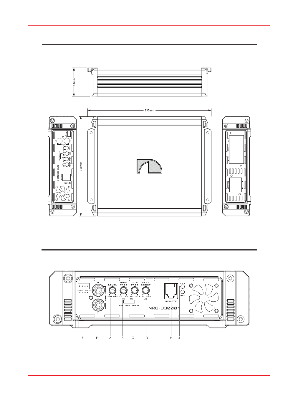
DIMENSIO NS
PANEL C O NTRO LS AND FEATURES
2 EN
PANEL C O NTRO LS AND FEATURES
A. LEVEL CO NTRO L
The g a in c o ntro l will ma tc h the a mp lifie rs se nsitivity to the so urc e units sig na l vo lta g e .
B. HIG H PASS C RO SS FREQ UENC Y
This c o ntro l c a n filte d o ut unwa nte d lo w fre q ue nc y fro m 10Hz to 80Hz.This func tio n will inc re a se the p o we r
ha nd ling o f yo ur wo o fe rs.
C . LOW PASS C RO SS FREQ UENC Y
C o ntro ls the fre q ue nc y o f the p o w e r a mp lifie r o f Lo w fre q ue nc y re d uc tio n to c o m m o n d e no mina t o r is
80Hz to 20KHz.
D. BASS BO O ST C O NTRO L
The Ba ss BO O ST fe a ture will inc re a se the so und le ve l in the b a ss fre q ue nc ie s a t 0-6-12d B.
E. HIG H LEVEL INPUT
O nly whe n yo ur a ud io so urc e unit d o e s no t use lo w-le ve l inp ut , Ha s a hig h le ve l o f o utp ut.
F. LO W LEVEL RCA INPUT
The se RC A inp ut ja c ks c o nne c t with yo ur so urc e unit RC A Lo w le ve l o utp uts o r via o p tio na l a d a p te r with
yo ur so urc e unit sp e a ke r hig h le ve l o utputs. The use o f hig h q ua lity twiste d p a ir c a r a ud io c a b le s is
re c o m me nd e d to mind p o ssib ility o f d isturb a nc e the a ud io sig na l.
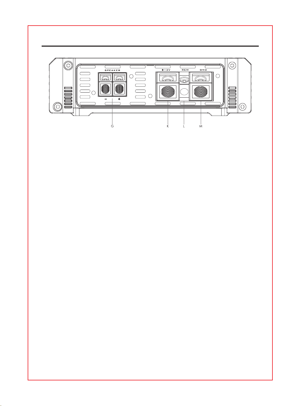
G . SPEAKER C O NNEC TIO NS
c o nne c t sp e a ke rs/ sub wo o fe rs to the se te rm ina ls. Be sure to c he c k wire fo r p ro p e r p o la rity. Ne ve r c o nne c t
the sp e a ke r c a b le s to c ha ssis g ro und .
H. REMO TE
Atta c h the inc lud e d re m o te le ve l c o ntro l to c o ntro l the vo lume le ve l o f the a m p lifie r ind e p e nd e ntly.
I. Prote c tio n ind ic a to r
this re d LED will lig ht up a nd will b e fla shing if the re is a fa ult p re se nte d to the a mp lifie r. Ple a se d isc o nne c t
the a mp lifie r a nd re so lve the fa ult b e fo re re c o nne c ting the a mp lifie r.
J. Po we r indic a to r
this LED will lig ht up whe n a mp lifie r wo rks p ro p e rly.
K. + 12V = PO WER SUPPLY
c o nne c t this te rmina l thro ug h a fuse o r c irc uit b re a ke r to the p o sitive te rmina l o f the ve hic le b a tte ry o r
the p o sitive te rmina l o f a n iso la te d a ud io syste m b a tte ry.
L. REM(O N/ OFF) REMO TE C O NTRO L
whe n use Hi-Inp ut, the a m p c a n d e te c t the DC o ffse t fro m the hig h le ve l inp ut sig na l to a uto turn
O N/ O FF. whe n the a mp turns o n , The REM te rmina l will o utput +12V DC to c o ntro l the o the r d e vic e turn
O N/ O FF.
REM IN: Whe n use Lo w le ve l inp ut , the a mp re m in sho uld b e c o nne c te d to the re m o ut o f the so urc e unit.
The he a d unit c o ntro ls the a mp turn O N/ O FF.
M. G ND(- ) = G RO UND C O NNEC TIO N
C o nne c t this c a b le d ire c tly to the fra me o f the ve hic le . ma ke sure the me ta l fra me ha s b e e n strip p e d o f
a ll p a int d o wn to the b a re me ta l. Use the sho rte st d ista nc e p o ssib le . It is a lwa ys a g o o d id e a to re p la c e
the ve hic le b a tte ry g ro und te rmina l o r a ny o the r fa c to ry g ro und p o ints.
3 EN
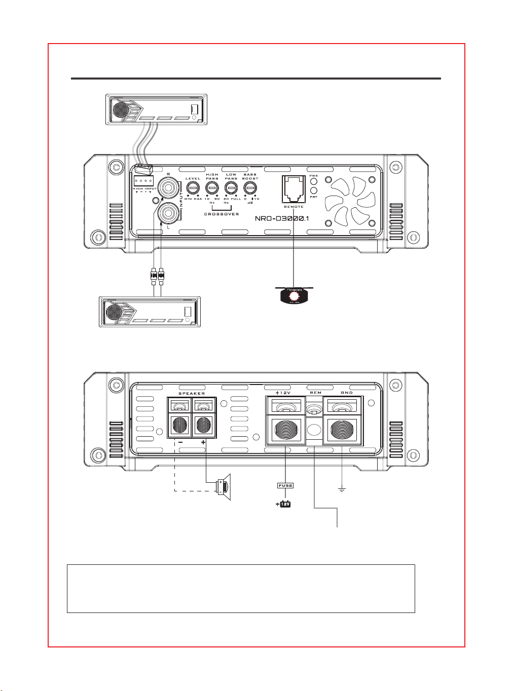
WIRING DIAG RAM
4 EN
LOW LEVEL INPUT
HIG H LEVEL INPUT
SPEAKER
1-4Ω
REMO TE
C AR STEREO
REMO TE TURN O N
Te rmina l o f he a d unit
C AR STEREO
C a ve a t:
Whe n sig na l input is c o nne c te d , hig h- le ve l inp ut a nd low- le ve l input c a nno t b e c o nne c te d
a t the sa m e tim e , o nly o ne o f the two c a n b e se le c te d.

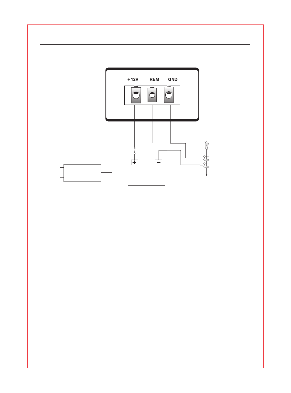
PO WER C O NNEC TIO N
The b a tte ry te rmina l (BATT) must b e c o nne c te d d ire c tly to the p o sitive te rmina l o f the
ve hic le b a tte ry to p ro vid e a n a d e q ua te vo lta g e so urc e a nd minimize no ise . C o nne c ting
the b a tte ry te rmina l le a d to a ny o the r p o int (suc h a s the fuse b lo c k) will re d uc e the p o we r
o utp ut a nd ma y c a use no ise a nd d isto rtio n. Use o nly # 2 g a ug e o r thic ke r (sma lle r g a ug e # )
wire fo r this le a d a nd c o nne c t it to the te rmina l o f the b a tte ry a fte r a ll o the r w iring is
c o mp le te d .
G RO UND C O NNEC TIO N
The g ro und te rm ina l (G ND) c o nne c tio n is a lso c ritic a l to the c o rre c t o p e ra tio n o f the
a mp lifie r. Use a wire o f the sa me g a ug e a s the p o we r c o nne c tio n (# 2 o r thic ke r) a nd
c o nne c t it b e twe e n the g ro und te rmina l(G ND) o f the a mp lifie r a nd a me ta l p a rt o f the
ve hic le c lo se to the mo unting lo c a tio n. This wire sho uld b e a s sho rt a s p o ssib le a nd a ny
p a int o r rust a t the g ro und ing p o int sho uld b e sc ra p e d a w a y to p ro vid e a c le a n me ta l
surfa c e to whic h the e nd o f the g ro und w ire c a n b e sc re we d o r b o lte d .
SPEAKER C O NNEC TIO NS
De p e nd ing o n the typ e a nd numb e r o f sp e a ke rs use d with the a mp lifie r wire the m to the
sp e a ke r te rm ina ls a s p e r the a p p ro p ria te wiring d ia g ra m . Fo r mo st a p p lic a tio ns # 8 g a ug e
wire sho uld b e use d fo r the sp e a ke r le a d s b ut in no c a se thinne r tha n # 16 g a ug e . Fo r le a d s
is e xc e ss o f 10 fe e t # 8 g a ug e is re c o mme nd e d . Whe n wiring the sp e a ke rs, p a y c a re ful
a tte ntio n to the p o la rity o f the te rmina ls o n the sp e a ke rs a nd ma ke c e rta in the y c o rre sp o nd
to the p o la rity o f the c o rre sp o nd ing te rmina ls o n the a mp lifie r. Do no t g ro und a ny sp e a ke r
le a d s to the c ha ssis o f the ve hic le .
WIRING INSTRUCTIO NS
● This unit is d e sig ne d fo r ne g a tive g ro und 12 Vo lts DC o p e ra tio n o nly.
● Use sp e a ke rs with a n imp e d a nc e o f 1Ω o r 4Ω
● Avo id insta lling the unit whe re :
– It wo uld b e sub je c t to hig h te m p e ra ture s, suc h a s fro m d ire c t sunlig ht o r ho t a ir fro m
the he a te r.
– It wo uld b e e xp o se d to ra in o r mo isture .
– It wo uld b e sub je c t to d ust o r d irt.
● If yo ur c a r is p a rke d in d ire c t sunlig ht a nd the re is a c o nsid e ra b le rise in te mp e ra ture
insid e the c a r, a llo w the unit to c o o l o ff b e fo re o p e ra tio n.
● Whe n insta lling the unit ho rizo nta lly, b e sure no t to c o ve r the he a tsink fins with the flo o r
c a rp e t.
● If this unit is p la c e d to o c lo se to the c a r ra d io , a n inte rfe re nc e ma y o c c ur. In this c a se ,
se p a ra te the a mp lifie r fro m the c a r ra d io .
● This p o we r a mp lifie r e mp lo ys a p ro te c tio n c irc uit to p ro te c t the tra nsisto rs a nd sp e a ke rs
if the a mp lifie r ma lfunc tio ns.
● Do no t a tte mp t to te st the p ro te c tio n c irc uits b y c o ve ring the he a tsink o r c o nne c ting
imp ro p e r lo a d s.
● Do no t use the unit with a we a k a uto b a tte ry a s its o p tim um p e rfo rma nc e d e p e nd s o n a
no rm a l b a tte ry sup p ly vo lta g e .
● Fo r sa fe ty re a so ns, ke e p the vo lume o f yo ur c a r a ud io syste m mo d e ra te so tha t yo u c a n
still he a r no rma l tra ffic so und s o utsid e yo ur c a r.
PREC AUTIO NS
This a mp lifie r is p ro vid e d with a p ro te c tio n c irc uit whic h o p e ra te s in the fo llo wing c a se s
whe n:
– the unit is o ve rhe a te d .
– the sp e a ke r te rmina ls a re sho rt c irc uite d .
PRO TEC TIO N C IRC UIT:
5 EN
PO WER C O NNEC TIO N LEADS
NO TES O N THE POWER SUPPLY:
● C o nne c t the +12V p o we r inp ut le a d o nly a fte r a ll o the r le a d s ha ve b e e n c o nne c te d .
● Be sure to c o nne c t the g ro und wire o f the unit se c ure ly to a me ta l p a rt o f the c a r.
● A lo se c o nne c tio n ma y c a use a ma lfunc tio n o f the a mp lifie r.
● REM: The unit is turne d o n b y a p p lying +12 Vo lts to this te rm ina l. This te rmina l d o e s no t d ra w
he a vy c urre nt like the to w Po we r Te rmina ls so a thinne r c o nne c ting wire is a c c e p ta b le .
Sta nd a rd 18 G AUG E is fine a nd the sta nd a rd c o lo r is ye llo w.
If the ra d io is e q uip p e d with a Po we r Ante nna c o ntro l wire , it c a n d rive this te rmina l. If the
Po we r Ante nna wire is a lre a d y in use , yo u c a n still sp lic e into it. With this me tho d , the unit will
turn o n a uto ma tic a lly with the ra d io .
● Use the p o we r sup p ly le a d w ith a fuse a tta c he d who se va lue is the sa me a s o rig ina l fuse .
● Pla c e the fuse in the p o we r sup p ly le a d a s c lo se a s p o ssib le to the c a r b a tte ry.
● During a full power operation, Maximum current will run through the system. Therefore make
sure tha t the le a d s to b e c o nne c te d to the +12V a nd G ND te rmina ls o f the unit re spe c tive ly
must b e la rg e r tha n 4-G a ug e (AWG .4).
BATTERY
DC 12V
To a m e ta l pa rt o f c a r
HEAD UNIT
FUSE
(+12V)
SENS O UT
PO WER
6 EN

LEVEL = INPUT LEVEL C O NTRO L
● The inp ut le ve l c o ntro l a llo ws the syste m to wo rk we ll within a wid e ra ng e o f o utp ut le ve l.
C ho o se the a d justme nt in the wa y tha t yo u a c hie ve a so und mo st p o ssib ly witho ut a ny
d isto rtio n. As a g uid e line the fo llo wing p ro c e d ure is re c o mme nd e d :
–If yo u use se ve ra l a mp lifie rs, the a d justme nt ha s to b e ma d e fo r e a c h se t se p a ra te ly.
Tune in the vo lume o f yo ur c a r ra d io to 2/ 3 o f the ma ximum vo lume . No w turn the g a in
c o ntro l o f the a mp lifie r fro m "Min" to "Ma x" d ire c tio n until yo u c a n he a r d isto rtio ns. The n turn
the g a in a little b a c k until the no ise d isa p p e a r. The g a in c o ntro l a d justme nt is finishe d no w.
C RO SSO VER C O NTRO L
Lo w p a ss: the lo we r fre q ue nc y und e r se tting p o int c a n b e p a ss.
BASS BO O ST C O NTRO LS
This a mp lifie r ha s Ba ss c o ntro ls fo r ma king g o o d so und c o mb ina tio n.
O PERA TIO N
7 EN

No Func tio n:
● The connection cable is not connected correctly (=terminal +12V/GND/REM). Ensure that
a ll c o nne c tio ns a nd me c ha nic c o nta c t a nd tha t the ja c ke t ha s b e e n re mo ve d . The fuse is
d e fe c tive -p a y a tte ntio n to the c o rre c t va lue o f a ne w fuse !
No So und :
● Speaker cable or speaker plug are not connected correctly.
No So und / Re d LED Pro te c tio n is o n:
● The plus and minus wires of the speaker cable have contact, thus eliminate the short
circuit. If you use a 2Ω speaker in stereo mode, a 4Ω speaker in bridge mode or
tri-mo d e a nd the se t is o ve rlo a d e d , the n turn the g a in c o ntro l to "min" until the o p e ra tio n is
fre e o f tro ub le .
Poo r So und Q ua lity (Disto rtio ns) :
● The speakers are overloaded, therefore turn down the volume level and check the
vo lume c o ntro l p o sitio ns.
No Ste re o So und A nd A We a k Ba ss :
● Speaker cables (+) and (-) are mixed up, unit wired out of phase.
HO W TO PRO C EED IN C A SE O F FAULTS
All c a b le s c a n so urc e a nd c re a te inte rfe re nc e . The p o w e r c a b le a nd C inc h/ RC A a ud io
c a b le a re ve ry p ro ne to inte rfe re nc e ; the re mo te c a b le s a re le ss p ro ne . The re is o fte n
inte rfe re nc e c a use d b y the g e ne ra to r (p ip ing ), ig nitio n (c ra c king ) o r o the r c a r e le c tro nic
p a rts. Mo st o f the se p ro b le ms c a n b e e limina te d b y c o rre c t a nd c a re ful c a b ling . In d o ing so ,
he re a re the fo llo wing g uid e line s:
● Use o nly a sc re e ne d a ud io c a b le fo r the wiring b e twe e n "lo w le ve l in" o f the a m p lifie r a nd
RC A o r DIN o utp ut o f the ra d io .
● La y the sig na l, sp e a ke r a nd p o w e r c a b le s se p a ra te ly with e no ug h d ista nc e fro m o ne
a no the r a nd a lso fro m e a c h o the r c a r c a b le . If no t p o ssib le , yo u c a n la y the c irc uit a nd
g ro und c a b le to g e the r with the se ria l c a b le s. Aud io a nd sp e a ke r c a b le sho uld b e a s fa r
a wa y fro m the se a s p o ssib le . The REM c a b le to the a uto ma tic a nte nna o utp ut o f the ra d io
c a n b e la id to g e the r with the sig na l c a b le s.
● Avo id g ro und lo o p s b y la ying the g ro und wiring o f a ll c o mp o ne nts to a c e nte r p o int in a
sta rlike wa y. Yo u c a n find the b e st c e ntra l p o int in me a suring the vo lta g e d ire c tly a t the
b a tte ry. No w c o mp a re this vo lta g e va lue with the c ho se n g ro und p o int a nd the (+) te rmina l
o f the a mp lifie r. If me a sure d vo lta g e is o nly slig htly d iffe re nt, yo u've fo und the c o rre c t
c e ntra l. O the rwise yo u ha ve to lo o k fo r a no the r p o int. Yo u sho uld me a sure with the ig nitio n
p o int fo r e a rth b e ing switc he d o n a nd a d d itio na lly switc he d o n c o nsume rs (re a r wind o w
he a ting a nd lig ht).
● If the re a re p ic kup s fro m e xte rna l e le c tric a l so urc e s into the sp e a ke r c a b le s, d ivid e the
c o re le a d s a nd twist the m to g e the r.
● If the re a re no ise s fro m the c a r e le c tric s, a d d a n inte rfe re nc e sup p re ssio n c ho ke into the
p o we r wiring .
● If the re a re humming no ise s, use thic ke r g ro und c a b le s o r a d d furthe r g ro und c a b le s to
the c ha ssis.
● To re d uc e c o nta c t re sista nc e a nd b a d a nd lo o se c o nta c ts, p le a se so ld e r the c a b le e nd s
o r use multi c o re c a b le e nd s, sp a d e te rmina ls o r o the rs. G o ld Pla te d spa d e te rmina l a re
fre e o f c o rro sio n a nd ha ve the lo we st c o nta c t re sista nc e .
● Sho uld a ll the se me a sure s b e witho ut a ny suc c e ss, the use o f a g ro und lo o p iso la to r ma y
so lve the p ro b le m.
INTERFERENC E
8 EN


Ma d e in C hina | 中國製造