Installation Instructions
Range
To prevent accidents and damage to the range, you must read all
instructions supplied before installing or using the appliance.
en-US, CA M.-Nr. 11 918 390
PRECAUTIONS TO AVOID POSSIBLE EXPOSURE TO
EXCESSIVE MICROWAVE ENERGY
PRECAUTIONS TO AVOID POSSIBLE EXPOSURE TO EXCESSIVE
MICROWAVE ENERGY
(a) Do not attempt to operate this oven with the door open since
open-door operation can result in harmful exposure to microwave
energy. It is important not to defeat or tamper with the safety
interlocks.
(b) Do not place any object between the oven front face and the
door or allow soil or cleaner residue to accumulate on sealing
surfaces.
(c) Do not operate the oven if it is damaged. It is particularly
important that the oven door close properly and that there is no
damage to the: (1) Door (bent), (2) hinges and latches (broken or
loosened), (3) door seals and sealing surfaces.
(d) The oven should not be adjusted or repaired by anyone except
properly qualified service personnel.
2
IMPORTANT SAFETY INSTRUCTIONS
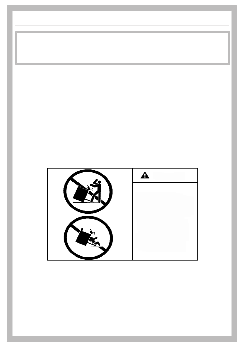
WARNING
Children and adults can tip over the range if has not been secured.
This may lead to fatal injuries.
This range must be secured and connected using the anti-tip
device according to the installation instructions.
If you have moved the range, slide the locking latch onto the anti-
tip device until you feel it lock into place.
Do not use the range if the anti-tip device has not been properly
installed and engaged.
Failure to observe the information contained in the installation
instructions can lead to serious or fatal injuries for children and
adults.
All ranges can tip
Injury to persons
could result
Install anti-tip devices
packed with range
See installation
instructions
WARNING
3
IMPORTANT SAFETY INSTRUCTIONS
WARNING: If the information in this manual is not followed exactly, a fire or
explosion may result causing property damage, personal injury, or death.
- Do not use or store gasoline or other combustible liquids or vapors in the vicinity
of this or any other appliance.
- WHAT TO DO IF YOU SMELL GAS
– Do not try to light any appliance.
– Do not touch any electric switches.
– Do not use any phones inside your building.
– Immediately call your gas supplier from a neighbor's phone. Follow the gas
supplier's instructions.
– If you are unable to reach your gas provider, call the fire department.
- Installation and service must be performed by a qualified installer, qualified
service agency or your gas provider.
(In Massachusetts, installation must be performed by a licensed installer / gas
fitter.)
- Note to the installer:
Please give these installation instructions to the consumer for the local
electrical/gas inspector.
®
®
4

Contents
5
PRECAUTIONS TO AVOID POSSIBLE EXPOSURE TO EXCESSIVE
MICROWAVE ENERGY ...................................................................................... 2
IMPORTANT SAFETY INSTRUCTIONS ............................................................ 3
IMPORTANT SAFETY INSTRUCTIONS ............................................................ 7
Notes on installation ......................................................................................... 16
Data plate ............................................................................................................ 16
Distance to the range hood ................................................................................. 16
Scope of delivery................................................................................................. 16
Toe kick panel and splash guard.................................................................... 16
Installation of the toe-kick .............................................................................. 16
Installation of the drip tray.............................................................................. 16
Optional accessories........................................................................................... 18
RBGAG All Gas Backguard/RBGDF Dual Fuel Backguard ............................ 18
RBS Backsplash............................................................................................. 21
Installation location ............................................................................................. 22
Ventilation....................................................................................................... 22
Range net weight ........................................................................................... 23
Required connections .................................................................................... 23
All Gas Range dimensions................................................................................ 24
HR1124-3AG ..................................................................................................... 24
Detailed views of HR1124-3AG......................................................................... 26
HR1134-3AG, HR1135-3AG, HR1136-3AG .................................................. 30
Detailed views of HR1134-3AG......................................................................... 32
Detailed views of HR1135-3AG......................................................................... 36
Detailed views of HR1136-3AG......................................................................... 40
All Electric Range dimensions ......................................................................... 44
Detailed views of HR1421-3E ........................................................................... 46
Detailed views of HR1622-3i............................................................................. 50
Dual Fuel Range dimensions............................................................................ 54
HR1724-3DF ..................................................................................................... 54
Detailed views of HR1724-3DF ......................................................................... 56
HR1924-3DF ..................................................................................................... 60
Detailed views of HR1924-3DF ......................................................................... 62
HR1934-3DF, HR1935-3DF, HR1936-3DF .................................................... 66
Detailed views of HR1934-3DF ......................................................................... 69
Detailed views of HR1935-3DF ......................................................................... 73
Detailed views of HR1936-3DF ......................................................................... 77

Contents
6
HR1954-3DF, HR1955-3DF, HR1956-3DF .................................................... 81
Detailed views of HR1954-3DF ......................................................................... 84
Detailed views of HR1955-3DF ......................................................................... 88
Detailed views of HR1956-3DF ......................................................................... 92
Anti-tip device.................................................................................................... 96
Before installation................................................................................................ 96
Checking the installation niche ........................................................................... 97
Included accessories........................................................................................... 99
Installation dimensions of locking bolt ................................................................ 99
Installing the Range with the anti-tip device ....................................................... 99
Disconnecting the range from the anti-tip device ............................................... 101
Plumbed water connection .............................................................................. 102
Electrical connection ........................................................................................ 104
Data plate ....................................................................................................... 106
Gas connection.................................................................................................. 107
Burner ratings .................................................................................................... 109
Burner ratings HR1124-3AG ............................................................................. 109
Burner ratings HR1134-3AG ............................................................................. 110
Burner ratings HR1135-3AG ............................................................................. 110
Burner ratings HR1136-3AG ............................................................................. 111
Burner ratings HR1724-3DF.............................................................................. 112
Burner ratings HR1924-3DF.............................................................................. 112
Burner ratings HR1934-3DF.............................................................................. 113
Burner ratings HR1935-3DF.............................................................................. 113
Burner ratings HR1936-3DF.............................................................................. 114
Burner ratings HR1954-3DF.............................................................................. 115
Burner ratings HR1955-3DF.............................................................................. 115
Burner ratings HR1956-3DF.............................................................................. 116
Customer Service.............................................................................................. 117
Contact in the event of a fault ............................................................................. 117
Data plate ............................................................................................................ 117
Appliance warranty and product registration ...................................................... 117
Caring for the environment .............................................................................. 118
Copyrights and licenses ................................................................................... 119
IMPORTANT SAFETY INSTRUCTIONS
When using the appliance, follow basic safety precautions, including the
following:
Read all instructions before installation and use of the range to prevent
accidents and machine damage.
This range complies with current safety requirements. However,
improper use of the appliance can result in personal injury or
damage to property.
Please read the installation instructions carefully before installing
and connecting the appliance.
Read the operating instructions before using the range for the first
time. To prevent accidents and damage to the appliance, always
observe both the installation instructions and operating
instructions. Both documents contain important information about
installation, safety, use and maintenance.
Miele cannot be held liable for damage occurring as a result of
non-compliance with the instructions.
Keep these installation instructions and operating instructions in a
safe place and pass them on to any future owner.
7
IMPORTANT SAFETY INSTRUCTIONS
When using the appliance, follow basic safety precautions, including the
following:
Read all instructions before installation and use of the oven to prevent
accidents and machine damage.
WARNING - To reduce the risk of burns, electric shock, fire, injury to persons,
or exposure to excessive microwave energy:
This appliance complies with current safety requirements.
Improper use of the appliance can lead to personal injury and
material damage.
Read all instructions before installing or using the oven for the first
time. Only use the appliance for its intended purpose.
Keep these operating instructions in a safe place and pass them
on to any future user.
Read and follow the specific “PRECAUTIONS TO AVOID
POSSIBLE EXPOSURE TO EXCESSIVE MICROWAVE ENERGY”
found at the beginning of this manual.
Only use the appliance for its intended purpose. Install or locate
this appliance only in accordance with the provided installation
instructions and all local codes.
Appropriate use
This range is intended for domestic use and use in other similar
environments.
This appliance is not intended for outdoor use.
Use the range exclusively under normal domestic conditions:
- Use the oven for baking, roasting, broiling, defrosting, canning
and drying food.
- Use the cooktop to prepare food and keep it warm.
Any other use is not permitted.
8

IMPORTANT SAFETY INSTRUCTIONS
Risk of Fire! Do not use this oven to store or dry combustible
materials.
Persons who lack physical, sensory or mental abilities, or
experience with the appliance should not use it without supervision
or instruction by a responsible person.
The oven compartment is equipped with special bulbs to cope
with particular conditions (e.g., temperature, moisture, chemical
resistance, abrasion resistance, and vibration). These special bulbs
must only be used for the purpose for which they are intended. They
are not suitable for room lighting.
Safety with children
Children should be supervised in the vicinity of the range. Never
allow children to play with the range.
Children must be kept away from the range unless they are
constantly supervised.
Risk of burns due to improper use. Do not allow children to
operate the range.
Burn Hazard - Do not allow children to use the oven. Failure to do
so can result in severe burns or serious injury.
Burn Hazard - Do not allow children to use the cooktop. Failure to
do so can result in severe burns or serious injury.
Risk of suffocation from packaging material. While playing, children
may become entangled in packaging material (such as plastic
wrapping) or pull it over their head, presenting the risk of suffocation.
Keep packaging material away from children.
Risk of injury caused by hot surfaces. Children’s skin is far more
sensitive to high temperatures than that of adults. External parts of
the oven such as the door glass, control panel, and the vent become
quite hot.
Do not let children touch the oven when it is in operation.
9

IMPORTANT SAFETY INSTRUCTIONS
Risk of injury caused by hot surfaces. Children’s skin is far more
sensitive to high temperatures than that of adults. The oven gets
much hotter during the Self Clean program than during normal use.
Do not let children touch the oven during the Self Clean program.
The cooktop gets hot when in use and remains hot for some time
after being turned off. Keep children away from the appliance until it
has cooled down and is no longer a burn hazard.
Burn hazard!
Keep the spaces above and behind the cooktop clear of any items
that could draw the attention of children. Otherwise, they can be
tempted into climbing onto the appliance.
Risk of burning or scalding.
Turn pot and pan handles inward, so children cannot pull them down
and be burned.
Risk of injury from the open door. The oven door can support a
maximum weight of 33lbs (15kg). Children could injure themselves
on an open door.
Do not let children sit on the door, lean against it, or swing on it.
Technical safety
This appliance must be installed and connected in compliance
with the installation instructions.
Unauthorized installation, maintenance, and repairs can cause
considerable danger for the user. Installation, maintenance, and
repairs should only be carried out by a Miele authorized technician.
Do not carry or lift the range by the oven door handle or the
control panel!
Check whether the anti-tip device is properly installed and locked
into place (see“Anti-tip device”):
- The anti-tip device must be fastened to the floor or wall with
suitable screws.
- You must be able to feel that the locking latch is engaged in the
bolt of the anti-tip device.
10

IMPORTANT SAFETY INSTRUCTIONS
Temporary or permanent operation on an autonomous power
supply system or a power supply system that is not synchronized
with the grid power supply (e.g., island networks, back-up systems)
is possible. A prerequisite for operation is that the power supply
system complies with the specifications of EN50160 or an
equivalent standard.
The function and operation of the protective measures provided in
the domestic electrical installation and in this Miele product must
also be maintained in isolated operation or in operation that is not
synchronized with the grid power supply, or these measures must be
replaced by equivalent measures in the installation. As described, for
example, in the current version of VDE-AR-E 2510-2.
Slide the range's locking latch into place on the anti-tip device.
The locking latch must be noticeably engaged with the bolt of the
anti-tip bracket.
A damaged range can be dangerous. Always check for visible
signs of damage. Never use a damaged appliance.
The electrical safety of the range can only be guaranteed when it
is properly grounded. Compliance with this essential safety
requirement is absolutely mandatory. If in any doubt, please have the
building's wiring system inspected by a qualified electrician.
Proper installation: Make sure that your appliance has been
installed correctly and that it has been grounded by a qualified
technician.
To avoid damaging the range, make sure that the connection data
(voltage and frequency) on the data plate correspond to the
building's power supply before connecting the appliance.
When in doubt, consult a qualified electrician.
Installation and maintenance of the gas connection must be
performed by qualified installers, service agencies or gas providers.
11

IMPORTANT SAFETY INSTRUCTIONS
During installation, maintenance and repair work, e.g. if the oven
lighting is broken, the range must be completely disconnected from the
power supply (see “Frequently asked questions”). The gas inlet valve
must be closed. It is only completely isolated from the supply when:
- The circuit breakers have been switched off, or
- the fuses of the electrical installation have been completely
removed, or
- the plug (if present) is removed from the outlet. To do this, pull the
plug not the cord.
- Shut off the gas supply and disconnect the range from the gas
supply. Installation and maintenance of the gas connection must
be performed by qualified installers, service agencies or gas
providers.
Do not use a power strip or extension cord to connect the range
to electricity. These are a fire hazard and do not guarantee the
required level of appliance safety.
This range must not be installed and operated in non-stationary
installations (e.g., on a ship).
Risk of injury due to electric shock. Any contact with live
connections or tampering with the electrical or mechanical
components of the range will endanger your safety and may lead to
appliance malfunctions.
Do not open the range housing under any circumstances.
Any repairs not performed by a Miele authorized service
technician will void the warranty.
Miele can only guarantee the safety of the appliance when original
Miele parts are used. Faulty components must only be replaced with
genuine Miele parts.
The range requires a sufficient supply of cool air for efficient
operation. Make sure that the supply of cool air is not hindered in
any way (e.g., by installing heat insulation strips in the cabinet niche).
In addition, the required supply of cool air must not be excessively
heated by other heat sources.
12

IMPORTANT SAFETY INSTRUCTIONS
Changes or modifications not expressly approved by Miele may
void the user's authority to operate the oven.
Danger of electric shock.
If the cooktop is defective, immediately turn the appliance off and
discontinue use. Disconnect it from the electricity and gas supply.
Contact Customer Service.
Risk of electric shock! If the ceramic surface of the cooktop is
defective or chipped, cracked or broken in any way, immediately
switch the cooktop off and do not continue to use it. Disconnect the
range from the power supply and contact Miele Technical Service.
Reaching over a hot cooktop to access the cabinets can result in
burns. You can reduce the risk of burns by installing a range hood
that extends at least 4 3/4" (12 cm) past the bottom of the cabinets.
For safety reasons, only use the range when it has been fully installed.
The water shut-off valves must be accessible when the appliance
is installed.
The protective sleeve of the water intake hose must not be
damaged or become kinked.
The integrated water protection system offers protection from
water damage, provided the following conditions are met:
- The appliance is properly installed (electric and water).
- A damaged appliance is dangerous. Contact Miele to have it
repaired immediately.
- Turn off the water supply when the appliance is not in use for an
extended period (e.g., vacation).
The water quality must conform to the requirements for drinking
water in the country in which the oven is being used.
Cleaning and care
Do not clean the non-slip mat from the Gourmet Warming Drawer
in the dishwasher or washing machine. Never place it in the oven to
dry!
13

IMPORTANT SAFETY INSTRUCTIONS
Only clean parts listed in these operating and installation
instructions.
There is a delicate fiberglass seal around front of the oven
compartment provide a seal for the glass on the inside of the oven
door. This can be damaged by rubbing or scouring. If possible,
refrain from cleaning this.
Do not use oven cleaners. Do not use standard oven cleaners in
the oven compartment or on the front of the oven. Never line the
oven with oven liners.
Risk of injury due to electric shock. The steam from a steam
cleaning appliance could reach live electrical components and cause
a short circuit. Never use a steam cleaner for cleaning.
Scratches on the door glass can cause the glass to break. Do not
use abrasive cleaners, hard sponges, brushes, or sharp metal tools
to clean the door glass.
Try to prevent the interior walls being splashed with food
containing salt. If this does happen, wipe it away thoroughly to avoid
corrosion to stainless steel surfaces inside the oven compartment.
The side runners can be removed (see “Cleaning and care of the
oven – Removing the side runners”). Reinstall the side runners correctly.
Coarse soiling in the oven compartment can cause thick smoke to
develop. Remove coarse soiling from the oven compartment before
running the Self Clean program.
In warm, moist environments, there is a higher probability of pest
infestations. Ensure the oven and the area surrounding it are always
kept clean.
Damage caused by pests is not covered by the warranty.
The cooktop is installed above a Self Clean oven. Do not use it
during self cleaning, as this could trigger the overheating protection
on the cooktop (see “Safety features of the induction cooktop”,
“Overheating protection”).
14

IMPORTANT SAFETY INSTRUCTIONS
The following applies to stainless steel surfaces:
Adhesives will damage the coated stainless steel surface and
cause it to lose its dirt-repellent protective coating. Do not use sticky
notes, adhesive tape, or other types of adhesive on the stainless
steel surface.
Magnets can cause scratches. Do not use the stainless steel
surface as a magnetic notice board.
Accessories
Only use original Miele accessories. Using parts or accessories
from other manufacturers will invalidate the warranty, and Miele
cannot accept liability.
Only use the Miele probe supplied with the appliance. If it is faulty,
it must be replaced with a new original Miele probe.
The plastic on the probe can melt at very high temperatures. Do
not use the probe when using the broiling operating modes. Do not
store the probe in the oven compartment when it is not being used.
Accessories that are not suitable for the Self Clean program will
be damaged by the high temperatures. Remove all accessories that
are not suitable for the Self Clean program from the oven
compartment before starting the Self Clean process. This also
applies to optional accessories that are not suitable for the Self
Clean program (see “Cleaning and care of the oven”).
Preparing for a long period of absence
If you turn off your domestic water connection when you’re going
to be away for a long period of time, please note that this may not be
enough to prevent water damage. To eliminate the risk of water
damage, close the faucet at each individual appliance.
KEEP THE OPERATING AND INSTALLATION INSTRUCTIONS IN A SAFE
PLACE AND REVIEW THEM PERIODICALLY.
15
Notes on installation
*INSTALLATION*
16
The models described in these
operating instructions can be found at
the end.
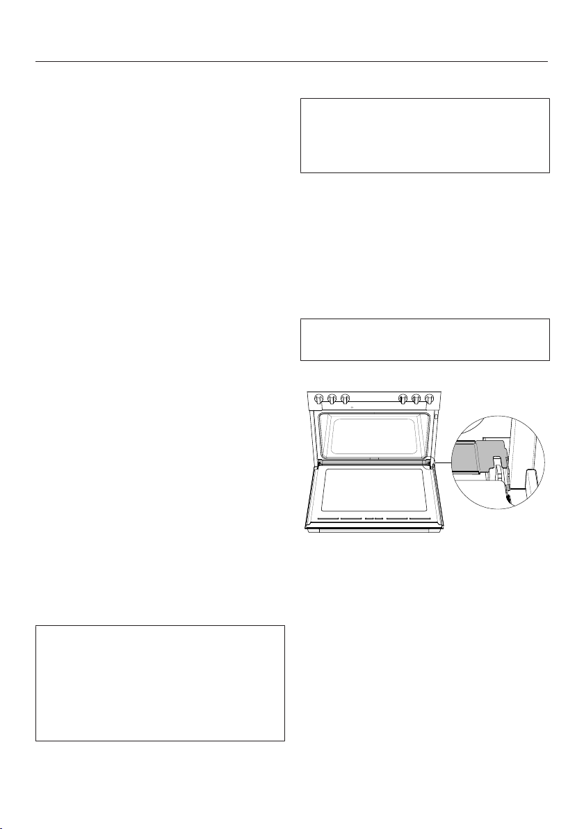
Data plate
The data plate is located behind the toe
kick panel. The toe kick panel is
attached to the toe kick of the Range by
magnets so it can be removed and put
back again easily.
There you can find the model number,
serial number and the connection data
(voltage/frequency/maximum rated
load) for your Range.
Have this information available if you
need to contact Miele so that any
issues can be rectified as quickly as
possible.
Distance to the range hood
The minimum clearance between the
appliance and a range hood above will
be listed by the hood manufacturer.
If there is more than one appliance
installed below the range hood, each
with a different safety clearance, the
largest clearance must be used.
Scope of delivery
Toe kick panel and splash guard
30" and 36" Range
These components are located in the
packaging of the Range.
48" Range
These components are pre-
assembled.
Installation of the toe-kick
The toe-kick has sheet metal lugs and
magnets by means of which it can be
positioned and attached to the base of
the range.
Position the toe-kick in such a way
that the sheet metal lugs are facing
the provided holes in the base.
Push the toe-kick onto the base of
the range until it audibly locks into
place.
Installation of the drip tray
The drip tray covers the gap between
the oven cavity and the door.
Open the oven door.
Lay the drip tray over the gap
between the oven cavity and the
door.
Close the oven door.
Notes on installation
*INSTALLATION*
17
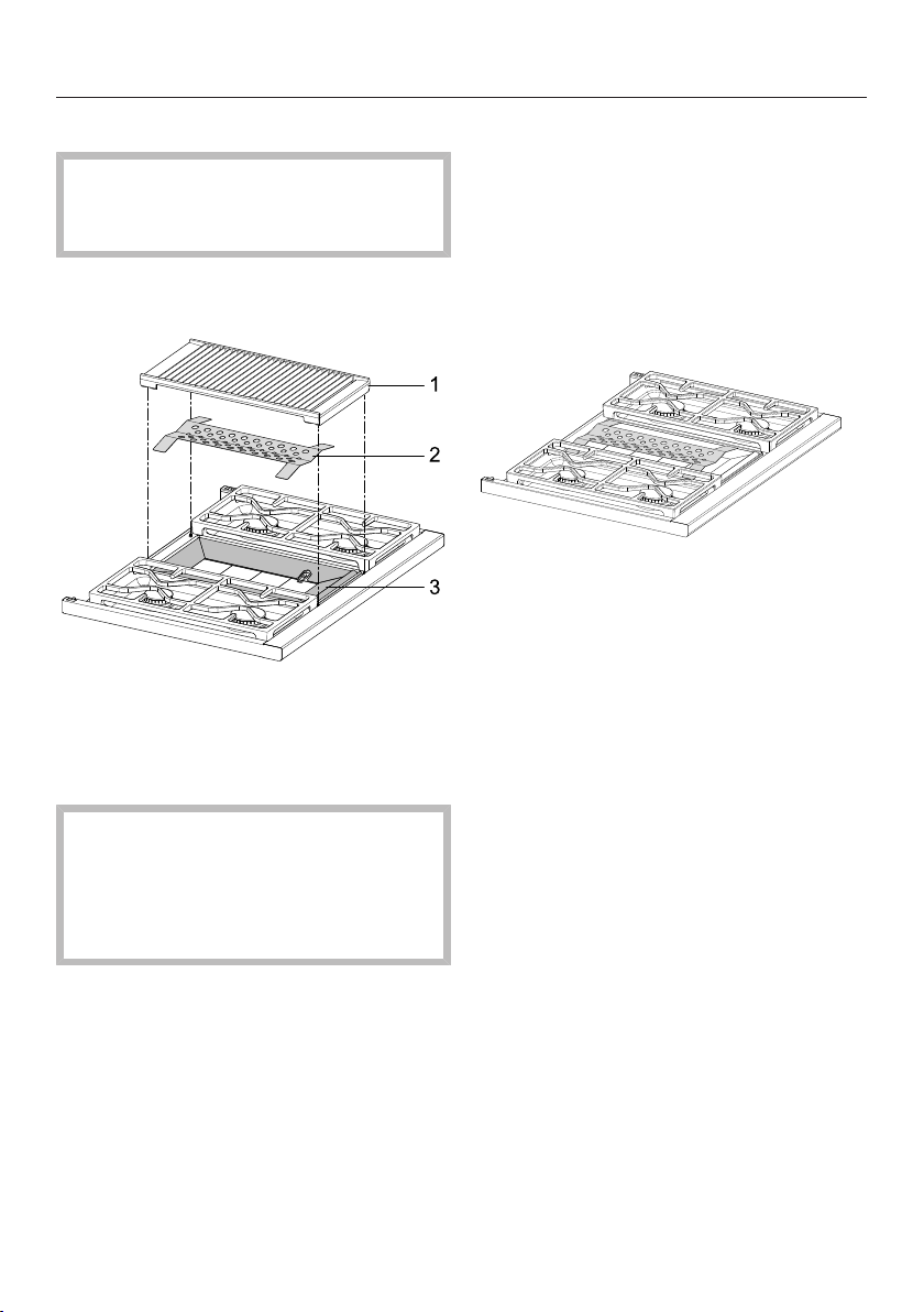
Disassembling the grill
Danger of burning!
Burners must be switched off. Make
sure the cooktop has cooled down.
To make cleaning easier, you can
dismantle the grill.
a
Grill
b
Protective panel
c
Frame
Risk of injury!
The cast-iron grill is heavy.
Carry the grill carefully and place it
securely on a soft surface so that it
lies flat.
Remove the grill from the cooktop.
Remove the protective panel and,
if required, the frame .
Clean the parts with warm water,
liquid dish soap, and a soft sponge.
Dry all parts with a soft cloth.
Reinstall by following these instructions
in reverse order.
Place the frame on the surface
burner. The recess for the igniter is
located on the right side in the lower
quarter of the frame.
Place the protective panel on the
frame .
Replace the grill .

Notes on installation
*INSTALLATION*
18
Optional accessories
All accessories listed in these
instructions are designed to be used
with the Miele Range.
These can be ordered from www.miele-
shop.com, Miele Customer Service, or
from your Miele dealer.
When ordering, please quote the model
number of your Range and the
reference number of the accessories
required.
RBGAG All Gas Backguard/RBGDF
Dual Fuel Backguard
Depending on the model, you can
exchange the existing island trim of
your appliance for a larger range
backguard. The backguard is available
in the following heights: 12“ (305 mm)
and 20” (508 mm).
All Gas Range
Risk of injury caused by hot vapors.
Hot vapors are emitted above the
island trim during Self Clean as well
as when cooking food in the oven.
You could burn yourself on the hot
vapors.
Do not reach above the island trim
and keep others away from it when
you are using the oven.
All Gas Range
Hot vapors are emitted above the
island trim during Self Clean as well
as when cooking food in the oven.
The emission of vapors can soil and
discolor surfaces above the island
trim.
Take precautions to protect sensitive
surfaces such as marble, granite,
and tiles against soiling and
discoloration (surfaces of this nature
can be difficult or even impossible to
clean).
Notes on installation
*INSTALLATION*
19
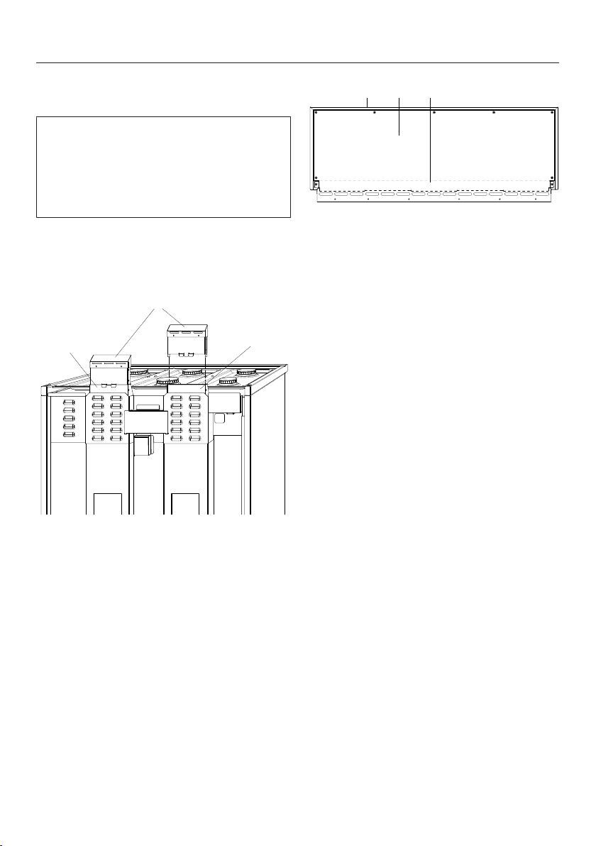
Mounting the RBGAG All Gas
Backguard
The rear of the Range must be
accessible.
Mount the backguard before installing
the anti-tip device and connecting the
Range.
Undo the screws from the island trim.
Pull back the island trim slightly until
it can be removed.
1
22
a
Extender
b
Air duct
Insert one extender onto each of
the left and right air ducts .
Screw the extenders into place
with 2 screws each.
1 2 3
a
Backguard
b
Rear backguard panel
c
Interior panel
To avoid scratching the backguard
, place it front side downward on a
soft surface (e.g., a blanket). The
lower edge should line up with the
edge of the table so that the
backguard is lying flat.
Remove the screws from the rear of
the backguard.
Remove the rear and interior
panels.
Notes on installation
*INSTALLATION*
20
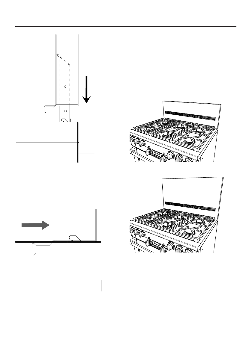
1
2
a
Backguard
b
Range
Push the backguard over the air
duct extenders from above.
As soon as the backguard is sitting
on the Range, push the backguard
backward.
Secure the interior panel and the rear
panel to the backguard with the
screws supplied.
Secure the backguard to the Range
with the screws supplied.
Backguard 12" (305mm)
Backguard 20" (508mm)

Notes on installation
*INSTALLATION*
21
Mounting the Dual Fuel RBGDF
Backguard
The rear of the Range must be
accessible.
Mount the backguard before installing
the anti-tip device and connecting the
Range.
Undo the screws from the island trim.
Pull back the island trim slightly until
it can be removed.
Reinstall the backguard by following
these instructions in reverse order.
RBS Backsplash
The backsplash is intended for
installation to a Miele Range Hood (DAR
model). Observe the installation
instructions of the Miele Range Hood.
Notes on installation
*INSTALLATION*
Installation location
This Range is not intended for outdoor use.
Ranges with a plumbed water connection must not be installed in rooms where
there is a risk of freezing temperatures.
The floor of the space where the appliance is to be installed must be flat, level, and
made of a strong, rigid material.
The niche floor must be made of strong, rigid material.
Because the Range is heavy and has to be secured with the anti-tip device
supplied, the surface must be able to fully bear the load of the appliance. If
necessary, seek the advice of an architect or construction expert.
Do not carry or lift the range by the oven door handle or the control panel!
Ventilation
The air intake and outlet openings must not be covered or blocked in any way.
22
Notes on installation
*INSTALLATION*
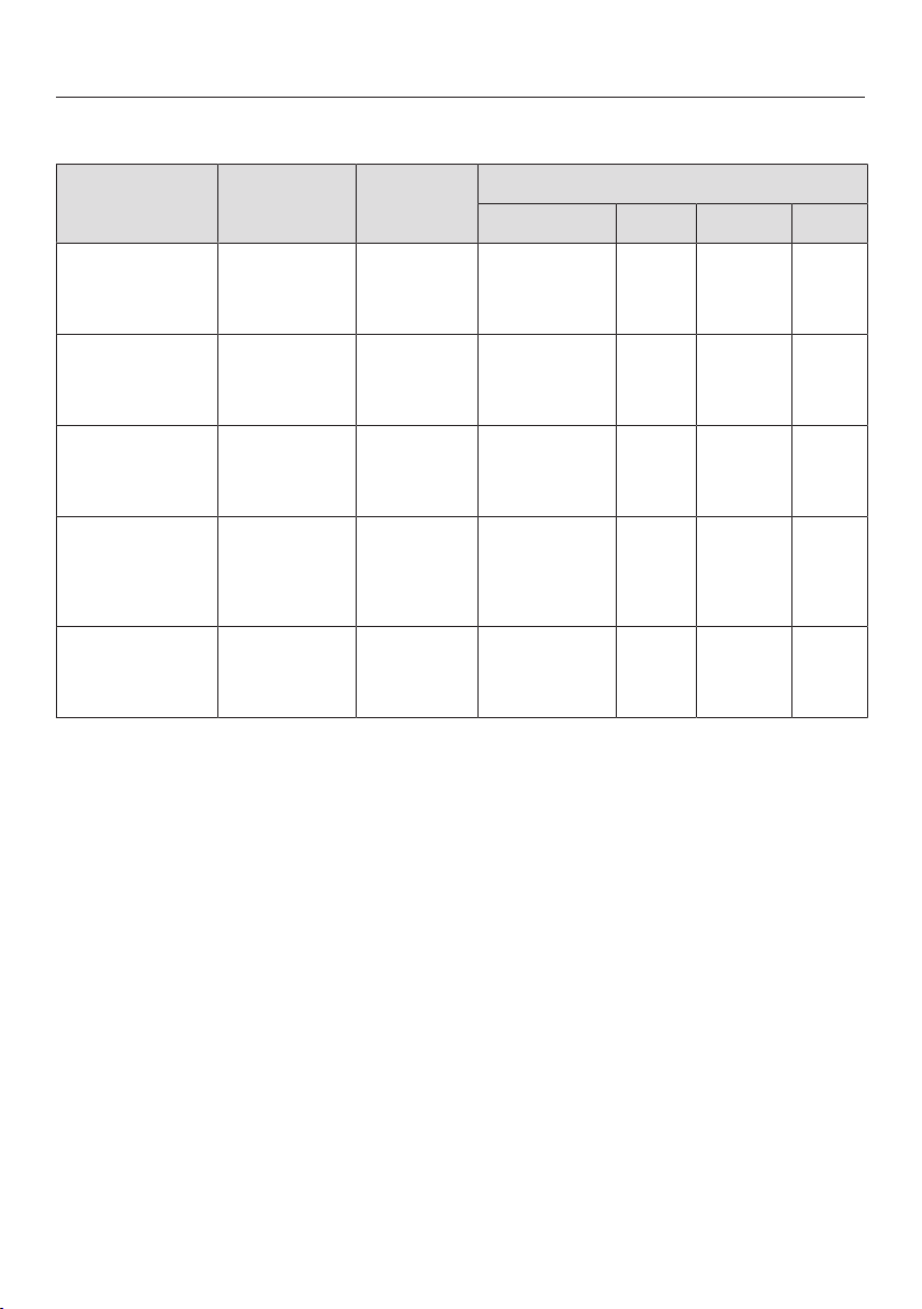
Range net weight
The Range is heavy.
Due to the size and weight of the appliance, installation should be performed by
two people.
Model Width Net weight incl.
accessories
HR112x-3AG
HR1421-3E*
HR1622-3i
HR1724-3DF
HR192x-3DF
2915/16"
(762mm)
approx.307lbs(140kg)
HR113x-3AG
HR193x-3DF
3515/16"
(915mm)
approx.405lbs(180kg)
HR195x-3DF 4715/16"
(1,220mm)
approx.573lbs(260kg)
Required connections
Model Electrical
connection
Gas connection Plumbed water
connection
HR112x-3AG
HR113x-3AG
Yes Yes No
HR1421-3E* Yes No No
HR1622-3i Yes No Yes
HR172x-3DF Yes Yes No
HR192x-3DF
HR193x-3DF
HR195x-3DF
Yes Yes Yes
* Only available in Canada.
23

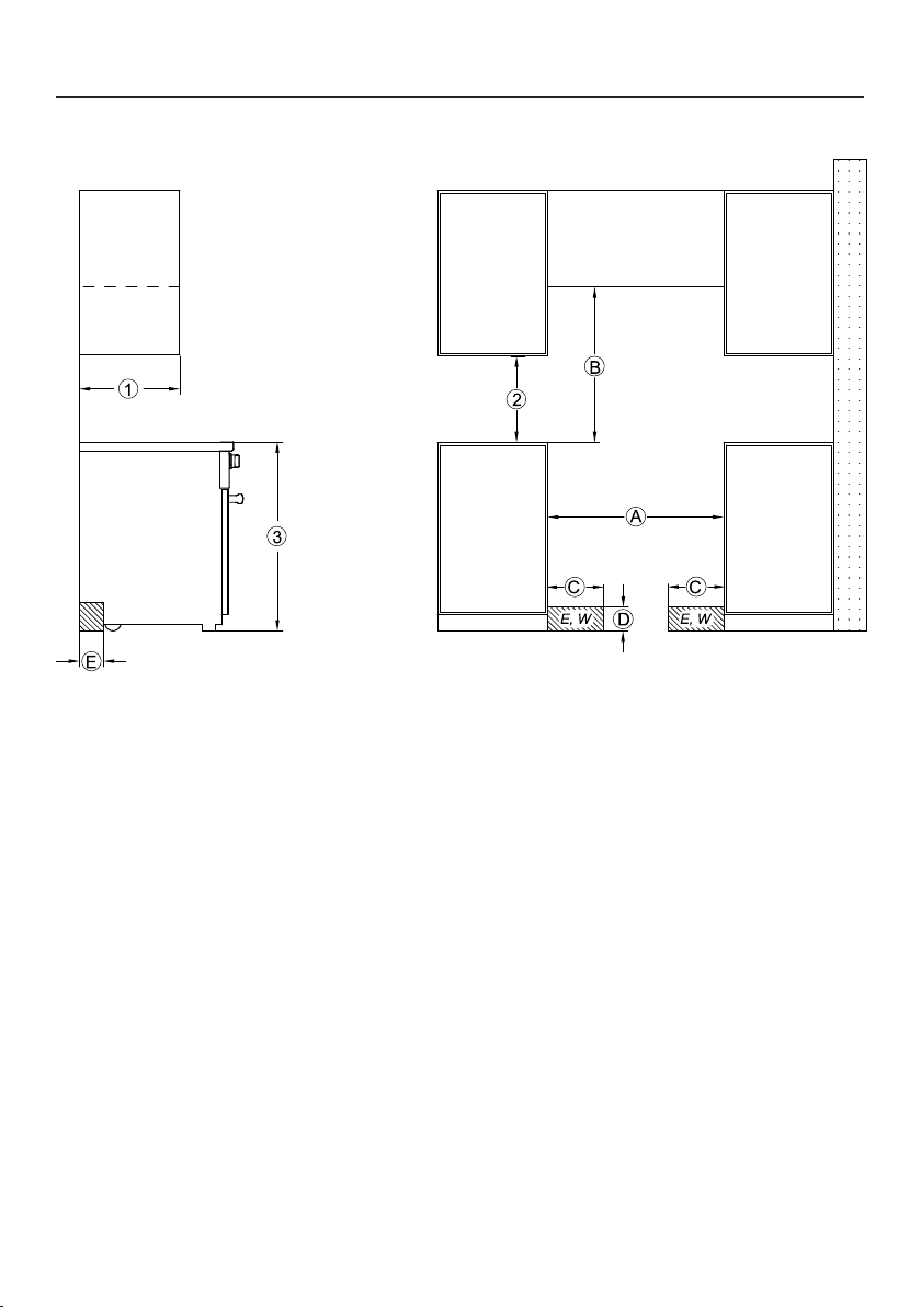
All Gas Range dimensions
*INSTALLATION*
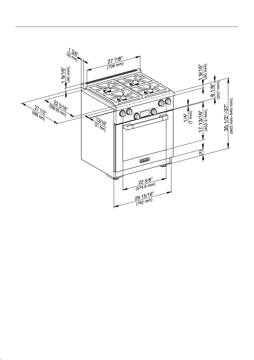
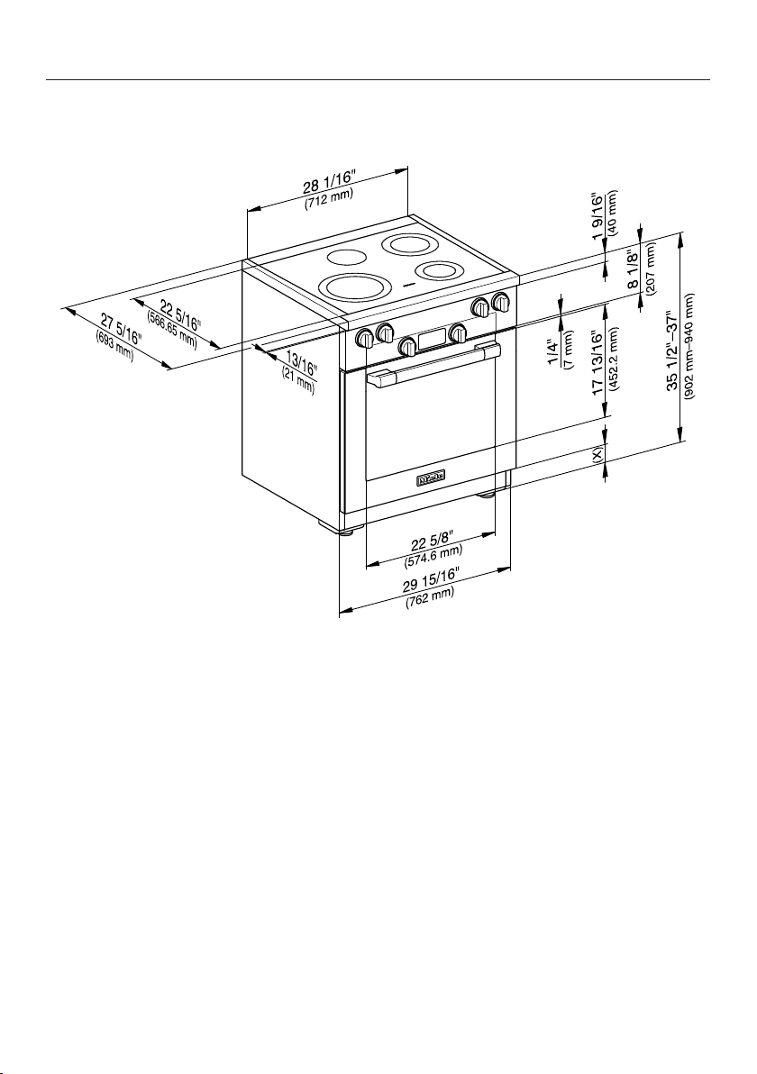
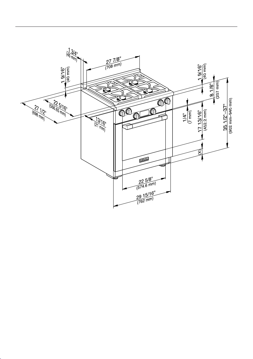
HR1124-3AG
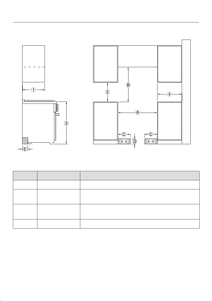
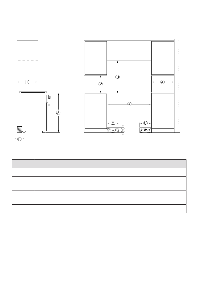
, , The shaded area represents the installation area for the connections:
E = Electrical connection, G = Gas connection
No. Dimensions Description
13" (330mm) Maximum depth of upper cabinet
18" (457mm) Minimum safety distance to bottom edge of upper
cabinet
35 1/2"–37"
(901–940mm)
Distance from the floor to cooktop surface
10" (254mm) Minimum safety distance to combustible surfaces.
24
All Gas Range dimensions
*INSTALLATION*
No. Dimensions Description
min. 30"
(762mm)
Niche width
Please contact Miele Customer Service for more
information.
37" (940mm) Minimum safety distance between the top of the
cooktop surface and the bottom of an unprotected
combustible surface.
30" (762mm) Minimum safety distance between the top of the
cooktop surface and the bottom of the Miele
Ventilation Hood (DAR model with DRxBXL or
DRxBXXL blower).
Refer to the installation instructions for the Miele Ventilation Hood,
“Appliance dimensions” (Distance between cooktop and ventilation
hood (S)).
For all other ventilation hoods please consult the manufacturer’s
specifications for required distances.
approx. 101/16"
(256mm)
Maximum connection width right
and left
Position of
the wall
socket
approx. 41/2"
(115mm)
Maximum connection height
approx. 213/16"
(72mm)
Maximum connection depth
Please observe a minimum safety distance of at least 12" (305mm) from combustible
surfaces located behind the appliance. For zero clearance installation the Miele Backguards
will satisfy the required minimum safety distance to combustible surfaces. The Miele
Backguard is available in 12"(305mm) or 20"(508mm) heights.
25

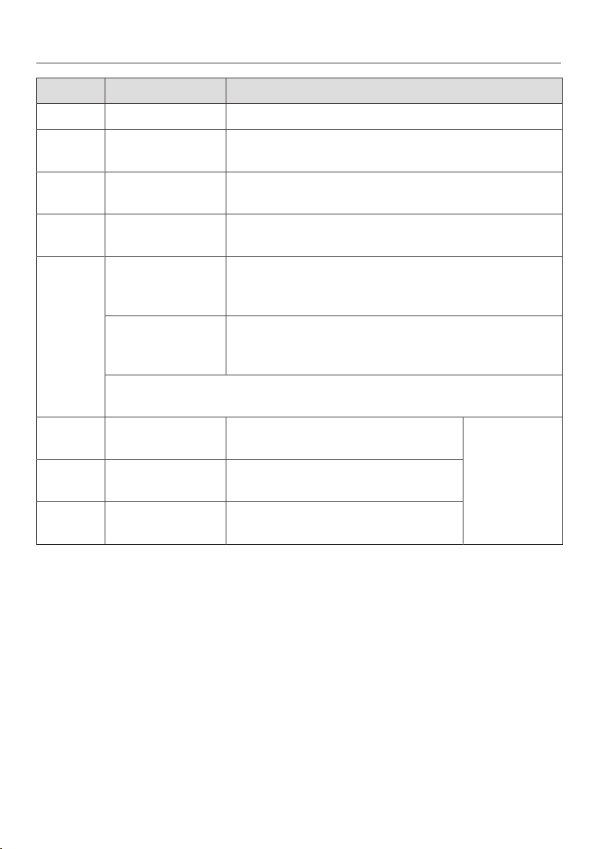
All Gas Range dimensions
*INSTALLATION*
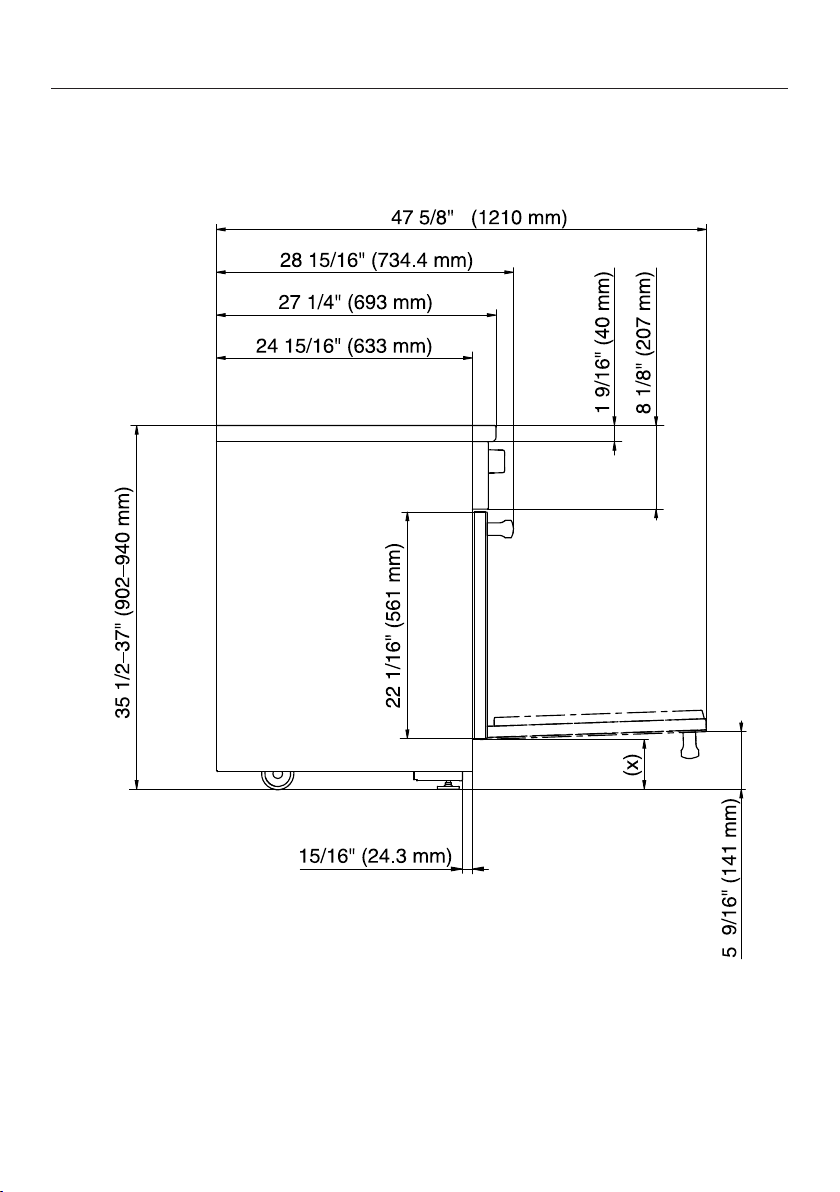
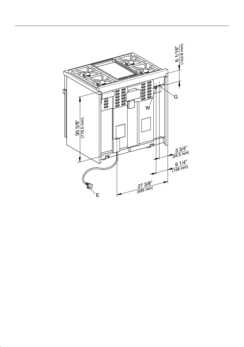
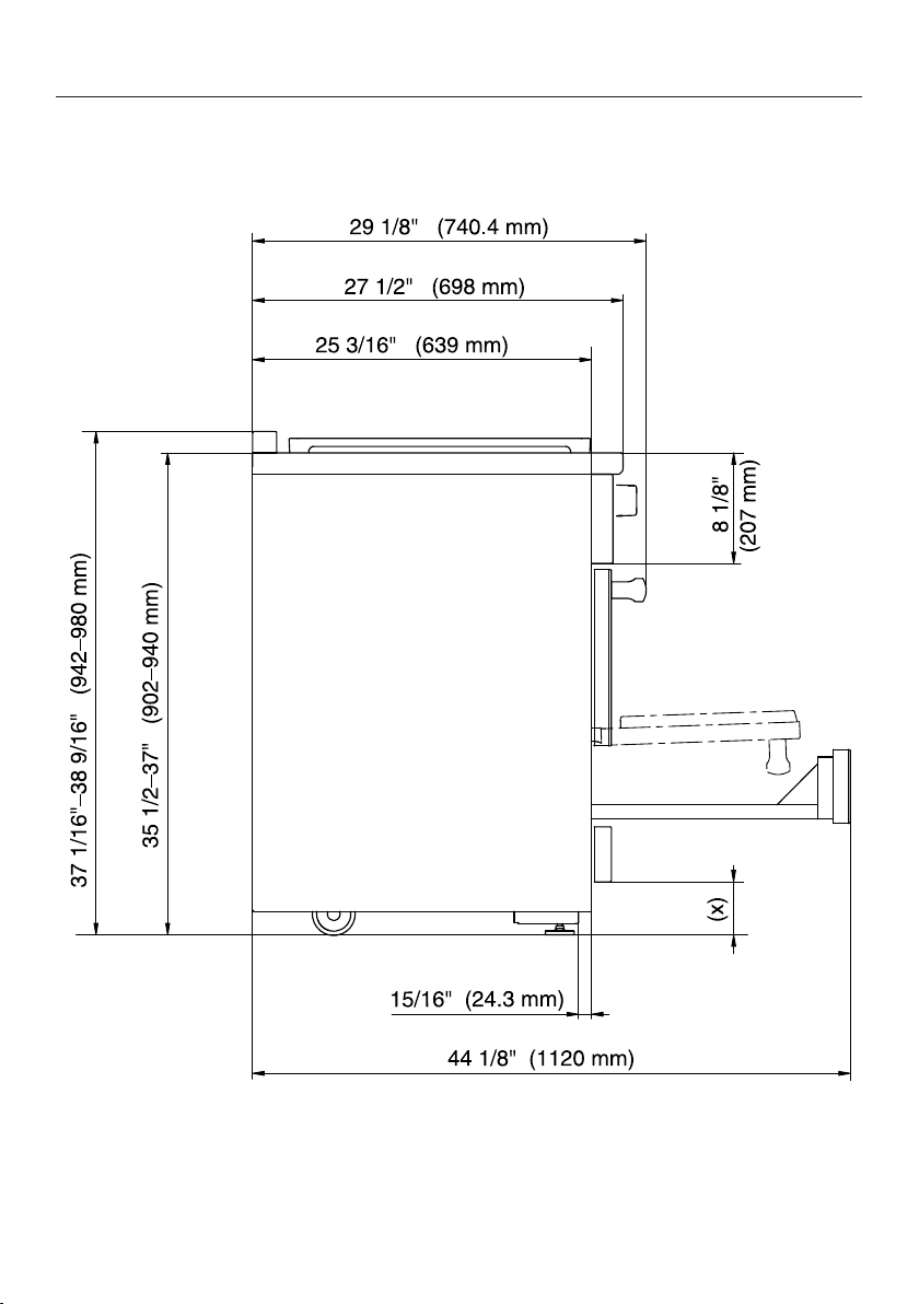
Detailed views of HR1124-3AG
Side view of HR1124-3AG
(x) = Depending on the appliance height adjustment: 5"–6 1/2"
(127mm–165.1mm)
26

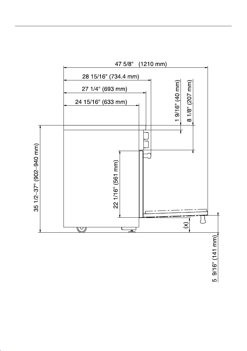
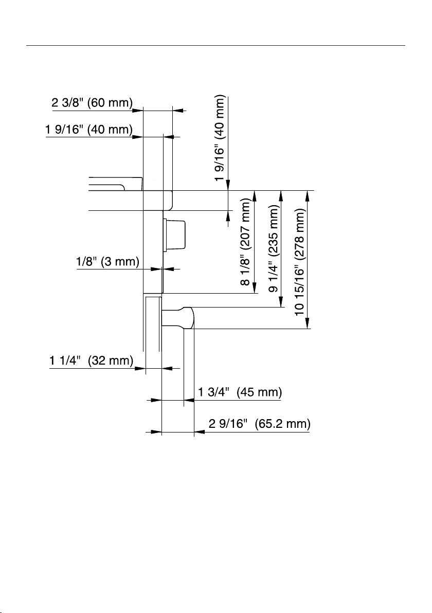
All Gas Range dimensions
*INSTALLATION*
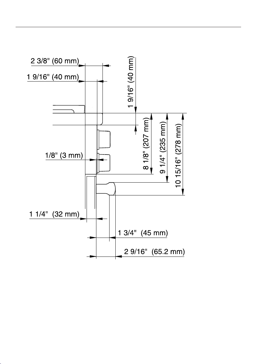
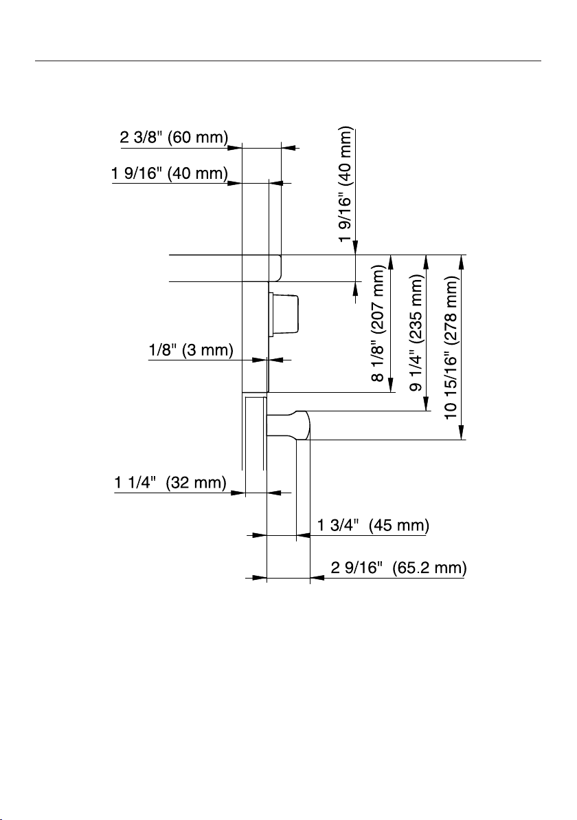
Detailed front side view of HR1124-3AG
27
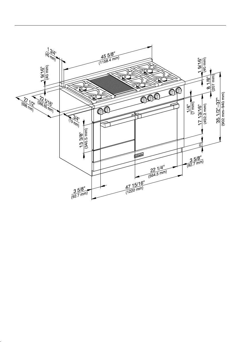
All Gas Range dimensions
*INSTALLATION*
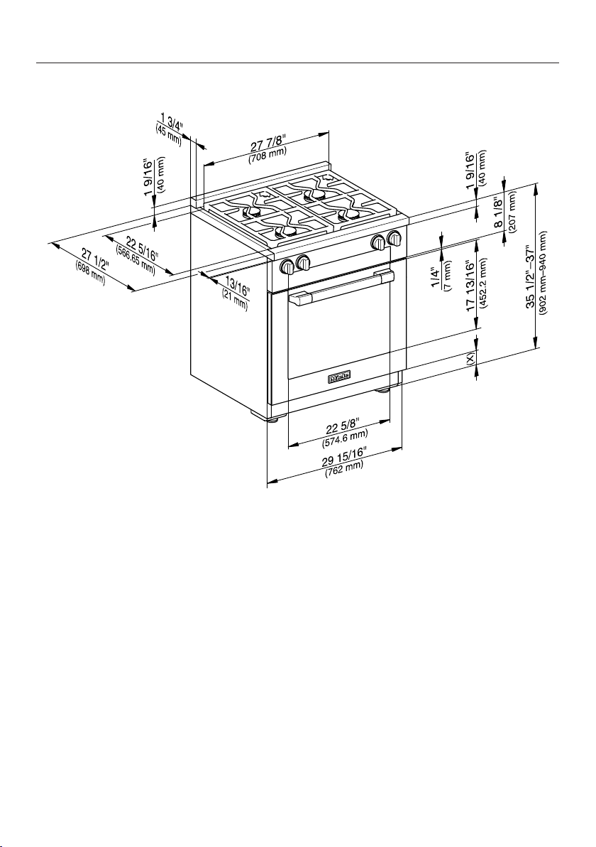
Front view of HR1124-3AG
(x) = Depending on the appliance height adjustment: 5"–6 1/2"
(127mm–165.1mm)
28
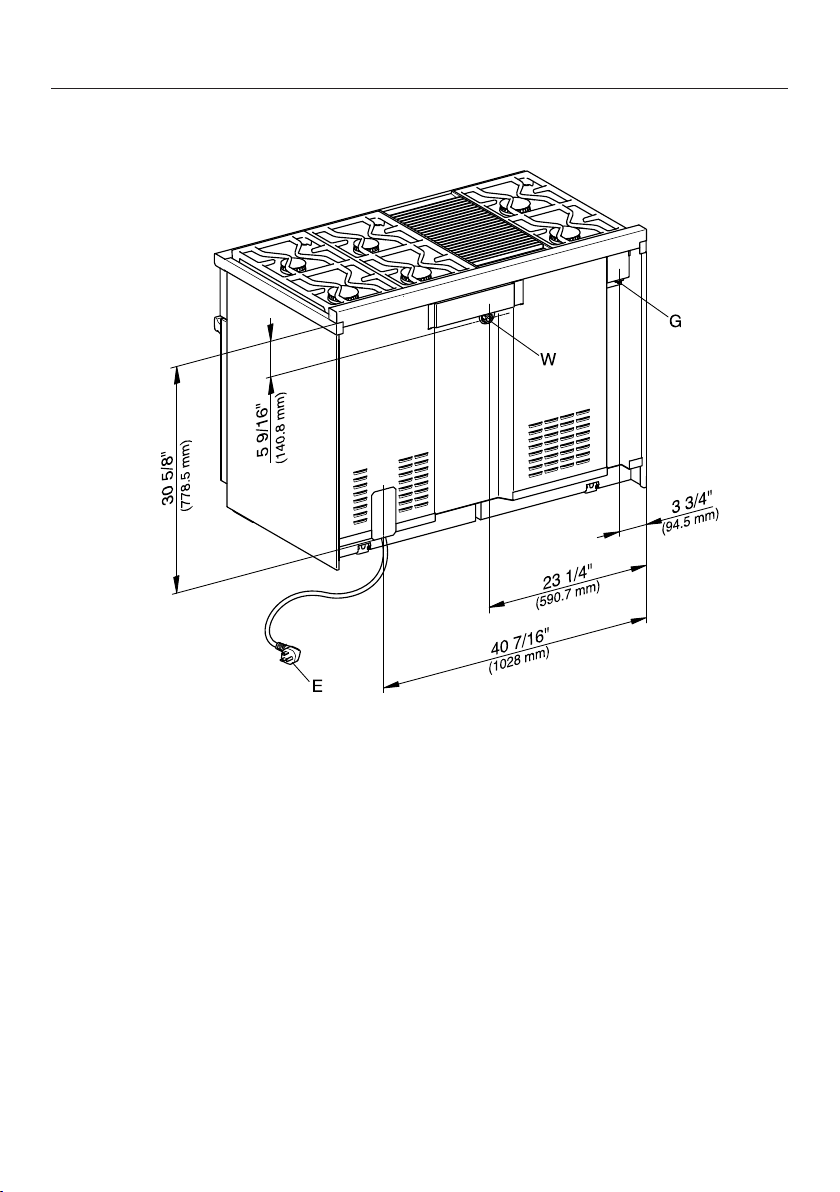
All Gas Range dimensions
*INSTALLATION*
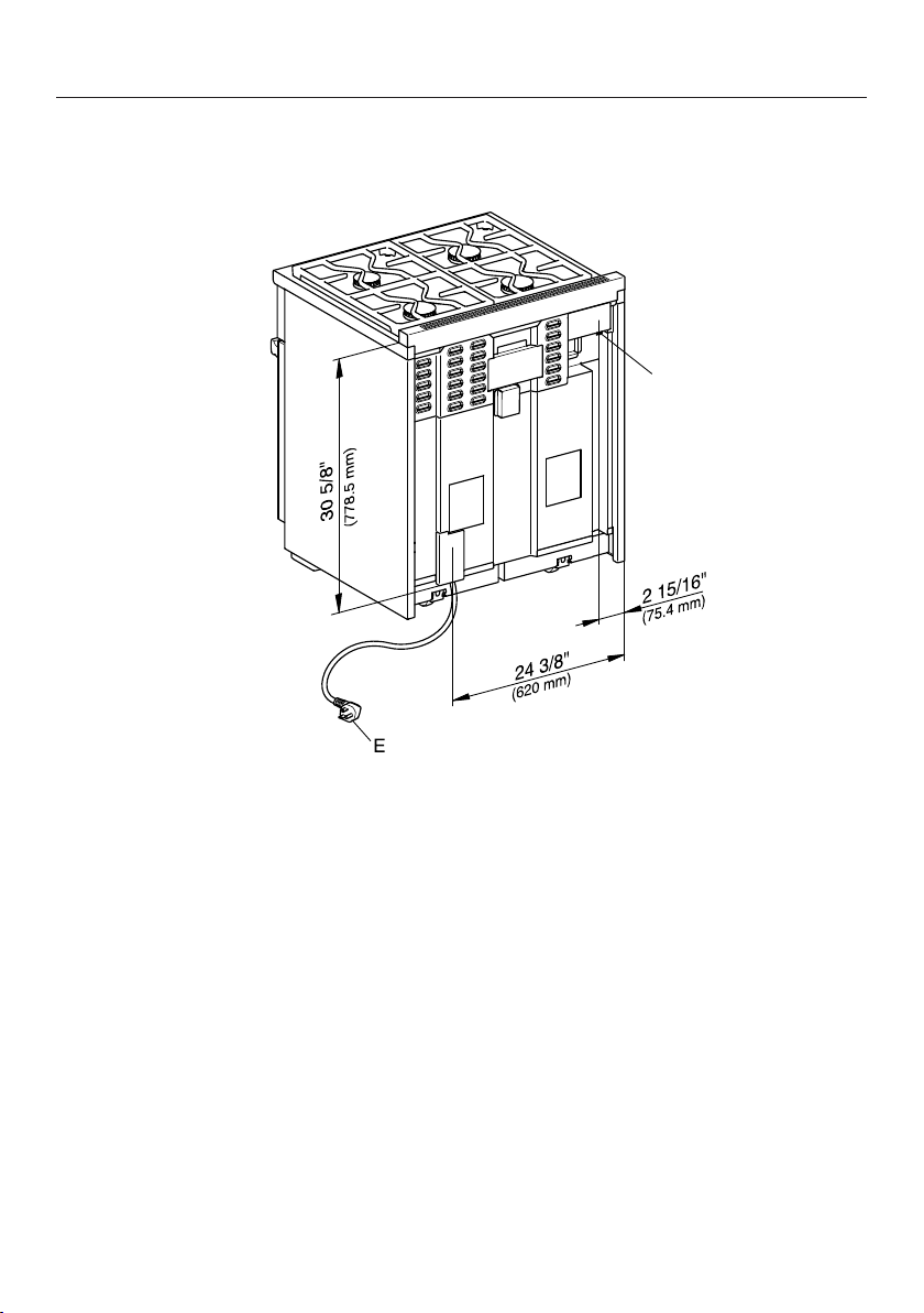
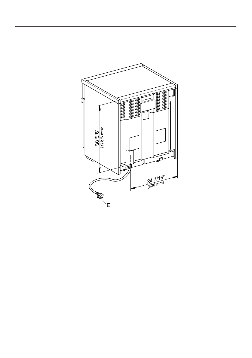
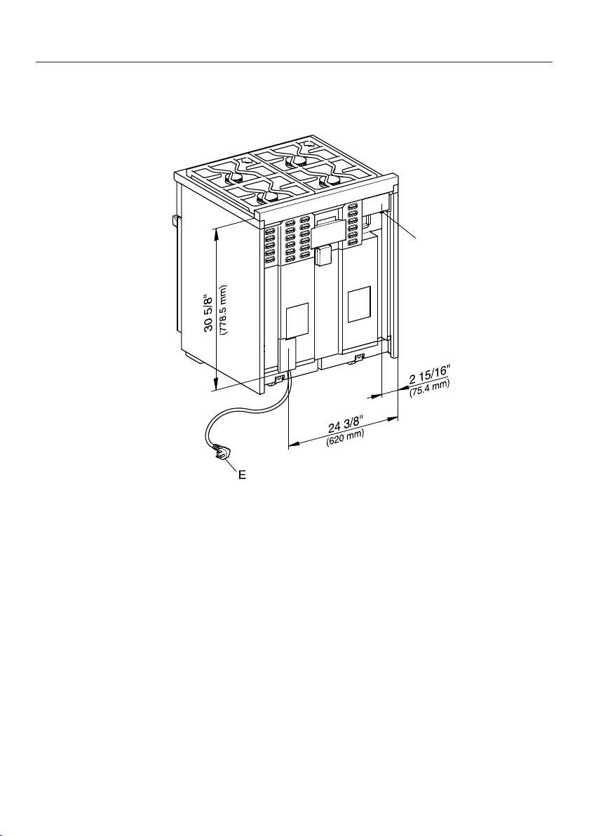
Rear view of HR1124-3AG
G
E = Electrical connection
G = Gas connection
29
All Gas Range dimensions
*INSTALLATION*
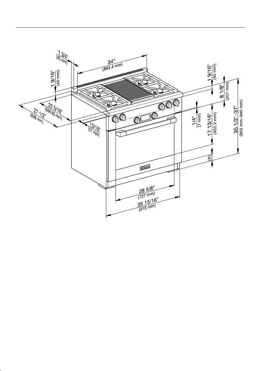
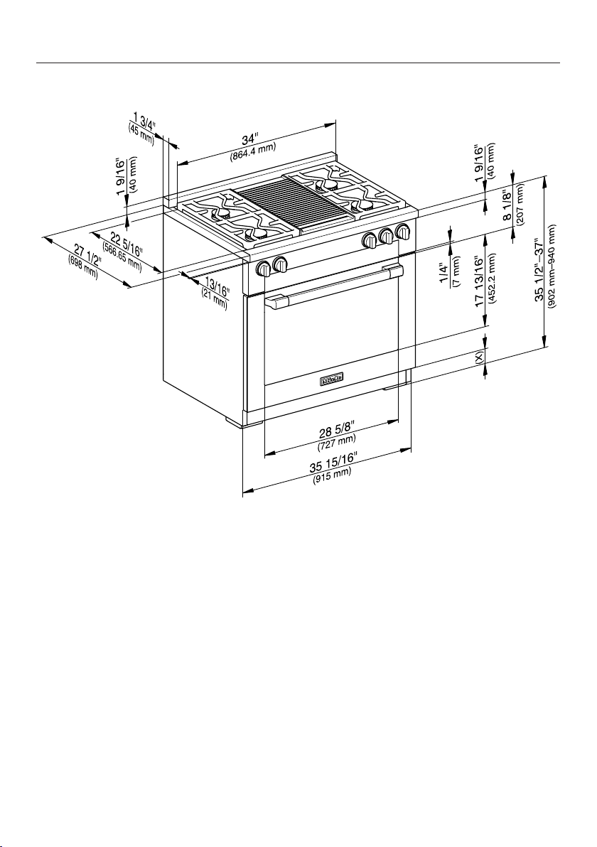
HR1134-3AG, HR1135-3AG, HR1136-3AG
, , The shaded area represents the installation area for the connections:
E = Electrical connection, G = Gas connection
No. Dimensions Description
13" (330mm) Maximum depth of upper cabinet
18" (457mm) Minimum safety distance to bottom edge of upper
cabinet
35 1/2"–37"
(901–940mm)
Distance from the floor to cooktop surface
10" (254mm) Minimum safety distance to combustible surfaces.
30

All Gas Range dimensions
*INSTALLATION*
No. Dimensions Description
min. 36"
(915mm)
Niche width
Please contact Miele Customer Service for more
information.
37" (940mm) Minimum safety distance between the top of the
cooktop surface and the bottom of an unprotected
combustible surface.
30" (762mm) Minimum safety distance between the top of the
cooktop surface and the bottom of the Miele
Ventilation Hood (DAR model with DRxBXL or
DRxBXXL blower).
Refer to the installation instructions for the Miele Ventilation Hood,
“Appliance dimensions” (Distance between cooktop and ventilation
hood (S)).
For all other ventilation hoods please consult the manufacturer’s
specifications for required distances.
approx. 131/16"
(332.5mm)
Maximum connection width right
and left
Position of
the wall
socket
approx. 41/2"
(115mm)
Maximum connection height
approx. 213/16"
(72mm)
Maximum connection depth
Please observe a minimum safety distance of at least 12" (305mm) from combustible
surfaces located behind the appliance. For zero clearance installation the Miele Backguards
will satisfy the required minimum safety distance to combustible surfaces. The Miele
Backguard is available in 12"(305mm) or 20"(508mm) heights.
31

All Gas Range dimensions
*INSTALLATION*
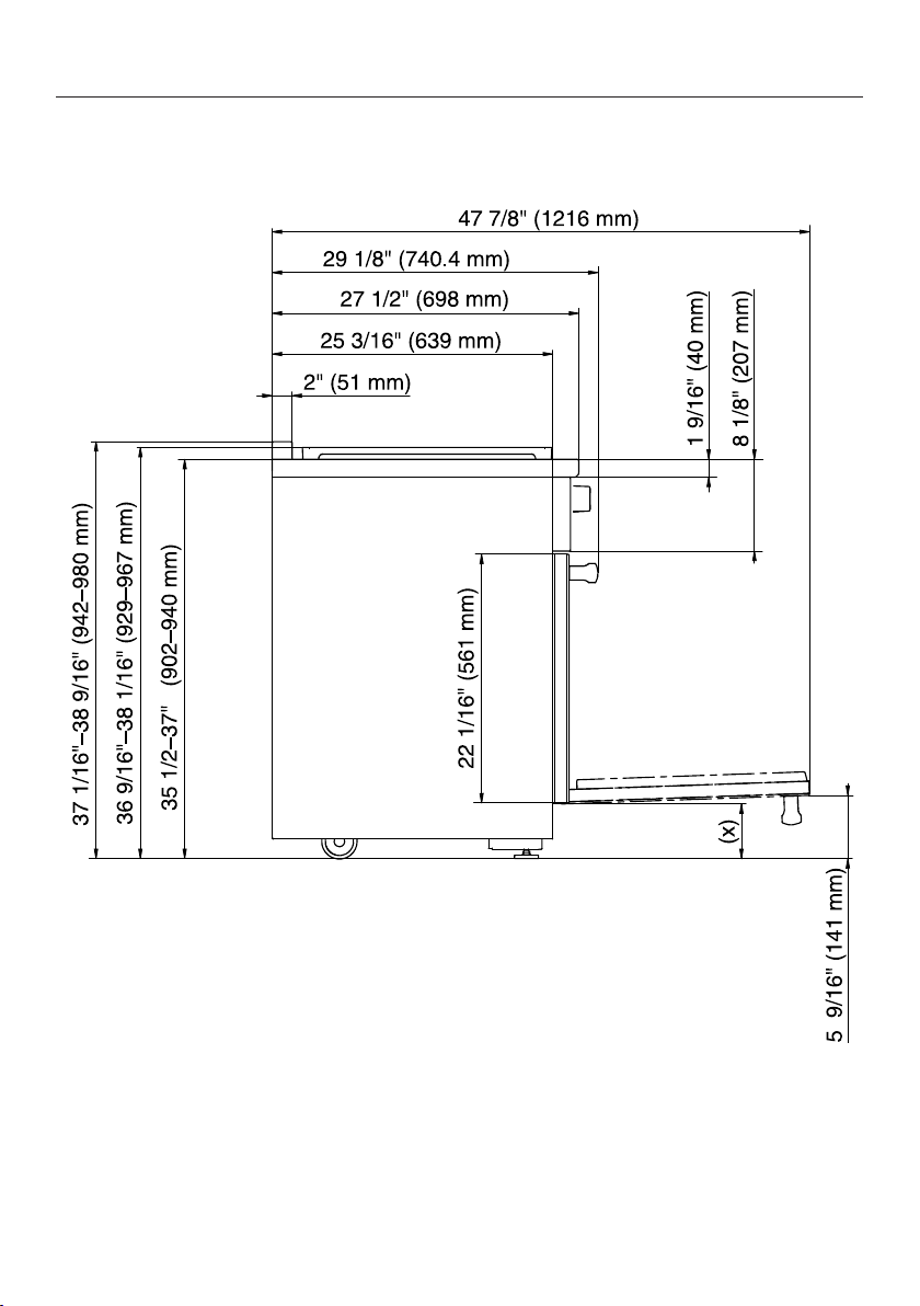
Detailed views of HR1134-3AG
Side view of HR1134-3AG
(x) = Depending on the appliance height adjustment: 5"–61/2"
(127mm–165.1mm)
32

All Gas Range dimensions
*INSTALLATION*
Detailed front side view of HR1134-3AG
33

All Gas Range dimensions
*INSTALLATION*
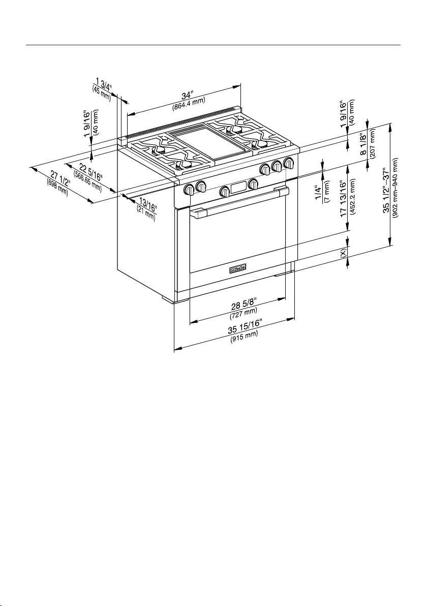
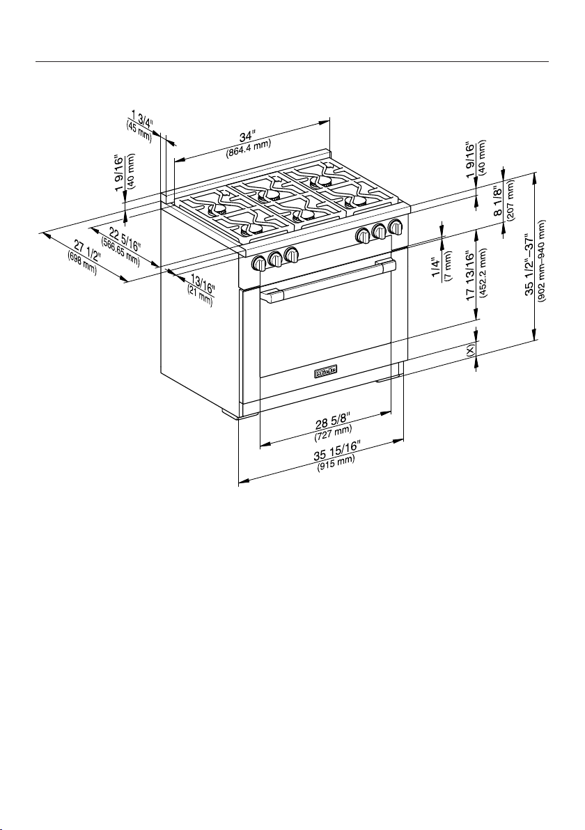
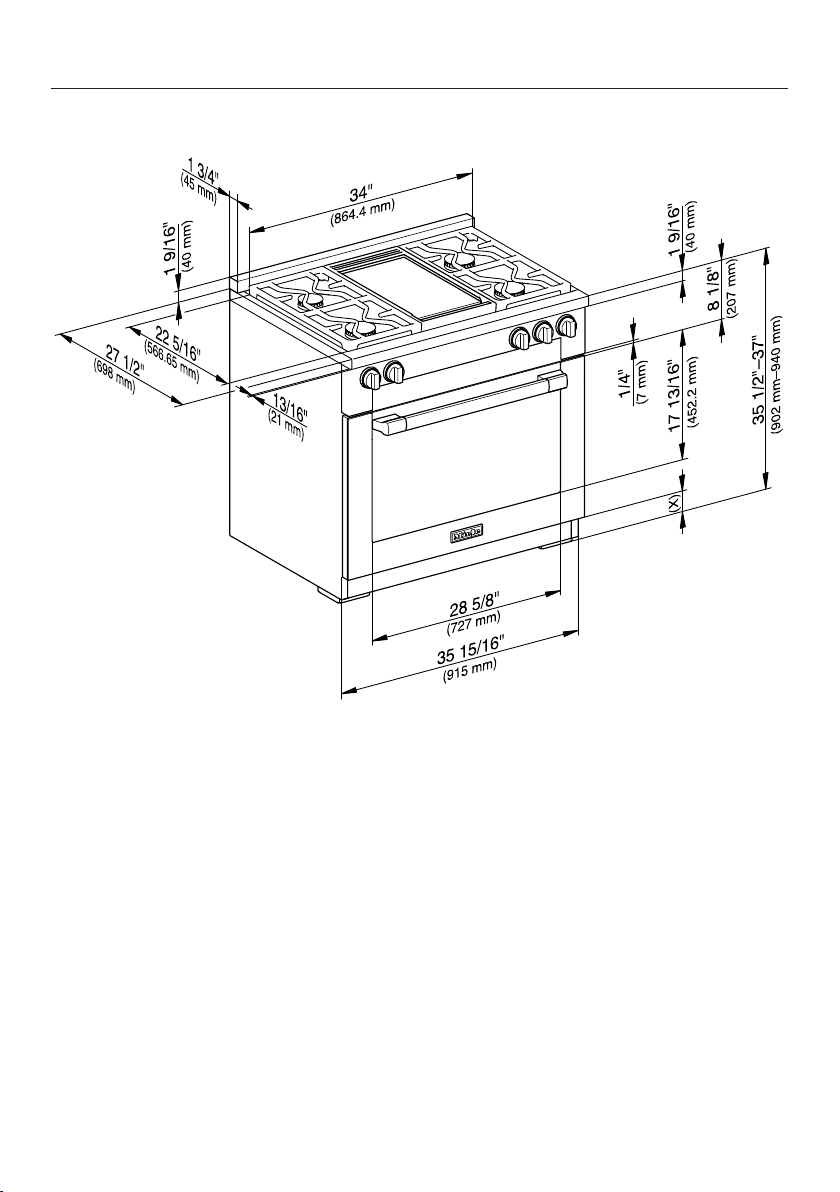
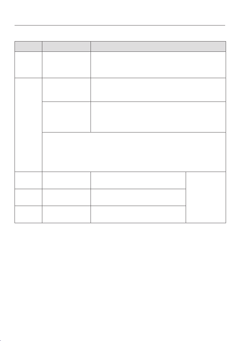
Front view of HR1134-3AG
(x) = Depending on the appliance height adjustment: 5"–61/2"
(127mm–165.1mm)
34
All Gas Range dimensions
*INSTALLATION*
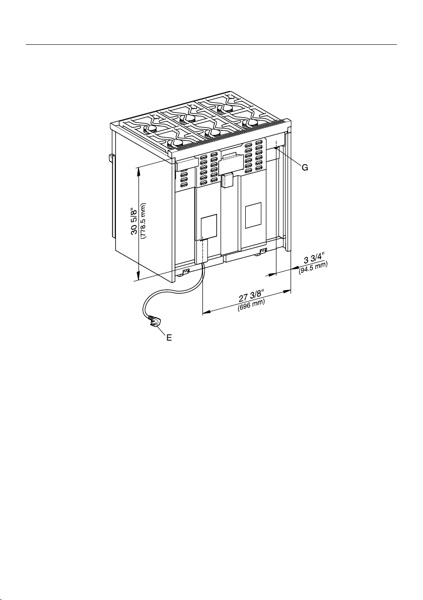
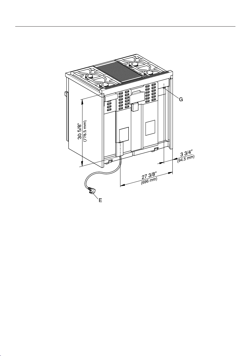
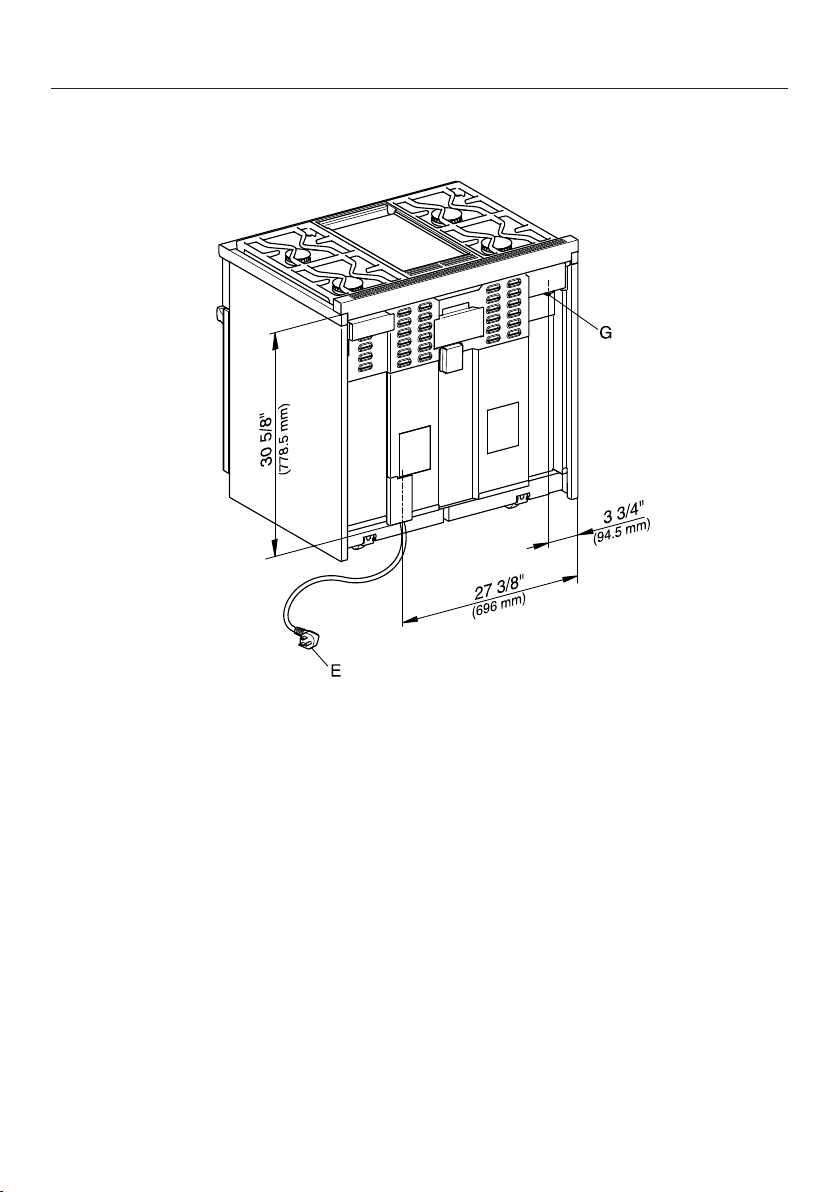
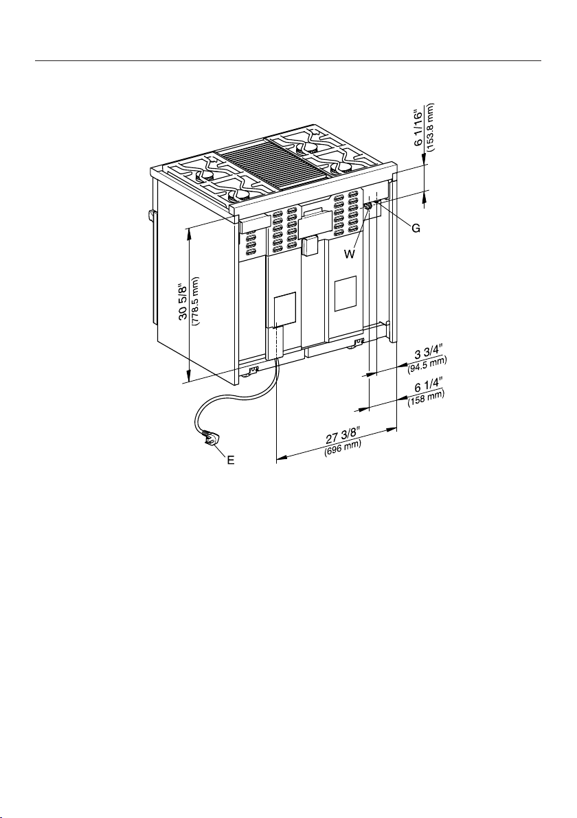
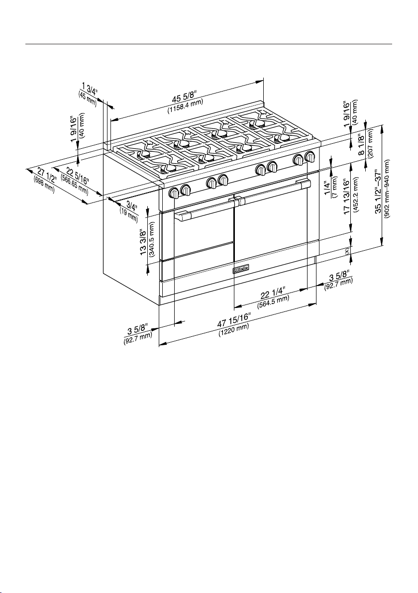
Rear view of HR1134-3AG
E = Electrical connection
G = Gas connection
35

All Gas Range dimensions
*INSTALLATION*
Detailed views of HR1135-3AG
Side view of HR1135-3AG
(x) = Depending on the appliance height adjustment: 5"–61/2"
(127mm–165.1mm)
36
All Gas Range dimensions
*INSTALLATION*
Detailed front side view of HR1135-3AG
37
All Gas Range dimensions
*INSTALLATION*
Front view of HR1135-3AG
(x) = Depending on the appliance height adjustment: 5"–61/2"
(127mm–165.1mm)
38
All Gas Range dimensions
*INSTALLATION*
Rear view of HR1135-3AG
E = Electrical connection
G = Gas connection
39

All Gas Range dimensions
*INSTALLATION*
Detailed views of HR1136-3AG
Side view of HR1136-3AG
(x) = Depending on the appliance height adjustment: 5"–61/2"
(127mm–165.1mm)
40

All Gas Range dimensions
*INSTALLATION*
Detailed front side view of HR1136-3AG
41
All Gas Range dimensions
*INSTALLATION*
Front view of HR1136-3AG
(x) = Depending on the appliance height adjustment: 5"–61/2"
(127mm–165.1mm)
42
All Gas Range dimensions
*INSTALLATION*
Rear view of HR1136-3AG
E = Electrical connection
G = Gas connection
43
All Electric Range dimensions
*INSTALLATION*
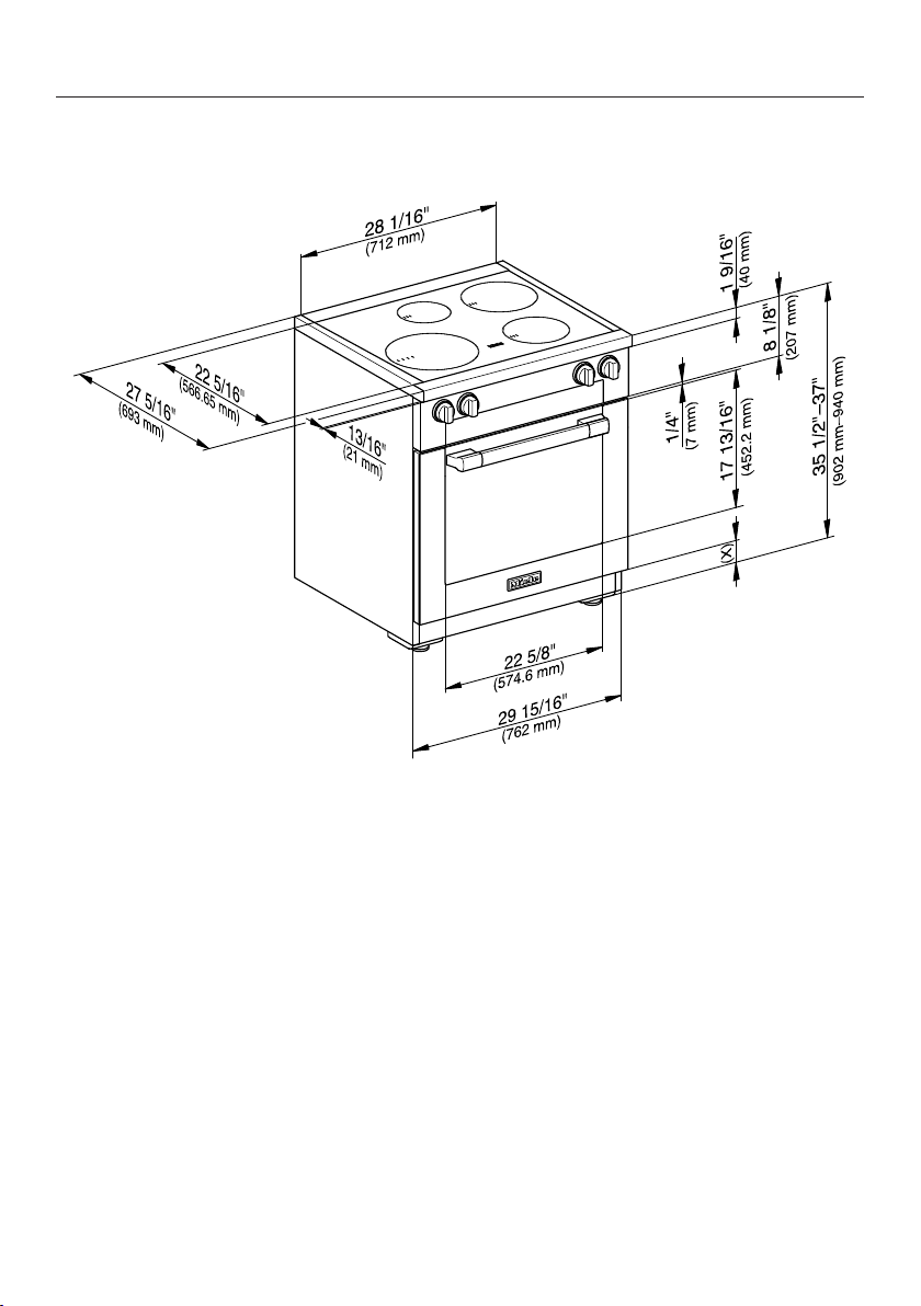
HR1421-3E*, HR1622-3i
, , The shaded area represents the installation area for the connections:
E = Electrical connection,
W = Plumbed water connection (HR1622-3i only)
* Only available in Canada.
44
All Electric Range dimensions
*INSTALLATION*
No. Dimensions Description
13" (330mm) Maximum depth of upper cabinet
18" (547mm) Minimum safety distance to bottom edge of upper
cabinet
35 1/2"–37"
(901–940mm)
Distance from the floor to cooktop surface
min. 30"
(762mm)
Niche width
30" (762mm) Minimum safety distance between the top of the
cooktop surface and the bottom of an unprotected
combustible surface.
or 24" (609mm) Minimum safety distance to a protected
combustible surface or when a Miele Ventilation
Hood is installed.
For all other ventilation hoods please consult the manufacturer’s
specifications for required distances.
approx. 101/16"
(256mm)
Maximum connection width right
and left
Position of
the wall
socket
approx. 41/2"
(115mm)
Maximum connection height
approx. 213/16"
(72mm)
Maximum connection depth
Please observe a minimum safety distance of at least 12" (305mm) from combustible
surfaces located behind the appliance. For zero clearance installation the Miele Backguards
will satisfy the required minimum safety distance to combustible surfaces. The Miele
Backguard is available in 12"(305mm) or 20"(508mm) heights.
45
All Electric Range dimensions
*INSTALLATION*
Detailed views of HR1421-3E
Side view of HR1421-3E
(x) = Depending on the appliance height adjustment: 5"–6 1/2"
(127mm–165.1mm)
46
All Electric Range dimensions
*INSTALLATION*
Detailed front side view of HR1421-3E
47
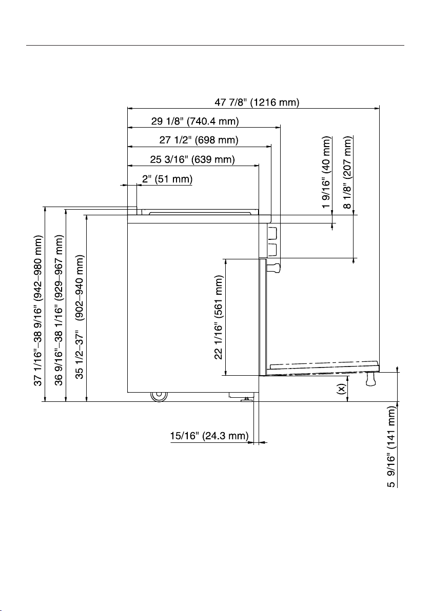
All Electric Range dimensions
*INSTALLATION*
Front view of HR1421-3E
(x) = Depending on the appliance height adjustment: 5"–6 1/2"
(127mm–165.1mm)
48
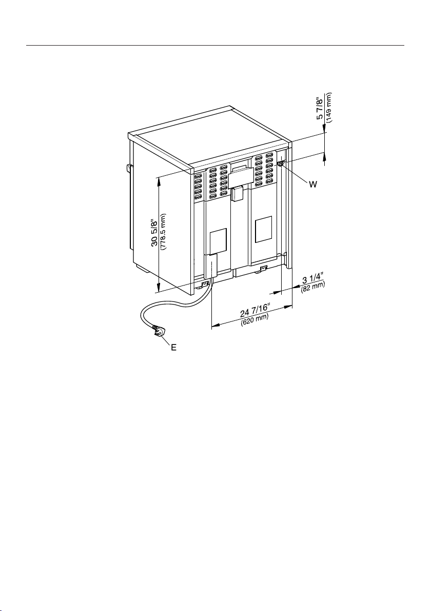
All Electric Range dimensions
*INSTALLATION*
Rear view of HR1421-3E
E = Electrical connection
49
All Electric Range dimensions
*INSTALLATION*
Detailed views of HR1622-3i
Side view of HR1622-3i
(x) = Depending on the appliance height adjustment: 5"–6 1/2"
(127mm–165.1mm)
50
All Electric Range dimensions
*INSTALLATION*
Detailed front side view of HR1622-3i
51
All Electric Range dimensions
*INSTALLATION*
Front view of HR1622-3i
(x) = Depending on the appliance height adjustment: 5"–6 1/2"
(127mm–165.1mm)
52
All Electric Range dimensions
*INSTALLATION*
Rear view of HR1622-3i
E = Electrical connection
W = Plumbed water connection
53

Dual Fuel Range dimensions
*INSTALLATION*
HR1724-3DF
, , The shaded area represents the installation area for the connections:
E = Electrical connection, G = Gas connection
No. Dimensions Description
13" (330mm) Maximum depth of upper cabinet
18" (457mm) Minimum safety distance to bottom edge of upper
cabinet
35 1/2"–37"
(901–940mm)
Distance from the floor to cooktop surface
10" (254mm) Minimum safety distance to combustible surfaces.
54

Dual Fuel Range dimensions
*INSTALLATION*
No. Dimensions Description
min. 30"
(762mm)
Niche width
Please contact Miele Customer Service for more
information.
37" (940mm) Minimum safety distance between the top of the
cooktop surface and the bottom of an unprotected
combustible surface.
30" (762mm) Minimum safety distance between the top of the
cooktop surface and the bottom of the Miele
Ventilation Hood (DAR model with DRxBXL or
DRxBXXL blower).
Refer to the installation instructions for the Miele Ventilation Hood,
“Appliance dimensions” (Distance between cooktop and ventilation
hood (S)).
For all other ventilation hoods please consult the manufacturer’s
specifications for required distances.
approx. 101/16"
(256mm)
Maximum connection width right
and left
Position of
the wall
socket
approx.41/2"
(115mm)
Maximum connection height
approx.213/16"
(72mm)
Maximum connection depth
Please observe a minimum safety distance of at least 12" (305mm) from combustible
surfaces located behind the appliance. For zero clearance installation the Miele Backguards
will satisfy the required minimum safety distance to combustible surfaces. The Miele
Backguard is available in 12"(305mm) or 20"(508mm) heights.
55
Dual Fuel Range dimensions
*INSTALLATION*
Detailed views of HR1724-3DF
Side view of HR1724-3DF
(x) = Depending on the appliance height adjustment: 5"–6 1/2"
(127mm–165.1mm)
56

Dual Fuel Range dimensions
*INSTALLATION*
Detailed front side view of HR1724-3DF
57
Dual Fuel Range dimensions
*INSTALLATION*
Front view of HR1724-3DF
(x) = Depending on the appliance height adjustment: 5"–6 1/2"
(127mm–165.1mm)
58
Dual Fuel Range dimensions
*INSTALLATION*
Rear view of HR1724-3DF
G
E = Electrical connection
G = Gas connection
59

Dual Fuel Range dimensions
*INSTALLATION*
HR1924-3DF
, , The shaded area represents the installation area for the connections:
E = Electrical connection, W = Plumbed water connection, G = Gas connection
No. Dimensions Description
13" (330mm) Maximum depth of upper cabinet
18" (457mm) Minimum safety distance to bottom edge of upper
cabinet
35 1/2"–37"
(901–940mm)
Distance from the floor to cooktop surface
10" (254mm) Minimum safety distance to combustible surfaces.
60

Dual Fuel Range dimensions
*INSTALLATION*
No. Dimensions Description
min. 30"
(762mm)
Niche width
Please contact Miele Customer Service for more
information.
37" (940mm) Minimum safety distance between the top of the
cooktop surface and the bottom of an unprotected
combustible surface.
30" (762mm) Minimum safety distance between the top of the
cooktop surface and the bottom of the Miele
Ventilation Hood (DAR model with DRxBXL or
DRxBXXL blower).
Refer to the installation instructions for the Miele Ventilation Hood,
“Appliance dimensions” (Distance between cooktop and ventilation
hood (S)).
For all other ventilation hoods please consult the manufacturer’s
specifications for required distances.
approx. 101/16"
(256mm)
Maximum connection width right
and left
Position of
the wall
socket
approx.41/2"
(115mm)
Maximum connection height
approx.213/16"
(72mm)
Maximum connection depth
Please observe a minimum safety distance of at least 12" (305mm) from combustible
surfaces located behind the appliance. For zero clearance installation the Miele Backguards
will satisfy the required minimum safety distance to combustible surfaces. The Miele
Backguard is available in 12"(305mm) or 20"(508mm) heights.
61

Dual Fuel Range dimensions
*INSTALLATION*
Detailed views of HR1924-3DF
Side view of HR1924-3DF
(x) = Depending on the appliance height adjustment: 5"–6 1/2"
(127mm–165.1mm)
62

Dual Fuel Range dimensions
*INSTALLATION*
Detailed front side view of HR1924-3DF
63
Dual Fuel Range dimensions
*INSTALLATION*
Front view of HR1924-3DF
(x) = Depending on the appliance height adjustment: 5"–6 1/2"
(127mm–165.1mm)
64

Dual Fuel Range dimensions
*INSTALLATION*
Rear view of HR1924-3DF
E = Electrical connection
W = Plumbed water connection
G = Gas connection
65
Dual Fuel Range dimensions
*INSTALLATION*
HR1934-3DF, HR1935-3DF, HR1936-3DF
, , The shaded area represents the installation area for the connections:
E = Electrical connection, W = Plumbed water connection, G = Gas connection
No. Dimensions Description
13" (330mm) Maximum depth of upper cabinet
18" (457mm) Minimum safety distance to bottom edge of upper
cabinet
35 1/2"–37"
(901–940mm)
Distance from the floor to cooktop surface
10" (254mm) Minimum safety distance to combustible surfaces.
66

Dual Fuel Range dimensions
*INSTALLATION*
HR1934-3DF
No. Dimensions Description
min. 36"
(915mm)
Niche width
Please contact Miele Customer Service for more
information.
37" (940mm) Minimum safety distance between the top of the
cooktop surface and the bottom of an unprotected
combustible surface.
36" (915mm) Minimum safety distance between the top of the
cooktop surface and the bottom of the Miele
Ventilation Hood (DAR model with DRxBXL
blower).
30" (762mm) Minimum safety distance between the top of the
cooktop surface and the bottom of the Miele
Ventilation Hood (DAR model with DRxBXXL
blower).
Refer to the installation instructions for the Miele Ventilation Hood,
“Appliance dimensions” (Distance between cooktop and ventilation
hood (S)).
For all other ventilation hoods please consult the manufacturer’s
specifications for required distances.
approx. 131/16"
(332.5mm)
Maximum connection width right
and left
Position of
the wall
socket
approx.41/2"
(115mm)
Maximum connection height
approx. 213/16"
(72mm)
Maximum connection depth
Please observe a minimum safety distance of at least 12" (305mm) from combustible
surfaces located behind the appliance. For zero clearance installation the Miele Backguards
will satisfy the required minimum safety distance to combustible surfaces. The Miele
Backguard is available in 12"(305mm) or 20"(508mm) heights.
67

Dual Fuel Range dimensions
*INSTALLATION*
HR1935-3DF, HR1936-3DF
No. Dimensions Description
min. 36"
(915mm)
Niche width
Please contact Miele Customer Service for more
information.
37" (940mm) Minimum safety distance between the top of the
cooktop surface and the bottom of an unprotected
combustible surface.
30" (762mm) Minimum safety distance between the top of the
cooktop surface and the bottom of the Miele
Ventilation Hood (DAR model with DRxBXL or
DRxBXXL blower).
Refer to the installation instructions for the Miele Ventilation Hood,
“Appliance dimensions” (Distance between cooktop and ventilation
hood (S)).
For all other ventilation hoods please consult the manufacturer’s
specifications for required distances.
approx. 131/16"
(332.5mm)
Maximum connection width right
and left
Position of
the wall
socket
approx.41/2"
(115mm)
Maximum connection height
approx. 213/16"
(72mm)
Maximum connection depth
Please observe a minimum safety distance of at least 12" (305mm) from combustible
surfaces located behind the appliance. For zero clearance installation the Miele Backguards
will satisfy the required minimum safety distance to combustible surfaces. The Miele
Backguard is available in 12"(305mm) or 20"(508mm) heights.
68

Dual Fuel Range dimensions
*INSTALLATION*
Detailed views of HR1934-3DF
Side view of HR1934-3DF
(x) = Depending on the appliance height adjustment: 5"–61/2"
(127mm–165.1mm)
69

Dual Fuel Range dimensions
*INSTALLATION*
Detailed front side view of HR1934-3DF
70
Dual Fuel Range dimensions
*INSTALLATION*
Front view of HR1934-3DF
(x) = Depending on the appliance height adjustment: 5"–61/2"
(127mm–165.1mm)
71

Dual Fuel Range dimensions
*INSTALLATION*
Rear view of HR1934-3DF
E = Electrical connection
W = Plumbed water connection
G = Gas connection
72

Dual Fuel Range dimensions
*INSTALLATION*
Detailed views of HR1935-3DF
Side view of HR1935-3DF
(x) = Depending on the appliance height adjustment: 5"–61/2"
(127mm–165.1mm)
73

Dual Fuel Range dimensions
*INSTALLATION*
Detailed front side view of HR1935-3DF
74
Dual Fuel Range dimensions
*INSTALLATION*
Front view of HR1935-3DF
(x) = Depending on the appliance height adjustment: 5"–61/2"
(127mm–165.1mm)
75
Dual Fuel Range dimensions
*INSTALLATION*
Rear view of HR1935-3DF
E = Electrical connection
W = Plumbed water connection
G = Gas connection
76
Dual Fuel Range dimensions
*INSTALLATION*
Detailed views of HR1936-3DF
Side view of HR1936-3DF
(x) = Depending on the appliance height adjustment: 5"–61/2"
(127mm–165.1mm)
77

Dual Fuel Range dimensions
*INSTALLATION*
Detailed front side view of HR1936-3DF
78
Dual Fuel Range dimensions
*INSTALLATION*
Front view of HR1936-3DF
(x) = Depending on the appliance height adjustment: 5"–61/2"
(127mm–165.1mm)
79
Dual Fuel Range dimensions
*INSTALLATION*
Rear view of HR1936-3DF
E = Electrical connection
W = Plumbed water connection
G = Gas connection
80

Dual Fuel Range dimensions
*INSTALLATION*
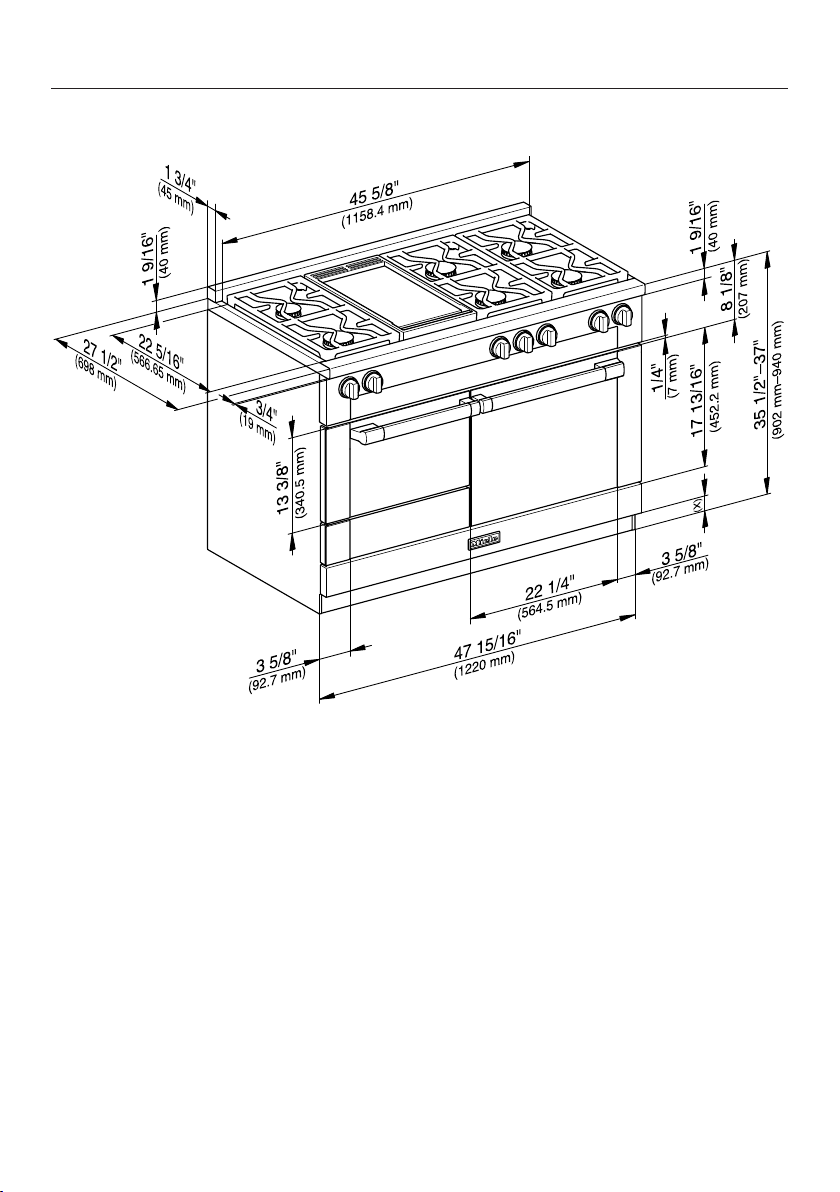
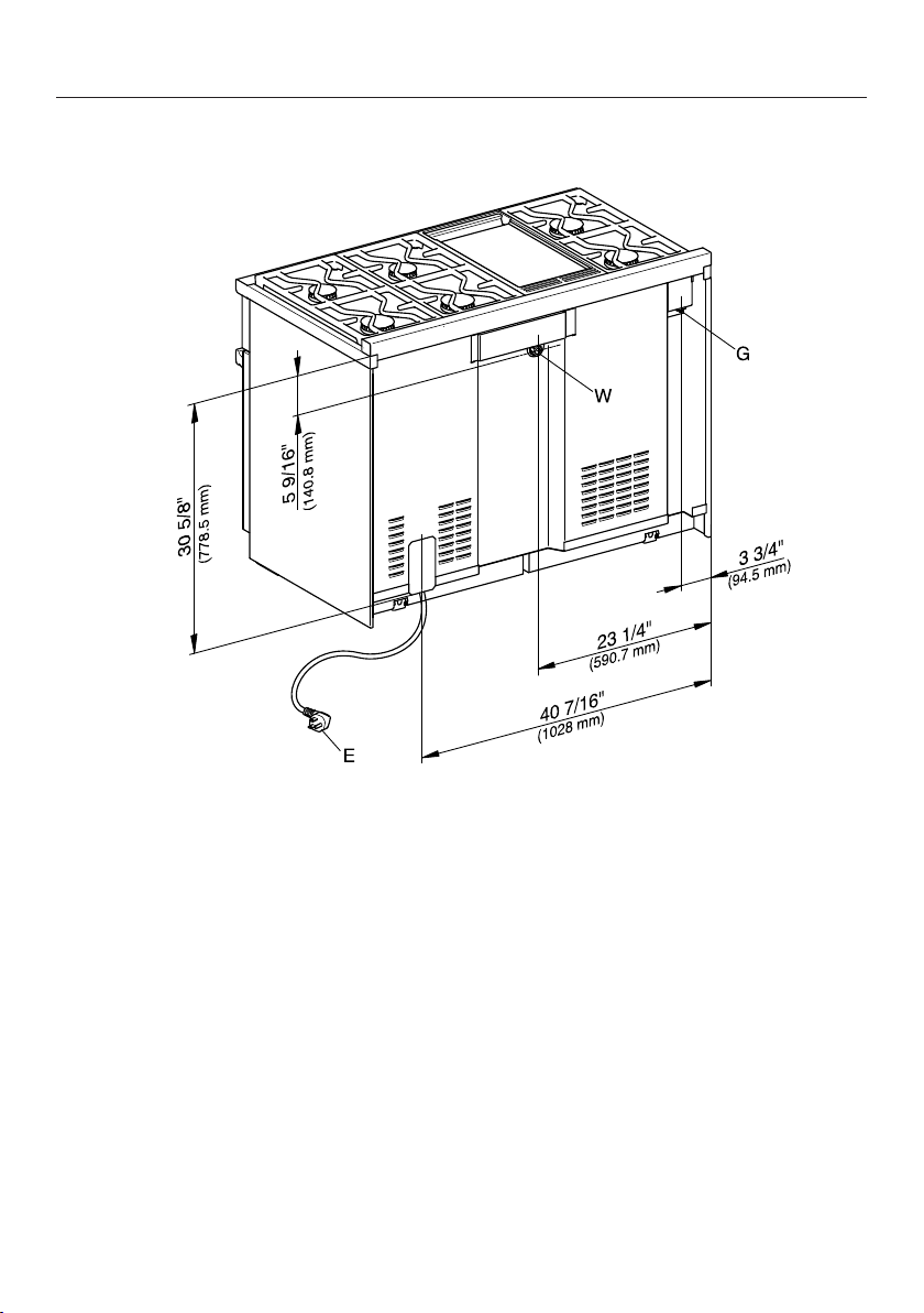
HR1954-3DF, HR1955-3DF, HR1956-3DF
, , The shaded area represents the installation area for the connections:
E = Electrical connection, W = Plumbed water connection, G = Gas connection
No. Dimensions Description
13" (330mm) Maximum depth of upper cabinet
18" (457mm) Minimum safety distance to bottom edge of upper
cabinet
35 1/2"–37"
(901–940mm)
Distance from the floor to cooktop surface
10" (254mm) Minimum safety distance to combustible surfaces.
81
Dual Fuel Range dimensions
*INSTALLATION*
HR1954-3DF
No. Dimensions Description
min. 48"
(1,220mm)
Niche width
Please contact Miele Customer Service for more
information.
37" (940mm) Minimum safety distance between the top of the
cooktop surface and the bottom of an unprotected
combustible surface.
36" (915mm) Minimum safety distance between the top of the
cooktop surface and the bottom of the Miele
Ventilation Hood (DAR model with DRxBXXL
blower).
Refer to the installation instructions for the Miele Ventilation Hood,
“Appliance dimensions” (Distance between cooktop and ventilation
hood (S)).
For all other ventilation hoods please consult the manufacturer’s
specifications for required distances.
approx. 191/8"
(485mm)
Maximum connection width right
and left
Position of
the wall
socket
approx.31/2"
(90mm)
Maximum connection height
approx. 213/16"
(72mm)
Maximum connection depth
Please observe a minimum safety distance of at least 12" (305mm) from combustible
surfaces located behind the appliance. For zero clearance installation the Miele Backguards
will satisfy the required minimum safety distance to combustible surfaces. The Miele
Backguard is available in 12"(305mm) or 20"(508mm) heights.
82

Dual Fuel Range dimensions
*INSTALLATION*
HR1955-3DF, HR1956-3DF
No. Dimensions Description
min. 48"
(1,220mm)
Niche width
Please contact Miele Customer Service for more
information.
37" (940mm) Minimum safety distance between the top of the
cooktop surface and the bottom of an unprotected
combustible surface.
36" (915mm) Minimum safety distance between the top of the
cooktop surface and the bottom of the Miele
Ventilation Hood (DAR model with DRxBXL
blower).
30" (762mm) Minimum safety distance between the top of the
cooktop surface and the bottom of the Miele
Ventilation Hood (DAR model with DRxBXXL
blower).
Refer to the installation instructions for the Miele Ventilation Hood,
“Appliance dimensions” (Distance between cooktop and ventilation
hood (S)).
For all other ventilation hoods please consult the manufacturer’s
specifications for required distances.
approx. 191/8"
(485mm)
Maximum connection width right
and left
Position of
the wall
socket
approx.31/2"
(90mm)
Maximum connection height
approx. 213/16"
(72mm)
Maximum connection depth
Please observe a minimum safety distance of at least 12" (305mm) from combustible
surfaces located behind the appliance. For zero clearance installation the Miele Backguards
will satisfy the required minimum safety distance to combustible surfaces. The Miele
Backguard is available in 12"(305mm) or 20"(508mm) heights.
83

Dual Fuel Range dimensions
*INSTALLATION*
Detailed views of HR1954-3DF
Side view of HR1954-3DF
(x) = Depending on the appliance height adjustment: 4"–51/2"
(101.6mm–139.7mm)
84

Dual Fuel Range dimensions
*INSTALLATION*
Detailed front side view of HR1954-3DF
85
Dual Fuel Range dimensions
*INSTALLATION*
Front view of HR1954-3DF
(x) = Depending on the appliance height adjustment: 4"–51/2"
(101.6mm–139.7mm)
86
Dual Fuel Range dimensions
*INSTALLATION*
Rear view of HR1954-3DF
E = Electrical connection
W = Plumbed water connection
G = Gas connection
87
Dual Fuel Range dimensions
*INSTALLATION*
Detailed views of HR1955-3DF
Side view of HR1955-3DF
(x) = Depending on the appliance height adjustment: 4"–51/2"
(101.6mm–139.7mm)
88
Dual Fuel Range dimensions
*INSTALLATION*
Detailed front side view of HR1955-3DF
89
Dual Fuel Range dimensions
*INSTALLATION*
Front view of HR1955-3DF
(x) = Depending on the appliance height adjustment: 4"–51/2"
(101.6mm–139.7mm)
90
Dual Fuel Range dimensions
*INSTALLATION*
Rear view of HR1955-3DF
E = Electrical connection
W = Plumbed water connection
G = Gas connection
91

Dual Fuel Range dimensions
*INSTALLATION*
Detailed views of HR1956-3DF
Side view of HR1956-3DF
(x) = Depending on the appliance height adjustment: 4"–51/2"
(101.6mm–139.7mm)
92

Dual Fuel Range dimensions
*INSTALLATION*
Detailed front side view of HR1956-3DF
93
Dual Fuel Range dimensions
*INSTALLATION*
Front view of HR1956-3DF
(x) = Depending on the appliance height adjustment: 4"–51/2"
(101.6mm–139.7mm)
94
Dual Fuel Range dimensions
*INSTALLATION*
Rear view of HR1956-3DF
E = Electrical connection
W = Plumbed water connection
G = Gas connection
95
Anti-tip device
*INSTALLATION*
96
Before installation
WARNING
Children and adults can tip over the
range if has not been secured. This
may lead to fatal injuries.
Make sure that the anti-tip device is
properly installed and locked into
place. It should be screwed to the
floor or wall and engage with the
center of the bottom of the range.
You must take care to protect the
installed flooring when moving the
range.
After moving the range, make sure
that the anti-tip device locks back
into place. It should be screwed to
the floor or wall and engage with the
center of the bottom of the range.
Do not use the range if the anti-tip
device has not been properly
installed and engaged.
Due to the size and weight of the
appliance, installation should be
carried out by two people.
Any opening in the wall behind the
appliance and in the floor under the
appliance shall be sealed.
We recommend removing the oven
door before installing the range (see
“Removing the door” in the Operating
Instructions) and all accessories from
the oven interior. This will make it
easier to install the appliance in its
designated space.
Once the range has been installed and
secured against tipping, you can
reattach the oven door (see
“Reinstalling the door” in the
Operating Instructions).
Anti-tip device
*INSTALLATION*
Do not carry or lift the range by the oven door handle or the control panel!
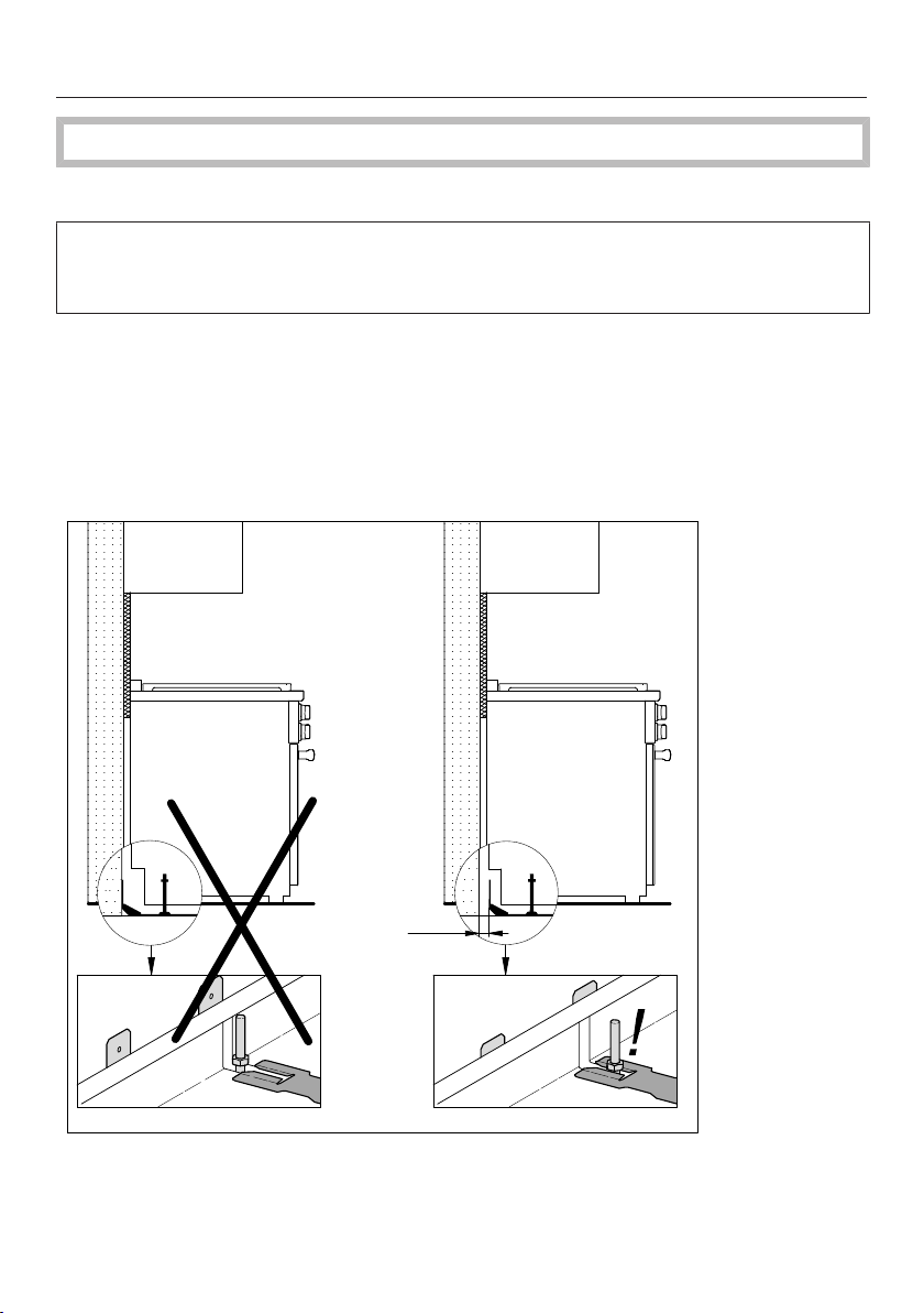
Checking the installation niche
Install the anti-tip device on a surface capable of bearing significant weight, such
as a concrete floor, concrete wall, or timber framing. The surface must be flat and
level.
If the rear of the Range has distance A to the supporting wall due to
unevenness or wall covering (e.g., tile level), you must install the anti-tip device
to the supporting floor. Alternatively, you can also install the anti-tip device with
an adapter between the supporting wall and the anti-tip device. The adapter
must compensate dimension A and be made of suitable material so that a
supporting connection is made between the wall and anti-tip device. Use
appropriate screws (length and diameter).
A
A = Distance between the rear of the Range and the supporting wall
97

Anti-tip device
*INSTALLATION*
Check the floor surface.
Check the installation dimensions.
Check the building drawings for supply wires and pipework. Make sure that you
do not damage any wires or pipes when drilling holes to attach the anti-tip
device.
Check the position of the electrical, gas, and plumbed water connections (see
“Electrical connection”, “Gas Connection”, and “Plumbed water connection”). An
overview of electrical and gas connections required for your Range can be found
in “Notes on installation”.
98
Anti-tip device
*INSTALLATION*
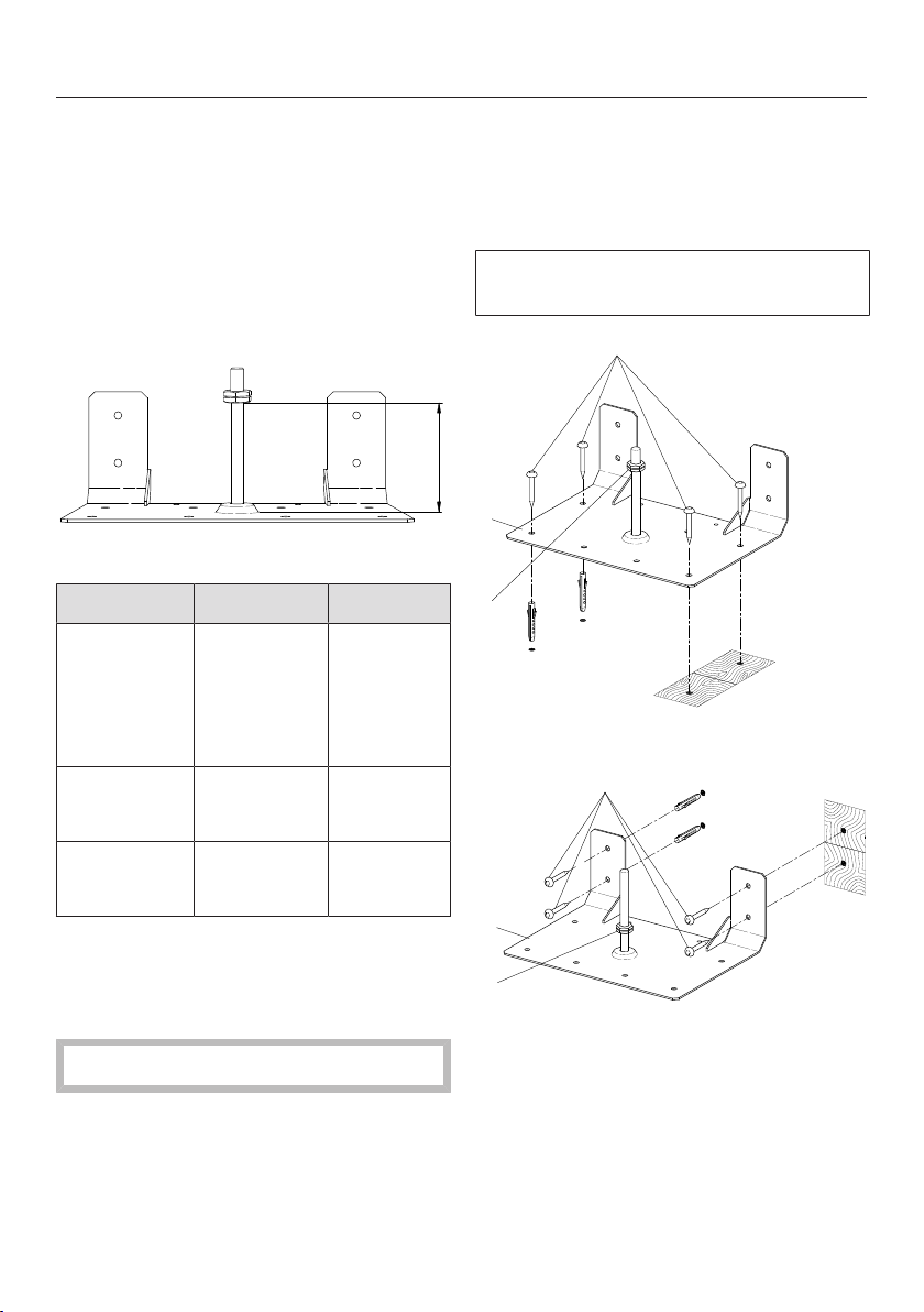
99
Included accessories
- 1 anti-tip device
- 4 screws
- 4 plugs
Installation dimensions of
locking bolt
X
Anti-tip device, front view
Model Width X
HR1124-3
HR1421-3*
HR1622-3
HR1724-3
HR1924-3
2915/16"
(762mm)
313/16"
(97mm)
HR113x-3
HR193x-3
3515/16"
(915mm)
313/16"
(97mm)
HR195x-3 4715/16"
(1,220mm)
31/4"
(82mm)
* Only available in Canada.
Installing the Range with the
anti-tip device
Wear safety shoes and gloves.
The anti-tip device should be installed
at the bottom rear of the Range at the
midpoint of the width.
Measure the installation space for the
Range close to floor level.
Mark the wall at the middle of the
space width.
Position the notch of the anti-tip
device on the wall marking.
The anti-tip device must fit tightly on
the floor or the wall.
1
3
2
Attaching to the floor
1
2
3
Attaching to the wall
a
Anti-tip device
b
Screws
c
Locking nut
Anti-tip device
*INSTALLATION*
100
Using four screws , secure the anti-
tip device to the floor surface with
suitable bearing capacity, either to
the floor or wall.
Screw the locking nut to the bolt;
see the “Installation dimensions of
locking bolt” table.
Do not push the Range into
position before all supply
connections have been
established.
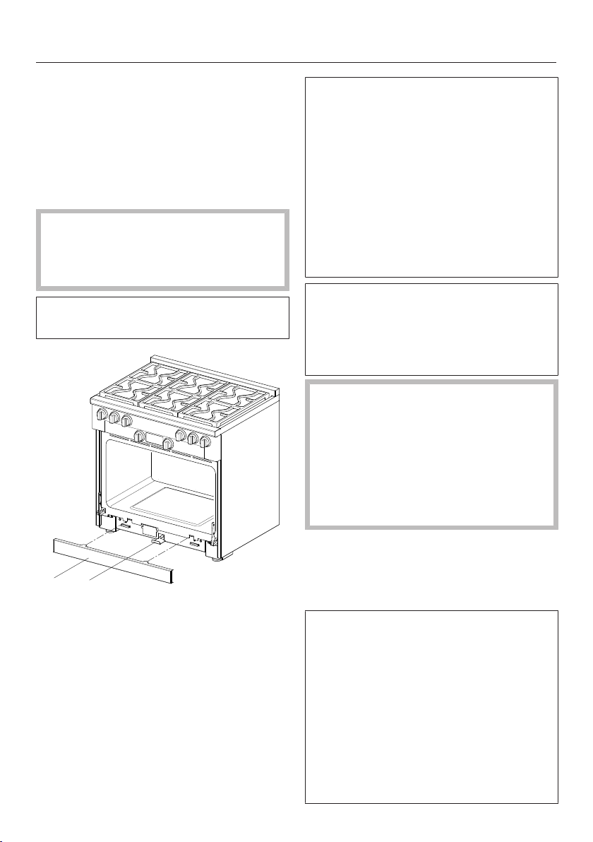
The toe kick panel is attached to the
toe kick of the Range by magnets.
21
a
Toe kick panel
b
Locking clamp
Remove the toe kick panel from
the Range.
Pull out the locking clamp .
The locking clamp extends through
the toe kick panel of the Range
housing. It can be pulled out and
pushed back in again. Its length is
approximately equal to the depth of
the Range.
A slot is located in the non-visible rear
section of the locking latch. This slot
engages with the bolt of the anti-tip
device when you slide the locking
latch into the Range.
Complete all necessary connections
for the Range. Read the information in
the “Electrical connection”, “Gas
connection”, and “Plumbed water
connection” sections.
The Range can be damaged if it is
lifted using the panel, the island trim,
or the door handle.
Open the oven door and hold the
appliance by the front of the oven
cavity.
Lift the Range and move it with the
help of the rear wheels.
Slide the Range into position, guiding
the middle of the appliance onto the
anti-tip device. Slide the appliance all
the way back to the wall.
The Range can be aligned if
necessary. Check it with a level.
- Rear adjustment right and left:
You will need an open-end wrench
(3/8" (10mm)).
-
Front adjustment right and left:
You will need an open-end wrench
(5/8" (16mm)) for the locknut and
an open-end wrench (1/2" (13mm))
for the adjustable nut.
Anti-tip device
*INSTALLATION*
101
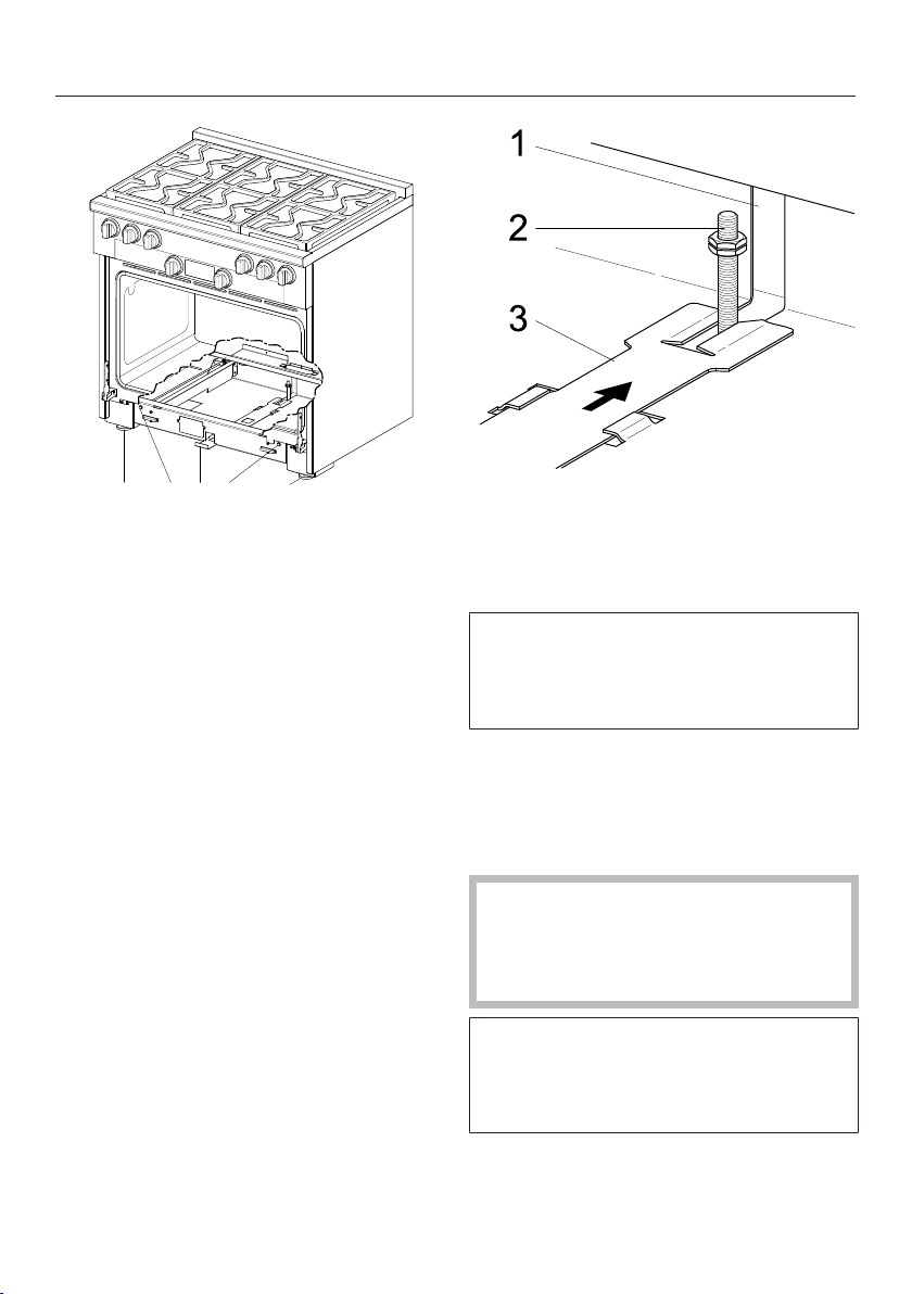
1 22 33
a
Locking clamp
b
Rear adjustment
c
Front adjustment
Align the Range.
Slide the locking clamp firmly
back.
In the Range housing, there is an
opening for the bolt of the anti-tip
device. The opening allows the Range
to be slid onto the anti-tip device and
back to the wall.
The locking clamp must noticeably
engage with the bolt so that anti-tip
protection is ensured for the Range.
a
Opening in the Range housing
b
Anti-tip device bolt
c
Locking clamp with slot
The toe kick panel can only be
attached if the locking clamp has
been slid all the way into the
appliance.
Secure the toe kick panel onto the
Range.
Disconnecting the range from
the anti-tip device
WARNING
Children and adults can tip over the
range if has not been secured. This
may lead to fatal injuries.
If you need to remove the range from
its installation space, e.g. for service,
you first need to disconnect the
appliance from the anti-tip device.
Follow the instructions for installation
in reverse order.
Plumbed water connection
102
Risk of injury and appliance
damage if appliance is not
connected properly.
Failing to connect the appliance
properly can result in personal injury
and/or material damage.
The appliance may only be
connected to the plumbed water
connection by qualified technicians.
Risk to health and risk of
damage due to contaminated water.
The quality of the incoming water
must conform to the requirements for
drinking water in the country where
the appliance is being used.
Connect the appliance to the water
supply.
Connection to the water supply must
comply with the applicable
regulations in the country where the
appliance is being installed. All units
and systems used to supply water to
the appliance must also comply with
the applicable regulations in the
respective country.
Connect the appliance directly to the
plumbed water supply.
Avoid connecting the appliance to a
water supply in which the water
might stagnate. Otherwise, the flavor
of the food could be impaired.
The appliance must only be
connected to a cold water supply.
The appliance is constructed to comply
with the relevant local and national
safety standards and may be
connected to the water supply without
a non-return valve if national regulations
permit.
The water connection pressure needs
to be between 14.5and 145psi (1and
10bar). If the pressure is higher than
this, install a pressure reducing valve.
30" and 36" range: The provided
stainless steel hose has a length of
4'11" (1.5m).
48" range: The provided stainless steel
hose has a length of 9'10" (3m).
Longer inlet hoses are available if
necessary. Do not shorten the hoses.
Longer inlet hoses are available if
necessary. Do not shorten the hoses.
The total hose length must not exceed
24.5ft (7.5m).
A faucet must be provided between the
stainless steel hose and the household
water supply to ensure that the water
supply can be cut off if necessary.
Make sure the faucet remains easily
accessible once the appliance has been
installed.
If the stainless steel hose supplied is
damaged, it must only be replaced
with an original Miele replacement
hose, available from the Miele web
store, Miele Customer Service, or
from your Miele dealer. The hose
must be suitable for supplying
drinking water.

Plumbed water connection
103
Connecting the appliance to
the water supply line
Make sure that the supply line is not
kinked or damaged.
Remove the water connection cover
at the back of the appliance.
Take the angled side of the brass
fitting and check whether a gasket is
present. If not, insert one.
Screw the supply line coupling nut
onto the threaded union.
Ensure that the supply line is
correctly fitted and that it is water-
tight.
Connecting to the water supply
Disconnect the appliance from the
power supply before connecting it to
the water supply.
Turn off the water supply at the
faucet before connecting the
appliance to the water supply.
Make sure that the faucet remains
accessible after the appliance has
been installed.
A faucet with a 3/8" connection thread
is required for the connection.
Connect the stainless steel hose to
the water supply.
Old or used hoses must not be
connected to the appliance.
Only use the stainless steel hose
supplied.
Connect the compression fitting to
the water supply.
Slowly open the shut-off valve to the
water supply and check for leaks. If
necessary, check whether the sealing
ring and fittings are tight.
You can now continue installing the
appliance.
Electrical connection
*INSTALLATION*
104
The plug must be inserted into a
suitable outlet that has been installed
and grounded in compliance with all
applicable local regulations.
WARNING: THIS APPLIANCE MUST
BE GROUNDED
Installer: Please pass these
instructions on to the customer.
WARNING:
During installation, maintenance, and
repair work, the Range must be
disconnected from the domestic
electrical supply by fully unscrewing
the breakers, switching off the
breakers, and unplugging the power
cord from the socket. To do this, pull
the plug, not the power cord.
Installation, repairs, and other work
by unqualified persons could be
dangerous. Miele cannot be held
liable for unauthorized work.
Installation, maintenance, and repairs
must only be carried out by a Miele
authorized technician.
The connection data (voltage and
frequency) on the data tag of the
Range must match the domestic
electrical supply in order to avoid the
risk of damage to the Range.
Compare this data before connecting
the appliance. If in any doubt,
consult a qualified electrician.
The internal electrical wiring of the
appliance was carried out and tested
in accordance with the current
regulations. To make sure that your
appliance runs smoothly, ensure that
the socket has the correct phase
assignment. If in any doubt, consult
a qualified electrician.
Electrical connection
*INSTALLATION*
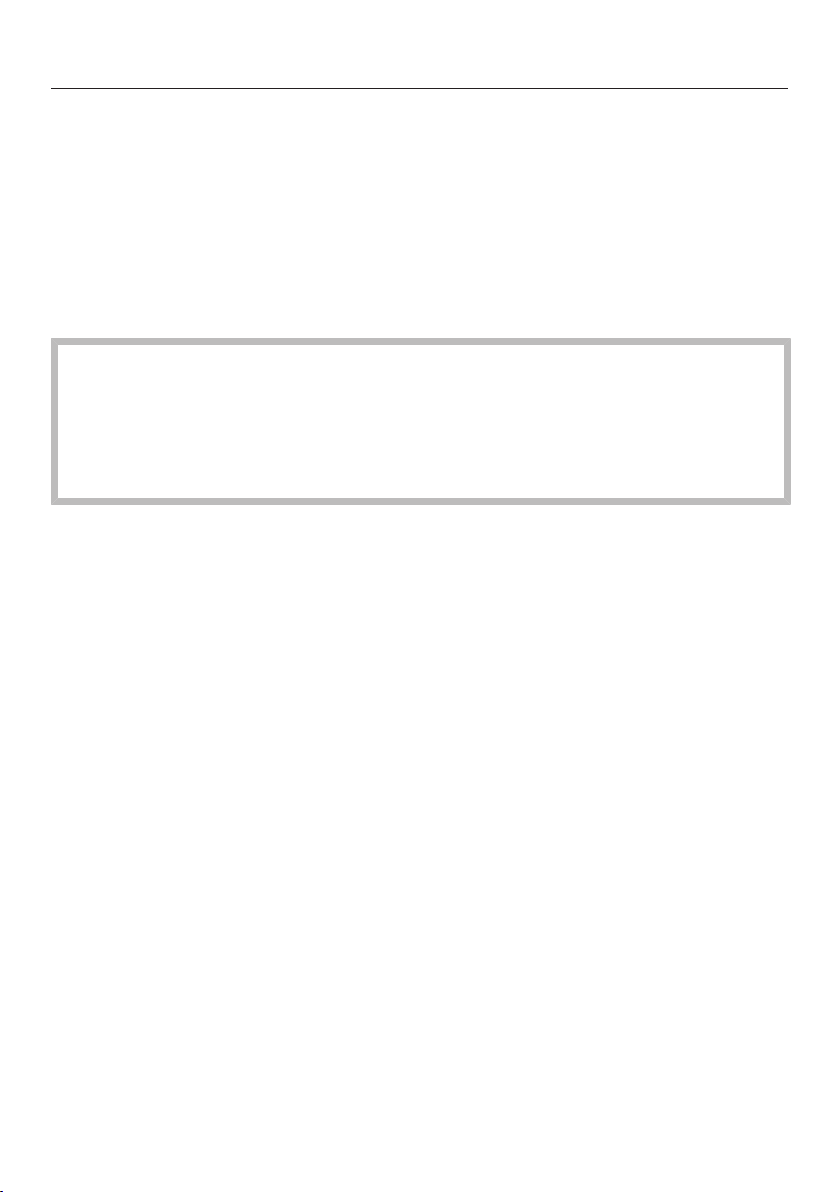
Electrical connection
Model Power cord NEMA For electrical supply with
USA Canada
HR112x-3AG
HR113x-3AG
approx.
5'11"
(1.80m)
5–15
P plug
120V 15A 15A 60Hz
HR1421-3E
Only available
in Canada.
approx.
5'11"
(1.80m)
14–50
P plug
120/208V
or
120/240V
50A 50A 60Hz
HR1622-3i approx.
5'11"
(1.80m)
14–50
P plug
120/208V
or
120/240V
50A 50A 60Hz
HR172x-3DF
HR192x-3DF
HR193x-3DF
approx.
5'11"
(1.80m)
14–30
P plug
120/208V
or
120/240V
30A 30A 60Hz
HR195x-3DF approx.
5'11"
(1.80m)
14–50
P plug
120/208V
or
120/240V
50A 50A 60Hz
Temporary or permanent operation on an autonomous power supply system or a
power supply system that is not synchronized with the grid power supply (e.g.,
island networks, back-up systems) is possible. A prerequisite for operation is that
the power supply system complies with the specifications of EN50160 or an
equivalent standard. The function and operation of the protective measures
provided in the domestic electrical installation and in this Miele product must also
be maintained in isolated operation or in operation that is not synchronized with
the grid power supply, or these measures must be replaced by equivalent
measures in the installation. As described, for example, in the current version of
VDE-AR-E 2510-2.
105
Electrical connection
*INSTALLATION*
Data plate
The data plate is located behind the toe kick panel. The toe kick panel is attached
to the toe kick of the Range by magnets so it can be removed and put back again
easily.
There you can find the model number, serial number and the connection data
(voltage/frequency/maximum rated load) for your Range.
Have this information available if you need to contact Miele so that any issues can
be rectified as quickly as possible.
This appliance must be grounded in compliance with all applicable local and
national regulations.
Installation, repair and maintenance work should only be performed by a Miele
authorized service technician in compliance with local regulations and the ANSI
National Electrical Code / NFPA 70 in the United States or the Canadian
Electrical Code, Part I in Canada (CSA standard C22.1).
SAVE THESE INSTRUCTIONS FOR THE ELECTRICAL INSPECTOR'S USE.
106
Gas connection
*INSTALLATION*
107
Connection to the gas supply
should only be undertaken by an
approved and registered gas
installer.
In Massachusetts, the gas
connection may be performed only
by a certified gas installer.
The Range must be connected with
its own faucet.
The gas connection must be
installed so that connection can be
made either from inside or outside
the kitchen unit. The faucet must be
easily accessible and visible (by
opening the door panel if necessary).
The connection of the Range can be
for natural gas NG or liquid propane
LP according to the model.
Ask your gas company what kind of
gas is used and compare it with the
specifications on the data tag.
The Range is not connected to an
exhaust vent.
During the setup and connection of
the Range, observe the applicable
installation conditions, especially
suitable ventilation measures.
The gas connections must be
arranged in such a way that they are
not heated and damaged by the
operation of the Range.
In particular, make sure that the gas
hose lines and connection fittings on
the Range do not come into contact
with hot exhaust gases.
Flexible connection lines can be
damaged by incorrect routing.
Attach flexible connection lines in
such a way that they do not come
into contact with any moving kitchen
parts (e.g., a drawer) and are not
exposed to mechanical stress.
The Range and the faucet must be
disconnected from the gas supply
during a gas pressure test.
Disconnect the Range and the faucet
from the gas supply before
performing a gas pressure test at a
pressure of more than 1/2psi
(3.5kPA). Close the faucet of the gas
supply before performing a gas
pressure test at a pressure of less
than or equal to 1/2psi (3.5kPA).
For the gas connection, note that it is
a 1/2" NPT thread. Incorrectly sealed
gas lines can lead to a gas leak and
thus to an explosion.
Seal all gas lines with a suitable
thread sealant.
Seal tightness tests on the Range
must be performed according to
manufacturer specifications.
The gas connection must be carried
out by a Miele authorized technician
in accordance with local regulations
and the following codes:
National Fuel Gas Code ANSIZ21.1/
NFPA No. 54 for the United States or
the current Can/CGAB149.1 and 2
Installation Codes of Gas Appliances
for Canada.
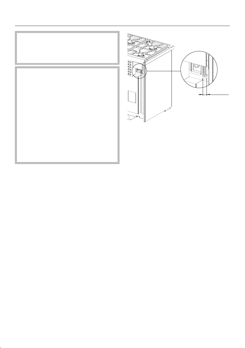
Gas connection
*INSTALLATION*
108
The installation must comply with
local regulations or, if there are no
local regulations, the National Fuel
Gas Code, ANSIZ223.1/NFPA54.
The gas pressure may not
undershoot or exceed certain values.
Make sure that the maximum gas
pressure upstream of the gas
pressure controller does not amount
to more than 1/2psi (3.5kPA) for
natural gas NG and liquid propane
LP.
Make sure that the minimum gas
pressure amounts to a 6" water head
in the case of natural gas and a 11"
water head in the case of propane
gas.
1/2" NPT
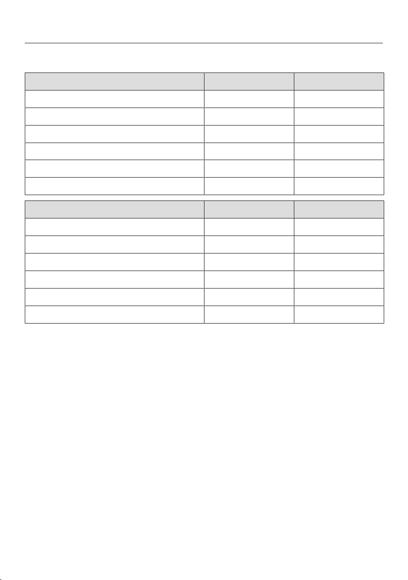
Burner ratings
*INSTALLATION*
Burner ratings HR1124-3AG
Natural gas NG Btu/hr kW
Simmer burner 12,500 3.7
Power burner 19,500 5.7
Browning burner 22,000 6.4
Bake burner 23,200 6.8
Total cooktop output 71,000 20.8
Maximum total output of Range 94,200 27.6
Liquid propane LP Btu/hr kW
Simmer burner 12,500 3.7
Power burner 19,500 5.7
Browning burner 20,150 5.9
Bake burner 23,200 6.8
Total cooktop output 71,000 20.8
Maximum total output of Range 94,200 27.6
109
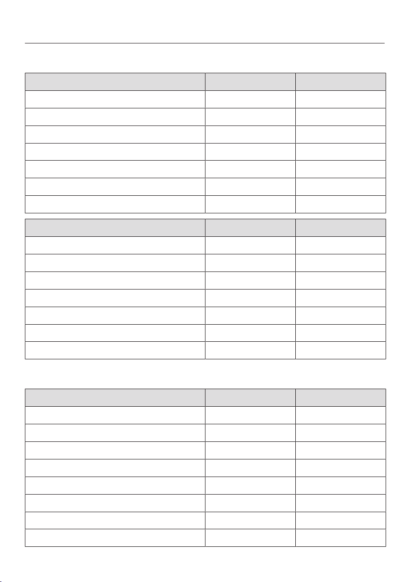
Burner ratings
*INSTALLATION*
Burner ratings HR1134-3AG
Natural gas NG Btu/hr kW
Simmer burner 8,000 2.3
Power burner, rear 9,000 2.6
Power burner, front 19,500 5.7
Browning burner 22,000 6.4
Bake burner 25,500 7.5
Total cooktop output 84,500 24.8
Maximum total output of Range 110,000 32.2
Liquid propane LP Btu/hr kW
Simmer burner 8,000 2.3
Power burner, rear 9,000 2.6
Power burner, front 19,500 5.7
Browning burner 20,150 5.9
Bake burner 27,500 8.1
Total cooktop output 84,500 24.8
Maximum total output of Range 112,000 32.8
Burner ratings HR1135-3AG
Natural gas NG Btu/hr kW
Simmer burner 8,000 2.3
Power burner, rear 9,000 2.6
Power burner, front 19,500 5.7
Grill 19,000 5.6
Browning burner 22,000 6.4
Bake burner 25,500 7.5
Total cooktop output 75,000 22.0
Maximum total output of Range 100,500 29.5
110
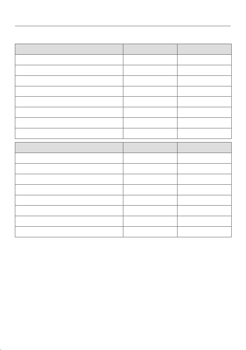
Burner ratings
*INSTALLATION*
Burner ratings HR1136-3AG
Natural gas NG Btu/hr kW
Simmer burner 8,000 2.3
Power burner, rear 9,000 2.6
Power burner, front 19,500 5.7
Griddle plate 13,000 3.8
Browning burner 22,000 6.4
Bake burner 25,500 7.5
Total cooktop output 69,000 20.2
Maximum total output of Range 94,500 27.7
Liquid propane LP Btu/hr kW
Simmer burner 8,000 2.3
Power burner, rear 9,000 2.6
Power burner, front 19,500 5.7
Griddle plate 13,000 3.8
Browning burner 20,150 5.9
Bake burner 27,500 8.1
Total cooktop output 69,000 20.2
Maximum total output of Range 96,500 28.3
111
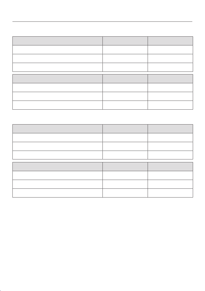
Burner ratings
*INSTALLATION*
Burner ratings HR1724-3DF
Natural gas NG Btu/hr kW
Simmer burner 12,500 3.7
Power burner 19,500 5.7
Total cooktop output 71,000 20.8
Liquid propane LP Btu/hr kW
Simmer burner 12,500 3.7
Power burner 19,500 5.7
Total cooktop output 71,000 20.8
Burner ratings HR1924-3DF
Natural gas NG Btu/hr kW
Simmer burner 12,500 3.7
Power burner 19,500 5.7
Total cooktop output 71,000 20.8
Liquid propane LP Btu/hr kW
Simmer burner 12,500 3.7
Power burner 19,500 5.7
Total cooktop output 71,000 20.8
112
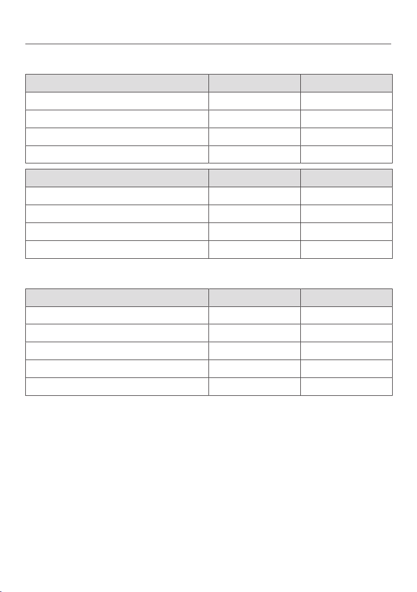
Burner ratings
*INSTALLATION*
Burner ratings HR1934-3DF
Natural gas NG Btu/hr kW
Simmer burner 12,500 3.7
Power burner, rear 13,600 4.0
Power burner, front 19,500 5.7
Total cooktop output 98,200 28.8
Liquid propane LP Btu/hr kW
Simmer burner 12,500 3.7
Power burner, rear 13,000 3.8
Power burner, front 19,500 5.7
Total cooktop output 97,000 28.4
Burner ratings HR1935-3DF
Natural gas NG Btu/hr kW
Simmer burner 12,500 3.7
Power burner, rear 13,600 4.0
Power burner, front 19,500 5.7
Grill 19,000 5.6
Total cooktop output 84,100 24.6
113

Burner ratings
*INSTALLATION*
Burner ratings HR1936-3DF
Natural gas NG Btu/hr kW
Simmer burner 12,500 3.7
Power burner, rear 13,600 4.0
Power burner, front 19,500 5.7
Griddle plate 13,000 3.8
Total cooktop output 78,100 22.9
Liquid propane LP Btu/hr kW
Simmer burner 12,500 3.7
Power burner, rear 13,000 3.8
Power burner, front 19,500 5.7
Griddle plate 13,000 3.8
Total cooktop output 77,500 22.7
114

Burner ratings
*INSTALLATION*
Burner ratings HR1954-3DF
Natural gas NG Btu/hr kW
Simmer burner 10,000 2.9
Power burner, rear 13,600 4.0
Power burner, front 19,500 5.7
Total cooktop output 125,200 36.7
Liquid propane LP Btu/hr kW
Simmer burner 10,000 2.9
Power burner, rear 13,000 3.8
Power burner, front 19,500 5.7
Total cooktop output 124,000 36.3
Burner ratings HR1955-3DF
Natural gas NG Btu/hr kW
Simmer burner 10,000 2.9
Power burner, rear 13,600 4.0
Power burner, front 19,500 5.7
Grill 19,000 5.6
Total cooktop output 111,100 32.6
115
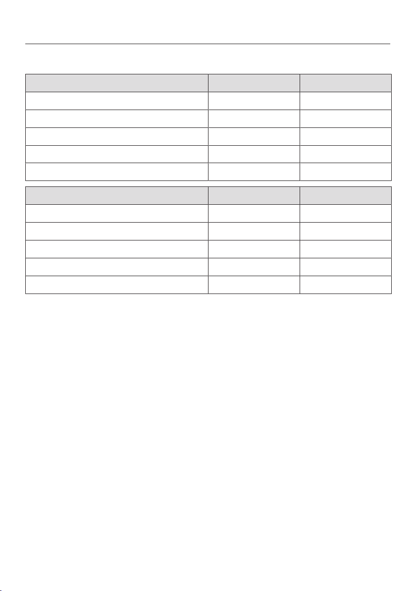
Burner ratings
*INSTALLATION*
Burner ratings HR1956-3DF
Natural gas NG Btu/hr kW
Simmer burner 10,000 2.9
Power burner, rear 13,600 4.0
Power burner, front 19,500 5.7
Griddle plate 13,000 3.8
Total cooktop output 105,100 30.8
Liquid propane LP Btu/hr kW
Simmer burner 10,000 2.9
Power burner, rear 13,000 3.8
Power burner, front 19,500 5.7
Griddle plate 13,000 3.8
Total cooktop output 104,500 30.6
116

Customer Service
117
Contact in the event of a fault
In the event of a fault which you cannot
remedy yourself, please contact your
Miele dealer or Miele Customer Service.
You can book a Miele Service Call
online at www.miele.com/service.
Contact information for Miele
Customer Service can be found at the
end of this document.
Please quote the model identifier and
serial number of your appliance (SN)
when contacting Miele Customer
Service. Both pieces of information can
be found on the data plate.
Data plate
The data plate is located behind the toe
kick panel. The toe kick panel is
attached to the toe kick of the Range by
magnets so it can be removed and put
back again easily.
There you can find the model number,
serial number and the connection data
(voltage/frequency/maximum rated
load) for your Range.
Have this information available if you
need to contact Miele so that any
issues can be rectified as quickly as
possible.
Appliance warranty and
product registration
You can register your product and/or
view the manufacturer´s warranty terms
and conditions for Miele appliances and
vacuum cleaners at
www.mieleusa.com.
Caring for the environment
118
Disposal of the packing
material
The cardboard box and packing
materials protect the appliance during
shipping. They have been designed to
be biodegradable and recyclable.
Ensure that any plastic wrappings,
bags, etc. are disposed of safely and
kept out of the reach of children.
Danger of suffocation!
Disposal of your old appliance
Electrical and electronic appliances
contain valuable materials. They also
contain certain substances, compounds
and components which were essential
for the proper functioning and safe use
of the equipment. Handling these
materials improperly by disposing of
them in your household waste can be
harmful to your health and the
environment. Therefore, please do not
dispose of your old appliance with
regular household waste and follow
local regulations on proper disposal.
Consult with local authorities, dealers or
Miele in order to dispose of and recycle
electrical and electronic appliances.
Miele assumes no responsibility for
deleting any personal data left on the
appliance being disposed. Please
ensure that your old appliance is kept
away from children until removal.
Observe safety requirements for
appliances that may tip over or pose an
entrapment hazard.

Copyrights and licenses
For the purpose of operating and controlling the communication module, Miele
uses proprietary or third-party software that is not covered by open source
licensing terms. This software/these software components are protected by
copyright. The copyrights held by Miele and third parties must be respected.
In addition, the integrated communication module contains software components
which are distributed under open source licensing terms. You can access these
open source components along with the associated copyright notices, copies of
the valid licensing terms, and any additional information locally via IP using a web
browser (http[s]://<ip address>/Licenses). The liability and warranty arrangements
for the open source licenses displayed in this location only apply in relation to the
respective rights holders.
119


Deutschland:
Miele & Cie. KG
Carl-Miele-Straße 29
33332 Gütersloh
Telefon: 0800 22 44 666
(kostenfrei)
Mo-Fr
Sa+So
8-20 Uhr
9-20 Uhr
Telefax: 05241 89-2090
Miele im Internet: www.miele.de
E-Mail: [email protected]
Luxemburg:
Österreich:
Miele Gesellschaft m.b.H.
Mielestraße 1
5071 Wals bei Salzburg
Telefon: 050 800 800
(Festnetz zum Ortstarif;
Mobilfunkgebühren abweichend)
Mo-Fr 8-17 Uhr
Telefax: 050 800 81219
Miele im Internet: www.miele.at
E-Mail: [email protected]
Miele S.à.r.l.
20, rue Christophe Plantin
Postfach 1011
L-1010 Luxemburg/Gasperich
Telefax: 00352 4 97 11-39
Miele im Internet: www.miele.lu
E-Mail: [email protected]
Telefon: 00352 4 97 11-30
Telefon: 00352 4 97 11-45
(Kundendienst)
Mo-Do
Fr
8.30-12.30, 13-17 Uhr
8.30-12.30, 13-16 Uhr
(Produktinformation)

M.-Nr. 11 918 390 / 02en-US, CA
HR1421-3 E, HR1622-3 i, HR1124-3 AG, HR1134-3 AG,
HR1135-3 AG, HR1136-3 AG, HR1724-3 DF, HR1924-3 DF,
HR1934-3 DF, HR1935-3 DF, HR1936-3 DF, HR1954-3 DF,
HR1955-3 DF, HR1956-3 DF